EP4080450B1 - System zur überwachung einer vorrichtung - Google Patents
System zur überwachung einer vorrichtung Download PDFInfo
- Publication number
- EP4080450B1 EP4080450B1 EP21169360.1A EP21169360A EP4080450B1 EP 4080450 B1 EP4080450 B1 EP 4080450B1 EP 21169360 A EP21169360 A EP 21169360A EP 4080450 B1 EP4080450 B1 EP 4080450B1
- Authority
- EP
- European Patent Office
- Prior art keywords
- infrared image
- temperature
- pixels
- hot spot
- infrared
- Prior art date
- Legal status (The legal status is an assumption and is not a legal conclusion. Google has not performed a legal analysis and makes no representation as to the accuracy of the status listed.)
- Active
Links
Images


Classifications
-
- G—PHYSICS
- G01—MEASURING; TESTING
- G01J—MEASUREMENT OF INTENSITY, VELOCITY, SPECTRAL CONTENT, POLARISATION, PHASE OR PULSE CHARACTERISTICS OF INFRARED, VISIBLE OR ULTRAVIOLET LIGHT; COLORIMETRY; RADIATION PYROMETRY
- G01J5/00—Radiation pyrometry, e.g. infrared or optical thermometry
-
- G—PHYSICS
- G06—COMPUTING OR CALCULATING; COUNTING
- G06T—IMAGE DATA PROCESSING OR GENERATION, IN GENERAL
- G06T7/00—Image analysis
- G06T7/0002—Inspection of images, e.g. flaw detection
- G06T7/0004—Industrial image inspection
-
- G—PHYSICS
- G01—MEASURING; TESTING
- G01J—MEASUREMENT OF INTENSITY, VELOCITY, SPECTRAL CONTENT, POLARISATION, PHASE OR PULSE CHARACTERISTICS OF INFRARED, VISIBLE OR ULTRAVIOLET LIGHT; COLORIMETRY; RADIATION PYROMETRY
- G01J5/00—Radiation pyrometry, e.g. infrared or optical thermometry
- G01J5/0066—Radiation pyrometry, e.g. infrared or optical thermometry for hot spots detection
-
- G—PHYSICS
- G01—MEASURING; TESTING
- G01J—MEASUREMENT OF INTENSITY, VELOCITY, SPECTRAL CONTENT, POLARISATION, PHASE OR PULSE CHARACTERISTICS OF INFRARED, VISIBLE OR ULTRAVIOLET LIGHT; COLORIMETRY; RADIATION PYROMETRY
- G01J5/00—Radiation pyrometry, e.g. infrared or optical thermometry
- G01J5/02—Constructional details
- G01J5/027—Constructional details making use of sensor-related data, e.g. for identification of sensor parts or optical elements
-
- G—PHYSICS
- G06—COMPUTING OR CALCULATING; COUNTING
- G06T—IMAGE DATA PROCESSING OR GENERATION, IN GENERAL
- G06T7/00—Image analysis
- G06T7/10—Segmentation; Edge detection
- G06T7/11—Region-based segmentation
-
- G—PHYSICS
- G06—COMPUTING OR CALCULATING; COUNTING
- G06T—IMAGE DATA PROCESSING OR GENERATION, IN GENERAL
- G06T7/00—Image analysis
- G06T7/10—Segmentation; Edge detection
- G06T7/136—Segmentation; Edge detection involving thresholding
-
- H—ELECTRICITY
- H04—ELECTRIC COMMUNICATION TECHNIQUE
- H04N—PICTORIAL COMMUNICATION, e.g. TELEVISION
- H04N23/00—Cameras or camera modules comprising electronic image sensors; Control thereof
- H04N23/20—Cameras or camera modules comprising electronic image sensors; Control thereof for generating image signals from infrared radiation only
-
- G—PHYSICS
- G01—MEASURING; TESTING
- G01J—MEASUREMENT OF INTENSITY, VELOCITY, SPECTRAL CONTENT, POLARISATION, PHASE OR PULSE CHARACTERISTICS OF INFRARED, VISIBLE OR ULTRAVIOLET LIGHT; COLORIMETRY; RADIATION PYROMETRY
- G01J5/00—Radiation pyrometry, e.g. infrared or optical thermometry
- G01J2005/0077—Imaging
-
- G—PHYSICS
- G06—COMPUTING OR CALCULATING; COUNTING
- G06T—IMAGE DATA PROCESSING OR GENERATION, IN GENERAL
- G06T2207/00—Indexing scheme for image analysis or image enhancement
- G06T2207/10—Image acquisition modality
- G06T2207/10048—Infrared image
-
- G—PHYSICS
- G06—COMPUTING OR CALCULATING; COUNTING
- G06T—IMAGE DATA PROCESSING OR GENERATION, IN GENERAL
- G06T2207/00—Indexing scheme for image analysis or image enhancement
- G06T2207/20—Special algorithmic details
- G06T2207/20084—Artificial neural networks [ANN]
-
- G—PHYSICS
- G06—COMPUTING OR CALCULATING; COUNTING
- G06T—IMAGE DATA PROCESSING OR GENERATION, IN GENERAL
- G06T2207/00—Indexing scheme for image analysis or image enhancement
- G06T2207/30—Subject of image; Context of image processing
- G06T2207/30108—Industrial image inspection
- G06T2207/30164—Workpiece; Machine component
Definitions
- the present invention relates to a system for monitoring a device such as a switchgear or motor and to a method for monitoring a device.
- EP3786598A1 relates to a system for monitoring a switchgear. It is described that the system comprises an infrared camera, a processing unit, and an output unit. It is described that the infrared camera is configured to acquire at least one infrared image of the switchgear. It is described that the processing unit is configured to determine a pixel in the at least one infrared image associated with a hottest temperature, and that the processing unit is configured to determine pixels in the at least one infrared image associated with a temperature that is within a threshold temperature of the hottest temperature. It is described that the processing unit is configured to determine that a hot spot exists in the switchgear, the determination comprising utilization of the determined pixels in the at least one infrared image. It is described that the output unit is configured to output an indication of a fault in the switchgear on the basis of the determined hot spot.
- Infrared (IR) images can be used to identify technical problems within electrical equipment (e.g. switchgear) that leads to overheating of components.
- electrical equipment e.g. switchgear
- IR Infrared
- a typical approach is to identify a region of interest for each phase. These regions can then be compared. If one is significantly hotter than the others, a fault has occurred.
- a modification of the switchgear during a service task in the field may influence the identification of phases in the IR image, and/or any movement or change in alignment of the camera's field of view leads to a change of the position of the regions and to incorrect operation.
- Appended claim 1 defines a system for monitoring a device.
- Appended claim 15 defines a method for monitoring a device.
- a system for monitoring a device comprising
- the infrared camera is configured to acquire a plurality of infrared images of the device, wherein the plurality of infrared images comprises a first infrared image and a second infrared image acquired a time period after the first infrared image.
- the processing unit is configured to determine a pixel in the first infrared image with a hottest temperature and determine a pixel in the second infrared image with a hottest temperature.
- the processing unit is configured to determine a first number of pixels in the first infrared image that have a temperature within a threshold temperature of the hottest temperature of the first infrared image and determine a second number of pixels in the second infrared image that have a temperature within the threshold temperature of the hottest temperature of the second infrared image.
- the processing unit is configured to determine a temperature magnitude comprising utilization of the hottest temperature in the second infrared image and/or a hottest temperature in a different infrared image of the plurality of infrared images acquired at a different time to the second infrared image.
- the processing unit is configured to determine a rate of change of temperature comprising utilization of the hottest temperature in the second infrared image and the hottest temperature in the different infrared image and a time duration between the acquisition of the second infrared image and the acquisition of the different infrared image.
- the processing unit is configured to determine that a hot spot exists in the device and/or a hot spot is developing in the device comprising utilization of a comparison between the first number of pixels and the second number of pixels and utilization of the temperature magnitude and the rate of change of temperature.
- the output unit is configured to output an indication of a fault in the device on the basis of the determination that a hot spot exists and/or is developing.
- the change in pixel numbers can be continually calculated with respect to two temporally adjacent infrared images and those images also used to determine a maximum temperature and rate of change of temperature and all of this information used to determine if there is a hot spot.
- an initial infrared image can be acquired and the number of pixels calculated and this can be compared to the number of pixels in a series of infrared images that are then acquired.
- temporally adjacent images can be used to determine both a maximum temperature and a rate of temperature which when used with the developing change in pixel number enables a hot spot to be identified as developing.
- the different infrared image is the first infrared image.
- the different infrared image is not the first infrared
- the different infrared image was acquired at a time between the first infrared image and the second infrared image, or the second infrared image was acquired at a time between the first infrared image and the different infrared image.
- the time period between acquisitions of the first infrared image and the second infrared image is greater than the time duration between acquisitions of the second infrared image and the different infrared image.
- the threshold temperature is a fixed temperature offset.
- the comparison between the first number of pixels and the second number of pixels comprises a determination of a pixel count difference equal to the second number of pixels subtracted from the first number of pixels.
- the threshold pixel count number is fixed.
- the threshold pixel could number is a function of the hottest temperature in the first infrared image and/or in the second infrared image.
- the determination that the hot spot exists in the device and/or the hot spot is developing in the device comprises an analysis of one or more of: a shape of at least one region within the determined pixels in the first infrared image and second infrared image; a size of the at least one region within the determined pixels in the first infrared image and second infrared image; a position of the at least one region within the determined pixels in the first infrared image and second infrared image.
- the determination that the hot spot exists in the device and/or the hot spot is developing in the device comprises a determination that a region in the second infrared image is smaller than a corresponding region in the first infrared image.
- the determination that the hot spot exists in the device and/or the hot spot is developing in the device comprises a determination that a number of regions in the second infrared image is smaller than a number of regions in the first infrared image.
- the determination that the hot spot exists in the device and/or the hot spot is developing in the device comprises utilization of a machine learning algorithm
- the plurality of infrared images were acquired at different times, wherein the processing unit is configured to determine a pixel in each of the plurality of infrared images associated with a hottest temperature in each of the plurality of infrared images, wherein the processing unit is configured to determine a number of threshold pixels in each of the plurality of infrared images associated with a temperature that is within the threshold temperature of the hottest temperature in each of the plurality of infrared images, and wherein the determination that the hot spot exists in the device and/or the hot spot is developing in the device comprises a determination of a rate of change of the number of threshold pixels with time.
- a method for monitoring a device comprising:
- Figs. 1-4 relates to a system for monitoring a device and a method for monitoring a device.
- the system for monitoring a device comprises an infrared camera, a processing unit, and an output unit.
- the infrared camera is configured to acquire a plurality of infrared images of the device.
- the plurality of infrared images comprises a first infrared image and a second infrared image acquired a time period after the first infrared image.
- the processing unit is configured to determine a pixel in the first infrared image with a hottest temperature and determine a pixel in the second infrared image with a hottest temperature.
- the processing unit is configured to determine a first number of pixels in the first infrared image that have a temperature within a threshold temperature of the hottest temperature of the first infrared image and determine a second number of pixels in the second infrared image that have a temperature within the threshold temperature of the hottest temperature of the second infrared image.
- the processing unit is configured to determine a temperature magnitude comprising utilization of the hottest temperature in the second infrared image and/or a hottest temperature in a different infrared image of the plurality of infrared images acquired at a different time to the second infrared image.
- the processing unit is configured to determine a rate of change of temperature comprising utilization of the hottest temperature in the second infrared image and the hottest temperature in the different infrared image and a time duration between the acquisition of the second infrared image and the acquisition of the different infrared image.
- the processing unit is configured to determine that a hot spot exists in the device and/or a hot spot is developing in the device comprising utilization of:
- the output unit is configured to output an indication of a fault in the device on the basis of the determination that a hot spot exists and/or is developing.
- the temperature magnitude is the hottest temperature in the second infrared image.
- the temperature magnitude is the hottest temperature in the different infrared image.
- the temperature magnitude is an average of the hottest temperature in the second infrared image and the hottest temperature in the different infrared image.
- the different infrared image is the first infrared image.
- the different infrared image was acquired at a time between the first infrared image and the second infrared image, or the second infrared image was acquired at a time between the first infrared image and the different infrared image.
- the time period between acquisitions of the first infrared image and the second infrared image is greater than the time duration between acquisitions of the second infrared image and the different infrared image.
- the threshold temperature is a fixed temperature offset.
- the comparison between the first number of pixels and the second number of pixels comprises a determination of a pixel count difference equal to the second number of pixels subtracted from the first number of pixels.
- the determination that the hot spot exists in the device and/or the hot spot is developing in the device comprises a comparison of the pixel count difference with a threshold pixel count number
- the threshold pixel count number is fixed.
- the threshold pixel could number is a function of the hottest temperature in the first infrared image and/or in the second infrared image.
- the determination that the hot spot exists in the device and/or the hot spot is developing in the device comprises an analysis of one or more of: a shape of at least one region within the determined pixels in the first infrared image and second infrared image; a size of the at least one region within the determined pixels in the first infrared image and second infrared image; a position of the at least one region within the determined pixels in the first infrared image and second infrared image.
- the determination that the hot spot exists in the device and/or the hot spot is developing in the device comprises a determination that a region in the second infrared image is smaller than a corresponding region in the first infrared image.
- the determination that the hot spot exists in the device and/or the hot spot is developing in the device comprises a determination that a number of regions in the second infrared image is smaller than a number of regions in the first infrared image.
- the determination that the hot spot exists in the device and/or the hot spot is developing in the device comprises a determination that the number of regions in the second image is one.
- the device comprises two or more components of the same type that are loaded with substantially the same current; wherein the determination that the hot spot exists in the device and/or the hot spot is developing in the device comprises one or more of: a shape of a first region within the determined pixels in the second infrared image is different to a shape of a second region within the determined pixels in second infrared image; a size of a first region within the determined pixels in the second infrared image is different to a size of a second region within the determined pixels in the second infrared image; a position of a region within the determined pixels in the second infrared image is not associated with a position of the two or more components; a number of regions within the determined pixels in the second infrared image is less than a number of the two or more components.
- the determination that the hot spot exists in the device and/or the hot spot is developing in the device comprises a determination that there is only one region within the determined pixels in the second infrared image.
- the determination that the hot spot exists in the device and/or the hot spot is developing in the device comprises a generation of at least one binary image, wherein the determined pixels in the first and second infrared images are given a different binary value to the remaining pixels in the at least one infrared image.
- the determination that the hot spot exists in the device and/or the hot spot is developing in the device comprises utilization of a machine learning algorithm
- the machine learning algorithm is a trained neural network.
- the plurality of infrared images were acquired at different times.
- the processing unit is configured to determine a pixel in each of the plurality of infrared images associated with a hottest temperature in each of the plurality of infrared images.
- the processing unit is configured to determine a number of threshold pixels in each of the plurality of infrared images associated with a temperature that is within the threshold temperature of the hottest temperature in each of the plurality of infrared images.
- the determination that the hot spot exists in the device and/or the hot spot is developing in the device comprises a determination of a rate of change of the number of threshold pixels with time.
- the determination that the hot spot exists in the device and/or the hot spot is developing in the device comprises a comparison of the rate of change of the number of threshold pixels with time against a baseline rate of change of the number of threshold pixels with time.
- the device comprises at least a part of a medium voltage switchgear or comprises a motor.
- the processing unit is configured to predict a temperature at a location of the device associated with the pixel in the second infrared image with the hottest temperature comprising utilization of the temperature magnitude and the rate of change of temperature and a correlation.
- the correlation is a correlation of a plurality of temperature magnitudes and a plurality of rate of change of temperatures with a plurality of hotspot temperatures.
- the determination that the hot spot exists in the device and/or the hot spot is developing in the device comprises utilization of the predicted temperature.
- the determination that the hot spot exists in the device and/or the hot spot is developing in the device comprises a determination that the predicted temperature exceeds a threshold temperature.
- the processing unit is configured to select the correlation from a plurality of correlations of different operational scenarios for the device.
- Each of the plurality of correlations is a correlation of a plurality of temperature magnitudes and a plurality of rate of change of temperatures at the sensor location with a plurality of hotspot temperatures at the location.
- each of the plurality of correlations is determined through experiments or through simulations.
- a method for monitoring a device comprises:
- the temperature magnitude is the hottest temperature in the second infrared image.
- the temperature magnitude is the hottest temperature in the different infrared image.
- the temperature magnitude is an average of the hottest temperature in the second infrared image and the hottest temperature in the different infrared image.
- the different infrared image is the first infrared image.
- the different infrared image is not the first image and the different infrared image was acquired at a time between the first infrared image and the second infrared image, or the second infrared image was acquired at a time between the first infrared image and the different infrared image.
- the time period between acquisitions of the first infrared image and the second infrared image is greater than the time duration between acquisitions of the second infrared image and the different infrared image.
- the threshold temperature is a fixed temperature offset.
- the comparison between the first number of pixels and the second number of pixels comprises a determination of a pixel count difference equal to the second number of pixels subtracted from the first number of pixels.
- the determination that the hot spot exists in the device and/or the hot spot is developing in the device comprises a comparison of the pixel count difference with a threshold pixel count number
- the threshold pixel count number is fixed.
- the threshold pixel could number is a function of the hottest temperature in the first infrared image and/or in the second infrared image.
- the determining that the hot spot exists in the device and/or the hot spot is developing in the device comprises an analysis of one or more of: a shape of at least one region within the determined pixels in the first infrared image and second infrared image; a size of the at least one region within the determined pixels in the first infrared image and second infrared image; a position of the at least one region within the determined pixels in the first infrared image and second infrared image.
- the determining that the hot spot exists in the device and/or the hot spot is developing in the device comprises a determination that a region in the second infrared image is smaller than a corresponding region in the first infrared image.
- the determining that the hot spot exists in the device and/or the hot spot is developing in the device comprises a determination that a number of regions in the second infrared image is smaller than a number of regions in the first infrared image.
- the determination that the hot spot exists in the device and/or the hot spot is developing in the device comprises a determination that the number of regions in the second image is one.
- the device comprises two or more components of the same type that are loaded with substantially the same current; wherein the determination that the hot spot exists in the device and/or the hot spot is developing in the device comprises one or more of: a shape of a first region within the determined pixels in the second infrared image is different to a shape of a second region within the determined pixels in second infrared image; a size of a first region within the determined pixels in the second infrared image is different to a size of a second region within the determined pixels in the second infrared image; a position of a region within the determined pixels in the second infrared image is not associated with a position of the two or more components; a number of regions within the determined pixels in the second infrared image is less than a number of the two or more components.
- the determining that the hot spot exists in the device and/or the hot spot is developing in the device comprises a determination that there is only one region within the determined pixels in the second infrared image.
- the determining that the hot spot exists in the device and/or the hot spot is developing in the device comprises a generation of at least one binary image, wherein the determined pixels in the first and second infrared images are given a different binary value to the remaining pixels in the at least one infrared image.
- the determining that the hot spot exists in the device and/or the hot spot is developing in the device comprises utilization of a machine learning algorithm
- the machine learning algorithm is a trained neural network.
- the plurality of infrared images were acquired at different times, and wherein the method comprises determining by the processing unit a pixel in each of the plurality of infrared images associated with a hottest temperature in each of the plurality of infrared images, and determining by the processing unit a number of threshold pixels in each of the plurality of infrared images associated with a temperature that is within the threshold temperature of the hottest temperature in each of the plurality of infrared images, and the determining that the hot spot exists in the device and/or the hot spot is developing in the device comprises determining a rate of change of the number of threshold pixels with time.
- the determining that the hot spot exists in the device and/or the hot spot is developing in the device comprises comparing the rate of change of the number of threshold pixels with time against a baseline rate of change of the number of threshold pixels with time.
- the device comprises at least a part of a medium voltage switchgear or comprises a motor.
- the method comprises predicting by the processing unit a temperature at a location of the device associated with the pixel in the second infrared image with the hottest temperature comprising utilizing the temperature magnitude and the rate of change of temperature and a correlation, where the correlation is a correlation of a plurality of temperature magnitudes and a plurality of rate of change of temperatures with a plurality of hotspot temperatures, and where the determining that the hot spot exists in the device and/or the hot spot is developing in the device comprises utilizing the predicted temperature.
- the determining that the hot spot exists in the device and/or the hot spot is developing in the device comprises a determination that the predicted temperature exceeds a threshold temperature.
- the method comprises selecting by the processing unit the correlation from a plurality of correlations of different operational scenarios for the device, where each of the plurality of correlations is a correlation of a plurality of temperature magnitudes and a plurality of rate of change of temperatures with a plurality of hotspot temperatures.
- each of the plurality of correlations is determined through experiments or through simulations.
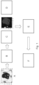
- Fig. 1 shows a detailed workflow relating to an example of the processing undertaken to determine a fault in a switchgear.
- A an IR image of a switchgear is acquired by an infrared camera.
- a pre-processing step can be used to increase the image quality. This can involve noise suppression, compensation of optical effects, removal of edges, etc.
- B the hottest temperature point within the image is acquired or identified, for example 35°C. There could be several pixels that have exactly the same highest temperature and either or both can be selected.
- all the pixels in the image that are within a threshold temperature range of the highest temperature are selected. For example, if the threshold temperature range is 7°C, then all pixels between 28°C and 35°C are selected.
- the threshold value is used to compute a range of values which are considered hot in this particular case.
- the threshold is the maximum temperature minus a specific value. This value can be a fixed number of degrees Celsius or a percentage of the current average temperature of the image, or a percentage of the maximum temperature of the image or a dynamically changing value in degrees Celsius depending on the average or maximum temperature of the image.
- the threshold can account for the influence of the ambient air temperature (inside the compartment and/or outside of the switchgear) as well as take into account any influence of compartment type. The result is shown in the following image.
- regions that are connected are identified.
- the pixel count, number of regions, shape, and/or size of individual regions is analysed to decide whether this is a fault or not.
- the pixel map is overlaid on a visual light image of the switchgear, for example of the switchgear compartment, to identify the position of the fault and/or to define which regions belong to which phase of a three-phase system.
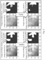
- the threshold is used to identify all camera pixels which are hotter than the threshold value. Images with a very strong hotspot will exhibit rather a small area. If there is no hotspot, the area is wide or broad, and in ideal cases even showing the different components of interest as distinct unconnected regions.
- the original IR image can be transformed to a new, binary image, consisting of only two colors (for example black and white), where one color (e.g. black) are the pixels above the threshold (the hot pixels) and other color (e.g. white) are the pixels below the threshold (the cold pixels) - this is just an example, where of the course the pixels can be the other way round, i.e. white is "hot” and black is "cold".
- this transformation can result in a mask for further processing of the IR image, for example by a machine learning algorithm such as a trained neural network.
- an algorithm applies a dynamic threshold to the image and returns only the pixels that are in the region of highest temperature. If the image shows a healthy device, this algorithm will separate the background (low temperature) from the foreground (high temperature). Thus it can be determined if a hot spot is developing because the number of pixels within a threshold of a maximum temperature starts to fall. Thus, a fault in an isolated device that is leading to a hot spot can be identified. Also, with respect to for example a three phase switchgear then parts of each phase typically exhibit equivalent current flow and due to Joule heating heat up to equivalent temperatures. Thus, the temperature difference between equivalent elements of the phases will be less than the threshold temperature range and thus all phases will be shown and the number of pixels stays relatively stable. It is then further established that there is a fault as the part with a fault remains at the highest temperature, but other parts of that phase and of the other phases start to disappear from within the temperature threshold range.
- the approach is to count the number of hot pixels, which is shown in Fig. 3 .
- cases with a strong fault will show a sharp decline in the number of hot pixels as the temperature increases in time.
- the number of pixels used for determining a hot spot situation can be derived for each scene by counting the pixels belonging to one component of interest. If the number of hot pixels drops below this value, the image is showing a hot spot.
- the number of pixels used for determining a hot spot situation can be also determined by experiments or simulations or via machine learning algorithms.
- the number of pixels of a hot region, compared to a baseline for a component can be used to indicate if there is a fault, and also the temporal change in the number of pixels within the threshold region can also be used, when compared against such a baseline, to indicate that the component is abnormally hot and that there is a fault.
- the image (for example a transformed binary image) can be further processed by machine learning.
- the machine learning model can be trained with typical patterns showing layout of hot pixels for images without hot spot, layout of hot pixels for images with a hot spot on a first specific component layout of hot pixels for images with a hot spot on a second component and so forth.
- the image can be fed to the model and the model will classify it as "no hot spot", "hot spot on the first component or the second component for example.
- the training data can be easily created for each new scene.
- a subject matter expert can recognize components on the IR or visual camera image and create typical patterns of black and white images that would be expected for healthy images, and images where different components have faults.
- the training data can be created from the office, without the need of expensive and time consuming experiments or simulations.
- the IR image discussed above can be composed of several individual images or sections of individual images, e.g. from different cameras in one panel or line-up or from different time steps.
- the inventors have however established that the maximum temperature and its rate of change of temperature provides further information that improves the accuracy of a fault determination based on the number of pixels within a threshold of the maximum temperature.
- Fig. 4 plots the two features T and dT/dt for the hottest pixel only.
- a temperature of 45°C is determined with a rate of change of temperature of 1.1 then it has been determined that under steady state conditions, with nothing else happening, the temperature will not develop into a critical temperature.
- a temperature of 65°C has been measure with a rate of change of temperature of 1.75, even though the temperature at the moment is not critical, it has been established that under steady state conditions with no change, the temperature at this location will develop into a critical temperature and remedial action should be taken before that critical temperature develops.
- the different lines are shown in Fig. 2 to enable the different correlations for different scenarios to be viewed more easily.
- a threshold between the healthy and the faulty region by considering a constant value of a pixel number within the threshold temperature. If the number of pixels is below that value, a fault can be determined to have occurred. On the other hand, if this line is a function of the maximum temperature in the image, a more flexible border appears and problems can be recognized at earlier stages.
- the exact position of the line can be determined by a Support Vector Machine (SVM) or similar algorithm. Alternatives to SVM are other machine learning classification or clustering algorithms.
- SVM Support Vector Machine
- a support vector machine or similar ML algorithm can be trained to specify whether a device is healthy or faulty by using the maximum temperature with the number of pixels within a threshold range of the maximum temperature and the temperature derivative as features.
Landscapes
- Engineering & Computer Science (AREA)
- Physics & Mathematics (AREA)
- General Physics & Mathematics (AREA)
- Spectroscopy & Molecular Physics (AREA)
- Multimedia (AREA)
- Signal Processing (AREA)
- Computer Vision & Pattern Recognition (AREA)
- Theoretical Computer Science (AREA)
- Quality & Reliability (AREA)
- Radiation Pyrometers (AREA)
- Image Analysis (AREA)
Claims (15)
- System zur Überwachung eines Geräts, umfassend:eine Infrarotkamera;eine Verarbeitungseinheit; undeine Ausgabeeinheit;wobei die Infrarotkamera eingerichtet ist, eine Vielzahl von Infrarotbildern des Geräts zu erfassen, wobei die Vielzahl von Infrarotbildern ein erstes Infrarotbild und ein zweites Infrarotbild umfasst, die in einem zeitlichen Abstand nach dem ersten Infrarotbild erfasst wurden;wobei die Verarbeitungseinheit eingerichtet ist, ein Pixel im ersten Infrarotbild mit der höchsten Temperatur zu bestimmen und ein Pixel im zweiten Infrarotbild mit der höchsten Temperatur zu bestimmen;wobei die Verarbeitungseinheit eingerichtet ist, eine erste Anzahl von Pixeln im ersten Infrarotbild zu bestimmen, die eine Temperatur innerhalb einer Schwellentemperatur der höchsten Temperatur des ersten Infrarotbilds aufweisen, und eine zweite Anzahl von Pixeln im zweiten Infrarotbild zu bestimmen, die eine Temperatur innerhalb der Schwellentemperatur der höchsten Temperatur des zweiten Infrarotbilds aufweisen;wobei die Verarbeitungseinheit eingerichtet ist, eine Temperaturgröße zu bestimmen, die die Nutzung der höchsten Temperatur im zweiten Infrarotbild und/oder einer höchsten Temperatur in einem anderen Infrarotbild der Vielzahl von Infrarotbildern, die zu einer anderen Zeit als dem zweiten Infrarotbild erfasst wurden, umfasst;wobei die Verarbeitungseinheit eingerichtet ist, eine Temperaturänderungsrate zu bestimmen, die die Nutzung der höchsten Temperatur im zweiten Infrarotbild und der höchsten Temperatur im anderen Infrarotbild sowie eine Zeitdauer zwischen der Erfassung des zweiten Infrarotbilds und der Erfassung des anderen Infrarotbilds umfasst;wobei die Verarbeitungseinheit eingerichtet ist, zu bestimmen, dass ein Hotspot im Gerät vorhanden ist und/oder sich ein Hotspot im Gerät entwickelt, wobei ein Vergleich zwischen der ersten Anzahl von Pixeln und der zweiten Anzahl von Pixeln sowie die Temperaturgröße und die Temperaturänderungsrate genutzt werden; undwobei die Ausgabeeinheit eingerichtet ist, eine Anzeige eines Fehlers im Gerät auf der Grundlage der Bestimmung, dass ein Hotspot vorhanden ist und/oder sich entwickelt, auszugeben.
- System nach Anspruch 1, wobei das andere Infrarotbild das erste Infrarotbild ist.
- System nach Anspruch 1, wobei das andere Infrarotbild zu einem Zeitpunkt erfasst wurde, der zwischen der Erfassung des ersten Infrarotbilds und des zweiten Infrarotbilds liegt, oder das zweite Infrarotbild zu einem Zeitpunkt erfasst wurde, der zwischen der Erfassung des ersten Infrarotbilds und des anderen Infrarotbilds liegt.
- System nach Anspruch 3, wobei der zeitliche Abstand zwischen der Erfassung des ersten Infrarotbilds und des zweiten Infrarotbilds größer ist als die Zeitdauer zwischen der Erfassung des zweiten Infrarotbilds und der Erfassung des anderen Infrarotbilds.
- System nach einem der Ansprüche 1 bis 4, wobei die Schwellentemperatur ein fester Temperaturversatz ist.
- System nach einem der Ansprüche 1 bis 5, wobei der Vergleich zwischen der ersten Anzahl von Pixeln und der zweiten Anzahl von Pixeln eine Bestimmung einer Pixelanzahl-Differenz umfasst, die gleich der zweiten Anzahl von Pixeln abzüglich der ersten Anzahl von Pixeln ist.
- System nach Anspruch 6, wobei die Bestimmung, dass der Hotspot im Gerät vorhanden ist und/oder sich entwickelt, einen Vergleich der Pixelanzahl-Differenz mit einer Schwellenpixelanzahlnummer umfasst.
- System nach Anspruch 7, wobei die Schwellenpixelanzahlnummer fest ist.
- System nach Anspruch 7, wobei die Schwellenpixelanzahlnummer eine Funktion der höchsten Temperatur im ersten Infrarotbild und/oder im zweiten Infrarotbild ist.
- System nach einem der Ansprüche 1 bis 9, wobei die Bestimmung, dass der Hotspot im Gerät vorhanden ist und/oder sich entwickelt, eine Analyse eines oder mehrerer der folgenden Merkmale umfasst:die Form mindestens eines Bereichs innerhalb der bestimmten Pixel im ersten und zweiten Infrarotbild;die Größe des mindestens einen Bereichs innerhalb der bestimmten Pixel im ersten und zweiten Infrarotbild;die Position des mindestens einen Bereichs innerhalb der bestimmten Pixel im ersten und zweiten Infrarotbild.
- System nach Anspruch 10, wobei die Bestimmung, dass der Hotspot im Gerät vorhanden ist und/oder sich entwickelt, eine Bestimmung umfasst, dass ein Bereich im zweiten Infrarotbild kleiner ist als ein entsprechender Bereich im ersten Infrarotbild.
- System nach einem der Ansprüche 10 bis 11, wobei die Bestimmung, dass der Hotspot im Gerät vorhanden ist und/oder sich entwickelt, eine Bestimmung umfasst, dass eine Anzahl von Bereichen im zweiten Infrarotbild kleiner ist als eine Anzahl von Bereichen im ersten Infrarotbild.
- System nach einem der Ansprüche 1 bis 12, wobei die Bestimmung, dass der Hotspot im Gerät vorhanden ist und/oder sich entwickelt, die Nutzung eines maschinellen Lernalgorithmus umfasst.
- System nach einem der Ansprüche 1 bis 13, wobei die Vielzahl von Infrarotbildern zu unterschiedlichen Zeiten erfasst wurde, wobei die Verarbeitungseinheit eingerichtet ist, dass sie für jedes der Infrarotbilder ein Pixel bestimmt, das mit der höchsten Temperatur in jedem der Infrarotbilder verbunden ist, wobei die Verarbeitungseinheit eingerichtet ist, dass sie eine Anzahl von Schwellenpixeln in jedem der Infrarotbilder bestimmt, die mit einer Temperatur verbunden sind, die innerhalb der Schwellentemperatur der höchsten Temperatur in jedem der Infrarotbilder liegt, und wobei die Bestimmung, dass der Hotspot im Gerät vorhanden ist und/oder sich entwickelt, eine Bestimmung der Temperaturänderungsrate der Anzahl der Schwellenpixel mit der Zeit umfasst.
- Ein Verfahren zur Überwachung eines Geräts, umfassend:
Erfassen durch eine Infrarotkamera eine Vielzahl von Infrarotbildern des Geräts, wobei die Vielzahl von Infrarotbildern ein erstes Infrarotbild und ein zweites Infrarotbild umfasst, die in einem zeitlichen Abstand nach dem ersten Infrarotbild erfasst wurden;Bestimmen durch eine Verarbeitungseinheit ein Pixel im ersten Infrarotbild mit der höchsten Temperatur und Bestimmen eines Pixels im zweiten Infrarotbild mit der höchsten Temperatur;Bestimmen durch die Verarbeitungseinheit eine erste Anzahl von Pixeln im ersten Infrarotbild, die eine Temperatur innerhalb einer Schwellentemperatur der höchsten Temperatur des ersten Infrarotbilds aufweisen, und Bestimmen einer zweiten Anzahl von Pixeln im zweiten Infrarotbild, die eine Temperatur innerhalb der Schwellentemperatur der höchsten Temperatur des zweiten Infrarotbilds aufweisen;Bestimmen durch die Verarbeitungseinheit eine Temperaturgröße, die die Nutzung der höchsten Temperatur im zweiten Infrarotbild und/oder einer höchsten Temperatur in einem anderen Infrarotbild der Vielzahl von Infrarotbildern, die zu einer anderen Zeit als dem zweiten Infrarotbild erfasst wurden, umfasst;Bestimmen durch die Verarbeitungseinheit eine Temperaturänderungsrate, die die Nutzung der höchsten Temperatur im zweiten Infrarotbild und der höchsten Temperatur im anderen Infrarotbild sowie eine Zeitdauer zwischen der Erfassung des zweiten Infrarotbilds und der Erfassung des anderen Infrarotbilds umfasst;Bestimmen durch die Verarbeitungseinheit, dass ein Hotspot im Gerät vorhanden ist und/oder sich ein Hotspot im Gerät entwickelt, wobei genutzt wird: ein Vergleich zwischen der ersten Anzahl von Pixeln und der zweiten Anzahl von Pixeln; und die Temperaturgröße und die Temperaturänderungsrate; und Ausgeben durch eine Ausgabeeinheit einer Anzeige eines Fehlers im Gerät auf der Grundlage der Bestimmung, dass ein Hotspot vorhanden ist und/oder sich entwickelt.
Priority Applications (3)
| Application Number | Priority Date | Filing Date | Title |
|---|---|---|---|
| EP21169360.1A EP4080450B1 (de) | 2021-04-20 | 2021-04-20 | System zur überwachung einer vorrichtung |
| US17/721,496 US12044576B2 (en) | 2021-04-20 | 2022-04-15 | System for monitoring a device |
| CN202210400002.4A CN115219039B (zh) | 2021-04-20 | 2022-04-15 | 用于监控设备的系统 |
Applications Claiming Priority (1)
| Application Number | Priority Date | Filing Date | Title |
|---|---|---|---|
| EP21169360.1A EP4080450B1 (de) | 2021-04-20 | 2021-04-20 | System zur überwachung einer vorrichtung |
Publications (3)
| Publication Number | Publication Date |
|---|---|
| EP4080450A1 EP4080450A1 (de) | 2022-10-26 |
| EP4080450B1 true EP4080450B1 (de) | 2025-06-04 |
| EP4080450C0 EP4080450C0 (de) | 2025-06-04 |
Family
ID=75625317
Family Applications (1)
| Application Number | Title | Priority Date | Filing Date |
|---|---|---|---|
| EP21169360.1A Active EP4080450B1 (de) | 2021-04-20 | 2021-04-20 | System zur überwachung einer vorrichtung |
Country Status (3)
| Country | Link |
|---|---|
| US (1) | US12044576B2 (de) |
| EP (1) | EP4080450B1 (de) |
| CN (1) | CN115219039B (de) |
Families Citing this family (3)
| Publication number | Priority date | Publication date | Assignee | Title |
|---|---|---|---|---|
| EP4266015B1 (de) * | 2022-04-21 | 2025-10-01 | Abb Schweiz Ag | System zur überwachung einer schaltanlage |
| CN116152195A (zh) * | 2023-02-20 | 2023-05-23 | 北京御航智能科技有限公司 | 光伏电池板的热斑检测方法、装置及电子设备 |
| CN119757463B (zh) * | 2024-12-13 | 2025-10-14 | 清华大学 | 基于锁相红外热成像的换流阀绝缘材料缺陷检测方法 |
Family Cites Families (40)
| Publication number | Priority date | Publication date | Assignee | Title |
|---|---|---|---|---|
| US5791400A (en) | 1996-07-01 | 1998-08-11 | Abb Air Preheater, Inc. | Linear scan hot spot detection system |
| WO2004044683A2 (en) * | 2002-11-06 | 2004-05-27 | Simmonds Precision Products, Inc. | Method for detection and recognition of fog presence within an aircraft compartment using video images |
| EP1828754B1 (de) * | 2004-11-12 | 2013-07-17 | Toyota Motor Engineering & Manufacturing North America, Inc. | Systeme und verfahren zur inspektion von beschichtungen, oberflächen und grenzflächen |
| CN201041515Y (zh) | 2006-12-29 | 2008-03-26 | 上海市东方海事工程技术有限公司 | 空气预热器红外热点探测系统 |
| CN201096525Y (zh) | 2007-09-30 | 2008-08-06 | 西安理工大学 | 电站锅炉空气预热器热点检测系统专用红外传感器装置 |
| KR101194906B1 (ko) * | 2012-08-09 | 2012-10-25 | 군산대학교산학협력단 | 신재생 에너지 발전 시스템에서 적외선 카메라를 이용한 고장 진단 장치 및 이를 위한 방법 |
| CN105191288B (zh) * | 2012-12-31 | 2018-10-16 | 菲力尔系统公司 | 异常像素检测 |
| JP6251056B2 (ja) * | 2014-01-23 | 2017-12-20 | 三菱重工機械システム株式会社 | ホットメルト検査装置及び方法 |
| CN204270461U (zh) | 2014-10-28 | 2015-04-15 | 王翠萍 | 一种红外热成像热点检测告警装置 |
| CN205070199U (zh) | 2015-10-15 | 2016-03-02 | 胜利油田恒源电气有限责任公司 | 中置式开关柜绝缘和温度探测装置 |
| CN205883160U (zh) | 2016-01-28 | 2017-01-11 | 天津理工大学 | 一种基于红外图像处理的光伏阵列热斑快速检测装置 |
| US9897493B2 (en) * | 2016-03-30 | 2018-02-20 | Air Products And Chemicals, Inc. | Method for temperature data acquisition |
| US10546207B2 (en) * | 2016-04-11 | 2020-01-28 | North Carolina Agricultural And Technical State University | Normalized defect characterization of pulse thermographic nondestructive evaluation |
| CN109196555B (zh) * | 2016-05-17 | 2021-12-31 | Abb瑞士股份有限公司 | 用于卷材制造监督的实时、完整卷材图像处理方法和系统 |
| US10054698B2 (en) * | 2016-08-31 | 2018-08-21 | General Electric Company | Temperature stabilization for detector heads |
| GB201620863D0 (en) * | 2016-12-08 | 2017-01-25 | Land Instr Int Ltd | Control system for furnace |
| CN110476416B (zh) * | 2017-01-26 | 2021-08-17 | 菲力尔系统公司 | 多个成像模式下红外成像的系统和方法 |
| CN206835046U (zh) | 2017-06-02 | 2018-01-02 | 西安热工研究院有限公司 | 一种自动检测光伏组件红外热斑的智能接线盒 |
| CN107917761A (zh) | 2017-11-17 | 2018-04-17 | 航天科工哈尔滨风华有限公司电站设备分公司 | 一种红外热点检测装置 |
| CN108590763B (zh) * | 2018-02-23 | 2023-04-14 | 中国矿业大学(北京) | 基于红外图像的矿井爆炸监测报警系统 |
| CA3099168A1 (en) * | 2018-05-03 | 2019-11-07 | Quantum IR Technologies, LLC | Infrared imaging systems and methods for oil leak detection |
| EP3803298B1 (de) * | 2018-05-25 | 2024-12-04 | Fluke Corporation | Optische gasbildgebungsysteme und -verfahren kompatibel mit ungekühlten wärmebildkameras |
| CN208707596U (zh) | 2018-08-03 | 2019-04-05 | 青海民族大学 | 一种热斑检测装置 |
| CL2018002477A1 (es) * | 2018-08-30 | 2018-10-19 | SL CAPITAL SpA | Sistema y método para la detección y digitalización del hormigón en estado fresco usando tecnología infraroja y funciones matemáticas de tendencia. |
| CN109215042B (zh) | 2018-09-28 | 2021-09-03 | 吉林电力股份有限公司科技开发分公司 | 一种基于计算机视觉的光伏电池板热斑效应检测系统及其计算方法 |
| CN208672148U (zh) | 2018-10-11 | 2019-03-29 | 青岛益堃达热能设备有限公司 | 一种基于热成像技术的电力电缆监测装置 |
| CN109829417A (zh) | 2019-01-28 | 2019-05-31 | 上海市建筑科学研究院 | 基于红外热成像技术监测机房热点的优化方法及监测装置 |
| CN209197907U (zh) | 2019-01-28 | 2019-08-02 | 上海市建筑科学研究院 | 一种红外热成像监测装置 |
| EP3716205B1 (de) | 2019-03-26 | 2022-02-23 | ABB Schweiz AG | Vorrichtung zum erfassen von hotspots |
| CN109993736B (zh) | 2019-03-29 | 2020-11-10 | 浙江大学 | 一种基于改进加权otsu算法的电气设备热成像分割查异方法 |
| EP3786598A1 (de) * | 2019-08-30 | 2021-03-03 | ABB Schweiz AG | System zur überwachung einer schaltanlage |
| CN210693862U (zh) | 2019-09-06 | 2020-06-05 | 华电电力科学研究院有限公司 | 一种光伏电站组件热斑故障自动检测装置 |
| CN110635768A (zh) | 2019-09-06 | 2019-12-31 | 华电电力科学研究院有限公司 | 一种光伏电站组件热斑故障自动检测装置及其工作方法 |
| WO2021050734A1 (en) * | 2019-09-11 | 2021-03-18 | Quantum IR Technologies, LLC | Rotary kiln thermal monitoring and cooling systems |
| CN110648489B (zh) * | 2019-09-11 | 2021-01-26 | 国网山东省电力公司 | 基于红外热成像燃点识别的库房预警系统 |
| CN210327503U (zh) | 2019-09-17 | 2020-04-14 | 无锡润俊精密机械有限公司 | 一种光伏组件热斑检测装置 |
| CN111179334B (zh) * | 2019-11-14 | 2024-03-19 | 青岛理工大学 | 基于多传感融合的海面小面积溢油区域检测系统及检测方法 |
| CN111080691A (zh) | 2019-12-17 | 2020-04-28 | 晶科电力科技股份有限公司 | 一种光伏组件红外热斑检测方法、装置 |
| CN111208169A (zh) * | 2020-02-20 | 2020-05-29 | 四川省特种设备检验研究院 | 一种适用于自然裂纹的脉冲涡流热成像缺陷检测方法 |
| CN111899256B (zh) * | 2020-08-12 | 2023-10-03 | 南京工程学院 | 一种基于红外图像热点特征聚类分析的退役锂电池筛选方法 |
-
2021
- 2021-04-20 EP EP21169360.1A patent/EP4080450B1/de active Active
-
2022
- 2022-04-15 US US17/721,496 patent/US12044576B2/en active Active
- 2022-04-15 CN CN202210400002.4A patent/CN115219039B/zh active Active
Also Published As
| Publication number | Publication date |
|---|---|
| US12044576B2 (en) | 2024-07-23 |
| EP4080450C0 (de) | 2025-06-04 |
| US20220333992A1 (en) | 2022-10-20 |
| EP4080450A1 (de) | 2022-10-26 |
| CN115219039B (zh) | 2025-05-02 |
| CN115219039A (zh) | 2022-10-21 |
Similar Documents
| Publication | Publication Date | Title |
|---|---|---|
| US12412261B2 (en) | System for monitoring a switchgear | |
| US12044576B2 (en) | System for monitoring a device | |
| dit Leksir et al. | Localization of thermal anomalies in electrical equipment using Infrared Thermography and support vector machine | |
| US12625003B2 (en) | System for monitoring a switchgear | |
| KR102147090B1 (ko) | 전력설비 내 발생하는 아크 및 핫스팟온도의 검출 및 위치표정 시스템 및 방법 | |
| US12092526B2 (en) | Apparatus for monitoring a switchgear | |
| CN115267609B (zh) | 故障检测系统 | |
| US12548139B2 (en) | System for monitoring a switchgear | |
| CN117613822B (zh) | 变频器快速停机方法、装置、设备及存储介质 | |
| KR102610309B1 (ko) | 인공지능 기반 열화상 감시 진단 시스템 | |
| CN117163790B (zh) | 一种故障报警方法、故障报警装置、电梯及可读存储介质 | |
| US12613139B2 (en) | System for monitoring a switchgear | |
| Gitzel et al. | Automatic Analysis of Thermograms–Challenge in Thermal Monitoring of Switchgears Using Infrared Cameras | |
| EP4414725A1 (de) | System zur überwachung einer schaltanlage | |
| EP4403937B1 (de) | System zur überwachung einer schaltanlage | |
| CN114264933B (zh) | 一种集成电路板的故障检测方法和故障检测系统 | |
| CN118483564A (zh) | 用于监测开关设备的系统 | |
| CN119168973A (zh) | 电缆相序识别方法、装置、计算机程序产品、存储介质 |
Legal Events
| Date | Code | Title | Description |
|---|---|---|---|
| PUAI | Public reference made under article 153(3) epc to a published international application that has entered the european phase |
Free format text: ORIGINAL CODE: 0009012 |
|
| STAA | Information on the status of an ep patent application or granted ep patent |
Free format text: STATUS: THE APPLICATION HAS BEEN PUBLISHED |
|
| AK | Designated contracting states |
Kind code of ref document: A1 Designated state(s): AL AT BE BG CH CY CZ DE DK EE ES FI FR GB GR HR HU IE IS IT LI LT LU LV MC MK MT NL NO PL PT RO RS SE SI SK SM TR |
|
| STAA | Information on the status of an ep patent application or granted ep patent |
Free format text: STATUS: REQUEST FOR EXAMINATION WAS MADE |
|
| 17P | Request for examination filed |
Effective date: 20230426 |
|
| RBV | Designated contracting states (corrected) |
Designated state(s): AL AT BE BG CH CY CZ DE DK EE ES FI FR GB GR HR HU IE IS IT LI LT LU LV MC MK MT NL NO PL PT RO RS SE SI SK SM TR |
|
| GRAP | Despatch of communication of intention to grant a patent |
Free format text: ORIGINAL CODE: EPIDOSNIGR1 |
|
| STAA | Information on the status of an ep patent application or granted ep patent |
Free format text: STATUS: GRANT OF PATENT IS INTENDED |
|
| INTG | Intention to grant announced |
Effective date: 20241119 |
|
| GRAJ | Information related to disapproval of communication of intention to grant by the applicant or resumption of examination proceedings by the epo deleted |
Free format text: ORIGINAL CODE: EPIDOSDIGR1 |
|
| STAA | Information on the status of an ep patent application or granted ep patent |
Free format text: STATUS: REQUEST FOR EXAMINATION WAS MADE |
|
| GRAP | Despatch of communication of intention to grant a patent |
Free format text: ORIGINAL CODE: EPIDOSNIGR1 |
|
| STAA | Information on the status of an ep patent application or granted ep patent |
Free format text: STATUS: GRANT OF PATENT IS INTENDED |
|
| INTC | Intention to grant announced (deleted) | ||
| GRAS | Grant fee paid |
Free format text: ORIGINAL CODE: EPIDOSNIGR3 |
|
| INTG | Intention to grant announced |
Effective date: 20250224 |
|
| GRAA | (expected) grant |
Free format text: ORIGINAL CODE: 0009210 |
|
| STAA | Information on the status of an ep patent application or granted ep patent |
Free format text: STATUS: THE PATENT HAS BEEN GRANTED |
|
| AK | Designated contracting states |
Kind code of ref document: B1 Designated state(s): AL AT BE BG CH CY CZ DE DK EE ES FI FR GB GR HR HU IE IS IT LI LT LU LV MC MK MT NL NO PL PT RO RS SE SI SK SM TR |
|
| REG | Reference to a national code |
Ref country code: GB Ref legal event code: FG4D |
|
| REG | Reference to a national code |
Ref country code: CH Ref legal event code: EP |
|
| REG | Reference to a national code |
Ref country code: DE Ref legal event code: R096 Ref document number: 602021031611 Country of ref document: DE |
|
| REG | Reference to a national code |
Ref country code: IE Ref legal event code: FG4D |
|
| U01 | Request for unitary effect filed |
Effective date: 20250623 |
|
| U07 | Unitary effect registered |
Designated state(s): AT BE BG DE DK EE FI FR IT LT LU LV MT NL PT RO SE SI Effective date: 20250701 |
|
| PG25 | Lapsed in a contracting state [announced via postgrant information from national office to epo] |
Ref country code: ES Free format text: LAPSE BECAUSE OF FAILURE TO SUBMIT A TRANSLATION OF THE DESCRIPTION OR TO PAY THE FEE WITHIN THE PRESCRIBED TIME-LIMIT Effective date: 20250604 |
|
| PG25 | Lapsed in a contracting state [announced via postgrant information from national office to epo] |
Ref country code: NO Free format text: LAPSE BECAUSE OF FAILURE TO SUBMIT A TRANSLATION OF THE DESCRIPTION OR TO PAY THE FEE WITHIN THE PRESCRIBED TIME-LIMIT Effective date: 20250904 Ref country code: GR Free format text: LAPSE BECAUSE OF FAILURE TO SUBMIT A TRANSLATION OF THE DESCRIPTION OR TO PAY THE FEE WITHIN THE PRESCRIBED TIME-LIMIT Effective date: 20250905 |
|
| PG25 | Lapsed in a contracting state [announced via postgrant information from national office to epo] |
Ref country code: PL Free format text: LAPSE BECAUSE OF FAILURE TO SUBMIT A TRANSLATION OF THE DESCRIPTION OR TO PAY THE FEE WITHIN THE PRESCRIBED TIME-LIMIT Effective date: 20250604 |
|
| PG25 | Lapsed in a contracting state [announced via postgrant information from national office to epo] |
Ref country code: HR Free format text: LAPSE BECAUSE OF FAILURE TO SUBMIT A TRANSLATION OF THE DESCRIPTION OR TO PAY THE FEE WITHIN THE PRESCRIBED TIME-LIMIT Effective date: 20250604 |
|
| PG25 | Lapsed in a contracting state [announced via postgrant information from national office to epo] |
Ref country code: RS Free format text: LAPSE BECAUSE OF FAILURE TO SUBMIT A TRANSLATION OF THE DESCRIPTION OR TO PAY THE FEE WITHIN THE PRESCRIBED TIME-LIMIT Effective date: 20250904 |
|
| PG25 | Lapsed in a contracting state [announced via postgrant information from national office to epo] |
Ref country code: IS Free format text: LAPSE BECAUSE OF FAILURE TO SUBMIT A TRANSLATION OF THE DESCRIPTION OR TO PAY THE FEE WITHIN THE PRESCRIBED TIME-LIMIT Effective date: 20251004 |
|
| PG25 | Lapsed in a contracting state [announced via postgrant information from national office to epo] |
Ref country code: SM Free format text: LAPSE BECAUSE OF FAILURE TO SUBMIT A TRANSLATION OF THE DESCRIPTION OR TO PAY THE FEE WITHIN THE PRESCRIBED TIME-LIMIT Effective date: 20250604 |
|
| PG25 | Lapsed in a contracting state [announced via postgrant information from national office to epo] |
Ref country code: CZ Free format text: LAPSE BECAUSE OF FAILURE TO SUBMIT A TRANSLATION OF THE DESCRIPTION OR TO PAY THE FEE WITHIN THE PRESCRIBED TIME-LIMIT Effective date: 20250604 |
|
| PG25 | Lapsed in a contracting state [announced via postgrant information from national office to epo] |
Ref country code: SK Free format text: LAPSE BECAUSE OF FAILURE TO SUBMIT A TRANSLATION OF THE DESCRIPTION OR TO PAY THE FEE WITHIN THE PRESCRIBED TIME-LIMIT Effective date: 20250604 |
|
| PLBE | No opposition filed within time limit |
Free format text: ORIGINAL CODE: 0009261 |
|
| STAA | Information on the status of an ep patent application or granted ep patent |
Free format text: STATUS: NO OPPOSITION FILED WITHIN TIME LIMIT |
|
| REG | Reference to a national code |
Ref country code: CH Ref legal event code: L10 Free format text: ST27 STATUS EVENT CODE: U-0-0-L10-L00 (AS PROVIDED BY THE NATIONAL OFFICE) Effective date: 20260416 |
|
| 26N | No opposition filed |
Effective date: 20260305 |