EP3716352A1 - Bloc batterie - Google Patents
Bloc batterie Download PDFInfo
- Publication number
- EP3716352A1 EP3716352A1 EP18880801.8A EP18880801A EP3716352A1 EP 3716352 A1 EP3716352 A1 EP 3716352A1 EP 18880801 A EP18880801 A EP 18880801A EP 3716352 A1 EP3716352 A1 EP 3716352A1
- Authority
- EP
- European Patent Office
- Prior art keywords
- liquid leakage
- battery pack
- sensor
- battery cell
- battery
- Prior art date
- Legal status (The legal status is an assumption and is not a legal conclusion. Google has not performed a legal analysis and makes no representation as to the accuracy of the status listed.)
- Granted
Links
Images



Classifications
-
- H—ELECTRICITY
- H01—ELECTRIC ELEMENTS
- H01M—PROCESSES OR MEANS, e.g. BATTERIES, FOR THE DIRECT CONVERSION OF CHEMICAL ENERGY INTO ELECTRICAL ENERGY
- H01M10/00—Secondary cells; Manufacture thereof
- H01M10/05—Accumulators with non-aqueous electrolyte
- H01M10/056—Accumulators with non-aqueous electrolyte characterised by the materials used as electrolytes, e.g. mixed inorganic/organic electrolytes
- H01M10/0564—Accumulators with non-aqueous electrolyte characterised by the materials used as electrolytes, e.g. mixed inorganic/organic electrolytes the electrolyte being constituted of organic materials only
- H01M10/0566—Liquid materials
- H01M10/0568—Liquid materials characterised by the solutes
-
- G—PHYSICS
- G01—MEASURING; TESTING
- G01M—TESTING STATIC OR DYNAMIC BALANCE OF MACHINES OR STRUCTURES; TESTING OF STRUCTURES OR APPARATUS, NOT OTHERWISE PROVIDED FOR
- G01M3/00—Investigating fluid-tightness of structures
- G01M3/02—Investigating fluid-tightness of structures by using fluid or vacuum
- G01M3/04—Investigating fluid-tightness of structures by using fluid or vacuum by detecting the presence of fluid at the leakage point
- G01M3/16—Investigating fluid-tightness of structures by using fluid or vacuum by detecting the presence of fluid at the leakage point using electric detection means
-
- G—PHYSICS
- G01—MEASURING; TESTING
- G01M—TESTING STATIC OR DYNAMIC BALANCE OF MACHINES OR STRUCTURES; TESTING OF STRUCTURES OR APPARATUS, NOT OTHERWISE PROVIDED FOR
- G01M3/00—Investigating fluid-tightness of structures
- G01M3/02—Investigating fluid-tightness of structures by using fluid or vacuum
- G01M3/04—Investigating fluid-tightness of structures by using fluid or vacuum by detecting the presence of fluid at the leakage point
- G01M3/16—Investigating fluid-tightness of structures by using fluid or vacuum by detecting the presence of fluid at the leakage point using electric detection means
- G01M3/18—Investigating fluid-tightness of structures by using fluid or vacuum by detecting the presence of fluid at the leakage point using electric detection means for pipes, cables or tubes; for pipe joints or seals; for valves; for welds; for containers, e.g. radiators
- G01M3/186—Investigating fluid-tightness of structures by using fluid or vacuum by detecting the presence of fluid at the leakage point using electric detection means for pipes, cables or tubes; for pipe joints or seals; for valves; for welds; for containers, e.g. radiators for containers, e.g. radiators
-
- H—ELECTRICITY
- H01—ELECTRIC ELEMENTS
- H01M—PROCESSES OR MEANS, e.g. BATTERIES, FOR THE DIRECT CONVERSION OF CHEMICAL ENERGY INTO ELECTRICAL ENERGY
- H01M10/00—Secondary cells; Manufacture thereof
- H01M10/05—Accumulators with non-aqueous electrolyte
- H01M10/052—Li-accumulators
- H01M10/0525—Rocking-chair batteries, i.e. batteries with lithium insertion or intercalation in both electrodes; Lithium-ion batteries
-
- H—ELECTRICITY
- H01—ELECTRIC ELEMENTS
- H01M—PROCESSES OR MEANS, e.g. BATTERIES, FOR THE DIRECT CONVERSION OF CHEMICAL ENERGY INTO ELECTRICAL ENERGY
- H01M10/00—Secondary cells; Manufacture thereof
- H01M10/05—Accumulators with non-aqueous electrolyte
- H01M10/056—Accumulators with non-aqueous electrolyte characterised by the materials used as electrolytes, e.g. mixed inorganic/organic electrolytes
- H01M10/0564—Accumulators with non-aqueous electrolyte characterised by the materials used as electrolytes, e.g. mixed inorganic/organic electrolytes the electrolyte being constituted of organic materials only
- H01M10/0566—Liquid materials
- H01M10/0569—Liquid materials characterised by the solvents
-
- H—ELECTRICITY
- H01—ELECTRIC ELEMENTS
- H01M—PROCESSES OR MEANS, e.g. BATTERIES, FOR THE DIRECT CONVERSION OF CHEMICAL ENERGY INTO ELECTRICAL ENERGY
- H01M10/00—Secondary cells; Manufacture thereof
- H01M10/42—Methods or arrangements for servicing or maintenance of secondary cells or secondary half-cells
- H01M10/4228—Leak testing of cells or batteries
-
- H—ELECTRICITY
- H01—ELECTRIC ELEMENTS
- H01M—PROCESSES OR MEANS, e.g. BATTERIES, FOR THE DIRECT CONVERSION OF CHEMICAL ENERGY INTO ELECTRICAL ENERGY
- H01M10/00—Secondary cells; Manufacture thereof
- H01M10/42—Methods or arrangements for servicing or maintenance of secondary cells or secondary half-cells
- H01M10/44—Methods for charging or discharging
-
- H—ELECTRICITY
- H01—ELECTRIC ELEMENTS
- H01M—PROCESSES OR MEANS, e.g. BATTERIES, FOR THE DIRECT CONVERSION OF CHEMICAL ENERGY INTO ELECTRICAL ENERGY
- H01M10/00—Secondary cells; Manufacture thereof
- H01M10/42—Methods or arrangements for servicing or maintenance of secondary cells or secondary half-cells
- H01M10/46—Accumulators structurally combined with charging apparatus
-
- H—ELECTRICITY
- H01—ELECTRIC ELEMENTS
- H01M—PROCESSES OR MEANS, e.g. BATTERIES, FOR THE DIRECT CONVERSION OF CHEMICAL ENERGY INTO ELECTRICAL ENERGY
- H01M10/00—Secondary cells; Manufacture thereof
- H01M10/42—Methods or arrangements for servicing or maintenance of secondary cells or secondary half-cells
- H01M10/48—Accumulators combined with arrangements for measuring, testing or indicating the condition of cells, e.g. the level or density of the electrolyte
-
- H—ELECTRICITY
- H01—ELECTRIC ELEMENTS
- H01M—PROCESSES OR MEANS, e.g. BATTERIES, FOR THE DIRECT CONVERSION OF CHEMICAL ENERGY INTO ELECTRICAL ENERGY
- H01M50/00—Constructional details or processes of manufacture of the non-active parts of electrochemical cells other than fuel cells, e.g. hybrid cells
- H01M50/20—Mountings; Secondary casings or frames; Racks, modules or packs; Suspension devices; Shock absorbers; Transport or carrying devices; Holders
- H01M50/204—Racks, modules or packs for multiple batteries or multiple cells
- H01M50/207—Racks, modules or packs for multiple batteries or multiple cells characterised by their shape
- H01M50/211—Racks, modules or packs for multiple batteries or multiple cells characterised by their shape adapted for pouch cells
-
- H—ELECTRICITY
- H01—ELECTRIC ELEMENTS
- H01M—PROCESSES OR MEANS, e.g. BATTERIES, FOR THE DIRECT CONVERSION OF CHEMICAL ENERGY INTO ELECTRICAL ENERGY
- H01M50/00—Constructional details or processes of manufacture of the non-active parts of electrochemical cells other than fuel cells, e.g. hybrid cells
- H01M50/50—Current conducting connections for cells or batteries
- H01M50/569—Constructional details of current conducting connections for detecting conditions inside cells or batteries, e.g. details of voltage sensing terminals
-
- H—ELECTRICITY
- H01—ELECTRIC ELEMENTS
- H01M—PROCESSES OR MEANS, e.g. BATTERIES, FOR THE DIRECT CONVERSION OF CHEMICAL ENERGY INTO ELECTRICAL ENERGY
- H01M2200/00—Safety devices for primary or secondary batteries
-
- H—ELECTRICITY
- H01—ELECTRIC ELEMENTS
- H01M—PROCESSES OR MEANS, e.g. BATTERIES, FOR THE DIRECT CONVERSION OF CHEMICAL ENERGY INTO ELECTRICAL ENERGY
- H01M2300/00—Electrolytes
- H01M2300/0017—Non-aqueous electrolytes
- H01M2300/0025—Organic electrolyte
-
- H—ELECTRICITY
- H02—GENERATION; CONVERSION OR DISTRIBUTION OF ELECTRIC POWER
- H02J—ELECTRIC POWER NETWORKS; CIRCUIT ARRANGEMENTS OR SYSTEMS FOR SUPPLYING OR DISTRIBUTING ELECTRIC POWER; SYSTEMS FOR STORING ELECTRIC ENERGY
- H02J7/00—Circuit arrangements for charging or discharging batteries or for supplying loads from batteries
- H02J7/90—Regulation of charging or discharging current or voltage
- H02J7/971—Regulation of charging or discharging current or voltage the charge cycle being controlled or terminated in response to non-electric parameters
-
- Y—GENERAL TAGGING OF NEW TECHNOLOGICAL DEVELOPMENTS; GENERAL TAGGING OF CROSS-SECTIONAL TECHNOLOGIES SPANNING OVER SEVERAL SECTIONS OF THE IPC; TECHNICAL SUBJECTS COVERED BY FORMER USPC CROSS-REFERENCE ART COLLECTIONS [XRACs] AND DIGESTS
- Y02—TECHNOLOGIES OR APPLICATIONS FOR MITIGATION OR ADAPTATION AGAINST CLIMATE CHANGE
- Y02E—REDUCTION OF GREENHOUSE GAS [GHG] EMISSIONS, RELATED TO ENERGY GENERATION, TRANSMISSION OR DISTRIBUTION
- Y02E60/00—Enabling technologies; Technologies with a potential or indirect contribution to GHG emissions mitigation
- Y02E60/10—Energy storage using batteries
Definitions
- the present invention relates to a battery pack.
- a non-aqueous electrolyte secondary battery there is a lithium ion secondary battery.
- the lithium ion secondary battery is lightweight, has a large capacity, and is widely used as, for example, a power source for a portable electronic apparatus.
- the non-aqueous electrolyte secondary battery is coupled to a control circuit, and thus configures a battery pack.
- the battery pack includes one or more battery cells formed of the non-aqueous electrolyte secondary battery, and the control circuit.
- the battery cell is coated with an outer package.
- a crack or the like may be generated in the outer package, and thus a non-aqueous electrolyte may leak out of the battery cell.
- the non-aqueous electrolyte leaks, charging and discharging of the battery cannot be effectively carried out.
- Patent Documents 1 and 2 disclose a liquid leakage sensor and a liquid leakage detection system which are used in a battery pack including a lead storage battery as a battery cell.
- Patent Document 3 discloses a battery pack that can detect liquid leakage of a lithium ion secondary battery.
- a battery forming the battery cell is the lead storage battery which uses an aqueous electrolyte which contains water as a solvent.
- the conductive aqueous electrolyte causes electrodes of the sensor to be short-circuited, and liquid leakage is detected by the system.
- an electrolyte of a non-aqueous system is not conductive. In a case where such an electrolyte leaks and comes into contact with electrodes, the sensor cannot detect a sufficient resistance value change (impedance change).
- a liquid leakage detector is directly coupled to a battery cell.
- a resistance value (impedance) between electrodes of a sensor changes due to liquid leakage cannot be differentiated from a case where the battery cell deteriorates due to overcharging or the like, and thus a resistance value (impedance) changes.
- droplets caused by condensation or the like are attached to the sensor, and thus an incorrect operation is performed according to misrecognition that liquid leakage has occurred.
- the present invention has been made in light of the problems above, and an object thereof is to provide a battery pack capable of detecting leakage of an electrolyte.
- the inventors found that, when a liquid leakage sensor is provided separately from a battery cell and a change between electrodes of the sensor which is caused by a leaked electrolyte is read, it is possible to increase liquid leakage detection sensitivity and to prevent misrecognition caused by other factors. In other words, in order to solve the problem, the following means is provided.
- the battery pack according to the aspect can detect leakage of an electrolyte.
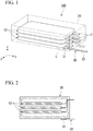
- FIG. 1 is a schematic perspective view illustrating a preferable example of a battery pack according to the present embodiment.
- a battery pack 100 according to the present embodiment includes battery cells 10, a casing 20, and a liquid leakage sensor 30.
- the casing 20 is illustrated by a dotted line for illustration of an internal structure.
- the battery cell 10 is configured with a non-aqueous electrolyte secondary battery.
- the non-aqueous electrolyte secondary battery is preferably a lithium ion secondary battery having a lithium ion as a carrier.
- the battery cell 10 includes a cathode, an anode, a separator, and an outer package.
- the cathode and the anode are disposed to oppose each other with the separator interposed therebetween.
- the outer package coats the cathode, the anode, and the separator except a cathode terminal 11 coupled to the cathode and an anode terminal 12 coupled to the anode.
- a shape of the battery cell 10 is a substantially rectangular shape, and is not limited to this example.
- the battery cells may be coupled in series to each other and may be coupled in parallel to each other as necessary.
- the cathode is preferably a plate-like (film-like) cathode collector provided with a cathode active material layer.
- the anode is preferably a plate-like (film-like) anode collector provided with an anode active material layer.
- the cathode active material layer and the anode active material layer are impregnated with an electrolyte. Ions are sent and received between the cathode and the anode via the electrolyte.
- an electrolyte of a non-aqueous type (hereinafter, referred to as a non-aqueous electrolyte) is used.
- a non-aqueous electrolyte an electrolyte is dissolved in a non-aqueous solvent.
- Non-aqueous solvent can be optionally selected, and an organic carbonate solvent is preferably used.
- the organic carbonate solvent at least one of a cyclic carbonate and a chain carbonate is preferably used. Only one of the cyclic carbonate and the chain carbonate may be used, and a mixture thereof may be used.
- cyclic carbonate a carbonate that can solvate an electrolyte may be used.
- an ethylene carbonate, a propylene carbonate, or a butylene carbonate may be preferably used.
- the carbonates may be used alone or may be used in combination of two or more.
- the chain carbonate can reduce viscosity of a cyclic carbonate.
- diethyl carbonate, dimethyl carbonate, or ethyl methyl carbonate may be preferably used.
- the carbonates may be used alone or may be used in combination of two or more.
- the organic carbonate solvent may be mixed with other components such as methyl acetate, ethyl acetate, methyl propionate, ethyl propionate, ⁇ -butyrolactone, 1,2-dimethoxyethane, and 1,2-diethoxyethane.
- Electrolyte to be contained in an electrolyte can be optionally selected.
- metal salts such as lithium salts and magnesium salts may be preferably used.
- the electrolyte is particularly preferably a metal salt including a fluorine atom, such as lithium hexafluorophosphate (LiPF 6 ) or lithium tetrafluoroborate (LiBF 4 ).
- the casing 20 stores the battery cells 10. In the example of the casing 20 illustrated in FIG. 1 , three stacked battery cells 10 are stored.
- the number of battery cells 10 stored in the casing 20 is not limited to this case, and the number may be one, two, or four or more.
- the casing 20 may have a rectangular shape, but may have other shapes as necessary.
- the battery cells 10 may be disposed to be stacked in contact with each other in the casing 20. Alternatively, the battery cells 10 may be stacked on each other with gaps and/or via other members.
- the casing 20 and the battery cells 10 may be in direct contact with each other, and may not be in direct contact with each other with another member interposed therebetween.
- a material forming the casing 20 may be selected as necessary and thus is not particularly limited, but preferably has insulation. It is possible to prevent a current from flowing via the casing 20.
- the number of leaked liquid retention region L may be one or more, and any number thereof may be selected.
- the leaked liquid retention region L is preferably disposed on surfaces (surface) of the casing 20 and/or the battery cell 10.
- the leaked liquid retention region L is a portion where a non-aqueous electrolyte can be easily retained when the non-aqueous electrolyte leaks out of the battery cell 10. In a case where there are two or more locations where a leaked liquid is easily retained, two or more leaked liquid retention regions L may be provided.
- a non-aqueous electrolyte is easily collected on a lower surface of the battery cell 1 0 and a bottom surface of the casing 20 due to the gravity.
- the periphery of the cathode terminal 11 and the anode terminal 12 of the battery cell 10 has weak contact with the outer package, and thus liquid leakage tends to occur thereon.
- such a portion may be considered as the leaked liquid retention region L.
- the leaked liquid retention region L may be provided at a plurality of positions selected as necessary.
- the leaked liquid retention region L may be disposed in a region overlapping at least one of the cathode terminal 11 and the anode terminal 12 in a plan view, and/or may be disposed between the cathode terminal 11 and the anode terminal 12 in a plan view.
- the region may be the entire bottom surface of the casing or may be a part of the bottom surface located inside the casing 20, and/or may be the entire bottom surface of the casing or may be a part of the bottom surface located outside the casing 20.
- the leaked liquid retention region L may be provided on a surface of the battery cell 10 which is disposed at closest to the casing in a plan view, for example, may be provided on a surface on the bottom surface side of the battery cell 1 0 disposed at the lowest position.
- the shortest distance from the short side of the bottom surface which is located on the cathode terminal 11 and the anode terminal 12 sides to each side of the leaked liquid retention region L is, for example, preferably 1/2 or less of a length of the long side, more preferably 1/3 or less, most preferably 1/4 or less, and particularly preferably 1/6 or less. Area of the leaked liquid retention region L may be optionally selected.
- a ratio of the area of the leaked liquid retention region L to areas (area) of the surfaces (surface) of the casing and/or the battery cell for example, an area of a surface on which the region L is disposed may be 1/50 or more, may be 1/30 or more, and may be 1/20 or more.
- the ratio may be 1/1 or less, may be 1/3 or less, may be 1/5 or less, and may be 1/10 or less.
- a shape of the leaked liquid retention region L in the present embodiment is a rectangular shape or a substantially rectangular shape having a long side and a short side.
- a shape of the leaked liquid retention region L is not limited to this example.
- a shape of the leaked liquid retention region L may be similar to the shape of the bottom surface of the casing, and the size of such a region L may be or may not be the same with that of the bottom surface of the casing.
- the leaked liquid retention region L may be disposed at a position where one of the long sides of the region L is closest to at least one of the short sides of the casing.
- At least a sensor unit 31 of the liquid leakage sensor 30 is disposed in the leaked liquid retention region L.
- the number of liquid leakage sensors 30 and the number of sensor units 31 included in the battery pack can be optionally selected. For example, the number may be one to ten, may be one to six, and may be one or two.
- the installation location and the number of liquid leakage sensors 30 can be optionally selected according to the device or the member.
- the number of sensor units 31 may be small, and, for example, one or about two to four sensor units 31 may be disposed at positions where a non-aqueous electrolyte is easily gathered.
- one or more sensor units 31 may be provided at other positions in addition to positions where a non-aqueous electrolyte is easily gathered due to the gravity.
- the liquid leakage sensor 30 detects liquid leakage from the battery cell 10.
- the liquid leakage sensor 30 preferably includes the sensor unit 31 and a wiring portion 32 extending from the sensor unit 31.
- the sensor unit 31 is provided in the leaked liquid retention region L.
- the sensor unit 31 illustrated in FIG. 1 is disposed on the bottom surface inside the casing 20 around the cathode terminal 11 and the anode terminal 12.
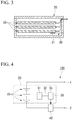
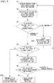
- An installation position of the sensor unit 31 is not limited to the position, and may be disposed on the bottom surface outside the casing 20 as illustrated in FIG. 2 , and may be disposed on the lower surface of the battery cell 10 as illustrated in FIG. 3 .
- Positions of the wiring portion 32 and a liquid leakage determination unit 33 coupled to the wiring portion 32 may be set to any selected locations inside or outside the casing.
- a single liquid leakage determination unit may be coupled to a plurality of sensor units.
- the liquid leakage sensor 30 is independent from the battery cell 10.
- the independence from the battery cell 10 indicates that the liquid leakage sensor 30 is independent from a circuit operating the battery cell 10.
- wirings extending from the cathode terminal 11 and the anode terminal 12 of the battery cell 10 are not directly coupled to the wiring portion 32 of the liquid leakage sensor 30.
- the liquid leakage sensor 30 may output detected measurement information without using a charging/discharging circuit of the battery cell 10.
- the charging/discharging circuit of the battery pack may be a circuit located over both of the inside and the outside of the casing which stores the battery cells.
- the liquid leakage sensor 30 is not coupled to a portion of the charging/discharging circuit which is included in the casing. Measurement information detected by the liquid leakage sensor 30 may be sent to an output destination located outside the casing via a wiring that does not influence charging and discharging of the battery cell 10.
- the output destination may be disposed at the other portion of the charging/discharging circuit located outside the casing.
- FIG. 4 is a diagram schematically illustrating a circuit structure of the battery pack 100 according to the present embodiment.
- the battery cells 10 arranged in series are coupled to a first terminal 1 and a second terminal 2.
- the first terminal 1 and the second terminal 2 are coupled to a main device or a charger.
- a charging control unit 40 is disposed between the first terminal 1 and the second terminal 2.
- the wiring portion 32 extending from the sensor unit 31 is coupled to the liquid leakage determination unit 33.
- information regarding the liquid leakage is sent to the charging control unit 40, and at least charging of the battery cells 10 is stopped.
- a wiring between the liquid leakage determination unit 33 and the charging control unit 40 is a wiring via which information is delivered between circuits.
- a circuit charging and discharging the battery cells 10 is differentiated from a circuit operating the liquid leakage sensor 30 by the wiring.
- the wiring is used to deliver information, and thus does not influence impedance of the battery cell 10.
- the circuits are separated from each other, and are thus differentiated from each other.
- the circuits are differentiated from each other, and thus it is possible to prevent the impedance of the liquid leakage sensor 30 from being influenced by deterioration or the like in the battery cell 10.
- FIG. 5 is a plan view illustrating the liquid leakage sensor 30 of the battery pack according to the present embodiment.
- the sensor unit 31 illustrated in FIG. 5 includes a first electrode 31A and a second electrode 31B.
- the first electrode 31A and the second electrode 31B are formed on an insulating substrate 31C.
- the first electrode 31A and the second electrode 31B are disposed to be separated from each other on the substrate 31C and are thus insulated from each other.
- FIG. 6 is a schematic diagram illustrating the enlarged periphery of the electrodes of the sensor unit 31.
- (a) of FIG. 6 is a picture before a non-aqueous electrolyte comes into contact with the electrodes
- (b) of FIG. 6 is a picture after the non-aqueous electrolyte comes into contact with the electrodes.
- whiskers grow from the electrodes after contact with the non-aqueous electrolyte.
- a cause of the metal deposition is not obvious, but the metal deposition may occur as a result of the first electrode 31A and the second electrode 31B being corroded by the non-aqueous electrolyte.
- impedance between the first electrode 31A and the second electrode 31B changes, and a voltage changes due to the impedance change in the present embodiment.
- FIG. 7 is a diagram schematically illustrating a temporal change of impedance between the first electrode 31A and the second electrode 31B, that is, a temporal change of a voltage.
- a first curve Z1 indicates a predetermined impedance change (that is, a voltage change) caused by attachment of a non-aqueous electrolyte
- a second curve Z2 indicates an impedance change caused by attachment of a solution with high conductivity
- a third curve Z3 indicates an impedance change caused by attachment of a solution with low conductivity.
- metal is deposited from the first electrode 31A and the second electrode 31B.
- the impedance gradually changes over time according to an amount of deposited metal. In other words, as indicated by the first curve Z1, the impedance gradually changes.
- the first electrode 31A and the second electrode 31B are short-circuited to each other.
- the impedance that is, a voltage rapidly decreases.
- a temporal change of the impedance between the first electrode 31A and the second electrode 31B that is, a temporal change of a voltage is slight.
- a tendency of an impedance change that is, a behavior of a voltage change differs depending on an object attached to the sensor unit 31.
- the liquid leakage determination unit 33 may determine that liquid leakage has occurred. A tendency of an impedance change is determined, and thus it is possible to avoid misrecognition of liquid leakage due to dew condensation or the like.
- the impedance between the first electrode 31A and the second electrode 31B may be obtained according to any method.
- the impedance may be obtained on the basis of a potential difference (voltage difference) between the first electrode 31A and the second electrode 31B, and may be obtained on the basis of an amount of a current flowing therebetween.
- the liquid leakage detection upper limit threshold value V LD_H and the liquid leakage detection lower limit threshold value V LD_L may be calculated on the basis of active energy of metal used for the first electrode 31A and the second electrode 31B, or the threshold values may be set through a test performed in advance.
- the first electrode 31A and the second electrode 31B preferably contain at least one metal selected from the group consisting of tin, silver, copper, nickel, zinc, and lead.
- the electrodes may be made of only one or two or more metals among the metals.
- the first electrode 31A and the second electrode 31B preferably contain tin. In a case where the first electrode 31A and the second electrode 31B are made of only tin, a speed of metal deposition is high, and the occurrence of liquid leakage can be determined faster. An amount of the metal contained in the electrodes can be optionally selected.
- the electrodes are preferably subjected to surface treatment, and the metal can be preferably used for the surface treatment.
- surfaces of the electrodes are preferably subjected to surface plating treatment with tin or a solder (an example of the solder is Sn-3.0% Ag-0.5% Cu) having tin as a main component.
- solder an example of the solder is Sn-3.0% Ag-0.5% Cu
- FIG. 8 is a flowchart illustrating an example of liquid leakage determination in the battery pack according to the present embodiment.
- the liquid leakage sensor 30 checks that the battery pack 100 performs a regular process (step S1).
- the sensor unit 31 measures a voltage value and/or impedance between the first electrode 31A and the second electrode 31B when the battery pack 100 performs a regular process, and the impedance may be obtained based on, for example, the voltage value.
- a voltage V D measured at this time is input to the liquid leakage determination unit 33 as a reference voltage (step S2).
- the sensor unit 31 measures a voltage and/or impedance between the first electrode 31A and the second electrode 31B for each predetermined measurement count.
- the liquid leakage determination unit 33 determines whether or not the measured voltage is less than the liquid leakage detection upper limit threshold value V LD_H (step S3). In a case where the measured voltage is equal to or more than the liquid leakage detection upper limit threshold value V LD_H , a regular state is maintained. In this case, measurement count is clear (step S30), and the flow is repeated.
- the liquid leakage determination unit 33 determines whether or not the measured voltage is equal to or more than the liquid leakage detection lower limit threshold value V LD_L (step S4). In a case where the measured voltage is less than the liquid leakage detection lower limit threshold value V LD_L , there is a high probability that short-circuit may occur as indicated by the second curve Z2 (refer to FIG. 7 ). In other words, abnormality is regarded to occur in the function of the liquid leakage sensor 30, and the flow is stopped (step S40).
- the sensor unit 31 measures a temporal change of impedance (that is, a voltage) (step S5).
- the liquid leakage determination unit 33 determines whether or not the voltage value is less than the liquid leakage detection upper limit threshold value V LD_H and is equal to or more than the liquid leakage detection upper limit threshold value V LD_H even though a detection time reaches a predetermined time or more (step S6).
- the condition is not satisfied, there is a probability that an impedance change occurs due to factors other than liquid leakage, and thus the flow returns to step S1.
- the liquid leakage determination unit 33 determines that liquid leakage occurs, information is sent to the charging control unit 40 from the liquid leakage determination unit 33, and at least charging of the battery cells 10 is stopped.
- FIG. 9 is a diagram schematically illustrating a circuit structure of another example of a battery pack 101 according to the present embodiment.
- the battery pack 101 illustrated in FIG. 9 further includes a second sensor 50.
- the second sensor 50 is disposed in parallel to the battery cells 10 with respect to the first terminal 1 and the second terminal 2.
- the second sensor 50 detects a voltage or current change of the battery cell 10.
- a state change of the battery cell 10 is detected by the second sensor 50 in addition to the liquid leakage sensor 30, and thus it is possible to further increase liquid leakage detection sensitivity.
- the battery pack 101 preferably has the second sensor 50 outside the casing 20.
- the battery pack 100 observes a phenomenon generated by a leaked electrolyte with the liquid leakage sensor 30, instead of a resistance value (DC impedance) change of the battery cell 10.
- the battery cell 10 and the liquid leakage sensor 30 are separated from each other in terms of circuit, and thus it is possible to prevent a resistance value (DC impedance) change of the battery cell 10 caused by deterioration or the like in the battery cell 10 from being misrecognized as an impedance change caused by liquid leakage.
- the liquid leakage sensor 30 determines whether or not a predetermined impedance change which is caused by attachment of a non-aqueous electrolyte to the sensor unit 31, that is, a voltage change is satisfied, and thus it is possible to differentiate an impedance change caused by short-circuit due to droplets generated by dew condensation from an impedance change caused by liquid leakage.
- a non-aqueous electrolyte contains a lithium salt including fluorine atoms
- the sensor unit 31 is made of tin
- a drop amount was 0.25 cc that is 3.5% of a total amount of the electrolyte of a single cell.
- the sensor unit of the electric leakage sensor was provided under the eight battery cells and around the cathode terminal and the anode terminal in the casing. The sensor unit was disposed on an inner surface of the casing.
- the electrodes of the sensor unit of the liquid leakage sensor were made of tin.
- a shape of the sensor unit was formed to be similar to the shape illustrated in FIG. 5 . After the battery pack was tilted once from a state in which a stacked surface was a lower surface to a state in which a side surface was a lower surface, a voltage applied between the electrodes of the liquid leakage sensor was measured.
- a drop amount was 0.50 cc.
- the remaining conditions were the same as in Example 1.
- FIG. 10 is a diagram illustrating that temporal changes of voltages applied between electrodes of the liquid leakage sensor in Example 1 and Example 2 were checked. As illustrated in FIG. 10 , a voltage between the electrodes gradually changed. In other words, a predetermined impedance change caused by attachment of the non-aqueous electrolyte to the sensor unit could be detected.
Landscapes
- Chemical & Material Sciences (AREA)
- Chemical Kinetics & Catalysis (AREA)
- Electrochemistry (AREA)
- General Chemical & Material Sciences (AREA)
- Engineering & Computer Science (AREA)
- Manufacturing & Machinery (AREA)
- Physics & Mathematics (AREA)
- General Physics & Mathematics (AREA)
- Condensed Matter Physics & Semiconductors (AREA)
- Inorganic Chemistry (AREA)
- Materials Engineering (AREA)
- Battery Mounting, Suspending (AREA)
- Secondary Cells (AREA)
Applications Claiming Priority (2)
| Application Number | Priority Date | Filing Date | Title |
|---|---|---|---|
| JP2017225044 | 2017-11-22 | ||
| PCT/JP2018/042798 WO2019102986A1 (fr) | 2017-11-22 | 2018-11-20 | Bloc batterie |
Publications (3)
| Publication Number | Publication Date |
|---|---|
| EP3716352A1 true EP3716352A1 (fr) | 2020-09-30 |
| EP3716352A4 EP3716352A4 (fr) | 2021-09-01 |
| EP3716352B1 EP3716352B1 (fr) | 2022-08-10 |
Family
ID=66631054
Family Applications (1)
| Application Number | Title | Priority Date | Filing Date |
|---|---|---|---|
| EP18880801.8A Active EP3716352B1 (fr) | 2017-11-22 | 2018-11-20 | Bloc batterie |
Country Status (5)
| Country | Link |
|---|---|
| US (1) | US11437654B2 (fr) |
| EP (1) | EP3716352B1 (fr) |
| JP (1) | JP7092148B2 (fr) |
| CN (1) | CN110495012A (fr) |
| WO (1) | WO2019102986A1 (fr) |
Cited By (1)
| Publication number | Priority date | Publication date | Assignee | Title |
|---|---|---|---|---|
| EP4443600A4 (fr) * | 2022-09-22 | 2025-08-20 | Lg Energy Solution Ltd | Unité de détection de fuite d'électrolyte et module de batterie la comprenant |
Families Citing this family (13)
| Publication number | Priority date | Publication date | Assignee | Title |
|---|---|---|---|---|
| KR102432481B1 (ko) * | 2018-01-19 | 2022-08-16 | 삼성전자 주식회사 | 전자 장치 및 전자 장치의 배터리 상태 감지 방법 |
| KR102464074B1 (ko) * | 2019-07-10 | 2022-11-04 | 후지쿠라 컴퍼지트 가부시키가이샤 | 액 검지 센서 |
| JP7276106B2 (ja) * | 2019-12-10 | 2023-05-18 | トヨタ自動車株式会社 | 蓄電装置 |
| KR102858853B1 (ko) * | 2020-03-11 | 2025-09-11 | 주식회사 엘지에너지솔루션 | 이차전지 및 이의 리튬 석출 검출 방법 |
| CN111463510B (zh) * | 2020-04-14 | 2021-05-11 | 傲普(上海)新能源有限公司 | 软包电池模组及其制造方法 |
| KR102893542B1 (ko) * | 2021-01-29 | 2025-11-28 | 주식회사 엘지에너지솔루션 | 배터리 팩, 배터리 장치 및 전해액 누설 검출 방법 |
| JP7540403B2 (ja) | 2021-06-29 | 2024-08-27 | 株式会社デンソー | 電池測定装置及び電池測定方法 |
| JP7775720B2 (ja) * | 2022-01-20 | 2025-11-26 | 株式会社デンソー | 二次電池システム |
| EP4303985A1 (fr) * | 2022-07-05 | 2024-01-10 | Saft Groupe | Appareil et procédé de détection de fuite d'électrolyte dans une cellule électrochimique |
| KR20240047176A (ko) * | 2022-10-04 | 2024-04-12 | 주식회사 엘지에너지솔루션 | 절연저항을 이용한 전해액 누액 감지부 및 이를 포함하는 전지모듈 |
| JP7694548B2 (ja) * | 2022-12-07 | 2025-06-18 | トヨタ自動車株式会社 | 漏液検知システム、及び積層セルモジュール |
| KR20250026028A (ko) * | 2023-08-16 | 2025-02-25 | 주식회사 엘지에너지솔루션 | 전해액 누액 감지가 가능한 전지셀 및 이를 포함하는 전지모듈 |
| CN118398996B (zh) * | 2024-04-19 | 2024-10-29 | 深圳市华宝储能科技有限公司 | 储能设备 |
Family Cites Families (20)
| Publication number | Priority date | Publication date | Assignee | Title |
|---|---|---|---|---|
| JPS6349761U (fr) | 1986-09-18 | 1988-04-04 | ||
| KR100196535B1 (ko) | 1996-07-16 | 1999-06-15 | 손욱 | 2차 전지 누액 감지 장치 |
| JP4608711B2 (ja) | 1999-09-10 | 2011-01-12 | ソニー株式会社 | バッテリパック |
| JP4517223B2 (ja) * | 2004-03-31 | 2010-08-04 | オリジン電気株式会社 | 帯状検出センサ−とそのセンサ−を備える液漏れ検出装置 |
| JP4899313B2 (ja) | 2004-12-22 | 2012-03-21 | トヨタ自動車株式会社 | 電池、電池の製造方法、及び電解液漏れ検査方法 |
| TWI309716B (en) * | 2006-06-14 | 2009-05-11 | Chin Ho Wang | Electrolyte detecting device and energy storing device using the same |
| JP2009032550A (ja) * | 2007-07-27 | 2009-02-12 | Sanyo Electric Co Ltd | 電源装置 |
| JP4921416B2 (ja) | 2008-05-23 | 2012-04-25 | Necフィールディング株式会社 | 電源装置、システム、及び処理方法 |
| JP4786700B2 (ja) | 2008-12-24 | 2011-10-05 | 三菱重工業株式会社 | 電池モジュール |
| JP2012226866A (ja) | 2011-04-15 | 2012-11-15 | Sumitomo Electric Ind Ltd | 溶融塩電池及びその液漏れ検知方法 |
| CN103208598B (zh) * | 2012-01-16 | 2016-06-29 | 微宏动力系统(湖州)有限公司 | 电池组及其漏液检测方法 |
| US8865333B2 (en) * | 2012-07-17 | 2014-10-21 | GM Global Technology Operations LLC | Systems and methods for mitigating battery damage caused by coolant leaks |
| CN103674454B (zh) * | 2012-09-24 | 2017-03-29 | 微宏动力系统(湖州)有限公司 | 电池组漏液检测系统 |
| US20140210603A1 (en) * | 2013-01-30 | 2014-07-31 | Ford Global Technologies, Llc | Fluid leakage detection system for vehicles |
| JP2014164857A (ja) * | 2013-02-22 | 2014-09-08 | Canon Inc | バッテリ |
| JP2016001525A (ja) | 2014-06-11 | 2016-01-07 | 株式会社Nttファシリティーズ | 液漏れ検出システム |
| JP2016134259A (ja) * | 2015-01-19 | 2016-07-25 | 住友重機械工業株式会社 | ハイブリッド型ショベル |
| JP2017174520A (ja) * | 2016-03-21 | 2017-09-28 | トヨタ自動車株式会社 | 密閉型二次電池 |
| JP6513054B2 (ja) | 2016-06-16 | 2019-05-15 | Kddi株式会社 | コンテンツ配信システムのクライアント装置、コンテンツの取得方法及びプログラム |
| US10886553B2 (en) | 2016-12-19 | 2021-01-05 | Vionx Energy Corporation | Large scale flow battery system |
-
2018
- 2018-11-20 CN CN201880024219.1A patent/CN110495012A/zh active Pending
- 2018-11-20 EP EP18880801.8A patent/EP3716352B1/fr active Active
- 2018-11-20 JP JP2019555306A patent/JP7092148B2/ja active Active
- 2018-11-20 US US16/604,193 patent/US11437654B2/en active Active
- 2018-11-20 WO PCT/JP2018/042798 patent/WO2019102986A1/fr not_active Ceased
Cited By (1)
| Publication number | Priority date | Publication date | Assignee | Title |
|---|---|---|---|---|
| EP4443600A4 (fr) * | 2022-09-22 | 2025-08-20 | Lg Energy Solution Ltd | Unité de détection de fuite d'électrolyte et module de batterie la comprenant |
Also Published As
| Publication number | Publication date |
|---|---|
| US11437654B2 (en) | 2022-09-06 |
| EP3716352A4 (fr) | 2021-09-01 |
| JP7092148B2 (ja) | 2022-06-28 |
| JPWO2019102986A1 (ja) | 2020-10-01 |
| CN110495012A (zh) | 2019-11-22 |
| US20200067145A1 (en) | 2020-02-27 |
| WO2019102986A1 (fr) | 2019-05-31 |
| EP3716352B1 (fr) | 2022-08-10 |
Similar Documents
| Publication | Publication Date | Title |
|---|---|---|
| US11437654B2 (en) | Battery pack | |
| EP3415938B1 (fr) | Procédé et dispositif de détection de défaillance à basse tension d'une batterie secondaire | |
| US12444751B2 (en) | Positive current collector, positive electrode plate, battery, and apparatus | |
| Chen et al. | Dead lithium: mass transport effects on voltage, capacity, and failure of lithium metal anodes | |
| US11372052B2 (en) | Jig pressing-type pressing short-circuiting inspection method | |
| Kim et al. | Investigation on internal short circuits of lithium polymer batteries with a ceramic-coated separator during nail penetration | |
| CN101772709B (zh) | 锂二次电池的寿命推测方法和劣化抑制方法、电池组、充电器 | |
| US9005786B2 (en) | Integrated cell voltage sense line fusing | |
| US12368190B2 (en) | Systems and methods of detecting Li dendrites | |
| KR101710655B1 (ko) | 기준전극을 구비하는 이차전지 | |
| US20150214582A1 (en) | Battery and method for determining the ageing state of a battery | |
| EP3014692B1 (fr) | Mécanisme de détection | |
| Seki et al. | Degradation mechanism analysis of all-solid-state lithium polymer secondary batteries by using the impedance measurement | |
| Chan et al. | Concentrated electrolytes for enhanced stability of Al-alloy negative electrodes in Li-ion batteries | |
| KR20130124326A (ko) | 내부 기준 전극을 지닌 리튬 기술을 기반으로 한 전기화학적 전지, 이의 제조 방법, 및 이의 애노드 및 캐소드의 전압 또는 임피던스를 동시에 모니터링하는 방법 | |
| KR101371994B1 (ko) | 전지 제어 장치 | |
| KR20160121179A (ko) | 기준 전극(reference electrode)을 포함하는 리튬 이온 이차 전지 | |
| US20210218118A1 (en) | Rechargeable battery with incorporated reference electrode | |
| CN105552464A (zh) | 全固体电池系统 | |
| KR101839405B1 (ko) | 메모리 칩의 파손 여부를 감지하는 검출 소자를 포함하는 보호회로 및 이를 포함하는 이차전지 팩 | |
| EP3327853A1 (fr) | Procede et circuit pour l'indication de la formation de dendrites dans un ensemble d'electrodes d'une batterie et batterie | |
| KR20190006452A (ko) | 리튬 이차전지의 회생 방법 | |
| KR20160091568A (ko) | 복수의 배터리 유닛들의 이상 상태를 판단하는 제어부를 포함하는 전지팩 | |
| JP2010086873A (ja) | 電池、電池の電極電位を推定するための方法および装置 | |
| US10705151B2 (en) | Intermediate structure unit for secondary cell and method for manufacturing secondary cell |
Legal Events
| Date | Code | Title | Description |
|---|---|---|---|
| STAA | Information on the status of an ep patent application or granted ep patent |
Free format text: STATUS: THE INTERNATIONAL PUBLICATION HAS BEEN MADE |
|
| PUAI | Public reference made under article 153(3) epc to a published international application that has entered the european phase |
Free format text: ORIGINAL CODE: 0009012 |
|
| STAA | Information on the status of an ep patent application or granted ep patent |
Free format text: STATUS: REQUEST FOR EXAMINATION WAS MADE |
|
| 17P | Request for examination filed |
Effective date: 20191011 |
|
| AK | Designated contracting states |
Kind code of ref document: A1 Designated state(s): AL AT BE BG CH CY CZ DE DK EE ES FI FR GB GR HR HU IE IS IT LI LT LU LV MC MK MT NL NO PL PT RO RS SE SI SK SM TR |
|
| AX | Request for extension of the european patent |
Extension state: BA ME |
|
| DAV | Request for validation of the european patent (deleted) | ||
| DAX | Request for extension of the european patent (deleted) | ||
| A4 | Supplementary search report drawn up and despatched |
Effective date: 20210729 |
|
| RIC1 | Information provided on ipc code assigned before grant |
Ipc: H01M 10/052 20100101AFI20210723BHEP Ipc: H01M 10/0568 20100101ALI20210723BHEP Ipc: H01M 10/0569 20100101ALI20210723BHEP Ipc: H01M 10/48 20060101ALI20210723BHEP Ipc: G01M 3/16 20060101ALI20210723BHEP Ipc: H01M 50/209 20210101ALI20210723BHEP Ipc: H01M 10/0525 20100101ALI20210723BHEP |
|
| REG | Reference to a national code |
Ref country code: DE Ref legal event code: R079 Ref document number: 602018039250 Country of ref document: DE Free format text: PREVIOUS MAIN CLASS: H01M0002100000 Ipc: H01M0010052000 |
|
| GRAP | Despatch of communication of intention to grant a patent |
Free format text: ORIGINAL CODE: EPIDOSNIGR1 |
|
| STAA | Information on the status of an ep patent application or granted ep patent |
Free format text: STATUS: GRANT OF PATENT IS INTENDED |
|
| RIC1 | Information provided on ipc code assigned before grant |
Ipc: H01M 50/569 20210101ALI20220225BHEP Ipc: H01M 50/211 20210101ALI20220225BHEP Ipc: G01M 3/18 20060101ALI20220225BHEP Ipc: H01M 10/0525 20100101ALI20220225BHEP Ipc: H01M 50/209 20210101ALI20220225BHEP Ipc: G01M 3/16 20060101ALI20220225BHEP Ipc: H01M 10/48 20060101ALI20220225BHEP Ipc: H01M 10/0569 20100101ALI20220225BHEP Ipc: H01M 10/0568 20100101ALI20220225BHEP Ipc: H01M 10/052 20100101AFI20220225BHEP |
|
| INTG | Intention to grant announced |
Effective date: 20220315 |
|
| RIN1 | Information on inventor provided before grant (corrected) |
Inventor name: KITAMURA, HIROKI Inventor name: TSURUOKA, MIKIO Inventor name: YAMASHIMA, MASAYUKI |
|
| GRAS | Grant fee paid |
Free format text: ORIGINAL CODE: EPIDOSNIGR3 |
|
| GRAA | (expected) grant |
Free format text: ORIGINAL CODE: 0009210 |
|
| STAA | Information on the status of an ep patent application or granted ep patent |
Free format text: STATUS: THE PATENT HAS BEEN GRANTED |
|
| AK | Designated contracting states |
Kind code of ref document: B1 Designated state(s): AL AT BE BG CH CY CZ DE DK EE ES FI FR GB GR HR HU IE IS IT LI LT LU LV MC MK MT NL NO PL PT RO RS SE SI SK SM TR |
|
| REG | Reference to a national code |
Ref country code: AT Ref legal event code: REF Ref document number: 1511217 Country of ref document: AT Kind code of ref document: T Effective date: 20220815 Ref country code: CH Ref legal event code: EP |
|
| REG | Reference to a national code |
Ref country code: DE Ref legal event code: R096 Ref document number: 602018039250 Country of ref document: DE |
|
| REG | Reference to a national code |
Ref country code: IE Ref legal event code: FG4D |
|
| REG | Reference to a national code |
Ref country code: NL Ref legal event code: MP Effective date: 20220810 |
|
| REG | Reference to a national code |
Ref country code: LT Ref legal event code: MG9D |
|
| PG25 | Lapsed in a contracting state [announced via postgrant information from national office to epo] |
Ref country code: SE Free format text: LAPSE BECAUSE OF FAILURE TO SUBMIT A TRANSLATION OF THE DESCRIPTION OR TO PAY THE FEE WITHIN THE PRESCRIBED TIME-LIMIT Effective date: 20220810 Ref country code: RS Free format text: LAPSE BECAUSE OF FAILURE TO SUBMIT A TRANSLATION OF THE DESCRIPTION OR TO PAY THE FEE WITHIN THE PRESCRIBED TIME-LIMIT Effective date: 20220810 Ref country code: PT Free format text: LAPSE BECAUSE OF FAILURE TO SUBMIT A TRANSLATION OF THE DESCRIPTION OR TO PAY THE FEE WITHIN THE PRESCRIBED TIME-LIMIT Effective date: 20221212 Ref country code: NO Free format text: LAPSE BECAUSE OF FAILURE TO SUBMIT A TRANSLATION OF THE DESCRIPTION OR TO PAY THE FEE WITHIN THE PRESCRIBED TIME-LIMIT Effective date: 20221110 Ref country code: NL Free format text: LAPSE BECAUSE OF FAILURE TO SUBMIT A TRANSLATION OF THE DESCRIPTION OR TO PAY THE FEE WITHIN THE PRESCRIBED TIME-LIMIT Effective date: 20220810 Ref country code: LV Free format text: LAPSE BECAUSE OF FAILURE TO SUBMIT A TRANSLATION OF THE DESCRIPTION OR TO PAY THE FEE WITHIN THE PRESCRIBED TIME-LIMIT Effective date: 20220810 Ref country code: LT Free format text: LAPSE BECAUSE OF FAILURE TO SUBMIT A TRANSLATION OF THE DESCRIPTION OR TO PAY THE FEE WITHIN THE PRESCRIBED TIME-LIMIT Effective date: 20220810 Ref country code: FI Free format text: LAPSE BECAUSE OF FAILURE TO SUBMIT A TRANSLATION OF THE DESCRIPTION OR TO PAY THE FEE WITHIN THE PRESCRIBED TIME-LIMIT Effective date: 20220810 |
|
| REG | Reference to a national code |
Ref country code: AT Ref legal event code: MK05 Ref document number: 1511217 Country of ref document: AT Kind code of ref document: T Effective date: 20220810 |
|
| PG25 | Lapsed in a contracting state [announced via postgrant information from national office to epo] |
Ref country code: PL Free format text: LAPSE BECAUSE OF FAILURE TO SUBMIT A TRANSLATION OF THE DESCRIPTION OR TO PAY THE FEE WITHIN THE PRESCRIBED TIME-LIMIT Effective date: 20220810 Ref country code: IS Free format text: LAPSE BECAUSE OF FAILURE TO SUBMIT A TRANSLATION OF THE DESCRIPTION OR TO PAY THE FEE WITHIN THE PRESCRIBED TIME-LIMIT Effective date: 20221210 Ref country code: HR Free format text: LAPSE BECAUSE OF FAILURE TO SUBMIT A TRANSLATION OF THE DESCRIPTION OR TO PAY THE FEE WITHIN THE PRESCRIBED TIME-LIMIT Effective date: 20220810 Ref country code: GR Free format text: LAPSE BECAUSE OF FAILURE TO SUBMIT A TRANSLATION OF THE DESCRIPTION OR TO PAY THE FEE WITHIN THE PRESCRIBED TIME-LIMIT Effective date: 20221111 |
|
| PG25 | Lapsed in a contracting state [announced via postgrant information from national office to epo] |
Ref country code: SM Free format text: LAPSE BECAUSE OF FAILURE TO SUBMIT A TRANSLATION OF THE DESCRIPTION OR TO PAY THE FEE WITHIN THE PRESCRIBED TIME-LIMIT Effective date: 20220810 Ref country code: RO Free format text: LAPSE BECAUSE OF FAILURE TO SUBMIT A TRANSLATION OF THE DESCRIPTION OR TO PAY THE FEE WITHIN THE PRESCRIBED TIME-LIMIT Effective date: 20220810 Ref country code: ES Free format text: LAPSE BECAUSE OF FAILURE TO SUBMIT A TRANSLATION OF THE DESCRIPTION OR TO PAY THE FEE WITHIN THE PRESCRIBED TIME-LIMIT Effective date: 20220810 Ref country code: DK Free format text: LAPSE BECAUSE OF FAILURE TO SUBMIT A TRANSLATION OF THE DESCRIPTION OR TO PAY THE FEE WITHIN THE PRESCRIBED TIME-LIMIT Effective date: 20220810 Ref country code: CZ Free format text: LAPSE BECAUSE OF FAILURE TO SUBMIT A TRANSLATION OF THE DESCRIPTION OR TO PAY THE FEE WITHIN THE PRESCRIBED TIME-LIMIT Effective date: 20220810 Ref country code: AT Free format text: LAPSE BECAUSE OF FAILURE TO SUBMIT A TRANSLATION OF THE DESCRIPTION OR TO PAY THE FEE WITHIN THE PRESCRIBED TIME-LIMIT Effective date: 20220810 |
|
| REG | Reference to a national code |
Ref country code: DE Ref legal event code: R097 Ref document number: 602018039250 Country of ref document: DE |
|
| PG25 | Lapsed in a contracting state [announced via postgrant information from national office to epo] |
Ref country code: SK Free format text: LAPSE BECAUSE OF FAILURE TO SUBMIT A TRANSLATION OF THE DESCRIPTION OR TO PAY THE FEE WITHIN THE PRESCRIBED TIME-LIMIT Effective date: 20220810 Ref country code: EE Free format text: LAPSE BECAUSE OF FAILURE TO SUBMIT A TRANSLATION OF THE DESCRIPTION OR TO PAY THE FEE WITHIN THE PRESCRIBED TIME-LIMIT Effective date: 20220810 |
|
| PLBE | No opposition filed within time limit |
Free format text: ORIGINAL CODE: 0009261 |
|
| STAA | Information on the status of an ep patent application or granted ep patent |
Free format text: STATUS: NO OPPOSITION FILED WITHIN TIME LIMIT |
|
| PG25 | Lapsed in a contracting state [announced via postgrant information from national office to epo] |
Ref country code: MC Free format text: LAPSE BECAUSE OF FAILURE TO SUBMIT A TRANSLATION OF THE DESCRIPTION OR TO PAY THE FEE WITHIN THE PRESCRIBED TIME-LIMIT Effective date: 20220810 Ref country code: AL Free format text: LAPSE BECAUSE OF FAILURE TO SUBMIT A TRANSLATION OF THE DESCRIPTION OR TO PAY THE FEE WITHIN THE PRESCRIBED TIME-LIMIT Effective date: 20220810 |
|
| REG | Reference to a national code |
Ref country code: CH Ref legal event code: PL |
|
| 26N | No opposition filed |
Effective date: 20230511 |
|
| REG | Reference to a national code |
Ref country code: BE Ref legal event code: MM Effective date: 20221130 |
|
| PG25 | Lapsed in a contracting state [announced via postgrant information from national office to epo] |
Ref country code: LI Free format text: LAPSE BECAUSE OF NON-PAYMENT OF DUE FEES Effective date: 20221130 Ref country code: CH Free format text: LAPSE BECAUSE OF NON-PAYMENT OF DUE FEES Effective date: 20221130 |
|
| PG25 | Lapsed in a contracting state [announced via postgrant information from national office to epo] |
Ref country code: SI Free format text: LAPSE BECAUSE OF FAILURE TO SUBMIT A TRANSLATION OF THE DESCRIPTION OR TO PAY THE FEE WITHIN THE PRESCRIBED TIME-LIMIT Effective date: 20220810 Ref country code: LU Free format text: LAPSE BECAUSE OF NON-PAYMENT OF DUE FEES Effective date: 20221120 |
|
| PG25 | Lapsed in a contracting state [announced via postgrant information from national office to epo] |
Ref country code: IE Free format text: LAPSE BECAUSE OF NON-PAYMENT OF DUE FEES Effective date: 20221120 |
|
| PG25 | Lapsed in a contracting state [announced via postgrant information from national office to epo] |
Ref country code: FR Free format text: LAPSE BECAUSE OF NON-PAYMENT OF DUE FEES Effective date: 20221130 Ref country code: BE Free format text: LAPSE BECAUSE OF NON-PAYMENT OF DUE FEES Effective date: 20221130 |
|
| PG25 | Lapsed in a contracting state [announced via postgrant information from national office to epo] |
Ref country code: CY Free format text: LAPSE BECAUSE OF FAILURE TO SUBMIT A TRANSLATION OF THE DESCRIPTION OR TO PAY THE FEE WITHIN THE PRESCRIBED TIME-LIMIT Effective date: 20220810 |
|
| PG25 | Lapsed in a contracting state [announced via postgrant information from national office to epo] |
Ref country code: MK Free format text: LAPSE BECAUSE OF FAILURE TO SUBMIT A TRANSLATION OF THE DESCRIPTION OR TO PAY THE FEE WITHIN THE PRESCRIBED TIME-LIMIT Effective date: 20220810 Ref country code: IT Free format text: LAPSE BECAUSE OF FAILURE TO SUBMIT A TRANSLATION OF THE DESCRIPTION OR TO PAY THE FEE WITHIN THE PRESCRIBED TIME-LIMIT Effective date: 20220810 Ref country code: HU Free format text: LAPSE BECAUSE OF FAILURE TO SUBMIT A TRANSLATION OF THE DESCRIPTION OR TO PAY THE FEE WITHIN THE PRESCRIBED TIME-LIMIT; INVALID AB INITIO Effective date: 20181120 |
|
| PG25 | Lapsed in a contracting state [announced via postgrant information from national office to epo] |
Ref country code: BG Free format text: LAPSE BECAUSE OF FAILURE TO SUBMIT A TRANSLATION OF THE DESCRIPTION OR TO PAY THE FEE WITHIN THE PRESCRIBED TIME-LIMIT Effective date: 20220810 |
|
| PG25 | Lapsed in a contracting state [announced via postgrant information from national office to epo] |
Ref country code: MT Free format text: LAPSE BECAUSE OF FAILURE TO SUBMIT A TRANSLATION OF THE DESCRIPTION OR TO PAY THE FEE WITHIN THE PRESCRIBED TIME-LIMIT Effective date: 20220810 |
|
| PG25 | Lapsed in a contracting state [announced via postgrant information from national office to epo] |
Ref country code: TR Free format text: LAPSE BECAUSE OF FAILURE TO SUBMIT A TRANSLATION OF THE DESCRIPTION OR TO PAY THE FEE WITHIN THE PRESCRIBED TIME-LIMIT Effective date: 20220810 |
|
| PGFP | Annual fee paid to national office [announced via postgrant information from national office to epo] |
Ref country code: DE Payment date: 20250930 Year of fee payment: 8 |
|
| PGFP | Annual fee paid to national office [announced via postgrant information from national office to epo] |
Ref country code: GB Payment date: 20251001 Year of fee payment: 8 |