EP3717094B1 - Tauchfilter für ein schwimmbad - Google Patents
Tauchfilter für ein schwimmbad Download PDFInfo
- Publication number
- EP3717094B1 EP3717094B1 EP18827207.4A EP18827207A EP3717094B1 EP 3717094 B1 EP3717094 B1 EP 3717094B1 EP 18827207 A EP18827207 A EP 18827207A EP 3717094 B1 EP3717094 B1 EP 3717094B1
- Authority
- EP
- European Patent Office
- Prior art keywords
- filtration
- water
- valve
- bowl
- submerged
- Prior art date
- Legal status (The legal status is an assumption and is not a legal conclusion. Google has not performed a legal analysis and makes no representation as to the accuracy of the status listed.)
- Active
Links
Images



Classifications
-
- B—PERFORMING OPERATIONS; TRANSPORTING
- B01—PHYSICAL OR CHEMICAL PROCESSES OR APPARATUS IN GENERAL
- B01D—SEPARATION
- B01D24/00—Filters comprising loose filtering material, i.e. filtering material without any binder between the individual particles or fibres thereof
- B01D24/02—Filters comprising loose filtering material, i.e. filtering material without any binder between the individual particles or fibres thereof with the filter bed stationary during the filtration
- B01D24/10—Filters comprising loose filtering material, i.e. filtering material without any binder between the individual particles or fibres thereof with the filter bed stationary during the filtration the filtering material being held in a closed container
- B01D24/14—Downward filtration, the container having distribution or collection headers or pervious conduits
-
- B—PERFORMING OPERATIONS; TRANSPORTING
- B01—PHYSICAL OR CHEMICAL PROCESSES OR APPARATUS IN GENERAL
- B01D—SEPARATION
- B01D24/00—Filters comprising loose filtering material, i.e. filtering material without any binder between the individual particles or fibres thereof
- B01D24/02—Filters comprising loose filtering material, i.e. filtering material without any binder between the individual particles or fibres thereof with the filter bed stationary during the filtration
- B01D24/10—Filters comprising loose filtering material, i.e. filtering material without any binder between the individual particles or fibres thereof with the filter bed stationary during the filtration the filtering material being held in a closed container
- B01D24/12—Downward filtration, the filtering material being supported by pervious surfaces
-
- B—PERFORMING OPERATIONS; TRANSPORTING
- B01—PHYSICAL OR CHEMICAL PROCESSES OR APPARATUS IN GENERAL
- B01D—SEPARATION
- B01D24/00—Filters comprising loose filtering material, i.e. filtering material without any binder between the individual particles or fibres thereof
- B01D24/46—Regenerating the filtering material in the filter
- B01D24/4631—Counter-current flushing, e.g. by air
- B01D24/4642—Counter-current flushing, e.g. by air with valves, e.g. rotating valves
-
- E—FIXED CONSTRUCTIONS
- E04—BUILDING
- E04H—BUILDINGS OR LIKE STRUCTURES FOR PARTICULAR PURPOSES; SWIMMING OR SPLASH BATHS OR POOLS; MASTS; FENCING; TENTS OR CANOPIES, IN GENERAL
- E04H4/00—Swimming or splash baths or pools
- E04H4/12—Devices or arrangements for circulating water, i.e. devices for removal of polluted water, cleaning baths or for water treatment
- E04H4/1209—Treatment of water for swimming pools
- E04H4/1263—Floating skimmers
-
- E—FIXED CONSTRUCTIONS
- E04—BUILDING
- E04H—BUILDINGS OR LIKE STRUCTURES FOR PARTICULAR PURPOSES; SWIMMING OR SPLASH BATHS OR POOLS; MASTS; FENCING; TENTS OR CANOPIES, IN GENERAL
- E04H4/00—Swimming or splash baths or pools
- E04H4/14—Parts, details or accessories not otherwise provided for
- E04H4/16—Parts, details or accessories not otherwise provided for specially adapted for cleaning
Definitions
- the present invention relates to the field of filtration systems for swimming pools and basins. It relates in particular to an immersed filtration device compatible with backwashing.
- non-submerged filtration devices for swimming pools and ponds.
- the filtration unit described in the document US20160002941 has a plurality of sand filter modules and a function of cleaning the filters by flowing water against the current.
- swimming pool water filtration systems comprising an immersed filtration device appear to be more advantageous because they offer greater compactness and limit the extent of the water pipes.
- an immersed device conventionally comprises a filter, for example made of fabric, immersed in the water of the basin, and a pump which circulates the water, by suction, in the filter, and its discharge into the basin after filtration. When the filter is clogged, it is taken out of the basin and cleaned, for example under a jet of water.
- cleaning means are known for non-submerged filtration devices (filter stainless steel, sand), consisting in circulating a counter current of water, so as to expel from the filter the particles that would be trapped there.
- non-submerged filtration devices filter stainless steel, sand
- these techniques are not directly applicable to submerged filtration devices, as this would lead to the particles extracted from the filter being rejected in the pond water.
- the present invention aims to overcome all or part of the aforementioned drawbacks.
- the invention relates to an immersed device for filtering the water in a basin, compatible with cleaning by circulating water against the current (backwashing).
- the invention also relates to a filtration system comprising said submerged device.
- the present invention relates to an immersed device for filtering the water of a basin, comprising a filtration bowl having a first end for collecting the water to be filtered from the basin and a second end intended to be connected to a first outlet duct. filtered water.
- the invention relates to a device 100 immersed in the water of a basin (or of a swimming pool) 200, used for the filtration of the water of said basin 200.
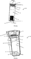
- the filtration device 100 comprises a filtration bowl 10, preferably of cylindrical shape ( figures 1a, 1b ).
- the submerged filtration device 100 is configured to directly collect the water to be filtered EAF of the basin 200, at a first end 11 of the filtration bowl 10; said first end 11 opens in practice into a box 90 filled with water from the basin via a mouth 21, without intermediate pipe ( figure 1b ).
- the absence of conduits or pipes between the inlet (first end 11) of the filtration device 100 and the pool water prevents pressure drops in the filtration system.
- the submerged device 100 is connected, at a second end 12 of the filtration bowl 10, to an outlet pipe 22 (called the first outlet pipe 22) of the filtered water EF.
- the first outlet pipe 22 is in fluid communication with a second delivery pipe 60 connected to a delivery nozzle 70, immersed in the water of the basin 200, intended to return the filtered water EF to the tank. basin 200.
- the filter bowl 10 comprises, inside its advantageously cylindrical walls and between its first end 11 and its second end 12, a filter 1 such as for example a sand filter; of course, the filter 1 could alternatively consist of a diatomaceous earth filter, a fiber filter, a cellular plastic pellet filter or any other type of filter.
- a filter 1 such as for example a sand filter; of course, the filter 1 could alternatively consist of a diatomaceous earth filter, a fiber filter, a cellular plastic pellet filter or any other type of filter.
- the filtration bowl 10 comprises a sieve basket 13 near its first end 11, a column of sand 1 (or any other solid or fibrous material capable of filtering) and a floor filter 14 integral with its second end 12.
- the sieve basket 13 on the one hand, and the floor filter 14 on the other hand, make it possible to maintain the column of sand in the filtration bowl 10, preventing the grains of sand from being driven by the circulation of water.
- the sieve basket 13 ( figure 4a ) has a cylindrical shape and acts as a sieve, preventing the sand from accessing an area above the sieve basket 13, towards the first end 11 of the filter bowl 10.
- the size of the sieve of this basket 13 is for example 550 microns.
- the filtration bowl 10 comprises a column of sand 1 (or any other solid or fibrous material capable of filtering) and a floor filter 14 integral with its second end 12, without a sieve basket 13 near its first end 11.
- the sieve basket 13 which prevents the grains of sand from being carried away by the circulation of water during the backwashing of the filtration device 100, in the first setting mode. above, is not essential if the water pressure used during the backwashing is suitable so as not to disperse and lift the column of sand from the filtration bowl 10 (this point will be discussed later).
- the floor filter 14 has a cylindrical shape and acts as a sieve, preventing the sand from accessing an area below the floor filter. 14, towards the second end 12 of the filtration bowl 10. It is made of stainless steel or plastic wires ( figure 4b ), as could also be the sieve basket 13.
- the son have a thickness of 4 mm, a triangular profile and are spaced from each other by less than 500 microns.
- the opening 14a of the floor filter 14 communicates with the first outlet duct 22 of the filtered water EF; a flange 14b of the floor filter 14, disposed around the opening 14a, is sealingly attached to the second end 12 of the filter bowl 10.
- the submerged filtration device 100 further comprises a valve module 30, integral with the first end 11 of the filtration bowl 10.
- the valve module 30 is located above the sieve basket 13.
- the valve module 30 is configured to allow the circulation of water from the first end 11 of the filtration bowl 10 (inlet of the water to be filtered EAF) to its second end 12 (outlet of the filtered water EF), that is to say a circulation of water according to a filtration stream.
- the circulation of the water against the current makes it possible to clean the filtration bowl 10 by backwashing, by expelling the particles which clog the floor filter 14 and the sand, towards the sieve basket 13 (when it is present) and / or to the valve module 30.
- the screen of the sieve basket 13 being wider than that of the floor filter 14, it allows said particles to pass.
- the sieve basket 13 can nevertheless block certain particles or filaments and gradually become clogged: this is why a filtration bowl 10 without a sieve basket 13 can sometimes be advantageous (second embodiment previously mentioned).
- valve 32 is movable along an axis 33 parallel to the axis of the filtration bowl 10 and releases or closes the valve opening 31 according to the flow of water circulation ( figures 2 and 3 ).
- the valve opening 31 may have a diameter between 50% and 90% of the diameter of the section of the filtration bowl 10.
- valve 32 of the valve module 30 closes the opening 31 due to the presence of a spring 34.
- said spring is arranged on the axis 33, bearing against the underside of the valve 32, and makes it possible to maintain the closed position of the valve 32 (opening 31 closed) when the water is not circulating according to the filtration current (c that is to say in situations of no circulation or circulation against the current).
- Seals 35 are advantageously provided at the level of the connection between the valve 32 and the shaft 33 and at the level of the connection between the valve 32 and the periphery of the opening 31, to seal the valve module 30, in closed position.
- the filtration device 100 also comprises a drain pipe 40, in communication with the filtration bowl 10. Its role is to evacuate to the sewers, the water laden with particles (backwash water) which passes through the sieve basket. 13 (when present) and / or which arrives near the valve module 30, against the current.
- a drain pipe 40 in communication with the filtration bowl 10. Its role is to evacuate to the sewers, the water laden with particles (backwash water) which passes through the sieve basket. 13 (when present) and / or which arrives near the valve module 30, against the current.
- the drain pipe 40 is located near the valve module 30, between the latter and the sieve basket 13 (when it is present).
- valve opening 31 of the valve module 30 is advantageously offset from at the first end 11 towards the inside of the filtration bowl 10, along the axis of revolution of said bowl 10.
- drain pipe 40 is preferably in communication with the bowl 10 in a zone located between the first end 11 and the '' valve opening 31 ( figure 2 ).
- the drain pipe 40 preferably comprises a defusing valve 41 ( figures 5 (a) and 5 (b) ).
- a defusing valve 41 figures 5 (a) and 5 (b) .
- the washing water pressure in the drain pipe 40 pushes the defusing valve 41 which comes through its seal to close an orifice 42: the washing water then continues. its way in the drain 40, in the direction of the sewers.
- the deactivation valve 41 opens, allowing air to pass through and thus deactivating the siphon (drain pipe 40): this prevents the water from continuing to drain. 'drain through the drain pipe 40 after stopping the counter-current circulation.
- the drain pipe 40 may be directly connected to an overflow pipe, the latter having a first end held in a sleeve for adjusting the water level in the basin and a second end connected to the water level. sewers.
- a non-return valve is advantageously mounted on the overflow pipe, between its first end and the connection of the drain pipe 40, to allow the circulation of water from the basin to the sewers (in the event of an overflow) but prevent the backwashing water coming from the drain pipe 40 from going to the basin rather than to the sewers.
- the drain pipe 40 will include at its end, a quick connector 43 ( figure 5b ) to allow a drain pipe to be connected to the sewer.
- the submerged filtration device 100 may also include a grid basket 50, above the valve module 30 ( figures 1a, 1b ). Such a grid basket 50 prevents leaves or other objects of relatively large size from clogging the valve module 30.
- the submerged filtration device 100 is maintained in a box or a plastic shell 90 integrated into the basin 200 or to an element of the basin (for example a ladder), or disposed on an edge of the basin 200 ( figure 1b ).
- the figure 1b shows a cutaway view of the shell 90; the latter is filled with the water from the basin 200 over its entire height.
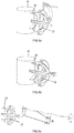
- the submerged filtration device 100 comprises a discharge valve 23, positioned on a bypass 24 of the first outlet duct 22 for example, by means of a tee ( figures 8a to 8d ).
- the discharge valve 23 is therefore subjected, on one side to the water pressure of the basin 200 and on the other side to the water pressure existing in the first outlet duct 22. Its role is to open to bypass the filtration device 100, in filtration mode, when the vacuum in the first outlet duct 22 reaches a certain threshold, said threshold being representative of at least partial clogging of the filtration device 200.
- the relief valve 23 may be in the form illustrated in figures 8a and 8b : the body of the relief valve 23 is held in the closed position by a calibrated spring.
- the body of the relief valve 23 moves towards the interior of the bypass 24, so as to let the water of the basin 200 enter. in the first outlet duct 22.
- the filtration device 100 is thus bypassed. Clogging of the latter therefore does not cause any deterioration, for example at the level of the pump, of the filtration system (which will be described in more detail below).
- a linkage 25 is associated with the relief valve 23 to allow manual operation of said valve 23 ( figures 8c and 8d ).
- the linkage 25 may include a rod 25a connected to a cam 25b which, by virtue of its shape and its axis of rotation, will press on the body of the discharge valve 23 when the rod 25a is pulled, then allowing the passage of the pool water in the first outlet pipe 22 and bypassing the filtration device 100 ( figure 8c ).
- the open position is maintained thanks to the shape of the cam 25b.
- the rod 25a is pushed back to release the hard point of the cam 25b, which releases the spring thus automatically closing the relief valve 23 ( figure 8d ).
- This variant is particularly advantageous for obtaining a maximum water flow rate in the case of the use of swimming against the current in the basin 200.
- the submerged filtration device 100 comprises a multi-hole valve 15 at the level of the second end 12 of the filtration bowl 10, between the floor filter 14 and the first outlet duct 22 ( figure 9a and 9b ).
- the multi-hole valve 15 In filtration mode, that is to say when the water circulates from the first end 11 of the filtration bowl 10 to its second end 12, the multi-hole valve 15 is configured to be in the open position and allow the passage of the filtered water from the filtration bowl 10 in the first outlet duct 22 ( figure 9a ).
- backwash mode that is to say when the water circulates from the second end 12 of the filtration bowl 10 to its first end 11, the multi-hole valve 15 is configured to be in the closed position.
- the water coming from the first pipe 22 and intended to pass through the filtration bowl 10 in order to clean it can then only pass through the orifices made in the body of the multi-hole valve 15.
- the orifices are uniformly distributed over the surface of the valve body. valve.
- the multi-hole valve 15 makes it possible to better channel and direct the flow of water coming from the first pipe 22: this makes it possible to clean the column of sand, without putting said sand in suspension.
- the design of the multi-hole valve 15 (diameter, number and positions of the orifices), based on the ratio of the open area (orifices) to the incoming water flow, ensures the cleaning power, without generating disturbance.
- the orifices may have a diameter of approximately 2 mm and form an open surface of between 3% and 20% of the surface of the valve body 15.
- the invention also relates to a filtration system 150 for a basin 200 comprising, on the one hand, an immersed filtration device 100 as described above, and on the other hand, a pumping device 110.
- the pumping device 110 comprises a pump 111, the first outlet pipe 22 for the filtered water, and the second delivery pipe 60 for the filtered water in the basin 200.
- the pump 111 has an inlet 111a, at the level of which the water is sucked, and an outlet 111b, at the level of which the water is delivered.
- the first outlet pipe 22 of the filtered water is connected to the second end of the filtration bowl 10.
- the second delivery pipe 60 is connected to a delivery nozzle 70 immersed in the basin 200 ( figures 6 and 7 ). Note that the filtration device 100 has been shown outside the basin 200 on the figures 6 and 7 to facilitate the visualization of the water circuits, while it is immersed in the water of the basin 200, as described above.
- the pump 111 comprises a speed variator.
- the variable speed drive allows the creation of optimized filtration and backwashing cycles, making it possible to increase the performance of the pump. filtration device 100, compared to a constant speed system.
- the motor of the pump 111 is of the “brushless” type.
- the technology of this type of motor is designed to eliminate contacts between fixed parts (stator) and moving parts (rotor), thus limiting friction and vibration and thereby reducing waste heat and wear of mechanical components.
- the use of a "brushless” motor makes it possible to consume approximately 10% to 20% less energy than a conventional asynchronous motor, with an equivalent flow rate, while ensuring power. superior to the asynchronous motor and having the advantage of having a constant operating torque from the start of the motor up to the steady state phase.
- the “brushless” motor can also make it possible to reduce the overall size of the pump 111.
- the pumping device 110 comprises a five-way valve 112.
- the connection configuration of the different channels 112a-112e with the other elements of the pumping device 110 allows the selective circulation of the water according to a filtration current or according to a counter -running.
- the pump 111 In a first configuration, where the first channel 112a is in communication with the fourth channel 112d, and the third channel 112c is in communication with the fifth channel 112e, the pump 111 generates a suction of water from the side of the second end 12 of the filtration bowl, which allows the water to circulate according to the filtration current.
- the water to be filtered EAF of the basin 200 collected by the submerged filtration device 100 at the level of the first end 11 of the filtration bowl 10, will pass through the opening 31 of the valve module 30, pass through the filtration bowl 10 to be filtered (EF), exit through the outlet pipe 22, and reach the delivery pipe 60 to finally be discharged into the basin 200 via the delivery nozzle 70 (circulation shown in solid lines on the figure 6 ).
- the pump 111 In a second configuration, where the second channel 112b is in communication with the fifth channel 112e, and the third channel 112c is in communication with the fourth channel 112d, the pump 111 generates a suction of the water from the basin 200 at the level of the delivery nozzle 70, which makes it possible to establish a circulation of water according to the backwashing back-flow. In fact, the water sucked in by the pump 111 is then discharged into the outlet pipe 22, then into the filtration bowl 10, against the current, from the second end 12 to the first end 11 (circulation illustrated in broken lines. on the figure 6 ).
- the backwash water will thus be loaded with particles related to the clogging of the elements of the filtration bowl 10 (floor filter 14, sand column, possibly sieve basket 13), as it passes through the filtration bowl 10 against the current. Due to the presence of the valve module 30, the backwashing water cannot pass through the first end 11 and be introduced into the basin; it is discharged through the drain pipe 40 located between the sieve basket 13 and the valve module 30.
- the pumping device 110 comprises two three-way valves 113,114.
- the connection configuration of the ways 113a, 113b, 113c of the first valve 113 and of the ways 114a, 114b, 114c of the second valve 114, with the other elements of the pumping device 110 allows the selective circulation of water according to a current filtration or against the current.
- the pump 111 In a first configuration of this second embodiment, where the first path 113a and the second path 113b of the first valve 113 are in communication, and where the first channel 114a and the third channel 114c are in communication, the pump 111 generates a suction of water via the outlet pipe 22, on the side of the second end 12 of the bowl filtration 10, which makes it possible to establish a circulation of water according to the filtration current.
- the water to be filtered EAF of the basin 200 collected by the submerged filtration device 100 at the level of the first end 11 of the filtration bowl 10, will pass through the opening 31 of the valve module 30, pass through the filtration bowl 10 to be filtered (EF), exit through the outlet pipe 22, and reach the delivery pipe 60 to be discharged into the basin 200 via the delivery nozzle 70 (circulation illustrated in solid line on the figure 7 ).
- the pump 111 In a second configuration, where the first channel 113a and the third channel 113c of the first valve 113 are in communication, and where the first channel 114a and the second channel 114b are in communication, the pump 111 generates a suction of water from the basin 200 at the level of the delivery nozzle 70, which makes it possible to establish a circulation of water according to the backwashing counter-current.
- the water sucked in by the pump 111 is then discharged into the outlet pipe 22, then into the filtration bowl 10, against the current, from the second end 12 to the first end 11.
- the backwash water goes thus take care of particles linked to the clogging of the elements of the filtration bowl 10 (floor filter 14, sand column, possibly sieve basket 13), as it passes through the filtration bowl 10 against the current . Due to the presence of the valve module 30, the backwashing water cannot pass through the first end 11 and be introduced into the basin; it is discharged through the drain pipe 40 located between the sieve basket 13 and the valve module 30.
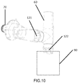
- the filtration system 150 comprises two safety valves 121, 122, automatic. , positioned on two branches communicating with the delivery duct 60, just before the delivery nozzle 70 ( figure 10 ).
- the two branches could for example be produced by a tee mounted on the delivery pipe 60.
- the first safety valve 121 on a first branch connected to the delivery nozzle 70, is configured to open when the water circulation is established according to the filtration current, that is to say when filtered water EF is delivered through said nozzle 70.
- the first safety valve 121 is furthermore configured to close when the water circulation is established according to the backwash backwash, that is to say when de the water in the basin is sucked in. This prevents any water aspiration directly via the nozzle 70.
- the second safety valve 122 is located on a second branch in communication with the interior of the shell or box 90 in which the filtration device 100 is held. This shell 90 being submerged, it contains the water from the basin 200.
- the second safety valve 122 is configured to close when the water circulation is established according to the filtration current, that is to say when EF filtered water arrives from the discharge pipe 60.
- the second safety valve 122 is also configured to open when the water circulation is established according to the backwash backwash: the water in the basin 200 is thus sucked in the interior of the shell 90, which is a space not directly accessible to users of the basin.
- the filtration system 150 comprising the submerged filtration device 100 and the pumping device 110 according to one or other of the embodiments described, constitutes an submerged filter system, compatible with backwashing. , thus limiting the steps of handling and manual washing of the filter elements, as usually done for submerged filters.
- the submerged filtration device 100 effectively prevents the backwashing of water from flowing back into the basin 200 thanks to the valve module 30 and allows this clogged water to be discharged through the drain pipe 40.
- the pumping device 110 offers an efficient and reliable solution for managing the circulation of water, according to a filtration current and according to a backwashing counter-current.
- the filtration system 150 can be used for any type of pond or swimming pool.
Landscapes
- Engineering & Computer Science (AREA)
- Architecture (AREA)
- Chemical & Material Sciences (AREA)
- Chemical Kinetics & Catalysis (AREA)
- Civil Engineering (AREA)
- Structural Engineering (AREA)
- Water Supply & Treatment (AREA)
- Filtration Of Liquid (AREA)
Claims (15)
- Tauchvorrichtung (100) zum Filtern des Wassers eines Beckens (200), umfassend eine Filtertrommel (10), die ein erstes Ende (11) zum Sammeln des zu filternden Wassers (EAF) aus dem Becken (200) und ein zweites Ende (12), das dazu bestimmt ist, mit einem ersten Auslassrohr (22) des gefilterten Wassers (EF) verbunden zu werden, aufweist, wobei die Vorrichtung (100) dadurch gekennzeichnet ist, dass sie umfasst:• ein Ventilmodul (30), das mit dem ersten Ende (11) der Filtertrommel (10) fest verbunden ist, um das Rückströmen des Wassers durch das erste Ende (11) während einer Rückspülung der Filtertrommel (10) zu blockieren;• ein Abflussrohr (40), das mit der Filtertrommel (10) in Verbindung steht, um während der Rückspülung das Wasser aus der Filtertrommel (10) abzulassen; und dadurch, dass:• die Filtertrommel (10) eine zylindrische Form hat,• und das Ventilmodul (30) ein Ventil (32) umfasst, das entlang einer Achse (33) parallel zur Achse der Filtertrommel (10) beweglich ist, um eine Ventilöffnung (31) freizugeben oder zu schließen, wobei der Durchmesser der Ventilöffnung (31) zwischen 50 % und 90 % des Durchmessers des Querschnitts der Filtertrommel (10) beträgt.
- Tauchvorrichtung zum Filtern (100) nach dem vorhergehenden Anspruch, wobei das Abflussrohr (40) ein Ventil zum Trockenlegen (41) umfasst.
- Tauchvorrichtung zum Filtern (100) nach einem der vorhergehenden Ansprüche, wobei die Filtertrommel (10) ein Sandfilter (1) ist und eine Sandsäule unter dem Ventilmodul (31) und einen Filterboden (14) umfasst, der mit seinem zweiten Ende (12) fest verbunden ist.
- Tauchvorrichtung zum Filtern (100) nach dem vorhergehenden Anspruch, wobei die Filtertrommel (10) einen Siebkorb (13) zwischen dem Ventilmodul (31) und der Sandsäule umfasst.
- Tauchvorrichtung zum Filtern (100) nach einem der beiden vorhergehenden Ansprüche, wobei der Filterboden (14) eine zylindrische Form aufweist und aus Edelstahl- oder Kunststoffdrähten besteht.
- Tauchvorrichtung zum Filtern (100) nach einem der drei vorhergehenden Ansprüche, umfassend ein Mehrlochventil (15), das eine Vielzahl von Öffnungen aufweist, das zwischen dem Filterboden (14) und dem ersten Auslassrohr (22) angeordnet ist, wobei das Ventil (15) so konfiguriert ist, dass es geöffnet ist, wenn sich die Filtervorrichtung (100) in einem Filtrationsmodus befindet, und dass es geschlossen ist, wenn sich die Vorrichtung (100) in einem Rückspülmodus befindet.
- Tauchvorrichtung zum Filtern (100) nach einem der vorhergehenden Ansprüche, umfassend einen am Ventilmodul (30) angeordneten Gitterkorb (50) zur Grobfiltration des Wassers.
- Tauchvorrichtung zum Filtern (100) nach einem der vorhergehenden Ansprüche, umfassend ein in einer Abzweigleitung (24) auf Höhe des ersten Auslassrohrs (22) angeordnetes Entlastungsventil (23) zum Umgehen der Filtertrommel (10).
- Tauchvorrichtung zum Filtern (100) nach dem vorhergehenden Anspruch, umfassend ein Gestänge (25) zum manuellen Betätigen des Entlastungsventils (23).
- Filtersystem (150) für ein Becken (200), umfassend:• eine Tauchvorrichtung zum Filtern (100) nach einem der vorhergehenden Ansprüche,• eine Pumpvorrichtung (110), umfassend eine Pumpe (111), das erste Auslassrohr (22) des gefilterten Wassers (EF) und ein zweites Rückströmrohr (60) des gefilterten Wassers (EF) in das Becken (200); wobei die Pumpvorrichtung (110) in der Lage ist, das Wasser zum Rückspülen der Filtertrommel (10) selektiv gemäß einem Filterstrom vom ersten (22) zum zweiten (60) Rohr oder gemäß einem Gegenstrom vom zweiten (60) zum ersten Rohr (22) umzuwälzen.
- Filtersystem (150) für ein Becken (200) nach dem vorhergehenden Anspruch, wobei die Pumpvorrichtung (110) ein Fünfwegeventil (112) umfasst, das die selektive Umwälzung von Wasser gemäß einem Filterstrom oder gemäß einem Gegenstrom ermöglicht.
- Filtersystem (150) für ein Becken nach Anspruch 11, wobei die Pumpvorrichtung (110) zwei Dreiwegeventile (113, 114) umfasst, die das selektive Umwälzen des Wassers gemäß einem Filterstrom oder gemäß einem Gegenstrom ermöglichen.
- Filtersystem (150) für ein Becken nach einem der drei vorhergehenden Ansprüche, wobei die Pumpe (111) einen Regelantrieb Drehzahlregler umfasst.
- Filtersystem (150) für ein Becken nach einem der vier vorhergehenden Ansprüche, wobei die Pumpe (111) einen "bürstenlosen" Motor umfasst.
- Filtersystem (150) für ein Becken nach einem der fünf vorhergehenden Ansprüche, umfassend zwei Sicherheitsventile (121, 122), die jeweils an zwei Zweigen eines T-Stücks positioniert sind, das an dem zweiten Rückströmrohr (60) angeordnet ist:• wobei das erste Sicherheitsventil (121) so konfiguriert ist, dass es sich öffnet, wenn die Wasserumwälzung gemäß einem Filterstrom hergestellt wird, wobei das zweite Sicherheitsventil (122) geschlossen ist,• wobei das zweite Sicherheitsventil (122) so konfiguriert ist, dass es sich öffnet, wenn die Wasserumwälzung gemäß einem Gegenstrom hergestellt wird, wobei das erste Sicherheitsventil (121) geschlossen ist.
Priority Applications (1)
| Application Number | Priority Date | Filing Date | Title |
|---|---|---|---|
| PL18827207T PL3717094T3 (pl) | 2017-11-30 | 2018-11-29 | Zanurzeniowe urządzenie filtrujące do basenu |
Applications Claiming Priority (2)
| Application Number | Priority Date | Filing Date | Title |
|---|---|---|---|
| FR1761434A FR3074057B1 (fr) | 2017-11-30 | 2017-11-30 | Dispositif immerge de filtration pour piscine |
| PCT/FR2018/053046 WO2019106307A1 (fr) | 2017-11-30 | 2018-11-29 | Dispositif immerge de filtration pour piscine |
Publications (2)
| Publication Number | Publication Date |
|---|---|
| EP3717094A1 EP3717094A1 (de) | 2020-10-07 |
| EP3717094B1 true EP3717094B1 (de) | 2021-11-03 |
Family
ID=61521634
Family Applications (1)
| Application Number | Title | Priority Date | Filing Date |
|---|---|---|---|
| EP18827207.4A Active EP3717094B1 (de) | 2017-11-30 | 2018-11-29 | Tauchfilter für ein schwimmbad |
Country Status (11)
| Country | Link |
|---|---|
| EP (1) | EP3717094B1 (de) |
| CN (1) | CN111542381B (de) |
| AU (1) | AU2018376937B2 (de) |
| CA (1) | CA3086663A1 (de) |
| ES (1) | ES2900537T3 (de) |
| FR (1) | FR3074057B1 (de) |
| MA (1) | MA51215A (de) |
| PL (1) | PL3717094T3 (de) |
| PT (1) | PT3717094T (de) |
| RU (1) | RU2770111C2 (de) |
| WO (1) | WO2019106307A1 (de) |
Family Cites Families (12)
| Publication number | Priority date | Publication date | Assignee | Title |
|---|---|---|---|---|
| US3616468A (en) * | 1970-03-26 | 1971-11-02 | John G Takacs | Swimming pool including integral filter |
| SU562293A1 (ru) * | 1974-05-30 | 1977-06-25 | Центральная Лаборатория Новых Видов Спасательной Техники Центрального Совета Всероссийского Общества Спасания На Водах (Освод Рсфср) | Фильтр дл очистки воды плавательных бассейнов |
| MXPA03011845A (es) * | 2001-06-19 | 2005-03-07 | Donald G Huber | Drenaje de piso con valvula de retencion. |
| EP1369544A1 (de) * | 2002-06-06 | 2003-12-10 | Eaux & Brevets Holding S.A. | Wasserbeckenfiltervorrichtung |
| EP1589165A1 (de) * | 2002-06-06 | 2005-10-26 | Eaux & Brevets Holding S.A. | Wasserbeckenfiltervorrichtung |
| CN2581624Y (zh) * | 2002-06-12 | 2003-10-22 | 江门威迪思泳池有限公司 | 分体式水循环过滤设备 |
| WO2012021935A1 (en) * | 2010-08-17 | 2012-02-23 | Ben Bremauer | Filtration device |
| WO2014128674A1 (en) | 2013-02-25 | 2014-08-28 | John Thomas Riedl | High efficiency, low-pressure filtration unit |
| CN103537139A (zh) * | 2013-10-25 | 2014-01-29 | 顾立新 | 一种简易型便携式过滤装置 |
| CN205806590U (zh) * | 2016-05-27 | 2016-12-14 | 张�杰 | 自动排水阀 |
| CN206483218U (zh) * | 2017-02-21 | 2017-09-12 | 上海康乾泳池技术有限公司 | 一种游泳池毛发过滤器 |
| CN107191015B (zh) * | 2017-05-25 | 2019-08-09 | 江苏亿美电器有限公司 | 一种浴用水池 |
-
2017
- 2017-11-30 FR FR1761434A patent/FR3074057B1/fr active Active
-
2018
- 2018-11-29 RU RU2020120658A patent/RU2770111C2/ru active
- 2018-11-29 ES ES18827207T patent/ES2900537T3/es active Active
- 2018-11-29 WO PCT/FR2018/053046 patent/WO2019106307A1/fr not_active Ceased
- 2018-11-29 PT PT188272074T patent/PT3717094T/pt unknown
- 2018-11-29 MA MA051215A patent/MA51215A/fr unknown
- 2018-11-29 AU AU2018376937A patent/AU2018376937B2/en not_active Ceased
- 2018-11-29 CA CA3086663A patent/CA3086663A1/fr active Pending
- 2018-11-29 CN CN201880084602.6A patent/CN111542381B/zh not_active Expired - Fee Related
- 2018-11-29 EP EP18827207.4A patent/EP3717094B1/de active Active
- 2018-11-29 PL PL18827207T patent/PL3717094T3/pl unknown
Also Published As
| Publication number | Publication date |
|---|---|
| CN111542381B (zh) | 2022-03-22 |
| MA51215A (fr) | 2021-06-02 |
| ES2900537T3 (es) | 2022-03-17 |
| FR3074057A1 (fr) | 2019-05-31 |
| PT3717094T (pt) | 2021-12-09 |
| AU2018376937A1 (en) | 2020-07-09 |
| WO2019106307A1 (fr) | 2019-06-06 |
| RU2020120658A3 (de) | 2021-12-30 |
| CA3086663A1 (fr) | 2019-06-06 |
| PL3717094T3 (pl) | 2022-01-17 |
| RU2020120658A (ru) | 2021-12-30 |
| FR3074057B1 (fr) | 2023-03-31 |
| AU2018376937B2 (en) | 2022-12-01 |
| EP3717094A1 (de) | 2020-10-07 |
| RU2770111C2 (ru) | 2022-04-14 |
| CN111542381A (zh) | 2020-08-14 |
Similar Documents
| Publication | Publication Date | Title |
|---|---|---|
| EP2554231B1 (de) | Sieb mit zylindrischem Filterpaneel für Wasserentnahmestelle | |
| EP3060731B1 (de) | Poolreiniger mit abnehmbarer filtrationsvorrichtung | |
| WO2016207572A1 (fr) | Systeme d'interception et de collecte de corps nettoyants par balayage alternatif | |
| FR2772635A1 (fr) | Dispositif autolavable de separation et de filtration de particules solides dans un debit de liquide et application a un circuit d'injection en carburant comportant un tel dispositif | |
| WO2014076098A1 (fr) | Dispositif de filtration d'eau de piscine | |
| FR2834317A1 (fr) | Pompe | |
| EP1381743A1 (de) | Verfahren zum filtern von schwimmbecken mit verstärker der wasserdurchflussmenge | |
| EP2239064B1 (de) | Reinigungsvorrichtung mit Kugeln für Wärmeaustauscher | |
| FR2871820A1 (fr) | Tamis a panneau filtrant circulaire pour prise d'eau | |
| FR2989596A1 (fr) | Appareil nettoyeur de surface immergee a filtration centripete | |
| EP0353154A1 (de) | Vorrichtung zum Abscheiden von abgeriebenen Reinigungskugeln aus Rohrbündeln | |
| EP2551004A1 (de) | Filtereinheit für Schwimmbad, und Filterkartusche für Filtereinheit eines Schwimmbads | |
| CA3086663A1 (fr) | Dispositif immerge de filtration pour piscine | |
| EP3099417B1 (de) | Vorrichtung zum filtern einer flüssigkeit durch zyklonische wirkung | |
| FR2946063A1 (fr) | Separateur de matieres, notamment pour poste de relevage d'eaux usees, et poste de relevage en comportant application. | |
| FR2835010A1 (fr) | Procede de circulation et nettoyage de l'eau de piscines, implantation d'un systeme pour la mise en oeuvre du procede et multiplicateur de debit adapte | |
| FR2855432A1 (fr) | Groupe de filtration et d'entretien pour piscine | |
| FR2877856A1 (fr) | Ensemble de filtration d'eau pour piscine, et ensemble a cartouche et panier | |
| EP4111046B1 (de) | Filtrationsanordnung und verwendung eine filtrationsvorrichtung mit anti-blasen-funktion, um wasser zu reinigen, das für eine verbrennungskammer eines fahrzeugs bestimmt ist | |
| EP1752207A1 (de) | Filtervorrichtung mit integriertem Umlaufsystem und Umlaufpumpe | |
| EP4023873B1 (de) | Filteranordnung und verwendung einer filtervorrichtung zur reinigung von wasser, das für eine brennkammer eines fahrzeugs bestimmt ist | |
| WO2009115733A2 (fr) | Procede et systeme de filtration de l'eau d'un bassin de piscine | |
| EP2236701B1 (de) | Einordnungssystem eines Roboters in einem Schwimmbad | |
| FR3151033A3 (fr) | Système de filtration d’eau | |
| EP4717888A1 (de) | Sammel- und lagereinheit mit getriebeölgehäuse und ölhebeventilen |
Legal Events
| Date | Code | Title | Description |
|---|---|---|---|
| STAA | Information on the status of an ep patent application or granted ep patent |
Free format text: STATUS: UNKNOWN |
|
| STAA | Information on the status of an ep patent application or granted ep patent |
Free format text: STATUS: THE INTERNATIONAL PUBLICATION HAS BEEN MADE |
|
| PUAI | Public reference made under article 153(3) epc to a published international application that has entered the european phase |
Free format text: ORIGINAL CODE: 0009012 |
|
| STAA | Information on the status of an ep patent application or granted ep patent |
Free format text: STATUS: REQUEST FOR EXAMINATION WAS MADE |
|
| 17P | Request for examination filed |
Effective date: 20200527 |
|
| AK | Designated contracting states |
Kind code of ref document: A1 Designated state(s): AL AT BE BG CH CY CZ DE DK EE ES FI FR GB GR HR HU IE IS IT LI LT LU LV MC MK MT NL NO PL PT RO RS SE SI SK SM TR |
|
| AX | Request for extension of the european patent |
Extension state: BA ME |
|
| DAX | Request for extension of the european patent (deleted) | ||
| RAV | Requested validation state of the european patent: fee paid |
Extension state: MA Effective date: 20200618 |
|
| GRAP | Despatch of communication of intention to grant a patent |
Free format text: ORIGINAL CODE: EPIDOSNIGR1 |
|
| STAA | Information on the status of an ep patent application or granted ep patent |
Free format text: STATUS: GRANT OF PATENT IS INTENDED |
|
| INTG | Intention to grant announced |
Effective date: 20210628 |
|
| RAP3 | Party data changed (applicant data changed or rights of an application transferred) |
Owner name: PISCINES DESJOYAUX SA |
|
| RIN1 | Information on inventor provided before grant (corrected) |
Inventor name: BONNEFOY, SERGE Inventor name: DEJEY, MARC Inventor name: DESJOYAUX, JEAN-LOUIS |
|
| GRAS | Grant fee paid |
Free format text: ORIGINAL CODE: EPIDOSNIGR3 |
|
| GRAA | (expected) grant |
Free format text: ORIGINAL CODE: 0009210 |
|
| STAA | Information on the status of an ep patent application or granted ep patent |
Free format text: STATUS: THE PATENT HAS BEEN GRANTED |
|
| AK | Designated contracting states |
Kind code of ref document: B1 Designated state(s): AL AT BE BG CH CY CZ DE DK EE ES FI FR GB GR HR HU IE IS IT LI LT LU LV MC MK MT NL NO PL PT RO RS SE SI SK SM TR |
|
| REG | Reference to a national code |
Ref country code: GB Ref legal event code: FG4D Free format text: NOT ENGLISH |
|
| REG | Reference to a national code |
Ref country code: AT Ref legal event code: REF Ref document number: 1443459 Country of ref document: AT Kind code of ref document: T Effective date: 20211115 Ref country code: CH Ref legal event code: EP |
|
| REG | Reference to a national code |
Ref country code: DE Ref legal event code: R096 Ref document number: 602018026232 Country of ref document: DE |
|
| REG | Reference to a national code |
Ref country code: IE Ref legal event code: FG4D Free format text: LANGUAGE OF EP DOCUMENT: FRENCH |
|
| REG | Reference to a national code |
Ref country code: PT Ref legal event code: SC4A Ref document number: 3717094 Country of ref document: PT Date of ref document: 20211209 Kind code of ref document: T Free format text: AVAILABILITY OF NATIONAL TRANSLATION Effective date: 20211202 |
|
| REG | Reference to a national code |
Ref country code: NL Ref legal event code: FP |
|
| REG | Reference to a national code |
Ref country code: GR Ref legal event code: EP Ref document number: 20210403160 Country of ref document: GR Effective date: 20220113 |
|
| REG | Reference to a national code |
Ref country code: LT Ref legal event code: MG9D |
|
| REG | Reference to a national code |
Ref country code: ES Ref legal event code: FG2A Ref document number: 2900537 Country of ref document: ES Kind code of ref document: T3 Effective date: 20220317 |
|
| PG25 | Lapsed in a contracting state [announced via postgrant information from national office to epo] |
Ref country code: RS Free format text: LAPSE BECAUSE OF FAILURE TO SUBMIT A TRANSLATION OF THE DESCRIPTION OR TO PAY THE FEE WITHIN THE PRESCRIBED TIME-LIMIT Effective date: 20211103 Ref country code: LT Free format text: LAPSE BECAUSE OF FAILURE TO SUBMIT A TRANSLATION OF THE DESCRIPTION OR TO PAY THE FEE WITHIN THE PRESCRIBED TIME-LIMIT Effective date: 20211103 Ref country code: FI Free format text: LAPSE BECAUSE OF FAILURE TO SUBMIT A TRANSLATION OF THE DESCRIPTION OR TO PAY THE FEE WITHIN THE PRESCRIBED TIME-LIMIT Effective date: 20211103 Ref country code: BG Free format text: LAPSE BECAUSE OF FAILURE TO SUBMIT A TRANSLATION OF THE DESCRIPTION OR TO PAY THE FEE WITHIN THE PRESCRIBED TIME-LIMIT Effective date: 20220203 |
|
| PG25 | Lapsed in a contracting state [announced via postgrant information from national office to epo] |
Ref country code: IS Free format text: LAPSE BECAUSE OF FAILURE TO SUBMIT A TRANSLATION OF THE DESCRIPTION OR TO PAY THE FEE WITHIN THE PRESCRIBED TIME-LIMIT Effective date: 20220303 Ref country code: SE Free format text: LAPSE BECAUSE OF FAILURE TO SUBMIT A TRANSLATION OF THE DESCRIPTION OR TO PAY THE FEE WITHIN THE PRESCRIBED TIME-LIMIT Effective date: 20211103 Ref country code: NO Free format text: LAPSE BECAUSE OF FAILURE TO SUBMIT A TRANSLATION OF THE DESCRIPTION OR TO PAY THE FEE WITHIN THE PRESCRIBED TIME-LIMIT Effective date: 20220203 Ref country code: LV Free format text: LAPSE BECAUSE OF FAILURE TO SUBMIT A TRANSLATION OF THE DESCRIPTION OR TO PAY THE FEE WITHIN THE PRESCRIBED TIME-LIMIT Effective date: 20211103 Ref country code: HR Free format text: LAPSE BECAUSE OF FAILURE TO SUBMIT A TRANSLATION OF THE DESCRIPTION OR TO PAY THE FEE WITHIN THE PRESCRIBED TIME-LIMIT Effective date: 20211103 |
|
| PG25 | Lapsed in a contracting state [announced via postgrant information from national office to epo] |
Ref country code: SM Free format text: LAPSE BECAUSE OF FAILURE TO SUBMIT A TRANSLATION OF THE DESCRIPTION OR TO PAY THE FEE WITHIN THE PRESCRIBED TIME-LIMIT Effective date: 20211103 Ref country code: SK Free format text: LAPSE BECAUSE OF FAILURE TO SUBMIT A TRANSLATION OF THE DESCRIPTION OR TO PAY THE FEE WITHIN THE PRESCRIBED TIME-LIMIT Effective date: 20211103 Ref country code: RO Free format text: LAPSE BECAUSE OF FAILURE TO SUBMIT A TRANSLATION OF THE DESCRIPTION OR TO PAY THE FEE WITHIN THE PRESCRIBED TIME-LIMIT Effective date: 20211103 Ref country code: LU Free format text: LAPSE BECAUSE OF NON-PAYMENT OF DUE FEES Effective date: 20211129 Ref country code: EE Free format text: LAPSE BECAUSE OF FAILURE TO SUBMIT A TRANSLATION OF THE DESCRIPTION OR TO PAY THE FEE WITHIN THE PRESCRIBED TIME-LIMIT Effective date: 20211103 Ref country code: DK Free format text: LAPSE BECAUSE OF FAILURE TO SUBMIT A TRANSLATION OF THE DESCRIPTION OR TO PAY THE FEE WITHIN THE PRESCRIBED TIME-LIMIT Effective date: 20211103 |
|
| REG | Reference to a national code |
Ref country code: DE Ref legal event code: R097 Ref document number: 602018026232 Country of ref document: DE |
|
| PG25 | Lapsed in a contracting state [announced via postgrant information from national office to epo] |
Ref country code: MC Free format text: LAPSE BECAUSE OF FAILURE TO SUBMIT A TRANSLATION OF THE DESCRIPTION OR TO PAY THE FEE WITHIN THE PRESCRIBED TIME-LIMIT Effective date: 20211103 |
|
| PLBE | No opposition filed within time limit |
Free format text: ORIGINAL CODE: 0009261 |
|
| STAA | Information on the status of an ep patent application or granted ep patent |
Free format text: STATUS: NO OPPOSITION FILED WITHIN TIME LIMIT |
|
| 26N | No opposition filed |
Effective date: 20220804 |
|
| PG25 | Lapsed in a contracting state [announced via postgrant information from national office to epo] |
Ref country code: IE Free format text: LAPSE BECAUSE OF NON-PAYMENT OF DUE FEES Effective date: 20211129 Ref country code: AL Free format text: LAPSE BECAUSE OF FAILURE TO SUBMIT A TRANSLATION OF THE DESCRIPTION OR TO PAY THE FEE WITHIN THE PRESCRIBED TIME-LIMIT Effective date: 20211103 |
|
| PG25 | Lapsed in a contracting state [announced via postgrant information from national office to epo] |
Ref country code: SI Free format text: LAPSE BECAUSE OF FAILURE TO SUBMIT A TRANSLATION OF THE DESCRIPTION OR TO PAY THE FEE WITHIN THE PRESCRIBED TIME-LIMIT Effective date: 20211103 |
|
| REG | Reference to a national code |
Ref country code: AT Ref legal event code: UEP Ref document number: 1443459 Country of ref document: AT Kind code of ref document: T Effective date: 20211103 |
|
| PG25 | Lapsed in a contracting state [announced via postgrant information from national office to epo] |
Ref country code: CY Free format text: LAPSE BECAUSE OF FAILURE TO SUBMIT A TRANSLATION OF THE DESCRIPTION OR TO PAY THE FEE WITHIN THE PRESCRIBED TIME-LIMIT Effective date: 20211103 |
|
| PG25 | Lapsed in a contracting state [announced via postgrant information from national office to epo] |
Ref country code: HU Free format text: LAPSE BECAUSE OF FAILURE TO SUBMIT A TRANSLATION OF THE DESCRIPTION OR TO PAY THE FEE WITHIN THE PRESCRIBED TIME-LIMIT; INVALID AB INITIO Effective date: 20181129 |
|
| PGFP | Annual fee paid to national office [announced via postgrant information from national office to epo] |
Ref country code: NL Payment date: 20231120 Year of fee payment: 6 |
|
| PGFP | Annual fee paid to national office [announced via postgrant information from national office to epo] |
Ref country code: GB Payment date: 20231123 Year of fee payment: 6 Ref country code: GR Payment date: 20231121 Year of fee payment: 6 |
|
| PGFP | Annual fee paid to national office [announced via postgrant information from national office to epo] |
Ref country code: TR Payment date: 20231127 Year of fee payment: 6 Ref country code: PT Payment date: 20231116 Year of fee payment: 6 Ref country code: IT Payment date: 20231124 Year of fee payment: 6 Ref country code: DE Payment date: 20231121 Year of fee payment: 6 Ref country code: CZ Payment date: 20231121 Year of fee payment: 6 Ref country code: CH Payment date: 20231202 Year of fee payment: 6 Ref country code: AT Payment date: 20231121 Year of fee payment: 6 |
|
| PGFP | Annual fee paid to national office [announced via postgrant information from national office to epo] |
Ref country code: PL Payment date: 20231019 Year of fee payment: 6 Ref country code: BE Payment date: 20231120 Year of fee payment: 6 |
|
| PGFP | Annual fee paid to national office [announced via postgrant information from national office to epo] |
Ref country code: ES Payment date: 20240130 Year of fee payment: 6 |
|
| PG25 | Lapsed in a contracting state [announced via postgrant information from national office to epo] |
Ref country code: MK Free format text: LAPSE BECAUSE OF FAILURE TO SUBMIT A TRANSLATION OF THE DESCRIPTION OR TO PAY THE FEE WITHIN THE PRESCRIBED TIME-LIMIT Effective date: 20211103 |
|
| VS25 | Lapsed in a validation state [announced via postgrant information from nat. office to epo] |
Ref country code: MA Free format text: LAPSE BECAUSE OF FAILURE TO SUBMIT A TRANSLATION OF THE DESCRIPTION OR TO PAY THE FEE WITHIN THE PRESCRIBED TIME-LIMIT Effective date: 20211103 |
|
| PG25 | Lapsed in a contracting state [announced via postgrant information from national office to epo] |
Ref country code: MT Free format text: LAPSE BECAUSE OF FAILURE TO SUBMIT A TRANSLATION OF THE DESCRIPTION OR TO PAY THE FEE WITHIN THE PRESCRIBED TIME-LIMIT Effective date: 20211103 |
|
| REG | Reference to a national code |
Ref country code: DE Ref legal event code: R119 Ref document number: 602018026232 Country of ref document: DE |
|
| REG | Reference to a national code |
Ref country code: CH Ref legal event code: PL |
|
| REG | Reference to a national code |
Ref country code: NL Ref legal event code: MM Effective date: 20241201 |
|
| REG | Reference to a national code |
Ref country code: AT Ref legal event code: MM01 Ref document number: 1443459 Country of ref document: AT Kind code of ref document: T Effective date: 20241129 Ref country code: CH Ref legal event code: PL |
|
| PG25 | Lapsed in a contracting state [announced via postgrant information from national office to epo] |
Ref country code: PT Free format text: LAPSE BECAUSE OF NON-PAYMENT OF DUE FEES Effective date: 20250529 |
|
| PG25 | Lapsed in a contracting state [announced via postgrant information from national office to epo] |
Ref country code: GR Free format text: LAPSE BECAUSE OF NON-PAYMENT OF DUE FEES Effective date: 20250610 |
|
| GBPC | Gb: european patent ceased through non-payment of renewal fee |
Effective date: 20241129 |
|
| PG25 | Lapsed in a contracting state [announced via postgrant information from national office to epo] |
Ref country code: CH Free format text: LAPSE BECAUSE OF NON-PAYMENT OF DUE FEES Effective date: 20241130 |
|
| PG25 | Lapsed in a contracting state [announced via postgrant information from national office to epo] |
Ref country code: AT Free format text: LAPSE BECAUSE OF NON-PAYMENT OF DUE FEES Effective date: 20241129 |
|
| PG25 | Lapsed in a contracting state [announced via postgrant information from national office to epo] |
Ref country code: CZ Free format text: LAPSE BECAUSE OF NON-PAYMENT OF DUE FEES Effective date: 20241129 |
|
| PG25 | Lapsed in a contracting state [announced via postgrant information from national office to epo] |
Ref country code: NL Free format text: LAPSE BECAUSE OF NON-PAYMENT OF DUE FEES Effective date: 20241201 |
|
| REG | Reference to a national code |
Ref country code: BE Ref legal event code: MM Effective date: 20241130 |
|
| PG25 | Lapsed in a contracting state [announced via postgrant information from national office to epo] |
Ref country code: DE Free format text: LAPSE BECAUSE OF NON-PAYMENT OF DUE FEES Effective date: 20250603 |
|
| PG25 | Lapsed in a contracting state [announced via postgrant information from national office to epo] |
Ref country code: IT Free format text: LAPSE BECAUSE OF NON-PAYMENT OF DUE FEES Effective date: 20241129 |
|
| PG25 | Lapsed in a contracting state [announced via postgrant information from national office to epo] |
Ref country code: GB Free format text: LAPSE BECAUSE OF NON-PAYMENT OF DUE FEES Effective date: 20241129 Ref country code: BE Free format text: LAPSE BECAUSE OF NON-PAYMENT OF DUE FEES Effective date: 20241130 |
|
| REG | Reference to a national code |
Ref country code: ES Ref legal event code: FD2A Effective date: 20260105 |
|
| PGFP | Annual fee paid to national office [announced via postgrant information from national office to epo] |
Ref country code: FR Payment date: 20251126 Year of fee payment: 8 |
|
| PG25 | Lapsed in a contracting state [announced via postgrant information from national office to epo] |
Ref country code: ES Free format text: LAPSE BECAUSE OF NON-PAYMENT OF DUE FEES Effective date: 20241130 |
|
| PG25 | Lapsed in a contracting state [announced via postgrant information from national office to epo] |
Ref country code: PL Free format text: LAPSE BECAUSE OF NON-PAYMENT OF DUE FEES Effective date: 20241129 |
|
| PG25 | Lapsed in a contracting state [announced via postgrant information from national office to epo] |
Ref country code: TR Free format text: LAPSE BECAUSE OF NON-PAYMENT OF DUE FEES Effective date: 20241129 |