EP3718461A1 - Lave-vaisselle, en particulier lave-vaisselle électroménager - Google Patents
Lave-vaisselle, en particulier lave-vaisselle électroménager Download PDFInfo
- Publication number
- EP3718461A1 EP3718461A1 EP20167690.5A EP20167690A EP3718461A1 EP 3718461 A1 EP3718461 A1 EP 3718461A1 EP 20167690 A EP20167690 A EP 20167690A EP 3718461 A1 EP3718461 A1 EP 3718461A1
- Authority
- EP
- European Patent Office
- Prior art keywords
- air
- tank
- circuit
- dishwasher
- washing
- Prior art date
- Legal status (The legal status is an assumption and is not a legal conclusion. Google has not performed a legal analysis and makes no representation as to the accuracy of the status listed.)
- Granted
Links
Images


Classifications
-
- A—HUMAN NECESSITIES
- A47—FURNITURE; DOMESTIC ARTICLES OR APPLIANCES; COFFEE MILLS; SPICE MILLS; SUCTION CLEANERS IN GENERAL
- A47L—DOMESTIC WASHING OR CLEANING; SUCTION CLEANERS IN GENERAL
- A47L15/00—Washing or rinsing machines for crockery or tableware
- A47L15/42—Details
- A47L15/4291—Recovery arrangements, e.g. for the recovery of energy or water
-
- A—HUMAN NECESSITIES
- A47—FURNITURE; DOMESTIC ARTICLES OR APPLIANCES; COFFEE MILLS; SPICE MILLS; SUCTION CLEANERS IN GENERAL
- A47L—DOMESTIC WASHING OR CLEANING; SUCTION CLEANERS IN GENERAL
- A47L15/00—Washing or rinsing machines for crockery or tableware
- A47L15/42—Details
- A47L15/48—Drying arrangements
- A47L15/486—Blower arrangements
-
- Y—GENERAL TAGGING OF NEW TECHNOLOGICAL DEVELOPMENTS; GENERAL TAGGING OF CROSS-SECTIONAL TECHNOLOGIES SPANNING OVER SEVERAL SECTIONS OF THE IPC; TECHNICAL SUBJECTS COVERED BY FORMER USPC CROSS-REFERENCE ART COLLECTIONS [XRACs] AND DIGESTS
- Y02—TECHNOLOGIES OR APPLICATIONS FOR MITIGATION OR ADAPTATION AGAINST CLIMATE CHANGE
- Y02B—CLIMATE CHANGE MITIGATION TECHNOLOGIES RELATED TO BUILDINGS, e.g. HOUSING, HOUSE APPLIANCES OR RELATED END-USER APPLICATIONS
- Y02B30/00—Energy efficient heating, ventilation or air conditioning [HVAC]
- Y02B30/52—Heat recovery pumps, i.e. heat pump based systems or units able to transfer the thermal energy from one area of the premises or part of the facilities to a different one, improving the overall efficiency
Definitions
- the invention relates to a dishwasher, in particular in the embodiment of a domestic dishwasher, with a washing compartment providing a washing area which is used to hold items to be cleaned, and with a heat pump device which has an evaporator which is arranged within a tank filled with water.
- the invention also relates to a method for operating a dishwasher.
- a dishwasher of the generic type has a washing container that provides a washing area. This is accessible on the user side via a loading opening, which can be closed in a fluid-tight manner by means of a pivotably mounted wash cabinet door.
- the washing container is used to hold items to be cleaned, which can be, for example, dishes, cutlery and / or the like.
- the dishwasher has a spray device in the interior of the washing compartment for the application of washing liquid to be cleaned, the so-called washing liquor.
- This spray device typically provides rotatably mounted spray arms, two or three such spray arms being provided as a rule. When used as intended, the items to be cleaned are exposed to washing liquid by means of rotating spray arms.
- a dishwasher of the generic type has a heat pump device.
- Such a heat pump device can either be an air-water heat pump device or be designed as a water-water heat pump device.
- the generic dishwasher according to the EP 3 375 345 A1 has a water-to-water heat pump facility.
- a water-water heat pump device has, in a manner known per se, an evaporator, a compressor, a condenser and a flow or circulation circuit which fluidically connects these components to one another.
- the condenser serves as a heat exchanger by means of which thermal energy is transferred from a working medium circulated in the flow circuit of the heat pump device to the washing solution.
- the evaporator of a water-to-water heat pump device is arranged within a tank that is preferably filled with water.
- thermal energy is withdrawn from the water stored in the tank, which is transferred to the working medium carried in the flow circuit of the heat pump device and is thus used to heat the washing solution.
- the extraction of heat energy from the water leads to the water being cooled down to the point of freezing it.
- the tank is fluidically connected to an air duct and to an air discharge duct, the air supply duct and the air discharge duct opening into the washing chamber at the other end.
- This construction makes it possible, if necessary, to remove air from the air through the air supply duct Pump the wash cabinet out into the tank.
- the air comes into direct contact with the contents of the tank, namely the liquid or partially frozen or ice-shaped water stored therein; so it flows directly along the water and / or ice surface.
- the air discharge channel is used to convey air from the tank back into the wash cabinet.
- a circulating air circuit is created that allows air to be circulated during operation, namely from the washing area through the air supply duct into the tank and from there through the air discharge duct back into the washing area.
- thermal energy can be transferred from the air accommodated by the washing compartment to the water in the tank, which leads to faster regeneration of the water and therefore to a more rapid increase in the temperature of the water to the minimum temperature required for proper operation of the heat pump device.
- the EP 3 375 345 A1 known construction has proven itself in everyday practical use, there is a need for improvement.
- the aim is to achieve an even more efficient regeneration of the water stored in the tank, so that the idle time between two subsequent wash programs can be shortened even further when the heat pump device is used as intended. It is therefore the object of the invention to further develop a dishwasher of the type mentioned at the outset such that an even further improved tank regeneration is possible structurally.
- the invention proposes a dishwasher of the type mentioned at the outset, which is characterized by a circulating air system that has an air circulation system and a fan unit arranged within the air circulation system, the air circulation system at least in sections on an outer surface of both the washing compartment and the tank is passed by, so that when the fan unit is operating, the washing compartment and the tank are at least partially air-washed, the air guided in the air circulation circuit being in direct contact with the outer surfaces of the washing compartment and the tank.
- an air duct is not provided through the washing compartment and the tank, but around the tank and the washing compartment.
- the dishwasher according to the invention has a circulating air system with an air circulation circuit that both is guided past an outer surface of the washing container as well as an outer surface of the tank at least in sections.
- both the washing compartment and the tank are thus at least partially surrounded by air, the air guided in the air circulation circuit being in direct contact with the respective outer surfaces of the washing compartment on the one hand and the tank on the other.
- the construction according to the invention proves to be compared to the construction according to EP 3 375 345 A1 particularly advantageous for the following reasons.
- the available effective surface for heat exchange is significantly increased. So is used in the construction according to the EP 3 375 345 A1 only the water surface of the water stored in the tank as a heat exchange surface.
- the embodiment according to the invention provides for air to circulate around the tank, so that the side surfaces of the tank are also used for heat exchange.
- the enlargement of the effective surface area for heat exchange achieved in this way advantageously leads to a significantly reduced regeneration time.
- the water stored in the tank is thus brought to the minimum temperature required for the intended use of the heat pump device much more quickly.
- the heat pump device When the heat pump device is used as intended, it is generally unavoidable that condensate will form on the outer surface of the tank, even if the tank is insulated.
- the air circulation according to the construction according to the invention advantageously ensures that such a condensate dries off, so that, contrary to the prior art, condensate puddles cannot unintentionally form in the base area of the dishwasher.
- Another advantage of the embodiment according to the invention is that no moisture can be introduced into the tank from the washing area.
- the water level in the tank can thus be kept constant and thus at an optimized working level.
- a circulating air system is provided overall which enables air to circulate around the washing compartment on the one hand and the tank on the other hand.
- the washing container which is warmed up as a result of a washing program and / or washing program step carried out as intended, heats the air flowing around it.
- the air heated in this way is circulated in the circulating air circuit and also flows around the tank of the heat pump device. In this way, the tank and thus also the water stored in it are heated.
- the air that has cooled down as a result of the tank heating is returned to the rinsing container in the circulating air system, where it is heated again.
- the air in the air circulation system of the circulating air system is circulated, ie in circulation mode, so that there is constant heat transfer between the washing compartment and air on the one hand and air and tank on the other. Since in comparison to the prior art in particular after EP 3 375 345 A1 If an overall enlarged heat exchanger surface is available, a more efficient and thus faster heat input into the water stored by the tank with the aim of faster heating of the same to the minimum temperature required for proper operation of the heat pump device can be achieved.
- the air guiding circuit is at least partially limited by a housing accommodating the washing compartment and the tank.
- a dishwasher of the generic type typically has a housing that houses both the washing compartment and the tank.
- the housing provides a volume space which is not completely filled by the washing container, the tank and other structural components of the dishwasher. In the simplest embodiment of the invention, this volume space is used as an air guiding circuit.
- the air circulation circuit is at least partially limited by the housing housing the washing compartment and the tank. If the dishwasher is designed as a device to be integrated into a kitchen unit and has a housing that is open at the top, the air guidance circuit is through the housing on the top limiting cover, for example a countertop of a kitchen unit.
- a corresponding duct guide at least in the base area of the dishwasher. It is particularly preferred to provide a corresponding channel guide for deflecting the air from the base area into the rear and / or side area of the washing compartment.
- the air guiding circuit surrounds the washing container and / or the tank in a circumferential or at least partially circumferential manner.
- the air guiding circuit is therefore preferably designed such that at least one circumferential flushing of both the washing compartment and the tank is provided from a first side, for example the respective rear side to a second, the first opposite side, for example to the respective front side and back again.
- a first side for example the back
- the top a second side opposite the first side (for example the front) and the underside of both the washing compartment and the tank are air-washed.
- an air guiding circuit can be provided, accordingly the side walls are also flushed with air, in particular the side walls of the tank.
- the heat transfer surface is thus increased even further, which further optimizes the heat transfer from the washing compartment to the water in the tank.
- the tank is arranged over the entire surface or at least largely over the entire surface within the air duct. This optimizes the heat exchanger surface with respect to the tank, so that an efficient heat transfer can take place from the warmed air coming from the washing compartment to the water stored in the tank.
- the tank has a container and an insulation formed on the outside of the container, the insulation providing the outside of the tank.
- the tank has a container, which is used for the actual water supply, and an insulation that surrounds the container on the outside of the container.
- the tank equipped with insulation represents the tank, the outside of the tank being provided by the insulation.
- the air circulating around the tank according to the invention condensate drying is achieved, so that an undesirable accumulation of condensate in the base area of the dishwasher is minimized and possibly even avoided.
- the air duct is delimited at least in sections by air ducting means, in particular metal sheets or plastic profiles.
- air ducts are used, in particular in the base area of the dishwasher, which limit the air duct circuit.
- Such air ducts are preferably formed from sheet metal, in particular sheet metal, or plastic.
- An advantage of such air ducts is a targeted flow of the air circulated in the air duct.
- Such forced air guidance is particularly advantageous in the base area of the dishwasher, since otherwise uncontrolled air currents and turbulence can occur here due to the structural components of the dishwasher located in the base area.
- Targeted air routing by means of a corresponding air routing channel provides a remedy here, which also leads to an optimized heat input into the water stored in the tank.
- the washing compartment has ribs protruding into the air duct on the outside. Such ribs create an enlargement of the heat transfer surface provided by the washing compartment. In this way, improved heat input from the heated washing compartment into the air flowing around the washing compartment is achieved.
- the air duct is fluidically connected to an air inlet opening. This allows fresh air to be introduced from the outside into the air circulated in the air flow circuit. This allows an additional control of the humidity of the circulated air in the air circulation Air.
- the air guiding circuit is fluidically connected to an air outlet opening.
- a bypass system is proposed that allows fresh air to flow into the air duct or air circulated in the air duct to the outside into the atmosphere surrounding the dishwasher.
- Such a bypass system is particularly advantageous in order to dilute and / or accelerate the vapors emerging from the wash cabinet after an automatic wash cabinet door has been opened into the atmosphere surrounding the dishwasher and / or to preheat and / or warm up a worktop protruding from the front of the dishwasher.
- the air inlet opening and / or the air outlet opening can each be transferred from an open position to a closed position and vice versa by means of a closure means. This makes it possible either to circulate air in the air guidance circuit and / or optionally to introduce fresh air into the air guidance circuit or to let air out of it into the atmosphere surrounding the dishwasher.
- the air inlet opening and / or the air outlet opening are closed by means of corresponding closing means, which are preferably moved in a sensor-controlled motorized manner.
- a fully automatic operation of the closure means is thus permitted and this preferably as a function of the progress of a running washing program.
- the invention also proposes a method for operating a dishwasher of the type according to the invention in order to achieve the above object, in which the fan unit is switched on and air is guided through the air duct at the start of drying of the washware.
- the washware starts to dry
- the still comparatively warm wash container is used to transfer heat energy from the wash container to the air circulated in the air circulation system, so that the tank of the heat pump device is then heated in the manner described above with the aim can, the water stored in it to regenerate as quickly as possible. In this way, part of the thermal energy previously used by heating the wash liquor is recovered.
- the circulating air mode that is to say the routing of air through the air routing circuit, continues to be operated even after a washing program has been completed.
- This continued operation is advantageous because a wash program can regularly be brought to an end as intended when the items to be washed in the wash cabinet are still warm, at least warmer than the room air surrounding the dishwasher.
- the thermal energy still present in the still heated wash ware or in the heated wash container would remain unused if the circulating air mode were also stopped at the end of a wash program. It is therefore provided according to the invention that the fan unit continues to be operated even after a wash program has been completed, in order to be able to use this residual amount of heat in the system.
- the fan unit is also operated after an automatic opening of a washing chamber door that closes a loading opening of the washing container. This makes it possible, in the manner already described, to dilute vapors emerging from a washing container and / or to preheat and / or warm up a worktop of a kitchen unit protruding from the front of the dishwasher on the underside before the washing chamber door is opened.
- the fan unit is designed to be speed controllable.
- the speed of the fan unit can be set or adjusted by the control of the dishwasher as a function of one or more sensor-recorded values of a parameter characterizing the air flow in the air flow circuit and / or the heat pump device and / or the water in the tank and / or the water in the washing compartment. be managed.
- the speed regulation can take place, for example, as a function of the speed of the air flow, the temperature of the air in the air flow, the temperature of the water stored in the tank and / or a water or air temperature in the collecting pot.
- a circulating air duct according to the invention offers the overall advantage of a reduced risk of contamination compared to drawing in fresh air from the Surroundings.
- an improvement in the heat flow is achieved by flowing around the entire evaporator tank, whereby the overall regeneration time can be shortened.
- it is advantageously possible to control the speed of the fan unit for example depending on operating parameters detected by sensors, such as temperature of the circulated air, temperature of the ambient air, temperature of the water stored in the tank, level of the water stored in the tank, air flow speed and / or the like. This allows an optimized process sequence with the aim of optimized heat transfer into the water stored in the tank, so that a regeneration time is achieved that is significantly shorter than in the prior art.
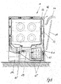
- Fig. 1 shows a dishwasher 1 according to the invention in a purely schematic representation.
- the dishwasher 1 has, in a manner known per se, a housing 2 which provides a volume space 5 and among other things houses a washing compartment 3 and a heat pump device 10.
- the washing compartment 3 in turn provides a washing area 4 which, when used as intended, serves to hold items 6 to be cleaned.
- a spray device (not shown in more detail in the figures), which is arranged inside the washing compartment 3, is used to load wash ware 6 to be cleaned with wash liquor.
- a spray device preferably has spray arms which are each rotatably arranged within the washing compartment 3.
- washing racks 7 are used to accommodate the items to be cleaned 6, with three such washing racks 7 being provided.
- the washing chamber 4 opens into a collecting pot 8 of the washing container 3, not shown in any more detail, to which a circulating pump 9 is fluidically connected.
- the spray device also not shown in the figures, is fluidically connected to the circulating pump 9 via corresponding supply lines not shown in detail in the figure. In the intended use, the spray device can thus be charged with washing liquor by means of the circulating pump 9.
- the heat pump device 10 accommodated by the housing 2 has a compressor 11, a condenser 12, an expansion element in the form of a throttle 13, an evaporator 14 and a flow circuit 15 which fluidically connects these structural components and in which a working medium is circulated.
- the evaporator 14 is arranged within a tank 17 which is filled with water 28 ( Fig. 2 ) is filled as a heat transfer medium.
- the condenser 12 When the heat pump device 10 is used as intended, the condenser 12 is used to transfer heat from the working medium carried in the flow circuit 15 of the heat pump device 10 to the washing liquor.
- a flow circuit 16 connected to the circulation pump 9 is provided for this purpose provided, which serves to circulate the wash liquor.
- the thermal energy released in the condenser 12 during operation by liquefying the working medium is therefore transferred to the washing liquor circulated in the flow circuit 16, for which purpose a correspondingly designed heat exchanger is provided.
- the collecting pot 8 is also connected to a sewage line 18 with the interposition of a sewage pump 17. Used and no longer required rinsing liquid can thus be pumped out and discarded via the waste water line 18.
- a fresh water line 19 is provided in a manner known per se, which is fluidically connected to the collecting pot 8 on the one hand and the tank 17 of the heat pump device 10 on the other hand with the interposition of corresponding valves 20 and 21.
- a control 22 is also provided, which is in communication with the valves.
- the dishwasher 1 has a circulating air system 24.
- This has an air guiding circuit 25 and a fan unit 26 arranged within the air guiding circuit 25.
- the air guiding circuit 25 is guided past an outer surface 30 of the washing container 3 on the one hand and an outer surface 31 of the tank 17 on the other hand, at least in sections.
- the fan unit 26 when the fan unit 26 is operating, the washing compartment 3 and the tank 17 are at least partially surrounded by air, an air flow 29 being circulated within the air guiding circuit 25, as symbolized by the arrows in the figures.
- the air flow 29 circulated in the air flow circuit 25 is in direct contact with the outer surfaces 30 and 31 of the washing compartment 3 and the tank 17, so that a heat transfer into the circulated air or from the circulated air via the respective outer surfaces 30 and 31 as respective heat exchanger surfaces can take place out.
- the evaporator 14 arranged in the tank 17 has a pipe coil, the cross-sectional representation according to FIG Fig. 2 recognize the individual evaporator pipe sections 27 leaves. At least some of these evaporator tube sections 27 are arranged within the water 28 stored by the tank 17. In the intended use, there is a heat transfer from the water 28 stored in the tank 17 to the working medium passed through the evaporator 14, which leads to the water 28 cooling down to the point of icing up.
- the fan unit 26 is preferably switched on at the start of drying of the wash items and air is switched on as an air flow 29 through the air circulation circuit 25 out in accordance with the arrows shown in the figures.
- This air circulation ensures that the circulated air flows past the still warm washing compartment 3 and absorbs thermal energy here.
- the warm air guided around the washing compartment 3 then reaches the tank 17, which is preferably arranged within the air-guiding circuit 25, preferably flowing around its entire surface.
- the tank 17 is preferably arranged within the air-guiding circuit 25, preferably flowing around its entire surface.
- air routing means 32 in the form of metal sheets or plastic profiles can be provided, which form an air routing channel 33, as in the embodiment according to Fig. 3 shows.
- the tank 17 has a container 34, which is used to actually accommodate the water 28, and an insulation 35 formed on the outside of the container.
- the air circulation system according to the invention is also advantageous in such a thermally insulated tank 17.
- the thermal insulation is intended to prevent uncontrolled condensation on the tank 17.
- the maximum possible insulation thickness is limited.
- a particularly critical climate can nevertheless occur unwanted condensation and formation of condensate 37 come. Without active measures, this condensation would dry poorly or not at all in areas with small gaps.
- the evaporation of the condensate 37 is made possible or significantly accelerated by the air flow 29 guided through the air guiding circuit 25 in the circulation mode.
- Another advantage of the recirculation mode according to the invention is the increase in temperature on the outer surfaces of the dishwasher 1. Due to the space-related small spacing between the thermally insulated tank 17, the dew temperature on the outside of the housing 2 can, in the worst case, fall below the dew temperature. The surface temperature can be increased significantly through the recirculation mode, thereby avoiding condensation on the outside surface of the housing. This effect is particularly advantageous on the floor pan. If, for example, the device feet are completely screwed in, this creates a small gap between the underside of the floor pan and the installation floor, in which gap any condensate would only dry out very slowly.
- the fan unit 26 It is also preferred to equip the fan unit 26 with a speed-controllable fan. Depending on, for example, sensible temperatures and / or humidity, the speed of the fan unit 26 can be adapted accordingly. A variable speed is advantageous both for pure air recirculation and for bypass operation, which will be described below.
- washing container 3 In order to provide the largest possible heat transfer surface between the washing container 3 and a circulated air flow 29, it is preferred to equip the washing container 3 with ribs 36 on the outside, at least on a side wall or the rear wall along which the air ducting circuit 25 is guided.
- This embodiment is in Fig. 5 shown schematically.
- the air guiding circuit 25 is fluidically connected to an air inlet opening 41 and an air outlet opening 42. These openings 42 and 42 can be transferred from an open position into a closed position and vice versa by corresponding closure means 43 and 44, respectively.
- the Air inlet opening 41 fresh air flows into the air guiding circuit 25 from the outside.
- air originating from the air flow circuit 25 can be discharged to the outside into the atmosphere surrounding the dishwasher 1 via the air outlet opening 42. This makes it possible, for example, to dilute vapors 40 exiting from the loading opening 39 when the wash cabinet door 38 is open. It is also possible to be able to preheat a cover arranged above the housing 2 in the form of, for example, a worktop 23 on the underside when the wash cabinet door 38 is still closed.
- sensors 45 can be provided which are connected to the controller 22 for communication purposes.
- the speed of the air flow 29, the temperature of the air in the air flow 29, the temperature of the water 28 stored by the tank 17, the level in the collecting pot 8 and / or the like can be detected.
- the fan unit 26 can be operated as a function of these sensor-recorded values, so that the speed of the fan unit 26 is regulated as a function of the recorded actual states.
- An air flow 29 optimized for heating the water 28 can thus be generated.
Landscapes
- Washing And Drying Of Tableware (AREA)
Applications Claiming Priority (2)
| Application Number | Priority Date | Filing Date | Title |
|---|---|---|---|
| DE102019108965.4A DE102019108965A1 (de) | 2019-04-05 | 2019-04-05 | Geschirrspülmaschine, insbesondere Haushaltsgeschirrspülmaschine |
| DE102020104060.1A DE102020104060A1 (de) | 2020-02-17 | 2020-02-17 | Geschirrspülmaschine, insbesondere Haushaltsgeschirrspülmaschine |
Publications (2)
| Publication Number | Publication Date |
|---|---|
| EP3718461A1 true EP3718461A1 (fr) | 2020-10-07 |
| EP3718461B1 EP3718461B1 (fr) | 2022-09-21 |
Family
ID=70165798
Family Applications (2)
| Application Number | Title | Priority Date | Filing Date |
|---|---|---|---|
| EP20167675.6A Active EP3718460B1 (fr) | 2019-04-05 | 2020-04-02 | Lave-vaisselle, en particulier lave-vaisselle électroménager |
| EP20167690.5A Active EP3718461B1 (fr) | 2019-04-05 | 2020-04-02 | Lave-vaisselle, en particulier lave-vaisselle électroménager |
Family Applications Before (1)
| Application Number | Title | Priority Date | Filing Date |
|---|---|---|---|
| EP20167675.6A Active EP3718460B1 (fr) | 2019-04-05 | 2020-04-02 | Lave-vaisselle, en particulier lave-vaisselle électroménager |
Country Status (1)
| Country | Link |
|---|---|
| EP (2) | EP3718460B1 (fr) |
Cited By (2)
| Publication number | Priority date | Publication date | Assignee | Title |
|---|---|---|---|---|
| US20230046683A1 (en) * | 2021-08-11 | 2023-02-16 | Whirlpool Corporation | Air barrier for door condensation |
| EP4574003A1 (fr) | 2023-12-20 | 2025-06-25 | Arçelik Anonim Sirketi | Lave-vaisselle à pompe à chaleur et son procédé de commande |
Families Citing this family (1)
| Publication number | Priority date | Publication date | Assignee | Title |
|---|---|---|---|---|
| WO2026026171A1 (fr) * | 2024-07-31 | 2026-02-05 | 佛山市顺德区美的洗涤电器制造有限公司 | Appareil de lavage |
Citations (4)
| Publication number | Priority date | Publication date | Assignee | Title |
|---|---|---|---|---|
| DE10356785A1 (de) * | 2003-12-04 | 2005-07-07 | BSH Bosch und Siemens Hausgeräte GmbH | Geschirrspülmaschine |
| DE102018104946A1 (de) * | 2017-03-08 | 2018-09-13 | Miele & Cie. Kg | Reinigungsmaschine, insbesondere Haushaltsgeschirrspülmaschine |
| EP3375345A1 (fr) | 2017-03-14 | 2018-09-19 | Miele & Cie. KG | Lave-vaisselle, en particulier lave-vaisselle électroménager |
| WO2018215331A1 (fr) * | 2017-05-23 | 2018-11-29 | Miele & Cie. Kg | Lave-vaisselle, en particulier lave-vaisselle ménager |
Family Cites Families (4)
| Publication number | Priority date | Publication date | Assignee | Title |
|---|---|---|---|---|
| EP2574266B1 (fr) * | 2010-12-29 | 2015-10-21 | Electrolux Home Products Corporation N.V. | Appareil électroménager |
| DE102012105906A1 (de) * | 2012-07-03 | 2014-01-09 | Miele & Cie. Kg | Geschirrspülmaschine und Verfahren zum Betreiben einer Geschirrspülmaschine |
| DE102015115036A1 (de) * | 2015-09-08 | 2017-03-09 | Miele & Cie. Kg | Geschirrspülmaschine, insbesondere Haushaltsgeschirrspülmaschine |
| DE102017120163A1 (de) * | 2017-09-01 | 2019-03-07 | Miele & Cie. Kg | Geschirrspülmaschine, insbesondere Haushaltsgeschirrspülmaschine |
-
2020
- 2020-04-02 EP EP20167675.6A patent/EP3718460B1/fr active Active
- 2020-04-02 EP EP20167690.5A patent/EP3718461B1/fr active Active
Patent Citations (4)
| Publication number | Priority date | Publication date | Assignee | Title |
|---|---|---|---|---|
| DE10356785A1 (de) * | 2003-12-04 | 2005-07-07 | BSH Bosch und Siemens Hausgeräte GmbH | Geschirrspülmaschine |
| DE102018104946A1 (de) * | 2017-03-08 | 2018-09-13 | Miele & Cie. Kg | Reinigungsmaschine, insbesondere Haushaltsgeschirrspülmaschine |
| EP3375345A1 (fr) | 2017-03-14 | 2018-09-19 | Miele & Cie. KG | Lave-vaisselle, en particulier lave-vaisselle électroménager |
| WO2018215331A1 (fr) * | 2017-05-23 | 2018-11-29 | Miele & Cie. Kg | Lave-vaisselle, en particulier lave-vaisselle ménager |
Cited By (2)
| Publication number | Priority date | Publication date | Assignee | Title |
|---|---|---|---|---|
| US20230046683A1 (en) * | 2021-08-11 | 2023-02-16 | Whirlpool Corporation | Air barrier for door condensation |
| EP4574003A1 (fr) | 2023-12-20 | 2025-06-25 | Arçelik Anonim Sirketi | Lave-vaisselle à pompe à chaleur et son procédé de commande |
Also Published As
| Publication number | Publication date |
|---|---|
| EP3718460A1 (fr) | 2020-10-07 |
| EP3718460B1 (fr) | 2023-01-11 |
| EP3718461B1 (fr) | 2022-09-21 |
Similar Documents
| Publication | Publication Date | Title |
|---|---|---|
| EP2322072B1 (fr) | Lave-vaisselle doté d'un accumulateur thermique latent | |
| EP2777471B1 (fr) | Lave-vaisselle, notamment lave-vaisselle ménager | |
| DE102012025591B4 (de) | Verfahren zum Betreiben eines Geschirrspülers mit geschlossenem Kondenserkreis | |
| EP2117414B1 (fr) | Lave-vaisselle à chargement frontal à récupération de chaleur | |
| EP2120672B1 (fr) | Appareil automatique de nettoyage à énergie optimisée | |
| DE102007063618B4 (de) | Hauben-Geschirrspülmaschine mit Kondensatniederschlagseinrichtung | |
| EP3718461B1 (fr) | Lave-vaisselle, en particulier lave-vaisselle électroménager | |
| EP3372139B1 (fr) | Machine à nettoyer, en particulier lave-vaisselle électroménager | |
| DE102019131960A1 (de) | Geschirrspülmaschine mit Wärmepumpe | |
| WO2018077635A1 (fr) | Lave-vaisselle à pompe thermique | |
| EP3375345B1 (fr) | Lave-vaisselle, en particulier lave-vaisselle électroménager | |
| EP2286708A2 (fr) | Lave-vaisselle doté d'un support de sorption et de circuits de condensation et de séchage au moins partiellement divisés | |
| EP3622875B1 (fr) | Lave-vaisselle, en particulier lave-vaisselle ménager, ainsi que procédé de fonctionnement d'un lave-vaisselle | |
| EP3384822B1 (fr) | Lave-vaisselle, en particulier lave-vaisselle électroménager | |
| EP3213666B1 (fr) | Lave-vaisselle | |
| EP3505040B1 (fr) | Lave-vaisselle, en particulier lave-vaisselle électroménager | |
| EP1156149A2 (fr) | Sèche-linge avec pompe à chaleur | |
| DE102019108965A1 (de) | Geschirrspülmaschine, insbesondere Haushaltsgeschirrspülmaschine | |
| EP3643217B1 (fr) | Prévention de la condensation de vapeur d'eau sur le mur extérieur d'un lave-vaisselle ménager | |
| EP3658000A1 (fr) | Pompe à chaleur : évacuation de la chaleur du condenseur via un circuit supplémentaire | |
| DE102020104060A1 (de) | Geschirrspülmaschine, insbesondere Haushaltsgeschirrspülmaschine | |
| DE102019131932A1 (de) | Geschirrspülmaschine mit Wärmepumpe | |
| EP3622876B1 (fr) | Lave-vaisselle, en particulier lave-vaisselle électroménager | |
| EP3170438B1 (fr) | Lave-vaisselle comprenant une pompe à chaleur | |
| EP3847946B1 (fr) | Lave-vaisselle, en particulier lave-vaisselle électroménager |
Legal Events
| Date | Code | Title | Description |
|---|---|---|---|
| PUAI | Public reference made under article 153(3) epc to a published international application that has entered the european phase |
Free format text: ORIGINAL CODE: 0009012 |
|
| STAA | Information on the status of an ep patent application or granted ep patent |
Free format text: STATUS: THE APPLICATION HAS BEEN PUBLISHED |
|
| AK | Designated contracting states |
Kind code of ref document: A1 Designated state(s): AL AT BE BG CH CY CZ DE DK EE ES FI FR GB GR HR HU IE IS IT LI LT LU LV MC MK MT NL NO PL PT RO RS SE SI SK SM TR |
|
| AX | Request for extension of the european patent |
Extension state: BA ME |
|
| STAA | Information on the status of an ep patent application or granted ep patent |
Free format text: STATUS: REQUEST FOR EXAMINATION WAS MADE |
|
| 17P | Request for examination filed |
Effective date: 20210126 |
|
| RBV | Designated contracting states (corrected) |
Designated state(s): AL AT BE BG CH CY CZ DE DK EE ES FI FR GB GR HR HU IE IS IT LI LT LU LV MC MK MT NL NO PL PT RO RS SE SI SK SM TR |
|
| GRAP | Despatch of communication of intention to grant a patent |
Free format text: ORIGINAL CODE: EPIDOSNIGR1 |
|
| STAA | Information on the status of an ep patent application or granted ep patent |
Free format text: STATUS: GRANT OF PATENT IS INTENDED |
|
| INTG | Intention to grant announced |
Effective date: 20220519 |
|
| GRAS | Grant fee paid |
Free format text: ORIGINAL CODE: EPIDOSNIGR3 |
|
| GRAA | (expected) grant |
Free format text: ORIGINAL CODE: 0009210 |
|
| STAA | Information on the status of an ep patent application or granted ep patent |
Free format text: STATUS: THE PATENT HAS BEEN GRANTED |
|
| AK | Designated contracting states |
Kind code of ref document: B1 Designated state(s): AL AT BE BG CH CY CZ DE DK EE ES FI FR GB GR HR HU IE IS IT LI LT LU LV MC MK MT NL NO PL PT RO RS SE SI SK SM TR |
|
| REG | Reference to a national code |
Ref country code: GB Ref legal event code: FG4D Free format text: NOT ENGLISH |
|
| REG | Reference to a national code |
Ref country code: DE Ref legal event code: R084 Ref document number: 502020001722 Country of ref document: DE |
|
| REG | Reference to a national code |
Ref country code: CH Ref legal event code: EP |
|
| REG | Reference to a national code |
Ref country code: IE Ref legal event code: FG4D Free format text: LANGUAGE OF EP DOCUMENT: GERMAN |
|
| REG | Reference to a national code |
Ref country code: DE Ref legal event code: R096 Ref document number: 502020001722 Country of ref document: DE |
|
| REG | Reference to a national code |
Ref country code: AT Ref legal event code: REF Ref document number: 1519548 Country of ref document: AT Kind code of ref document: T Effective date: 20221015 |
|
| REG | Reference to a national code |
Ref country code: GB Ref legal event code: 746 Effective date: 20221013 |
|
| REG | Reference to a national code |
Ref country code: LT Ref legal event code: MG9D |
|
| REG | Reference to a national code |
Ref country code: NL Ref legal event code: MP Effective date: 20220921 |
|
| PG25 | Lapsed in a contracting state [announced via postgrant information from national office to epo] |
Ref country code: SE Free format text: LAPSE BECAUSE OF FAILURE TO SUBMIT A TRANSLATION OF THE DESCRIPTION OR TO PAY THE FEE WITHIN THE PRESCRIBED TIME-LIMIT Effective date: 20220921 Ref country code: RS Free format text: LAPSE BECAUSE OF FAILURE TO SUBMIT A TRANSLATION OF THE DESCRIPTION OR TO PAY THE FEE WITHIN THE PRESCRIBED TIME-LIMIT Effective date: 20220921 Ref country code: NO Free format text: LAPSE BECAUSE OF FAILURE TO SUBMIT A TRANSLATION OF THE DESCRIPTION OR TO PAY THE FEE WITHIN THE PRESCRIBED TIME-LIMIT Effective date: 20221221 Ref country code: LV Free format text: LAPSE BECAUSE OF FAILURE TO SUBMIT A TRANSLATION OF THE DESCRIPTION OR TO PAY THE FEE WITHIN THE PRESCRIBED TIME-LIMIT Effective date: 20220921 Ref country code: LT Free format text: LAPSE BECAUSE OF FAILURE TO SUBMIT A TRANSLATION OF THE DESCRIPTION OR TO PAY THE FEE WITHIN THE PRESCRIBED TIME-LIMIT Effective date: 20220921 Ref country code: FI Free format text: LAPSE BECAUSE OF FAILURE TO SUBMIT A TRANSLATION OF THE DESCRIPTION OR TO PAY THE FEE WITHIN THE PRESCRIBED TIME-LIMIT Effective date: 20220921 |
|
| PG25 | Lapsed in a contracting state [announced via postgrant information from national office to epo] |
Ref country code: HR Free format text: LAPSE BECAUSE OF FAILURE TO SUBMIT A TRANSLATION OF THE DESCRIPTION OR TO PAY THE FEE WITHIN THE PRESCRIBED TIME-LIMIT Effective date: 20220921 Ref country code: GR Free format text: LAPSE BECAUSE OF FAILURE TO SUBMIT A TRANSLATION OF THE DESCRIPTION OR TO PAY THE FEE WITHIN THE PRESCRIBED TIME-LIMIT Effective date: 20221222 |
|
| PG25 | Lapsed in a contracting state [announced via postgrant information from national office to epo] |
Ref country code: SM Free format text: LAPSE BECAUSE OF FAILURE TO SUBMIT A TRANSLATION OF THE DESCRIPTION OR TO PAY THE FEE WITHIN THE PRESCRIBED TIME-LIMIT Effective date: 20220921 Ref country code: RO Free format text: LAPSE BECAUSE OF FAILURE TO SUBMIT A TRANSLATION OF THE DESCRIPTION OR TO PAY THE FEE WITHIN THE PRESCRIBED TIME-LIMIT Effective date: 20220921 Ref country code: PT Free format text: LAPSE BECAUSE OF FAILURE TO SUBMIT A TRANSLATION OF THE DESCRIPTION OR TO PAY THE FEE WITHIN THE PRESCRIBED TIME-LIMIT Effective date: 20230123 Ref country code: ES Free format text: LAPSE BECAUSE OF FAILURE TO SUBMIT A TRANSLATION OF THE DESCRIPTION OR TO PAY THE FEE WITHIN THE PRESCRIBED TIME-LIMIT Effective date: 20220921 Ref country code: CZ Free format text: LAPSE BECAUSE OF FAILURE TO SUBMIT A TRANSLATION OF THE DESCRIPTION OR TO PAY THE FEE WITHIN THE PRESCRIBED TIME-LIMIT Effective date: 20220921 |
|
| PG25 | Lapsed in a contracting state [announced via postgrant information from national office to epo] |
Ref country code: SK Free format text: LAPSE BECAUSE OF FAILURE TO SUBMIT A TRANSLATION OF THE DESCRIPTION OR TO PAY THE FEE WITHIN THE PRESCRIBED TIME-LIMIT Effective date: 20220921 Ref country code: PL Free format text: LAPSE BECAUSE OF FAILURE TO SUBMIT A TRANSLATION OF THE DESCRIPTION OR TO PAY THE FEE WITHIN THE PRESCRIBED TIME-LIMIT Effective date: 20220921 Ref country code: IS Free format text: LAPSE BECAUSE OF FAILURE TO SUBMIT A TRANSLATION OF THE DESCRIPTION OR TO PAY THE FEE WITHIN THE PRESCRIBED TIME-LIMIT Effective date: 20230121 Ref country code: EE Free format text: LAPSE BECAUSE OF FAILURE TO SUBMIT A TRANSLATION OF THE DESCRIPTION OR TO PAY THE FEE WITHIN THE PRESCRIBED TIME-LIMIT Effective date: 20220921 |
|
| REG | Reference to a national code |
Ref country code: DE Ref legal event code: R097 Ref document number: 502020001722 Country of ref document: DE |
|
| PG25 | Lapsed in a contracting state [announced via postgrant information from national office to epo] |
Ref country code: NL Free format text: LAPSE BECAUSE OF FAILURE TO SUBMIT A TRANSLATION OF THE DESCRIPTION OR TO PAY THE FEE WITHIN THE PRESCRIBED TIME-LIMIT Effective date: 20220921 Ref country code: AL Free format text: LAPSE BECAUSE OF FAILURE TO SUBMIT A TRANSLATION OF THE DESCRIPTION OR TO PAY THE FEE WITHIN THE PRESCRIBED TIME-LIMIT Effective date: 20220921 |
|
| P01 | Opt-out of the competence of the unified patent court (upc) registered |
Effective date: 20230528 |
|
| PLBE | No opposition filed within time limit |
Free format text: ORIGINAL CODE: 0009261 |
|
| STAA | Information on the status of an ep patent application or granted ep patent |
Free format text: STATUS: NO OPPOSITION FILED WITHIN TIME LIMIT |
|
| PG25 | Lapsed in a contracting state [announced via postgrant information from national office to epo] |
Ref country code: DK Free format text: LAPSE BECAUSE OF FAILURE TO SUBMIT A TRANSLATION OF THE DESCRIPTION OR TO PAY THE FEE WITHIN THE PRESCRIBED TIME-LIMIT Effective date: 20220921 |
|
| 26N | No opposition filed |
Effective date: 20230622 |
|
| PG25 | Lapsed in a contracting state [announced via postgrant information from national office to epo] |
Ref country code: SI Free format text: LAPSE BECAUSE OF FAILURE TO SUBMIT A TRANSLATION OF THE DESCRIPTION OR TO PAY THE FEE WITHIN THE PRESCRIBED TIME-LIMIT Effective date: 20220921 |
|
| REG | Reference to a national code |
Ref country code: CH Ref legal event code: PL |
|
| PG25 | Lapsed in a contracting state [announced via postgrant information from national office to epo] |
Ref country code: LU Free format text: LAPSE BECAUSE OF NON-PAYMENT OF DUE FEES Effective date: 20230402 |
|
| REG | Reference to a national code |
Ref country code: BE Ref legal event code: MM Effective date: 20230430 |
|
| PG25 | Lapsed in a contracting state [announced via postgrant information from national office to epo] |
Ref country code: MC Free format text: LAPSE BECAUSE OF FAILURE TO SUBMIT A TRANSLATION OF THE DESCRIPTION OR TO PAY THE FEE WITHIN THE PRESCRIBED TIME-LIMIT Effective date: 20220921 |
|
| PG25 | Lapsed in a contracting state [announced via postgrant information from national office to epo] |
Ref country code: MC Free format text: LAPSE BECAUSE OF FAILURE TO SUBMIT A TRANSLATION OF THE DESCRIPTION OR TO PAY THE FEE WITHIN THE PRESCRIBED TIME-LIMIT Effective date: 20220921 Ref country code: LI Free format text: LAPSE BECAUSE OF NON-PAYMENT OF DUE FEES Effective date: 20230430 Ref country code: CH Free format text: LAPSE BECAUSE OF NON-PAYMENT OF DUE FEES Effective date: 20230430 |
|
| REG | Reference to a national code |
Ref country code: IE Ref legal event code: MM4A |
|
| PG25 | Lapsed in a contracting state [announced via postgrant information from national office to epo] |
Ref country code: BE Free format text: LAPSE BECAUSE OF NON-PAYMENT OF DUE FEES Effective date: 20230430 |
|
| PG25 | Lapsed in a contracting state [announced via postgrant information from national office to epo] |
Ref country code: IE Free format text: LAPSE BECAUSE OF NON-PAYMENT OF DUE FEES Effective date: 20230402 |
|
| PG25 | Lapsed in a contracting state [announced via postgrant information from national office to epo] |
Ref country code: IE Free format text: LAPSE BECAUSE OF NON-PAYMENT OF DUE FEES Effective date: 20230402 |
|
| PG25 | Lapsed in a contracting state [announced via postgrant information from national office to epo] |
Ref country code: BG Free format text: LAPSE BECAUSE OF FAILURE TO SUBMIT A TRANSLATION OF THE DESCRIPTION OR TO PAY THE FEE WITHIN THE PRESCRIBED TIME-LIMIT Effective date: 20220921 |
|
| PG25 | Lapsed in a contracting state [announced via postgrant information from national office to epo] |
Ref country code: BG Free format text: LAPSE BECAUSE OF FAILURE TO SUBMIT A TRANSLATION OF THE DESCRIPTION OR TO PAY THE FEE WITHIN THE PRESCRIBED TIME-LIMIT Effective date: 20220921 |
|
| PGFP | Annual fee paid to national office [announced via postgrant information from national office to epo] |
Ref country code: DE Payment date: 20250430 Year of fee payment: 6 |
|
| PGFP | Annual fee paid to national office [announced via postgrant information from national office to epo] |
Ref country code: IT Payment date: 20250422 Year of fee payment: 6 |
|
| PGFP | Annual fee paid to national office [announced via postgrant information from national office to epo] |
Ref country code: FR Payment date: 20250424 Year of fee payment: 6 |
|
| PGFP | Annual fee paid to national office [announced via postgrant information from national office to epo] |
Ref country code: AT Payment date: 20250721 Year of fee payment: 5 |
|
| PG25 | Lapsed in a contracting state [announced via postgrant information from national office to epo] |
Ref country code: CY Free format text: LAPSE BECAUSE OF FAILURE TO SUBMIT A TRANSLATION OF THE DESCRIPTION OR TO PAY THE FEE WITHIN THE PRESCRIBED TIME-LIMIT; INVALID AB INITIO Effective date: 20200402 |
|
| PG25 | Lapsed in a contracting state [announced via postgrant information from national office to epo] |
Ref country code: HU Free format text: LAPSE BECAUSE OF FAILURE TO SUBMIT A TRANSLATION OF THE DESCRIPTION OR TO PAY THE FEE WITHIN THE PRESCRIBED TIME-LIMIT; INVALID AB INITIO Effective date: 20200402 |
|
| PGFP | Annual fee paid to national office [announced via postgrant information from national office to epo] |
Ref country code: GB Payment date: 20260313 Year of fee payment: 7 |
|
| PGFP | Annual fee paid to national office [announced via postgrant information from national office to epo] |
Ref country code: TR Payment date: 20260323 Year of fee payment: 7 |