EP3718935A1 - Systeme und verfahren zum ausrichten von förderwagen - Google Patents
Systeme und verfahren zum ausrichten von förderwagen Download PDFInfo
- Publication number
- EP3718935A1 EP3718935A1 EP20167284.7A EP20167284A EP3718935A1 EP 3718935 A1 EP3718935 A1 EP 3718935A1 EP 20167284 A EP20167284 A EP 20167284A EP 3718935 A1 EP3718935 A1 EP 3718935A1
- Authority
- EP
- European Patent Office
- Prior art keywords
- cart
- conveyor
- stationary
- sensor
- reflector
- Prior art date
- Legal status (The legal status is an assumption and is not a legal conclusion. Google has not performed a legal analysis and makes no representation as to the accuracy of the status listed.)
- Granted
Links
Images




Classifications
-
- B—PERFORMING OPERATIONS; TRANSPORTING
- B65—CONVEYING; PACKING; STORING; HANDLING THIN OR FILAMENTARY MATERIAL
- B65G—TRANSPORT OR STORAGE DEVICES, e.g. CONVEYORS FOR LOADING OR TIPPING, SHOP CONVEYOR SYSTEMS OR PNEUMATIC TUBE CONVEYORS
- B65G65/00—Loading or unloading
-
- B—PERFORMING OPERATIONS; TRANSPORTING
- B65—CONVEYING; PACKING; STORING; HANDLING THIN OR FILAMENTARY MATERIAL
- B65G—TRANSPORT OR STORAGE DEVICES, e.g. CONVEYORS FOR LOADING OR TIPPING, SHOP CONVEYOR SYSTEMS OR PNEUMATIC TUBE CONVEYORS
- B65G1/00—Storing articles, individually or in orderly arrangement, in warehouses or magazines
- B65G1/02—Storage devices
- B65G1/04—Storage devices mechanical
- B65G1/137—Storage devices mechanical with arrangements or automatic control means for selecting which articles are to be removed
- B65G1/1373—Storage devices mechanical with arrangements or automatic control means for selecting which articles are to be removed for fulfilling orders in warehouses
- B65G1/1375—Storage devices mechanical with arrangements or automatic control means for selecting which articles are to be removed for fulfilling orders in warehouses the orders being assembled on a commissioning stacker-crane or truck
-
- B—PERFORMING OPERATIONS; TRANSPORTING
- B65—CONVEYING; PACKING; STORING; HANDLING THIN OR FILAMENTARY MATERIAL
- B65G—TRANSPORT OR STORAGE DEVICES, e.g. CONVEYORS FOR LOADING OR TIPPING, SHOP CONVEYOR SYSTEMS OR PNEUMATIC TUBE CONVEYORS
- B65G1/00—Storing articles, individually or in orderly arrangement, in warehouses or magazines
- B65G1/02—Storage devices
- B65G1/04—Storage devices mechanical
- B65G1/0492—Storage devices mechanical with cars adapted to travel in storage aisles
-
- B—PERFORMING OPERATIONS; TRANSPORTING
- B65—CONVEYING; PACKING; STORING; HANDLING THIN OR FILAMENTARY MATERIAL
- B65G—TRANSPORT OR STORAGE DEVICES, e.g. CONVEYORS FOR LOADING OR TIPPING, SHOP CONVEYOR SYSTEMS OR PNEUMATIC TUBE CONVEYORS
- B65G2203/00—Indexing code relating to control or detection of the articles or the load carriers during conveying
- B65G2203/04—Detection means
- B65G2203/042—Sensors
- B65G2203/044—Optical
Definitions
- Conveyor carts may be attached to a material handling vehicle, or another movable vehicle, within a warehouse.
- the conveyor carts may transfer loads to and from a stationary conveyor during operation.
- the present disclosure provides systems and methods for an alignment and task indication on conveyor carts and stationary conveyors.
- the present disclosure provides alignment and task indication system including a conveyor cart including a first cart sensor, a second cart sensor, a first cart reflector, and a second cart reflector.
- the first cart sensor and the second cart sensor are attached to a first side of the conveyor cart and the first cart reflector and the second cart reflector are attached to a second opposite side of the conveyor cart.
- the first cart sensor and the first cart reflector are arranged at a first height and the second cart sensor and the second cart reflector are arranged at a second height.
- the alignment and task indication system further includes a stationary conveyor having a stationary sensor and a stationary reflector.
- Alignment of the stationary sensor with one of the first cart reflector and the second cart reflector and simultaneous alignment of the stationary reflector with one of the first cart sensor and the second cart sensor is configured to confirm alignment between the conveyor cart and the stationary conveyor.
- the one of the first cart sensor and the second cart sensor aligned with the stationary reflector is configured to determine if the stationary conveyor is an unloading location or a loading location.
- the present disclosure provides an alignment and task indication system including a conveyor cart including a plurality of conveyor cart rollers, a first cart sensor, a second cart sensor, a first cart reflector, and a second cart reflector.
- the first cart sensor and the second cart sensor are attached to a first side of the conveyor cart and the first cart reflector and the second cart reflector are attached to a second opposite side of the conveyor cart.
- the first cart sensor and the first cart reflector are arranged at a first height and the second cart sensor and the second cart reflector are arranged at a second height.
- the alignment and task indication system further includes a stationary conveyor having a plurality of stationary conveyor rollers, a stationary sensor, and a stationary reflector.
- Alignment of the stationary sensor with one of the first cart reflector and the second cart reflector and simultaneous alignment of the stationary reflector with one of the first cart sensor and the second cart sensor is configured to confirm alignment between the conveyor cart and the stationary conveyor.
- the one of the first cart sensor and the second cart sensor aligned with the stationary reflector is configured to determine a rotational direction that the plurality of conveyor cart rollers and the plurality of stationary conveyor rollers rotate.
- the present disclosure provides a method of operating a movable conveyor.
- the movable conveyor including a plurality of conveyor rollers, a first cart sensor, a second cart sensor, a first cart reflector, and a second cart reflector.
- the first cart sensor and the first cart reflector being arranged at a first height and the second cart sensor and the second cart reflector being arranged at a second height.
- the method including moving the movable conveyor into alignment with a stationary conveyor.
- the stationary conveyor including a stationary sensor and a stationary reflector arranged on opposing sides thereof.
- the method further includes determining which of the first cart sensor or the second cart sensor is aligned with the stationary reflector, upon determining that the first cart sensor is aligned with the stationary reflector, rotating the plurality of conveyor rollers in a first direction, and upon determining that the second cart sensor is aligned with the stationary reflector, rotating the plurality of conveyor rollers in a second direction.
- Fig. 1 illustrates one non-limiting example of an alignment and task indication system 100 according to the present disclosure.
- the alignment and task indication system 100 may be installed on a conveyor cart 102 and a stationary conveyor 104.
- the conveyor cart 102 may be attached to a material handling vehicle (MHV), for example, a tugger, to enable the conveyor cart 102 to be moved around a material handling environment (e.g., a warehouse).
- MHV material handling vehicle
- the conveyor cart 102 may be mobile and may move throughout the warehouse to interact with different stationary conveyors.
- the conveyor cart 102 may be configured to receive and drop off loads via rotation of rollers on the cart in a desired direction.
- the rollers may be instructed to rotate in one direction to receive a load (e.g., a pallet) and instructed to rotate in another direction to drop off a load.
- a load e.g., a pallet
- the conveyor cart 102 may include a conveyor cart motor 106, a conveyor cart motor controller 108 in communication with the conveyor motor 106, a conveyor cart logic controller 110, a first cart sensor 112, a second cart sensor 114, a first cart reflector 116, and a second cart reflector 118.
- the conveyor cart motor 106 may be configured to control the rotational speed and direction of rotation of the rollers on the conveyor cart 102.
- the conveyor cart motor controller 108 may be configured to instruct the conveyor motor 106 to rotate the rollers in a desired direction at a desired speed.
- the conveyor cart logic controller 110 may be configured to provide feedback from the first cart sensor 112 and the second sensor 114 to the conveyor cart motor controller 108. Based on the feedback from the first cart sensor 112 and the second sensor 114, the conveyor cart motor controller 108 may decide whether or not to rotate, via the conveyor cart motor 106, the rollers in a desired direction at a desired speed.
- the first cart sensor 112 and the second cart sensor 114 may be attached to a first side (e.g., a right side) of the conveyor cart 102, with the first cart senor 112 being laterally aligned with the second cart sensor 114 and spaced vertically (e.g., in a direction perpendicular to a floor on which the conveyor cart 102 travels). That is, the first cart sensor 112 may be arranged at a first height (e.g., relative to a floor on which the conveyor cart 102 travels), and the second cart sensor 114 may be arranged at a second height.
- the first and second cart sensors 112, 114 may be arranged on a first side of conveyor cart 102, and the first cart reflector 116 and the second cart reflector 118 may be arranged on a second side (e.g., a left side) of the conveyor cart 102.
- the first cart reflector 116 may be arranged at the same vertical height as the first cart sensor 112
- the second cart reflector 118 may be arranged at the same vertical height as the second cart sensor 114.
- the first and second cart sensors 112, 114 may be retroreflective sensors, where the emitters are mounted on the conveyor cart 102 and configured to emit a signal that is detected once it is aligned with a reflector.
- the conveyor cart 102 may interface with one or more stationary conveyors, which are designated as either pick-up locations where a load is transferred from the stationary conveyor 104 to the conveyor cart 102, or drop-off locations where a load is transferred from the conveyor cart 102 to the stationary conveyor 104.
- the stationary conveyor 104 may include similar components as the conveyor cart 102, which are identified using like reference numerals in the 200's. As illustrated in Fig. 1 , the stationary conveyor 104 may include either a first stationary sensor 212 and a first stationary reflector 216 arranged at the first height, or a second stationary sensor 214 and a second stationary reflector 218 arranged at the second height.
- the stationary sensor and reflector may be arranged on opposing sides of the stationary conveyor 104, so that, when the conveyor cart 102 and the stationary conveyor 104 are aligned, the sensors on the conveyor cart 102 align with a corresponding reflector on the stationary conveyor 104, and the sensor on the stationary conveyor 104 aligns with a corresponding reflector on the conveyor cart 102.
- the arrangement and functionality of the sensors/reflectors on the stationary conveyor 104 and the conveyor cart 102 may provide an indication that the carts are aligned and what task is to be performed (e.g., unload from conveyor cart 102 or load onto the conveyor cart 102).
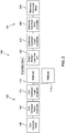
- Figs. 2 and 3 illustrate a non-limiting example of the conveyor cart 102 being aligned with a stationary conveyor 104 that is designated as a loading station (i.e., loading onto the conveyor cart 102).
- the stationary conveyor 104 may be provided with the first stationary sensor 212 and the first stationary reflector 216.
- the conveyor cart logic controller 110 may know that the conveyor cart 102 and the stationary conveyor 104 are aligned and ready to perform a task.
- the stationary conveyor 104 only including the first stationary sensor 212 and the first stationary reflector 216, the second cart sensor 114 may not align with a corresponding reflector and may be blocked (e.g., a beam emitted therefrom may not be aligned with a reflector).
- the condition of having the first cart sensor 112 aligned with a reflector and the second cart sensor 114 blocked may indicate to the conveyor cart logic controller 110 that the conveyor cart 102 has arrived at a loading stationary conveyor 104.
- the conveyor cart logic controller 110 may then instruct the conveyor cart motor controller 108 to rotate the rollers in a first direction to receive a load from the stationary conveyor 104 (i.e., a load may be transferred from the stationary conveyor 104 to the conveyor cart 102).
- the conveyor cart 102 and the stationary controller 104 may be in communication with a system controller (e.g., a warehouse management system).
- a system controller e.g., a warehouse management system
- the system controller may provide instructions to the conveyor cart 102 and the stationary conveyor 104 to move the rollers thereof in a desired direction to transfer a load from the stationary conveyor 104 to the conveyor cart 102.
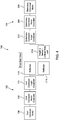
- Figs. 4 and 5 illustrate a non-limiting example of the conveyor cart 102 being aligned with a stationary conveyor 104 that is designated as an unloading station (i.e., unloading onto the stationary conveyor 104).
- the stationary conveyor 104 may be provided with the second stationary sensor 212 and the second stationary reflector 218.
- the conveyor cart logic controller 110 may know that the conveyor cart 102 and the stationary conveyor 104 are aligned and ready to perform a task.
- the first cart sensor 112 may not align with a corresponding reflector and may be blocked.
- the condition of having the second cart sensor 114 aligned with a reflector and the first cart sensor 112 blocked may indicate to the conveyor cart logic controller 110 that the conveyor cart 102 has arrived at an unloading stationary conveyor 104.
- the conveyor cart logic controller 110 may then instruct the conveyor cart motor controller 108 to rotate the rollers in a second direction to unload a load onto the stationary conveyor 104 (i.e., a load may be transferred from the conveyor cart 102 to the stationary conveyor 104).
- the conveyor cart 102 and the stationary controller 104 may be in communication with a system controller (e.g., a warehouse management system).
- a system controller e.g., a warehouse management system
- the system controller may provide instructions to the conveyor cart 102 and the stationary conveyor 104 to move the rollers thereof in a desired direction to transfer a load from the conveyor cart 102 to the conveyor cart 104.
- Fig. 6 illustrates one non-limiting example of the conveyor cart 102 and the stationary conveyor 104.
- the conveyor cart 102 may be attached to a material handling vehicle 300, for example, in the form of a tugger of a tow tractor.
- each of the conveyor cart 102 and the stationary conveyor 104 may include a plurality of rollers that are selectively rotatable via a motor.
- the conveyor cart 102 may include a plurality of conveyor cart rollers 302 that are coupled to the cart conveyor motor 106
- the stationary conveyor 304 may include a plurality of stationary conveyor rollers 304 that are coupled to the stationary conveyor motor 206.
- the stationary conveyor 104 may be supporting a load 308 and the material handling vehicle 200 is moving the conveyor cart 102 into alignment with the stationary conveyor 104.
- the alignment and task indication system 100 may be utilized in this non-limiting application to efficiently determine when the conveyor cart 102 is align with the stationary conveyor 104 and what task is to be performed (e.g., loading onto the conveyor cart 102 or unloading from the conveyor cart 102).
- the conveyor cart 102 may approach the stationary conveyor 104 (see Fig. 6 ) via the attachment to the material handling vehicle 300.
- the system controller e.g., the warehouse management system
- the system controller may monitor the first cart sensor 112, the second cart sensor 114, the first stationary conveyor sensor 212, and the second stationary conveyor sensor 214 to determine, at step 702, when the conveyor cart 102 is aligned with the stationary conveyor 104.
- At least one of the first cart sensor 112 and the second cart sensor 114 may be aligned with a corresponding reflector on the stationary conveyor 104 and at least one of the first stationary sensor 212 and the second stationary sensor 214 may be aligned with a corresponding reflector on the conveyor cart 102.
- at least one sensor on opposing sides of the conveyor cart 102 and the stationary conveyor 104 may be simultaneously aligned to confirm alignment between the conveyor cart 102 and the stationary conveyor 104 at step 704.
- the system controller e.g., the warehouse management system
- the global controller may provide an indication of alignment between the conveyor cart 102 and the stationary conveyor 104 prior to proceeding to task determination. If the conditions to confirm alignment are not met at step 702, the conveyor cart 102 may continue to approach the stationary conveyor 104.
- the system controller e.g., the warehouse management system or another global controller that is wirelessly in communication with both of the cart conveyor logic controller 110 and the stationary conveyor logic controller 210 may determine the task to be performed at step 706 by monitoring the status of each of the first cart sensor 112, the second cart sensor 114, the first stationary conveyor sensor 212, and the second stationary conveyor sensor 214.
- the first cart sensor 112 which is arranged at a first height, may be aligned with a reflector (e.g., the first stationary reflector 216) and the second cart sensor 114, which is arranged at a second height, may be blocked (i.e., not aligned with a reflector).
- the conveyor logic controller 110 may be configured to determine that the stationary conveyor 104, which the conveyor cart 102 is aligned with, is a loading station where a pallet or load is present on the stationary conveyor 104. In this scenario, the conveyor logic controller 110 may be configured to instruct the cart conveyor motor controller 108 to rotate the conveyor cart rollers 302, via the cart conveyor motor 106, to receive a load onto the conveyor cart 102 at step 710.
- the first stationary sensor 212 which is arranged at a first height, may be aligned with a reflector (e.g., the first cart reflector 116) and the second stationary sensor 214, which is arranged at a second height, may be blocked (i.e., not aligned with a reflector).
- the stationary logic controller 210 may be configured to determine that the conveyor cart 102, which the stationary conveyor 104 is aligned with, is empty and is ready to receive a pallet or load that present on the stationary conveyor 104.
- the stationary logic controller 210 may be configured to instruct the stationary conveyor motor controller 208 to rotate the stationary conveyor rollers 304, via the stationary conveyor motor 206, to unload a load onto the conveyor cart 102 at step 710.
- the first cart sensor 112 which is arranged at a first height, may be blocked (i.e., not aligned with a reflector) and the second cart sensor 114, which is arranged at a second height, may be aligned with a reflector (e.g., the second stationary reflector 218).
- the conveyor logic controller 110 may be configured to determine that the stationary conveyor 104, which the conveyor cart 102 is aligned with, is an unloading station where a pallet or load is present on the conveyor cart 102 and the stationary conveyor 104 is empty.
- the conveyor logic controller 110 may be configured to instruct the cart conveyor motor controller 108 to rotate the conveyor cart rollers 302, via the cart conveyor motor 106, to transfer a load from the conveyor cart 102 to the stationary conveyor 104 at step 714.
- the first stationary sensor 212 which is arranged at a first height, may be blocked (i.e., not aligned with a reflector) and the second stationary sensor 114, which is arranged at a second height, may be aligned with a reflector (e.g., the second cart reflector 118).
- the conveyor logic controller 110 may be configured to determine that the conveyor cart 102, which the stationary conveyor 104 is aligned with, is supporting a pallet or load to be unloaded onto the stationary conveyor 104.
- the conveyor logic controller 110 may be configured to instruct the stationary conveyor motor controller 208 to rotate the stationary conveyor rollers 304, via the stationary conveyor motor 206, to receive a load from the conveyor cart 102 at step 714.
- the rotation of the conveyor cart rollers 302 and the stationary conveyor roller 304 may be rotated substantially simultaneously to ensure that the load is transferred either from the conveyor cart 102 to the stationary conveyor 104 or from the stationary conveyor 104 to the conveyor cart 102.
- the system and methods described herein enable the efficient determination of the alignment between a stationary conveyor and a movable conveyor, in addition to the task to be performed when the conveyors are aligned. For example, by determining the task to be performed (e.g., loading onto the movable conveyor or unloading from the movable conveyor) via the blocking and alignment of sensors at different heights, the decision making process for how to operate the conveyors may become more computationally efficient. In addition, the alignment and task determination may aid in making the loading and unloading process between the conveyors autonomous.
Landscapes
- Engineering & Computer Science (AREA)
- Mechanical Engineering (AREA)
- Warehouses Or Storage Devices (AREA)
- Control Of Conveyors (AREA)
- Intermediate Stations On Conveyors (AREA)
Applications Claiming Priority (1)
| Application Number | Priority Date | Filing Date | Title |
|---|---|---|---|
| US201962830314P | 2019-04-05 | 2019-04-05 |
Publications (3)
| Publication Number | Publication Date |
|---|---|
| EP3718935A1 true EP3718935A1 (de) | 2020-10-07 |
| EP3718935B1 EP3718935B1 (de) | 2025-09-10 |
| EP3718935C0 EP3718935C0 (de) | 2025-09-10 |
Family
ID=70110193
Family Applications (1)
| Application Number | Title | Priority Date | Filing Date |
|---|---|---|---|
| EP20167284.7A Active EP3718935B1 (de) | 2019-04-05 | 2020-03-31 | Systeme und verfahren zum ausrichten von förderwagen |
Country Status (5)
| Country | Link |
|---|---|
| US (2) | US11235931B2 (de) |
| EP (1) | EP3718935B1 (de) |
| CN (2) | CN116620768B (de) |
| AU (2) | AU2020202272B2 (de) |
| CA (1) | CA3077871A1 (de) |
Families Citing this family (4)
| Publication number | Priority date | Publication date | Assignee | Title |
|---|---|---|---|---|
| DE102017122704A1 (de) * | 2017-09-29 | 2019-04-04 | Lr Intralogistik Gmbh | Vorrichtung zur Lastübergabe |
| US11905125B1 (en) * | 2020-03-26 | 2024-02-20 | Material Handling Systems, Inc. | Parcel cart loading system |
| TWI783811B (zh) * | 2021-12-03 | 2022-11-11 | 王賢明 | 具輔助運輸滑軌之運輸裝置 |
| US20250058984A1 (en) * | 2023-08-17 | 2025-02-20 | Ford Global Technologies, Llc | Systems and methods for loading and unloading bins containing items |
Citations (5)
| Publication number | Priority date | Publication date | Assignee | Title |
|---|---|---|---|---|
| US3815084A (en) * | 1971-11-19 | 1974-06-04 | Eaton Corp | Retroreflective addressing technique |
| EP0035890A1 (de) * | 1980-03-07 | 1981-09-16 | Lear Siegler, Inc. | Vorrichtung und Verfahren zur Relativlagesteuerung zweier Gegenstände, wie z.B. eines Gütertransportfahrzeuges und eines Lagerplatzes |
| US4944357A (en) * | 1989-04-27 | 1990-07-31 | Caterpillar Industrial Inc. | Power transferring arrangement |
| US5664929A (en) * | 1992-10-01 | 1997-09-09 | Daifuku Co., Ltd. | Article transportation system |
| US20180169944A1 (en) * | 2016-12-19 | 2018-06-21 | CL SCHUTZRECHTSVERWALTUNGS GMBH Lichtenfels | System for additive production of three-dimensional objects |
Family Cites Families (22)
| Publication number | Priority date | Publication date | Assignee | Title |
|---|---|---|---|---|
| JPS5922825A (ja) | 1982-07-28 | 1984-02-06 | Toshiba Corp | 搬送移載装置 |
| US4792995A (en) * | 1987-08-19 | 1988-12-20 | Caterpillar Industrial Inc. | Bidirectional roller deck control for a self guided vehicle |
| EP0335196A1 (de) * | 1988-03-31 | 1989-10-04 | Caterpillar Industrial Inc. | Vorrichtung und Verfahren zum Steuern der Position eines Hubmastes |
| US5202832A (en) * | 1991-01-29 | 1993-04-13 | R. R. Donnelley & Sons Co. | Material handling automation system using portable transfer module |
| US7695235B1 (en) * | 2002-07-19 | 2010-04-13 | Rallis John H | Automated warehousing and cargo loading system |
| KR100581623B1 (ko) * | 2004-01-15 | 2006-05-23 | 오티스 엘리베이터 컴파니 | 리프트와 대차 사이의 단차에 의한 팔레트 이송 불능문제를 해결하기 위한 주차장치 및 팔레트 이송 제어방법 |
| CN101367473B (zh) * | 2007-08-16 | 2010-12-08 | 中国国际海运集装箱(集团)股份有限公司 | 货物转运与输送系统 |
| US7588139B1 (en) * | 2008-08-12 | 2009-09-15 | Campbell Iii William Arthur | Conveyor assembly |
| EP3410248B1 (de) * | 2008-12-04 | 2021-05-05 | Crown Equipment Corporation | Mehrzonenerfassung für fahrzeugen zur handhabung von materialien |
| DE102009027245A1 (de) * | 2009-06-26 | 2010-12-30 | Deere & Company, Moline | Steueranordnung zur Kontrolle des Überladens landwirtschaftlichen Ernteguts von einer Erntemaschine auf ein Transportfahrzeug |
| KR20110015129A (ko) * | 2009-08-07 | 2011-02-15 | (주)범창종합기술 | 컨테이너의 로딩/언로딩이 가능한 2중 모드 트레일러 |
| US9861040B2 (en) * | 2012-02-10 | 2018-01-09 | Deere & Company | Method and stereo vision system for facilitating the unloading of agricultural material from a vehicle |
| CN103010655B (zh) * | 2012-12-28 | 2016-01-27 | 上海凯思尔电子有限公司 | 全自动收板机的输送系统 |
| CN103213800B (zh) * | 2013-05-07 | 2015-04-01 | 中国人民解放军军事交通学院 | 自动化立体仓库单元货物自动调正入库站台及其调正方法 |
| CN103434674B (zh) * | 2013-09-09 | 2015-06-17 | 昆明烟机集团三机有限公司 | 包装机辅料自动装载系统 |
| DE102014116725A1 (de) * | 2014-11-14 | 2016-05-19 | Haver & Boecker Ohg | Verfahren zum Beladen von Ladeflächen und Beladeeinrichtung |
| BR112017010013A2 (pt) * | 2014-11-19 | 2018-01-02 | Agco Corp | sistema de controle de oscilação de transportador de descarregamento |
| US10048697B1 (en) * | 2015-10-29 | 2018-08-14 | Vecna Technologies, Inc. | Mobile robot with conveyor system |
| KR101725406B1 (ko) * | 2016-03-31 | 2017-04-11 | 로체 시스템즈(주) | 이송 로봇의 오토 티칭 시스템 |
| US10793369B2 (en) * | 2017-07-12 | 2020-10-06 | A9.Com, Inc. | Conveyor system for autonomous robot |
| DE112018004765T5 (de) * | 2017-08-25 | 2020-06-04 | Jonathan Sutter | Zusammenstellung eines Wagenförderers |
| CN107804664A (zh) * | 2017-09-19 | 2018-03-16 | 浙江工贸职业技术学院 | 电子商务供应链轨道拼接式物流车 |
-
2020
- 2020-03-30 US US16/834,630 patent/US11235931B2/en active Active
- 2020-03-31 AU AU2020202272A patent/AU2020202272B2/en active Active
- 2020-03-31 EP EP20167284.7A patent/EP3718935B1/de active Active
- 2020-04-03 CA CA3077871A patent/CA3077871A1/en active Pending
- 2020-04-07 CN CN202310783753.3A patent/CN116620768B/zh active Active
- 2020-04-07 CN CN202010265304.6A patent/CN111792250B/zh active Active
-
2022
- 2022-01-27 US US17/586,569 patent/US11807459B2/en active Active
-
2025
- 2025-09-19 AU AU2025234228A patent/AU2025234228A1/en active Pending
Patent Citations (5)
| Publication number | Priority date | Publication date | Assignee | Title |
|---|---|---|---|---|
| US3815084A (en) * | 1971-11-19 | 1974-06-04 | Eaton Corp | Retroreflective addressing technique |
| EP0035890A1 (de) * | 1980-03-07 | 1981-09-16 | Lear Siegler, Inc. | Vorrichtung und Verfahren zur Relativlagesteuerung zweier Gegenstände, wie z.B. eines Gütertransportfahrzeuges und eines Lagerplatzes |
| US4944357A (en) * | 1989-04-27 | 1990-07-31 | Caterpillar Industrial Inc. | Power transferring arrangement |
| US5664929A (en) * | 1992-10-01 | 1997-09-09 | Daifuku Co., Ltd. | Article transportation system |
| US20180169944A1 (en) * | 2016-12-19 | 2018-06-21 | CL SCHUTZRECHTSVERWALTUNGS GMBH Lichtenfels | System for additive production of three-dimensional objects |
Also Published As
| Publication number | Publication date |
|---|---|
| AU2025234228A1 (en) | 2025-10-09 |
| EP3718935B1 (de) | 2025-09-10 |
| CN116620768A (zh) | 2023-08-22 |
| AU2020202272A1 (en) | 2020-10-22 |
| CA3077871A1 (en) | 2020-10-05 |
| US20220144548A1 (en) | 2022-05-12 |
| EP3718935C0 (de) | 2025-09-10 |
| US11807459B2 (en) | 2023-11-07 |
| US20200317448A1 (en) | 2020-10-08 |
| CN111792250B (zh) | 2023-07-07 |
| US11235931B2 (en) | 2022-02-01 |
| AU2020202272B2 (en) | 2025-06-26 |
| CN116620768B (zh) | 2026-02-17 |
| CN111792250A (zh) | 2020-10-20 |
Similar Documents
| Publication | Publication Date | Title |
|---|---|---|
| US11807459B2 (en) | Conveyor cart alignment systems and methods | |
| EP3268827B1 (de) | Automatisiertes geführtes fahrzeugsystem | |
| US9890025B2 (en) | Mechanical tipping assembly for mobile drive unit of inventory system | |
| EP3234720B1 (de) | Konfigurierbare mobile fördererkomponente | |
| CN111017453B (zh) | 用于货物的装载和卸载的装置 | |
| WO2020086242A1 (en) | Autonomous ground vehicle (agv) cart for item distribution | |
| EP3953276B1 (de) | Verwaltungssystem für logistikeinrichtungen | |
| KR20160057668A (ko) | 지능형 무인 이/적재 시스템 및 이를 이용한 이/적재 방법 | |
| US20240002163A1 (en) | Interoperable robotic system to load/unload trucks and other containers | |
| WO2018225635A1 (ja) | 台車制御システム | |
| CN214376001U (zh) | 散装料处理系统 | |
| HK40038682A (en) | Conveyor cart alignment systems and methods | |
| HK40038682B (en) | Conveyor cart alignment systems and methods | |
| HK40093847A (en) | Conveyor cart alignment systems and methods | |
| WO2018225634A1 (ja) | 台車ロボット | |
| JP5516972B2 (ja) | 物品搬送設備 | |
| KR101795855B1 (ko) | 회전형 운송물 중계 장치 및 이를 이용한 선적 방법 | |
| CN108455151A (zh) | 基于牵引式agv的装配式建筑仓储系统及方法 | |
| US20250100856A1 (en) | Autonomous robot with pallet loading capability | |
| HK40051646A (en) | Material handling vehicle behavior modification based on task classification |
Legal Events
| Date | Code | Title | Description |
|---|---|---|---|
| PUAI | Public reference made under article 153(3) epc to a published international application that has entered the european phase |
Free format text: ORIGINAL CODE: 0009012 |
|
| STAA | Information on the status of an ep patent application or granted ep patent |
Free format text: STATUS: THE APPLICATION HAS BEEN PUBLISHED |
|
| AK | Designated contracting states |
Kind code of ref document: A1 Designated state(s): AL AT BE BG CH CY CZ DE DK EE ES FI FR GB GR HR HU IE IS IT LI LT LU LV MC MK MT NL NO PL PT RO RS SE SI SK SM TR |
|
| AX | Request for extension of the european patent |
Extension state: BA ME |
|
| STAA | Information on the status of an ep patent application or granted ep patent |
Free format text: STATUS: REQUEST FOR EXAMINATION WAS MADE |
|
| 17P | Request for examination filed |
Effective date: 20210331 |
|
| RBV | Designated contracting states (corrected) |
Designated state(s): AL AT BE BG CH CY CZ DE DK EE ES FI FR GB GR HR HU IE IS IT LI LT LU LV MC MK MT NL NO PL PT RO RS SE SI SK SM TR |
|
| STAA | Information on the status of an ep patent application or granted ep patent |
Free format text: STATUS: EXAMINATION IS IN PROGRESS |
|
| 17Q | First examination report despatched |
Effective date: 20230207 |
|
| GRAP | Despatch of communication of intention to grant a patent |
Free format text: ORIGINAL CODE: EPIDOSNIGR1 |
|
| STAA | Information on the status of an ep patent application or granted ep patent |
Free format text: STATUS: GRANT OF PATENT IS INTENDED |
|
| INTG | Intention to grant announced |
Effective date: 20241122 |
|
| GRAJ | Information related to disapproval of communication of intention to grant by the applicant or resumption of examination proceedings by the epo deleted |
Free format text: ORIGINAL CODE: EPIDOSDIGR1 |
|
| STAA | Information on the status of an ep patent application or granted ep patent |
Free format text: STATUS: EXAMINATION IS IN PROGRESS |
|
| GRAP | Despatch of communication of intention to grant a patent |
Free format text: ORIGINAL CODE: EPIDOSNIGR1 |
|
| STAA | Information on the status of an ep patent application or granted ep patent |
Free format text: STATUS: GRANT OF PATENT IS INTENDED |
|
| INTC | Intention to grant announced (deleted) | ||
| INTG | Intention to grant announced |
Effective date: 20250404 |
|
| GRAS | Grant fee paid |
Free format text: ORIGINAL CODE: EPIDOSNIGR3 |
|
| GRAA | (expected) grant |
Free format text: ORIGINAL CODE: 0009210 |
|
| STAA | Information on the status of an ep patent application or granted ep patent |
Free format text: STATUS: THE PATENT HAS BEEN GRANTED |
|
| AK | Designated contracting states |
Kind code of ref document: B1 Designated state(s): AL AT BE BG CH CY CZ DE DK EE ES FI FR GB GR HR HU IE IS IT LI LT LU LV MC MK MT NL NO PL PT RO RS SE SI SK SM TR |
|
| REG | Reference to a national code |
Ref country code: GB Ref legal event code: FG4D |
|
| REG | Reference to a national code |
Ref country code: CH Ref legal event code: EP |
|
| REG | Reference to a national code |
Ref country code: DE Ref legal event code: R096 Ref document number: 602020058382 Country of ref document: DE |
|
| REG | Reference to a national code |
Ref country code: IE Ref legal event code: FG4D |
|
| U01 | Request for unitary effect filed |
Effective date: 20251010 |
|
| U07 | Unitary effect registered |
Designated state(s): AT BE BG DE DK EE FI FR IT LT LU LV MT NL PT RO SE SI Effective date: 20251017 |
|
| PG25 | Lapsed in a contracting state [announced via postgrant information from national office to epo] |
Ref country code: NO Free format text: LAPSE BECAUSE OF FAILURE TO SUBMIT A TRANSLATION OF THE DESCRIPTION OR TO PAY THE FEE WITHIN THE PRESCRIBED TIME-LIMIT Effective date: 20251210 |
|
| PG25 | Lapsed in a contracting state [announced via postgrant information from national office to epo] |
Ref country code: HR Free format text: LAPSE BECAUSE OF FAILURE TO SUBMIT A TRANSLATION OF THE DESCRIPTION OR TO PAY THE FEE WITHIN THE PRESCRIBED TIME-LIMIT Effective date: 20250910 |
|
| PG25 | Lapsed in a contracting state [announced via postgrant information from national office to epo] |
Ref country code: GR Free format text: LAPSE BECAUSE OF FAILURE TO SUBMIT A TRANSLATION OF THE DESCRIPTION OR TO PAY THE FEE WITHIN THE PRESCRIBED TIME-LIMIT Effective date: 20251211 |
|
| PG25 | Lapsed in a contracting state [announced via postgrant information from national office to epo] |
Ref country code: PL Free format text: LAPSE BECAUSE OF FAILURE TO SUBMIT A TRANSLATION OF THE DESCRIPTION OR TO PAY THE FEE WITHIN THE PRESCRIBED TIME-LIMIT Effective date: 20250910 |
|
| PG25 | Lapsed in a contracting state [announced via postgrant information from national office to epo] |
Ref country code: RS Free format text: LAPSE BECAUSE OF FAILURE TO SUBMIT A TRANSLATION OF THE DESCRIPTION OR TO PAY THE FEE WITHIN THE PRESCRIBED TIME-LIMIT Effective date: 20251210 |
|
| PG25 | Lapsed in a contracting state [announced via postgrant information from national office to epo] |
Ref country code: ES Free format text: LAPSE BECAUSE OF FAILURE TO SUBMIT A TRANSLATION OF THE DESCRIPTION OR TO PAY THE FEE WITHIN THE PRESCRIBED TIME-LIMIT Effective date: 20250910 |
|
| U20 | Renewal fee for the european patent with unitary effect paid |
Year of fee payment: 7 Effective date: 20260209 |
|
| PG25 | Lapsed in a contracting state [announced via postgrant information from national office to epo] |
Ref country code: SM Free format text: LAPSE BECAUSE OF FAILURE TO SUBMIT A TRANSLATION OF THE DESCRIPTION OR TO PAY THE FEE WITHIN THE PRESCRIBED TIME-LIMIT Effective date: 20250910 |
|
| PGFP | Annual fee paid to national office [announced via postgrant information from national office to epo] |
Ref country code: GB Payment date: 20260209 Year of fee payment: 7 |
|
| PG25 | Lapsed in a contracting state [announced via postgrant information from national office to epo] |
Ref country code: IS Free format text: LAPSE BECAUSE OF FAILURE TO SUBMIT A TRANSLATION OF THE DESCRIPTION OR TO PAY THE FEE WITHIN THE PRESCRIBED TIME-LIMIT Effective date: 20260110 |
|
| PG25 | Lapsed in a contracting state [announced via postgrant information from national office to epo] |
Ref country code: CZ Free format text: LAPSE BECAUSE OF FAILURE TO SUBMIT A TRANSLATION OF THE DESCRIPTION OR TO PAY THE FEE WITHIN THE PRESCRIBED TIME-LIMIT Effective date: 20250910 |
|
| PG25 | Lapsed in a contracting state [announced via postgrant information from national office to epo] |
Ref country code: SK Free format text: LAPSE BECAUSE OF FAILURE TO SUBMIT A TRANSLATION OF THE DESCRIPTION OR TO PAY THE FEE WITHIN THE PRESCRIBED TIME-LIMIT Effective date: 20250910 |
|
| PLBE | No opposition filed within time limit |
Free format text: ORIGINAL CODE: 0009261 |
|
| STAA | Information on the status of an ep patent application or granted ep patent |
Free format text: STATUS: NO OPPOSITION FILED WITHIN TIME LIMIT |
|
| REG | Reference to a national code |
Ref country code: CH Ref legal event code: L10 Free format text: ST27 STATUS EVENT CODE: U-0-0-L10-L00 (AS PROVIDED BY THE NATIONAL OFFICE) Effective date: 20260722 |