EP3719202A1 - Machine de traitement du sol - Google Patents
Machine de traitement du sol Download PDFInfo
- Publication number
- EP3719202A1 EP3719202A1 EP20161354.4A EP20161354A EP3719202A1 EP 3719202 A1 EP3719202 A1 EP 3719202A1 EP 20161354 A EP20161354 A EP 20161354A EP 3719202 A1 EP3719202 A1 EP 3719202A1
- Authority
- EP
- European Patent Office
- Prior art keywords
- milling drum
- milling
- machine
- speed
- kinetic mass
- Prior art date
- Legal status (The legal status is an assumption and is not a legal conclusion. Google has not performed a legal analysis and makes no representation as to the accuracy of the status listed.)
- Granted
Links
Images


Classifications
-
- E—FIXED CONSTRUCTIONS
- E01—CONSTRUCTION OF ROADS, RAILWAYS, OR BRIDGES
- E01C—CONSTRUCTION OF, OR SURFACES FOR, ROADS, SPORTS GROUNDS, OR THE LIKE; MACHINES OR AUXILIARY TOOLS FOR CONSTRUCTION OR REPAIR
- E01C19/00—Machines, tools or auxiliary devices for preparing or distributing paving materials, for working the placed materials, or for forming, consolidating, or finishing the paving
- E01C19/22—Machines, tools or auxiliary devices for preparing or distributing paving materials, for working the placed materials, or for forming, consolidating, or finishing the paving for consolidating or finishing laid-down unset materials
- E01C19/23—Rollers therefor; Such rollers usable also for compacting soil
- E01C19/28—Vibrated rollers or rollers subjected to impacts, e.g. hammering blows
- E01C19/286—Vibration or impact-imparting means; Arrangement, mounting or adjustment thereof; Construction or mounting of the rolling elements, transmission or drive thereto, e.g. to vibrator mounted inside the roll
-
- E—FIXED CONSTRUCTIONS
- E01—CONSTRUCTION OF ROADS, RAILWAYS, OR BRIDGES
- E01C—CONSTRUCTION OF, OR SURFACES FOR, ROADS, SPORTS GROUNDS, OR THE LIKE; MACHINES OR AUXILIARY TOOLS FOR CONSTRUCTION OR REPAIR
- E01C23/00—Auxiliary devices or arrangements for constructing, repairing, reconditioning, or taking-up road or like surfaces
- E01C23/06—Devices or arrangements for working the finished surface; Devices for repairing or reconditioning the surface of damaged paving; Recycling in place or on the road
- E01C23/08—Devices or arrangements for working the finished surface; Devices for repairing or reconditioning the surface of damaged paving; Recycling in place or on the road for roughening or patterning; for removing the surface down to a predetermined depth high spots or material bonded to the surface, e.g. markings; for maintaining earth roads, clay courts or like surfaces by means of surface working tools, e.g. scarifiers, levelling blades
- E01C23/085—Devices or arrangements for working the finished surface; Devices for repairing or reconditioning the surface of damaged paving; Recycling in place or on the road for roughening or patterning; for removing the surface down to a predetermined depth high spots or material bonded to the surface, e.g. markings; for maintaining earth roads, clay courts or like surfaces by means of surface working tools, e.g. scarifiers, levelling blades using power-driven tools, e.g. vibratory tools
- E01C23/088—Rotary tools, e.g. milling drums
-
- E—FIXED CONSTRUCTIONS
- E01—CONSTRUCTION OF ROADS, RAILWAYS, OR BRIDGES
- E01C—CONSTRUCTION OF, OR SURFACES FOR, ROADS, SPORTS GROUNDS, OR THE LIKE; MACHINES OR AUXILIARY TOOLS FOR CONSTRUCTION OR REPAIR
- E01C19/00—Machines, tools or auxiliary devices for preparing or distributing paving materials, for working the placed materials, or for forming, consolidating, or finishing the paving
- E01C19/22—Machines, tools or auxiliary devices for preparing or distributing paving materials, for working the placed materials, or for forming, consolidating, or finishing the paving for consolidating or finishing laid-down unset materials
- E01C19/23—Rollers therefor; Such rollers usable also for compacting soil
- E01C19/236—Construction of the rolling elements, e.g. surface configuration, rolling surface formed by endless track
-
- E—FIXED CONSTRUCTIONS
- E01—CONSTRUCTION OF ROADS, RAILWAYS, OR BRIDGES
- E01C—CONSTRUCTION OF, OR SURFACES FOR, ROADS, SPORTS GROUNDS, OR THE LIKE; MACHINES OR AUXILIARY TOOLS FOR CONSTRUCTION OR REPAIR
- E01C19/00—Machines, tools or auxiliary devices for preparing or distributing paving materials, for working the placed materials, or for forming, consolidating, or finishing the paving
- E01C19/22—Machines, tools or auxiliary devices for preparing or distributing paving materials, for working the placed materials, or for forming, consolidating, or finishing the paving for consolidating or finishing laid-down unset materials
- E01C19/23—Rollers therefor; Such rollers usable also for compacting soil
- E01C19/26—Rollers therefor; Such rollers usable also for compacting soil self-propelled or fitted to road vehicles
- E01C19/266—Rollers therefor; Such rollers usable also for compacting soil self-propelled or fitted to road vehicles fitted to vehicles, road-construction or earth-moving machinery, e.g. auxiliary roll readily movable to operative position ; provided with means for facilitating transport; Means for transporting rollers; Arrangements or attachments for converting vehicles into rollers, e.g. rolling sleeves for wheels
-
- E—FIXED CONSTRUCTIONS
- E01—CONSTRUCTION OF ROADS, RAILWAYS, OR BRIDGES
- E01C—CONSTRUCTION OF, OR SURFACES FOR, ROADS, SPORTS GROUNDS, OR THE LIKE; MACHINES OR AUXILIARY TOOLS FOR CONSTRUCTION OR REPAIR
- E01C2301/00—Machine characteristics, parts or accessories not otherwise provided for
- E01C2301/30—Cabin details
Definitions
- the invention relates to a soil cultivation machine, in particular a road milling machine, a stabilizer or the like, with a milling drum which is rotatably mounted on a machine frame and which is equipped or can be equipped with working tools on its outer circumference, the working tools being provided to be in contact during operation to step with the soil to be processed in order to remove it, a drive unit being provided which drives the milling drum by means of a drive motor, a drive shaft connected to the milling drum that can be coupled to the drive motor, and with a load element as a kinetic mass to increase the kinetic energy of the milling drum is provided.
- Soil cultivation machines are known in various designs.
- the DE 20 122 928 U1 a road milling machine as a soil tillage machine. It has a drive train. This comprises a drive motor, a clutch and a gear (the so-called milling drum gear), as well as organs that mediate these units, in particular shafts, toothed or endless drives.
- working tools are understood to mean, in particular, structural units of the milling drum that functionally interact with the milled material during the work process.
- these are the milling chisels with which the The subsurface is milled and / or ejector tools, which have a guiding and conveying function for the milled material.
- the work result is significantly influenced by the speed of the milling drum.
- the optimal speed generally depends on the application.
- fine milling road surfaces to restore grip with a shallow milling depth, relatively higher speeds are required in order to generate a uniform milling pattern. Therefore, only a superficial treatment takes place here.
- a high weight of the tillage machine helps to increase the smoothness even at low speeds. This is, however, disadvantageous in several respects, as it places special demands on the transport (large milling machines> 40 t; heavy transport) on the one hand and restricts the possibilities of use on statically less stable surfaces on the other.
- a road milling machine in which a milling drum can be driven via a drive train.
- the drive train includes, in particular, a drive motor, a clutch and a transmission (the so-called milling drum transmission).
- the DE 10 2014 118 802 A1 now suggests on Drive train or on the milling drum as a kinetic mass to attach a load weight to increase the kinetic energy exchangeably.
- the milling drum has, for example, pocket-shaped receptacles into which load weights can be inserted.
- This road milling machine makes use of the knowledge that smoother running of the milling drum can be achieved if the kinetic energy in the drive train and / or the milling drum is increased.
- m indicates the amount of the rotating mass and r the distance of this mass from the axis of rotation.
- the product mr 2 represents the so-called moment of inertia of the moving mass and ⁇ the angular velocity (2 ⁇ * speed).
- the milling drum can be individually adapted to the task at hand. However, a certain set-up effort is required here for adaptation.
- the weights put a load on the drive motor and the coupling or the milling gear, especially when the machine starts up.
- the object of the invention is to provide a soil cultivating machine of the type mentioned at the outset, which can be easily adapted to different milling applications and is characterized by a high degree of smoothness and, at the same time, low stress on the drive train.
- the kinetic mass can be coupled or decoupled via a switchable coupling to the rotatable milling drum or to a rotating body that is directly or indirectly coupled to the milling drum.
- the kinetic mass can either be coupled to or uncoupled from the milling drum via the switchable coupling, as desired by the machine operator.
- the soil tillage implement is optimized for standard operation. If a change from this standard mode to lower speeds is to be made, the machine operator can conveniently switch on the kinetic mass via the switchable clutch in order to adapt the machine. Complex setup processes for adapting the machine can be avoided.
- the kinetic mass is only coupled to the drive shaft or the bearing shaft when the milling drum is already in rotating operation. In this way, the milling drum can be started up without the kinetic mass being switched on. Accordingly, the kinetic mass then does not load the drive train with its own weight, in particular the drive motor, the gearbox or a shift clutch that mediates the drive motor and the gearbox. This simple measure extends the service life of the components of the drive train.
- the speed can be reduced during operation with a simultaneous increase in the moment of inertia.
- the required power consumption is reduced, which in turn leads to a reduction in fuel consumption and emissions from the drive motor leads.
- With lower speeds there is also less bit wear and a lower coolant requirement.
- the drive shaft or a bearing shaft arranged opposite the drive shaft, by means of which the milling drum is mounted on a machine frame forms the body of rotation.
- the kinetic mass to the drive shaft or the bearing shaft, there is a lower structural design Effort required. In particular, there is usually sufficient space available at these points Available that enables the integration of the kinetic mass and the switchable clutch.
- the kinetic mass is exchangeable. It can then in particular be exchanged for another kinetic mass with a different weight. This makes it possible to adapt the milling drum to any application situation. However, it is usually sufficient if a suitable kinetic mass is available that is suitably dimensioned to cover a wide range of applications.
- the kinetic mass is coupled to the rotary body or the milling drum by means of a transmission gear, and that the transmission gear changes the speed at which the milling drum or the rotary body rotates to a higher speed at which the kinetic mass rotates, translated.
- the transmission gear is designed as a switchable transmission with two or more transmission stages or as a transmission in which the transmission ratio is continuously variable. In this way, the speed can be varied in different stages (or continuously). This makes it possible to change the speed at which the kinetic mass rotates in order to change the moment of inertia acting on the milling drum and thus to be able to make a further adjustment to individual work requirements.
- the bearing shaft or the drive shaft of the milling drum is guided directly to the drive side of the transmission gear. This means that there is minimal construction effort.
- the bearing shaft or the drive shaft is guided indirectly to the drive side of the transmission gear with the intermediation of at least one rotating body.
- a variant of the invention is particularly preferred such that the output side of the transmission gear is connected to the kinetic mass via the clutch. At this point, the kinetic mass can easily be coupled or uncoupled with little structural effort.
- the rotating parts of the transmission gear also contribute to a certain extent to increasing the kinetic energy and stabilizing the milling operation, even when the kinetic mass is decoupled.
- the switchable coupling is arranged between the bearing shaft and the input side of the transmission gear.
- both the transmission gear and the kinetic mass can be decoupled at the same time.
- the transmission gear In the uncoupled state, the transmission gear is not operated, which is a measure to optimize wear.
- the invention can particularly preferably provide that the milling drum rotates at a speed in the range between 30 to 240 revolutions / min and the kinetic mass with a speed in the range between 60 to 4000 revolutions / min.
- the speed of the kinetic mass is particularly preferably selected in the range between 1000 and 4000 revolutions / min. This preferred area is particularly suitable for use in road milling machines, since a very smooth running can be achieved here with a relatively low kinetic mass.
- the dimensioning is advantageously carried out in such a way that the moment of inertia of the milling drum has a first value when the clutch is disengaged and that the moment of inertia of the milling drum when the clutch is engaged and the kinetic mass-absorbing assembly has a second value, the second value being at least twice as large as the first value.
- a reliable compensation of imbalances in road milling applications can be achieved if it is provided that the moment of inertia of the kinetic mass is greater than or equal to T / i 2 , where T corresponds to the moment of inertia of the milling drum and i the speed ratio of the speed of the kinetic mass to the speed of the Milling drum is. It is immediately evident that a higher rotational speed can generate a greater effective moment of inertia on the drive side, since this is entered in the square.
- the moment of inertia acting on the milling drum corresponds to the moment of inertia of the milling drum (as well as existing attachments such as parts of the drive train) plus the moment of inertia of the kinetic mass multiplied by the square of the speed ratio i.
- an ideal transmission is assumed here.
- a soil cultivating machine can be characterized in that the transmission gear is arranged at least in some areas in the installation space enclosed by the milling drum. In this way, the transmission gear is housed in a space-saving manner. In addition or as an alternative, it is also conceivable that the transmission gear is accommodated at least in some areas within a milling drum box. Such a construction is recommended if there is already sufficient installation space available in the area of the milling drum box, which enables the integration of the transmission gear. Of course, the transmission gear can also at least regionally be arranged within the milling drum box, at the same time it also protrudes at least in areas into the construction space surrounded by the milling drum.
- the part of the transmission gear that is located in the milling drum box should then be protected from attack by the material removed from the milling drum box by suitable measures. If it is the case that the transmission gear protrudes at least partially into the installation space surrounded by the milling drum, then the milling drum geometry protects the transmission gear
- the milling drum is at least partially accommodated inside the milling drum box, with the bearing shaft being arranged in the area of a side wall of the milling drum box, and that the transmission gear on the milling drum box is outside the interior space accommodating the milling drum, preferably on the outside of the Milling roller box, particularly preferably on the outside of the side wall, attached or arranged.
- Such a procedure is recommended when a sufficiently large space for the transmission gear has to be made available on the side of the milling drum box. Because the transmission gear is arranged outside the milling drum box, it then of course no longer has to be protected from the excavated material.
- the use of a transmission gear can be provided.
- the invention is not restricted to this. Rather, it is also conceivable that the milling drum is coupled to the kinetic mass in the engaged state of the clutch in such a way that the speed of the milling drum corresponds to the speed at which the kinetic mass rotates, neglecting the slip of the clutch.
- a particularly space-saving design can be achieved if it is provided that the coupling and the kinetic mass are arranged within the installation space enclosed by the milling drum.
- a braking device can also be used which is designed to brake the kinetic mass when the clutch is in the open state, that is to say the kinetic mass is then decoupled from the milling drum. This prevents the kinetic mass from being moved as a result of drag torques within the clutch (for example in the case of viscous clutches).
- the coupling can be arranged in the area between the transmission gear and the kinetic mass. This has the advantage that a more cost-effective, weaker clutch can be used.
- the clutch is arranged in front of the transmission gear. Accordingly, when the clutch is disengaged, both the transmission gear and the kinetic mass are decoupled from the milling drum. Since the transmission gear no longer has to be moved in this operating state, there is a better degree of efficiency.
- a monitoring device can also be provided which uses a detection unit to detect one or more machine states.
- a vibration sensor and / or a torque sensor which detects a torque in the area of the drive train, in particular on the drive motor, can be provided.
- the monitoring signal detected by the detection unit is fed to the monitoring device.
- the monitoring signal is evaluated there. If there is an impermissible deviation from a default signal, a switching signal is generated by the monitoring device. This causes the switchable clutch to open using an adjusting element, for example an actuator. If an undesired machine condition occurs, the kinetic mass is then decoupled from the milling drum by actuating the switchable clutch.
- Figure 1 shows a road milling machine 10 as a soil cultivating machine for milling road surfaces made of asphalt, concrete or the like.
- the road milling machine 10 has a machine frame 11 with an operator's platform 12. On the operator's platform 12, the machine operator can operate the road milling machine and control the functions of the road milling machine.
- the machine frame 11 is carried by a chassis 13.
- the chassis 13 comprises, for example, four crawler tracks 14 which are arranged on the front and rear on both sides of the machine frame 11.
- the chain drives 14 allow the road milling machine to move forwards and backwards along a lane.
- lifting columns 15 are provided.
- the crawler tracks 14 on the one hand and the machine frame 11 on the other hand are fastened to these lifting columns 15. The machine operator can adjust the height of the machine frame 11 with respect to a roadway by adjusting the lifting columns 15.
- the road milling machine has a working unit which is a milling device with a milling drum 30.
- the milling drum 30 is equipped with working tools 31.
- the work tools 31 are attached to the milling drum 30 in an exchangeable manner by means of holding arrangements, for example chisel holders or chisel holder changing systems.
- the milling drum 30 is arranged on the machine frame 11 between the front and the rear chain drive 14. It goes without saying that the invention is not restricted to use in such types of machines, usually referred to as large milling machines. Rather, it is also conceivable that the milling drum 30 is arranged between the rear drives. Such machine types are usually referred to as compact or small milling machines.
- the road surface is milled off with the milling drum 30.
- the road milling machine has a drive unit 20, which is likewise carried by the machine frame 11.
- the drive unit 20 is in Figure 1 shown schematically and shown in dashed lines.
- the drive unit 20 also drives the crawler tracks 14 and other units of the road milling machine, to which, for example, the lifting columns 15 for adjusting the machine frame 11 or not shown Actuators for the steering or a water pump (not shown) for cooling the working tools 31 of the milling drum 30 include.
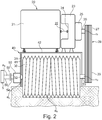
- FIG 2 the drive unit 20 is shown schematically.
- This drawing again shows the milling drum 30, specifically in a view transverse to the direction of travel, perpendicular to the image plane according to FIG Figure 1 in left view.
- the work tools 31 are shown schematically.
- the milling drum 30 is arranged in a milling drum box 40.
- the milling drum box 40 has side walls 41 and a top wall 42.
- the side walls 41 and the top wall 42 shield the milling drum 30 from the environment.
- an opening is provided on the milling drum box 40 through which the material can reach a conveying device, not shown, for example consisting of conveyor belts, in order to load the material onto a truck, for example.
- the milling drum 30 is rotatably mounted on the machine frame 11 or the milling drum box 40.
- the milling drum 30 has a drive shaft 33 and a bearing shaft 32.
- the milling drum 30 can be driven with the drive unit 20.
- the drive unit 20 comprises a drive motor 21, which is usually formed by an internal combustion engine.
- the drive motor 21 is connected to a pump transfer case 23 via a coupling element 22.
- the coupling element 22 can be arranged at least in some areas in a free space 24 of the pump transfer case.
- a fluid is pressurized in the pump transfer case. This fluid is fed via pressure lines to individual functional units of the road milling machine, for example the lifting columns 15 or to hydraulic motors of the chain drive 14.
- a switching device 25 is provided following the pump distributor gear 23.
- the drive motor 21 can optionally be coupled to a shaft 26 or decoupled from it.
- the shaft 26 carries a pulley 27, which is part of a transmission unit 28.
- the transmission unit 28 also includes a further belt pulley 29.
- the two belt pulleys 27, 29 are connected to one another via an endlessly rotating belt drive.
- the pulley 29 is held on the drive shaft 33 of the milling drum.
- the drive shaft 33 is guided through a lateral opening in the associated side wall 41 of the milling drum box 40.
- the drive shaft 33 is coupled directly or indirectly to the milling drum 30.
- a bearing shaft 32 is provided concentrically to the drive shaft 33 on the opposite side of the milling drum 30. The drive shaft 33 and the bearing shaft 32 together form the axis of rotation for the milling drum 30.
- FIG. 2 further illustrates that a transmission gear 50 is arranged outside the milling drum box.
- This transmission gear 50 can be designed as a gear with one or more gear stages or as a continuously variable transmission.
- the bearing shaft 32 leads directly to the input side of the transmission gear 50.
- a connecting piece 54 in the form of a shaft is arranged as a body of rotation.
- the connecting piece 54 establishes the connection to a coupling 55.
- the switchable coupling 55 can be operated from the operator's platform 12. It is also conceivable that a separately actuatable switching unit for operating the coupling 55 is provided in the vicinity of the milling drum box 40. Preferably, however, the switchable clutch 55 can be operated from the operator's platform 12, which makes operation considerably easier.
- the coupling 55 is connected to a kinetic mass 57 via a support shaft 56.
- the kinetic mass 57 is a weight that is connected to the support shaft 56. It is conceivable that the kinetic mass 57 is interchangeably coupled directly or indirectly to the support shaft 56.
- the transmission gear 50 is attached to the associated side wall 41 on the outside.
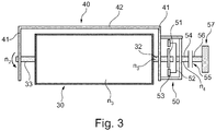
- the transmission gear 50 can for example be designed as a planetary gear.
- a drive element 51 which forms the sun gear of the planetary gear, is held on the bearing shaft 32.
- a planet carrier 52 with an output element 53 (planet gears) is held non-rotatably on the connecting piece 54.
- the planet carrier 52 carries how Figure 3 illustrates gears that mesh with the sun gear.
- the invention is of course not limited to the use of a planetary gear as a transmission gear 50. Rather, it is also conceivable that other gear forms are used.
- the drive motor 21 drives the pump transfer gear 23 via the coupling element 22.
- the shaft 26 is connected to the drive motor 21.
- the transmission unit 28 is driven at a speed n2, which can correspond to the speed n1 of the drive motor 21.
- the speed n2 is applied to the drive shaft 33.
- the speed n1 roughly corresponds to the speed n2.
- a different transmission ratio can also be selected.
- This speed n2 is now reduced to a lower speed n3 by means of a milling gear, not shown in the drawing, at which the milling drum 30 rotates. In conventional road milling machines, this transmission ratio between the higher speed n2 and the milling drum speed n3 is in the range between 10 and 30
- the transmission gear 20 now translates the speed n3 to a higher speed n4, which is applied to the connecting piece 54.
- this speed n4 is also applied to the support shaft 56, so that the kinetic mass 57 rotates at the higher speed n4.
- the kinetic mass 57 can therefore be coupled to the milling drum 30 via the clutch 55 and the transmission gear 50.
- the rotational energy generated during the rotational movement of the kinetic mass 57 is introduced into the milling drum 30. In this way, the kinetic energy of the milling drum 30 increases. This leads to an increased smoothness of the milling drum 30.
- FIG 4 an alternative embodiment of the invention is shown.
- the milling drum 40 is housed again in the milling drum box 40.
- the drive shaft 33 and the bearing shaft 32 are again rotatably coupled to the machine frame 11 or to the milling drum box 40.
- a milling gear 60 is accommodated in the space surrounded by the milling drum 30. With this milling gear 60, as explained above, the speed n2 of the belt pulley 29 can be reduced.
- the milling gear 60 can be designed as a planetary gear. It has a drive element 61, usually a gearwheel, which is connected to the drive shaft 33 in a rotationally fixed manner.
- One or more gears 62 (planet gears) mesh with this drive element 61 in order to reduce the speed.
- the drive shaft 33 has a connecting piece 63 which is connected to a support shaft 56 via a coupling 55.
- the support shaft 56 carries the kinetic mass 57.
- the speed n4 at which the kinetic mass 57 rotates corresponds to the speed n2 of the drive shaft 33 when the clutch 55 is closed.
- a transmission gear 50 is provided, which is before or after the clutch 55 is arranged and which translates the speed n2 of the drive shaft 33 to a higher speed n4 at which the kinetic mass 57 rotates.
- the kinetic mass 57 and the coupling 55 are arranged in a protected manner within the installation space surrounded by the milling drum 30.
- the milling gear 60 is also arranged in some areas within the milling drum box 40 and partially within the installation space surrounded by the milling drum 30.
- the axis with which the kinetic mass 57 rotates is aligned with the axis of rotation of the milling drum 30.
- these two axes of rotation are arranged at a distance from one another in parallel.
- these axes of rotation run at an angle to one another.
Landscapes
- Engineering & Computer Science (AREA)
- Architecture (AREA)
- Civil Engineering (AREA)
- Structural Engineering (AREA)
- Mechanical Engineering (AREA)
- Mining & Mineral Resources (AREA)
- Road Repair (AREA)
- Harvester Elements (AREA)
- Transmission Devices (AREA)
- Soil Working Implements (AREA)
Applications Claiming Priority (1)
| Application Number | Priority Date | Filing Date | Title |
|---|---|---|---|
| DE102019108759.7A DE102019108759B4 (de) | 2019-04-03 | 2019-04-03 | Bodenbearbeitungsmaschine |
Publications (2)
| Publication Number | Publication Date |
|---|---|
| EP3719202A1 true EP3719202A1 (fr) | 2020-10-07 |
| EP3719202B1 EP3719202B1 (fr) | 2021-09-15 |
Family
ID=69779931
Family Applications (1)
| Application Number | Title | Priority Date | Filing Date |
|---|---|---|---|
| EP20161354.4A Active EP3719202B1 (fr) | 2019-04-03 | 2020-03-06 | Machine de traitement du sol |
Country Status (4)
| Country | Link |
|---|---|
| US (1) | US11274401B2 (fr) |
| EP (1) | EP3719202B1 (fr) |
| CN (2) | CN111794063B (fr) |
| DE (1) | DE102019108759B4 (fr) |
Families Citing this family (5)
| Publication number | Priority date | Publication date | Assignee | Title |
|---|---|---|---|---|
| DE102019108759B4 (de) * | 2019-04-03 | 2024-06-20 | Wirtgen Gmbh | Bodenbearbeitungsmaschine |
| US11111639B2 (en) * | 2019-07-09 | 2021-09-07 | Caterpillar Paving Products Inc. | Construction machine with rotor load monitoring |
| EP4071303B1 (fr) * | 2021-04-06 | 2023-06-14 | BOMAG GmbH | Unité modulaire de fraise |
| US11885081B2 (en) * | 2021-08-11 | 2024-01-30 | Caterpillar Paving Products Inc. | Milling machine with hydraulically actuated rotor drive transmission |
| CN113863106B (zh) * | 2021-11-08 | 2023-03-14 | 江苏徐工工程机械研究院有限公司 | 铣刨装置和铣刨机 |
Citations (4)
| Publication number | Priority date | Publication date | Assignee | Title |
|---|---|---|---|---|
| US4006936A (en) | 1975-11-06 | 1977-02-08 | Dresser Industries, Inc. | Rotary cutter for a road planer |
| DE20122928U1 (de) | 2000-06-27 | 2010-04-08 | Wirtgen Gmbh | Baumaschine zum Bearbeiten von Bodenoberflächen |
| EP2354310A2 (fr) | 2010-02-08 | 2011-08-10 | Wirtgen GmbH | Contrôle de commande adaptative pour fraiseuse |
| DE102014118802A1 (de) | 2014-12-17 | 2016-06-23 | Wirtgen Gmbh | Arbeitseinrichtung |
Family Cites Families (15)
| Publication number | Priority date | Publication date | Assignee | Title |
|---|---|---|---|---|
| US508157A (en) | 1893-11-07 | William c | ||
| US1104502A (en) | 1911-12-05 | 1914-07-21 | John Hist | Water-ballast land-roller. |
| GB191511560A (en) | 1915-08-10 | 1916-11-10 | Naylorgraph Ltd | An Improved Apparatus for Displaying Advertisements, Signs, Notices, Outline Moving Pictures or the iike, or for Communicating Messages or Signaling both during Light and Darkness. |
| US1538550A (en) | 1924-12-17 | 1925-05-19 | Buch Mfg Co | Lawn roller |
| US2559427A (en) | 1945-11-02 | 1951-07-03 | Hastings George | Detachable road roller |
| US3008389A (en) | 1959-04-27 | 1961-11-14 | William L Hicks | Ballasted earth compaction equipment |
| US3078730A (en) | 1961-01-06 | 1963-02-26 | Bell Intercontinental Corp | Vibratory device and amplitude adjustment means |
| US3238799A (en) * | 1962-07-12 | 1966-03-08 | Tyler Inc W S | Double wedge ring adjustment means |
| DE19547698C2 (de) | 1995-12-20 | 2000-08-17 | Wirtgen Gmbh | Vorrichtung und Verfahren zum Abfräsen von harten Oberflächen, insbesondere von Straßenbelägen |
| US5846176A (en) | 1997-04-08 | 1998-12-08 | Zieger; Robert V. | Roller tool for concrete finishing |
| US6755482B2 (en) | 2001-05-25 | 2004-06-29 | Surface Preparation Technologies, Inc. | Cutting machine with flywheel gearbox design and method for use |
| US7540689B1 (en) * | 2007-01-16 | 2009-06-02 | Major Sr William J | Counterweight system |
| US10480135B2 (en) * | 2017-01-03 | 2019-11-19 | Roadtec, Inc. | Cold in-place recycling with heating assembly including a heater for asphalt cement and a heat-modifying component |
| CN109162185A (zh) | 2018-09-20 | 2019-01-08 | 三汽车制造有限公司 | 铣刨鼓滚筒、铣刨鼓及铣刨机 |
| DE102019108759B4 (de) * | 2019-04-03 | 2024-06-20 | Wirtgen Gmbh | Bodenbearbeitungsmaschine |
-
2019
- 2019-04-03 DE DE102019108759.7A patent/DE102019108759B4/de active Active
-
2020
- 2020-03-06 EP EP20161354.4A patent/EP3719202B1/fr active Active
- 2020-03-20 US US16/824,774 patent/US11274401B2/en active Active
- 2020-03-27 CN CN202010227829.0A patent/CN111794063B/zh active Active
- 2020-03-27 CN CN202020414684.0U patent/CN212052240U/zh not_active Withdrawn - After Issue
Patent Citations (4)
| Publication number | Priority date | Publication date | Assignee | Title |
|---|---|---|---|---|
| US4006936A (en) | 1975-11-06 | 1977-02-08 | Dresser Industries, Inc. | Rotary cutter for a road planer |
| DE20122928U1 (de) | 2000-06-27 | 2010-04-08 | Wirtgen Gmbh | Baumaschine zum Bearbeiten von Bodenoberflächen |
| EP2354310A2 (fr) | 2010-02-08 | 2011-08-10 | Wirtgen GmbH | Contrôle de commande adaptative pour fraiseuse |
| DE102014118802A1 (de) | 2014-12-17 | 2016-06-23 | Wirtgen Gmbh | Arbeitseinrichtung |
Also Published As
| Publication number | Publication date |
|---|---|
| CN111794063B (zh) | 2022-03-18 |
| CN111794063A (zh) | 2020-10-20 |
| US11274401B2 (en) | 2022-03-15 |
| EP3719202B1 (fr) | 2021-09-15 |
| US20200318297A1 (en) | 2020-10-08 |
| CN212052240U (zh) | 2020-12-01 |
| DE102019108759B4 (de) | 2024-06-20 |
| DE102019108759A1 (de) | 2020-10-08 |
Similar Documents
| Publication | Publication Date | Title |
|---|---|---|
| EP3719202B1 (fr) | Machine de traitement du sol | |
| EP1983105B1 (fr) | Engin de travaux publics automoteur, en particulier machine de fraisage, recycleur ou stabilisateur | |
| EP3869067B1 (fr) | Machine de traitement du sol avec une transmission pourvue de boîte de vitesses à deux rapports en deux pièces à des ratios de transmission seulement légèrement différents | |
| DE2822686C2 (fr) | ||
| EP3901373B1 (fr) | Unité de remplacement destinée au traitement texturant de surface du sol et la machine de construction routière dotée d'une telle unité de remplacement | |
| DE102011116268A1 (de) | Selbstfahrende Baumaschine | |
| EP3034699B1 (fr) | Dispositif de travail | |
| DE19858124C2 (de) | Radantrieb | |
| DE102012012738A1 (de) | Bodenbearbeitungsmaschine | |
| EP3365497B1 (fr) | Dispositif d'entraînement pour engin de chantier, et engin de chantier | |
| EP3889355A1 (fr) | Engin de construction automoteur et méthode de travail de revêtement de sol | |
| EP0681063A2 (fr) | Fraiseuse | |
| EP3034348A1 (fr) | Boîte de transfert destinée à répartir un couple sur au moins un premier et un second arbre primaire d'un véhicule automobile | |
| DE102006020663A1 (de) | Anbaugerät für Arbeitsmaschinen | |
| DE102013112182A1 (de) | Fahrzeug für den Materialumschlag | |
| DE2940523A1 (de) | Antriebsaggregat fuer loeffelbagger u.ae. erdbearbeitungsmaschinen | |
| EP4332304B1 (fr) | Machine automotrice de traitement du sol avec moteurs jumelés et procédé de fonctionnement de ladite machine | |
| EP3736158A1 (fr) | Agencement de boîte de prise de force | |
| DE102019216037B4 (de) | Doppelantrieb-raupenkettensystem | |
| DE2541838A1 (de) | Walzenschraemmaschine bzw. vortriebsmaschine fuer den untertagebergbau | |
| DE102018001858A1 (de) | Drehmomentübertragungsanordnung, Antriebsstrang mit einer solchen Drehmomentübertragungsanordnung und Fliehkraftpendeleinrichtung für eine solche Drehmomentübertragungsanordnung | |
| DE102022126637A1 (de) | Anbaufräseinheit mit zueinander winklig stehenden Querschneidköpfen und Abtriebszahnrädern mit Belevoid-Verzahnung | |
| EP2348806A2 (fr) | Équipement auxiliaire pour véhicules tout terrain pour le paillage ou le déminage | |
| DE2362405A1 (de) | Vibrationswalze zum bodenverdichten | |
| DE1784023A1 (de) | Strassendeckenfraesmaschine |
Legal Events
| Date | Code | Title | Description |
|---|---|---|---|
| PUAI | Public reference made under article 153(3) epc to a published international application that has entered the european phase |
Free format text: ORIGINAL CODE: 0009012 |
|
| STAA | Information on the status of an ep patent application or granted ep patent |
Free format text: STATUS: THE APPLICATION HAS BEEN PUBLISHED |
|
| AK | Designated contracting states |
Kind code of ref document: A1 Designated state(s): AL AT BE BG CH CY CZ DE DK EE ES FI FR GB GR HR HU IE IS IT LI LT LU LV MC MK MT NL NO PL PT RO RS SE SI SK SM TR |
|
| AX | Request for extension of the european patent |
Extension state: BA ME |
|
| STAA | Information on the status of an ep patent application or granted ep patent |
Free format text: STATUS: REQUEST FOR EXAMINATION WAS MADE |
|
| 17P | Request for examination filed |
Effective date: 20210407 |
|
| RBV | Designated contracting states (corrected) |
Designated state(s): AL AT BE BG CH CY CZ DE DK EE ES FI FR GB GR HR HU IE IS IT LI LT LU LV MC MK MT NL NO PL PT RO RS SE SI SK SM TR |
|
| GRAP | Despatch of communication of intention to grant a patent |
Free format text: ORIGINAL CODE: EPIDOSNIGR1 |
|
| STAA | Information on the status of an ep patent application or granted ep patent |
Free format text: STATUS: GRANT OF PATENT IS INTENDED |
|
| RIC1 | Information provided on ipc code assigned before grant |
Ipc: E21C 27/24 20060101ALI20210520BHEP Ipc: E01C 23/088 20060101AFI20210520BHEP |
|
| INTG | Intention to grant announced |
Effective date: 20210608 |
|
| GRAS | Grant fee paid |
Free format text: ORIGINAL CODE: EPIDOSNIGR3 |
|
| GRAA | (expected) grant |
Free format text: ORIGINAL CODE: 0009210 |
|
| STAA | Information on the status of an ep patent application or granted ep patent |
Free format text: STATUS: THE PATENT HAS BEEN GRANTED |
|
| AK | Designated contracting states |
Kind code of ref document: B1 Designated state(s): AL AT BE BG CH CY CZ DE DK EE ES FI FR GB GR HR HU IE IS IT LI LT LU LV MC MK MT NL NO PL PT RO RS SE SI SK SM TR |
|
| REG | Reference to a national code |
Ref country code: CH Ref legal event code: EP |
|
| REG | Reference to a national code |
Ref country code: DE Ref legal event code: R096 Ref document number: 502020000187 Country of ref document: DE |
|
| REG | Reference to a national code |
Ref country code: IE Ref legal event code: FG4D Free format text: LANGUAGE OF EP DOCUMENT: GERMAN |
|
| REG | Reference to a national code |
Ref country code: AT Ref legal event code: REF Ref document number: 1430619 Country of ref document: AT Kind code of ref document: T Effective date: 20211015 |
|
| REG | Reference to a national code |
Ref country code: LT Ref legal event code: MG9D |
|
| REG | Reference to a national code |
Ref country code: NL Ref legal event code: MP Effective date: 20210915 |
|
| PG25 | Lapsed in a contracting state [announced via postgrant information from national office to epo] |
Ref country code: RS Free format text: LAPSE BECAUSE OF FAILURE TO SUBMIT A TRANSLATION OF THE DESCRIPTION OR TO PAY THE FEE WITHIN THE PRESCRIBED TIME-LIMIT Effective date: 20210915 Ref country code: SE Free format text: LAPSE BECAUSE OF FAILURE TO SUBMIT A TRANSLATION OF THE DESCRIPTION OR TO PAY THE FEE WITHIN THE PRESCRIBED TIME-LIMIT Effective date: 20210915 Ref country code: NO Free format text: LAPSE BECAUSE OF FAILURE TO SUBMIT A TRANSLATION OF THE DESCRIPTION OR TO PAY THE FEE WITHIN THE PRESCRIBED TIME-LIMIT Effective date: 20211215 Ref country code: FI Free format text: LAPSE BECAUSE OF FAILURE TO SUBMIT A TRANSLATION OF THE DESCRIPTION OR TO PAY THE FEE WITHIN THE PRESCRIBED TIME-LIMIT Effective date: 20210915 Ref country code: HR Free format text: LAPSE BECAUSE OF FAILURE TO SUBMIT A TRANSLATION OF THE DESCRIPTION OR TO PAY THE FEE WITHIN THE PRESCRIBED TIME-LIMIT Effective date: 20210915 Ref country code: BG Free format text: LAPSE BECAUSE OF FAILURE TO SUBMIT A TRANSLATION OF THE DESCRIPTION OR TO PAY THE FEE WITHIN THE PRESCRIBED TIME-LIMIT Effective date: 20211215 Ref country code: LT Free format text: LAPSE BECAUSE OF FAILURE TO SUBMIT A TRANSLATION OF THE DESCRIPTION OR TO PAY THE FEE WITHIN THE PRESCRIBED TIME-LIMIT Effective date: 20210915 |
|
| PG25 | Lapsed in a contracting state [announced via postgrant information from national office to epo] |
Ref country code: LV Free format text: LAPSE BECAUSE OF FAILURE TO SUBMIT A TRANSLATION OF THE DESCRIPTION OR TO PAY THE FEE WITHIN THE PRESCRIBED TIME-LIMIT Effective date: 20210915 Ref country code: GR Free format text: LAPSE BECAUSE OF FAILURE TO SUBMIT A TRANSLATION OF THE DESCRIPTION OR TO PAY THE FEE WITHIN THE PRESCRIBED TIME-LIMIT Effective date: 20211216 |
|
| PG25 | Lapsed in a contracting state [announced via postgrant information from national office to epo] |
Ref country code: IS Free format text: LAPSE BECAUSE OF FAILURE TO SUBMIT A TRANSLATION OF THE DESCRIPTION OR TO PAY THE FEE WITHIN THE PRESCRIBED TIME-LIMIT Effective date: 20220115 Ref country code: SM Free format text: LAPSE BECAUSE OF FAILURE TO SUBMIT A TRANSLATION OF THE DESCRIPTION OR TO PAY THE FEE WITHIN THE PRESCRIBED TIME-LIMIT Effective date: 20210915 Ref country code: SK Free format text: LAPSE BECAUSE OF FAILURE TO SUBMIT A TRANSLATION OF THE DESCRIPTION OR TO PAY THE FEE WITHIN THE PRESCRIBED TIME-LIMIT Effective date: 20210915 Ref country code: RO Free format text: LAPSE BECAUSE OF FAILURE TO SUBMIT A TRANSLATION OF THE DESCRIPTION OR TO PAY THE FEE WITHIN THE PRESCRIBED TIME-LIMIT Effective date: 20210915 Ref country code: PT Free format text: LAPSE BECAUSE OF FAILURE TO SUBMIT A TRANSLATION OF THE DESCRIPTION OR TO PAY THE FEE WITHIN THE PRESCRIBED TIME-LIMIT Effective date: 20220117 Ref country code: PL Free format text: LAPSE BECAUSE OF FAILURE TO SUBMIT A TRANSLATION OF THE DESCRIPTION OR TO PAY THE FEE WITHIN THE PRESCRIBED TIME-LIMIT Effective date: 20210915 Ref country code: NL Free format text: LAPSE BECAUSE OF FAILURE TO SUBMIT A TRANSLATION OF THE DESCRIPTION OR TO PAY THE FEE WITHIN THE PRESCRIBED TIME-LIMIT Effective date: 20210915 Ref country code: ES Free format text: LAPSE BECAUSE OF FAILURE TO SUBMIT A TRANSLATION OF THE DESCRIPTION OR TO PAY THE FEE WITHIN THE PRESCRIBED TIME-LIMIT Effective date: 20210915 Ref country code: EE Free format text: LAPSE BECAUSE OF FAILURE TO SUBMIT A TRANSLATION OF THE DESCRIPTION OR TO PAY THE FEE WITHIN THE PRESCRIBED TIME-LIMIT Effective date: 20210915 Ref country code: CZ Free format text: LAPSE BECAUSE OF FAILURE TO SUBMIT A TRANSLATION OF THE DESCRIPTION OR TO PAY THE FEE WITHIN THE PRESCRIBED TIME-LIMIT Effective date: 20210915 Ref country code: AL Free format text: LAPSE BECAUSE OF FAILURE TO SUBMIT A TRANSLATION OF THE DESCRIPTION OR TO PAY THE FEE WITHIN THE PRESCRIBED TIME-LIMIT Effective date: 20210915 |
|
| REG | Reference to a national code |
Ref country code: DE Ref legal event code: R097 Ref document number: 502020000187 Country of ref document: DE |
|
| PLBE | No opposition filed within time limit |
Free format text: ORIGINAL CODE: 0009261 |
|
| STAA | Information on the status of an ep patent application or granted ep patent |
Free format text: STATUS: NO OPPOSITION FILED WITHIN TIME LIMIT |
|
| PG25 | Lapsed in a contracting state [announced via postgrant information from national office to epo] |
Ref country code: DK Free format text: LAPSE BECAUSE OF FAILURE TO SUBMIT A TRANSLATION OF THE DESCRIPTION OR TO PAY THE FEE WITHIN THE PRESCRIBED TIME-LIMIT Effective date: 20210915 |
|
| 26N | No opposition filed |
Effective date: 20220616 |
|
| PG25 | Lapsed in a contracting state [announced via postgrant information from national office to epo] |
Ref country code: SI Free format text: LAPSE BECAUSE OF FAILURE TO SUBMIT A TRANSLATION OF THE DESCRIPTION OR TO PAY THE FEE WITHIN THE PRESCRIBED TIME-LIMIT Effective date: 20210915 |
|
| PG25 | Lapsed in a contracting state [announced via postgrant information from national office to epo] |
Ref country code: MC Free format text: LAPSE BECAUSE OF FAILURE TO SUBMIT A TRANSLATION OF THE DESCRIPTION OR TO PAY THE FEE WITHIN THE PRESCRIBED TIME-LIMIT Effective date: 20210915 |
|
| REG | Reference to a national code |
Ref country code: BE Ref legal event code: MM Effective date: 20220331 |
|
| PG25 | Lapsed in a contracting state [announced via postgrant information from national office to epo] |
Ref country code: LU Free format text: LAPSE BECAUSE OF NON-PAYMENT OF DUE FEES Effective date: 20220306 Ref country code: IE Free format text: LAPSE BECAUSE OF NON-PAYMENT OF DUE FEES Effective date: 20220306 |
|
| PG25 | Lapsed in a contracting state [announced via postgrant information from national office to epo] |
Ref country code: BE Free format text: LAPSE BECAUSE OF NON-PAYMENT OF DUE FEES Effective date: 20220331 |
|
| P01 | Opt-out of the competence of the unified patent court (upc) registered |
Effective date: 20230525 |
|
| REG | Reference to a national code |
Ref country code: CH Ref legal event code: PL |
|
| PG25 | Lapsed in a contracting state [announced via postgrant information from national office to epo] |
Ref country code: LI Free format text: LAPSE BECAUSE OF NON-PAYMENT OF DUE FEES Effective date: 20230331 Ref country code: CH Free format text: LAPSE BECAUSE OF NON-PAYMENT OF DUE FEES Effective date: 20230331 |
|
| PG25 | Lapsed in a contracting state [announced via postgrant information from national office to epo] |
Ref country code: MK Free format text: LAPSE BECAUSE OF FAILURE TO SUBMIT A TRANSLATION OF THE DESCRIPTION OR TO PAY THE FEE WITHIN THE PRESCRIBED TIME-LIMIT Effective date: 20210915 Ref country code: CY Free format text: LAPSE BECAUSE OF FAILURE TO SUBMIT A TRANSLATION OF THE DESCRIPTION OR TO PAY THE FEE WITHIN THE PRESCRIBED TIME-LIMIT Effective date: 20210915 |
|
| PG25 | Lapsed in a contracting state [announced via postgrant information from national office to epo] |
Ref country code: HU Free format text: LAPSE BECAUSE OF FAILURE TO SUBMIT A TRANSLATION OF THE DESCRIPTION OR TO PAY THE FEE WITHIN THE PRESCRIBED TIME-LIMIT; INVALID AB INITIO Effective date: 20200306 |
|
| PG25 | Lapsed in a contracting state [announced via postgrant information from national office to epo] |
Ref country code: MT Free format text: LAPSE BECAUSE OF FAILURE TO SUBMIT A TRANSLATION OF THE DESCRIPTION OR TO PAY THE FEE WITHIN THE PRESCRIBED TIME-LIMIT Effective date: 20210915 |
|
| PGFP | Annual fee paid to national office [announced via postgrant information from national office to epo] |
Ref country code: AT Payment date: 20250417 Year of fee payment: 5 |
|
| PGFP | Annual fee paid to national office [announced via postgrant information from national office to epo] |
Ref country code: IT Payment date: 20250331 Year of fee payment: 6 |
|
| PG25 | Lapsed in a contracting state [announced via postgrant information from national office to epo] |
Ref country code: TR Free format text: LAPSE BECAUSE OF FAILURE TO SUBMIT A TRANSLATION OF THE DESCRIPTION OR TO PAY THE FEE WITHIN THE PRESCRIBED TIME-LIMIT Effective date: 20210915 |
|
| PGFP | Annual fee paid to national office [announced via postgrant information from national office to epo] |
Ref country code: GB Payment date: 20260324 Year of fee payment: 7 |
|
| PGFP | Annual fee paid to national office [announced via postgrant information from national office to epo] |
Ref country code: DE Payment date: 20260320 Year of fee payment: 7 |
|
| PGFP | Annual fee paid to national office [announced via postgrant information from national office to epo] |
Ref country code: FR Payment date: 20260324 Year of fee payment: 7 |