EP3719232B1 - Élément d'ancrage et ensemble d'ancrage le comprenant - Google Patents
Élément d'ancrage et ensemble d'ancrage le comprenant Download PDFInfo
- Publication number
- EP3719232B1 EP3719232B1 EP17814804.5A EP17814804A EP3719232B1 EP 3719232 B1 EP3719232 B1 EP 3719232B1 EP 17814804 A EP17814804 A EP 17814804A EP 3719232 B1 EP3719232 B1 EP 3719232B1
- Authority
- EP
- European Patent Office
- Prior art keywords
- securing
- shaft
- ring
- case
- slots
- Prior art date
- Legal status (The legal status is an assumption and is not a legal conclusion. Google has not performed a legal analysis and makes no representation as to the accuracy of the status listed.)
- Active
Links
Images




Classifications
-
- B—PERFORMING OPERATIONS; TRANSPORTING
- B66—HOISTING; LIFTING; HAULING
- B66C—CRANES; LOAD-ENGAGING ELEMENTS OR DEVICES FOR CRANES, CAPSTANS, WINCHES, OR TACKLES
- B66C1/00—Load-engaging elements or devices attached to lifting or lowering gear of cranes or adapted for connection therewith for transmitting lifting forces to articles or groups of articles
- B66C1/10—Load-engaging elements or devices attached to lifting or lowering gear of cranes or adapted for connection therewith for transmitting lifting forces to articles or groups of articles by mechanical means
- B66C1/62—Load-engaging elements or devices attached to lifting or lowering gear of cranes or adapted for connection therewith for transmitting lifting forces to articles or groups of articles by mechanical means comprising article-engaging members of a shape complementary to that of the articles to be handled
- B66C1/66—Load-engaging elements or devices attached to lifting or lowering gear of cranes or adapted for connection therewith for transmitting lifting forces to articles or groups of articles by mechanical means comprising article-engaging members of a shape complementary to that of the articles to be handled for engaging holes, recesses, or abutments on articles specially provided for facilitating handling thereof
-
- B—PERFORMING OPERATIONS; TRANSPORTING
- B66—HOISTING; LIFTING; HAULING
- B66C—CRANES; LOAD-ENGAGING ELEMENTS OR DEVICES FOR CRANES, CAPSTANS, WINCHES, OR TACKLES
- B66C1/00—Load-engaging elements or devices attached to lifting or lowering gear of cranes or adapted for connection therewith for transmitting lifting forces to articles or groups of articles
- B66C1/10—Load-engaging elements or devices attached to lifting or lowering gear of cranes or adapted for connection therewith for transmitting lifting forces to articles or groups of articles by mechanical means
- B66C1/62—Load-engaging elements or devices attached to lifting or lowering gear of cranes or adapted for connection therewith for transmitting lifting forces to articles or groups of articles by mechanical means comprising article-engaging members of a shape complementary to that of the articles to be handled
- B66C1/66—Load-engaging elements or devices attached to lifting or lowering gear of cranes or adapted for connection therewith for transmitting lifting forces to articles or groups of articles by mechanical means comprising article-engaging members of a shape complementary to that of the articles to be handled for engaging holes, recesses, or abutments on articles specially provided for facilitating handling thereof
- B66C1/666—Load-engaging elements or devices attached to lifting or lowering gear of cranes or adapted for connection therewith for transmitting lifting forces to articles or groups of articles by mechanical means comprising article-engaging members of a shape complementary to that of the articles to be handled for engaging holes, recesses, or abutments on articles specially provided for facilitating handling thereof for connection to anchor inserts embedded in concrete structures
-
- E—FIXED CONSTRUCTIONS
- E04—BUILDING
- E04G—SCAFFOLDING; FORMS; SHUTTERING; BUILDING IMPLEMENTS OR AIDS, OR THEIR USE; HANDLING BUILDING MATERIALS ON THE SITE; REPAIRING, BREAKING-UP OR OTHER WORK ON EXISTING BUILDINGS
- E04G21/00—Preparing, conveying, or working-up building materials or building elements in situ; Other devices or measures for constructional work
- E04G21/32—Safety or protective measures for persons during the construction of buildings
- E04G21/3261—Safety-nets; Safety mattresses; Arrangements on buildings for connecting safety-lines
- E04G21/3276—Arrangements on buildings for connecting safety-lines
-
- E—FIXED CONSTRUCTIONS
- E04—BUILDING
- E04G—SCAFFOLDING; FORMS; SHUTTERING; BUILDING IMPLEMENTS OR AIDS, OR THEIR USE; HANDLING BUILDING MATERIALS ON THE SITE; REPAIRING, BREAKING-UP OR OTHER WORK ON EXISTING BUILDINGS
- E04G5/00—Component parts or accessories for scaffolds
- E04G5/04—Means for fastening, supporting, or bracing scaffolds on or against building constructions
-
- E—FIXED CONSTRUCTIONS
- E04—BUILDING
- E04G—SCAFFOLDING; FORMS; SHUTTERING; BUILDING IMPLEMENTS OR AIDS, OR THEIR USE; HANDLING BUILDING MATERIALS ON THE SITE; REPAIRING, BREAKING-UP OR OTHER WORK ON EXISTING BUILDINGS
- E04G5/00—Component parts or accessories for scaffolds
- E04G5/04—Means for fastening, supporting, or bracing scaffolds on or against building constructions
- E04G5/046—Means for fastening, supporting, or bracing scaffolds on or against building constructions for fastening scaffoldings on walls
-
- F—MECHANICAL ENGINEERING; LIGHTING; HEATING; WEAPONS; BLASTING
- F16—ENGINEERING ELEMENTS AND UNITS; GENERAL MEASURES FOR PRODUCING AND MAINTAINING EFFECTIVE FUNCTIONING OF MACHINES OR INSTALLATIONS; THERMAL INSULATION IN GENERAL
- F16B—DEVICES FOR FASTENING OR SECURING CONSTRUCTIONAL ELEMENTS OR MACHINE PARTS TOGETHER, e.g. NAILS, BOLTS, CIRCLIPS, CLAMPS, CLIPS OR WEDGES; JOINTS OR JOINTING
- F16B13/00—Dowels or other devices fastened in walls or the like by inserting them in holes made therein for that purpose
- F16B13/04—Dowels or other devices fastened in walls or the like by inserting them in holes made therein for that purpose with parts gripping in the hole or behind the reverse side of the wall after inserting from the front
- F16B13/08—Dowels or other devices fastened in walls or the like by inserting them in holes made therein for that purpose with parts gripping in the hole or behind the reverse side of the wall after inserting from the front with separate or non-separate gripping parts moved into their final position in relation to the body of the device without further manual operation
- F16B13/0833—Dowels or other devices fastened in walls or the like by inserting them in holes made therein for that purpose with parts gripping in the hole or behind the reverse side of the wall after inserting from the front with separate or non-separate gripping parts moved into their final position in relation to the body of the device without further manual operation with segments or fingers expanding or tilting into an undercut hole
-
- F—MECHANICAL ENGINEERING; LIGHTING; HEATING; WEAPONS; BLASTING
- F16—ENGINEERING ELEMENTS AND UNITS; GENERAL MEASURES FOR PRODUCING AND MAINTAINING EFFECTIVE FUNCTIONING OF MACHINES OR INSTALLATIONS; THERMAL INSULATION IN GENERAL
- F16B—DEVICES FOR FASTENING OR SECURING CONSTRUCTIONAL ELEMENTS OR MACHINE PARTS TOGETHER, e.g. NAILS, BOLTS, CIRCLIPS, CLAMPS, CLIPS OR WEDGES; JOINTS OR JOINTING
- F16B2/00—Friction-grip releasable fastenings
- F16B2/02—Clamps, i.e. with gripping action effected by positive means other than the inherent resistance to deformation of the material of the fastening
- F16B2/04—Clamps, i.e. with gripping action effected by positive means other than the inherent resistance to deformation of the material of the fastening internal, i.e. with spreading action
-
- F—MECHANICAL ENGINEERING; LIGHTING; HEATING; WEAPONS; BLASTING
- F16—ENGINEERING ELEMENTS AND UNITS; GENERAL MEASURES FOR PRODUCING AND MAINTAINING EFFECTIVE FUNCTIONING OF MACHINES OR INSTALLATIONS; THERMAL INSULATION IN GENERAL
- F16B—DEVICES FOR FASTENING OR SECURING CONSTRUCTIONAL ELEMENTS OR MACHINE PARTS TOGETHER, e.g. NAILS, BOLTS, CIRCLIPS, CLAMPS, CLIPS OR WEDGES; JOINTS OR JOINTING
- F16B41/00—Measures against loss of bolts, nuts, or pins; Measures against unauthorised operation of bolts, nuts or pins
-
- F—MECHANICAL ENGINEERING; LIGHTING; HEATING; WEAPONS; BLASTING
- F16—ENGINEERING ELEMENTS AND UNITS; GENERAL MEASURES FOR PRODUCING AND MAINTAINING EFFECTIVE FUNCTIONING OF MACHINES OR INSTALLATIONS; THERMAL INSULATION IN GENERAL
- F16B—DEVICES FOR FASTENING OR SECURING CONSTRUCTIONAL ELEMENTS OR MACHINE PARTS TOGETHER, e.g. NAILS, BOLTS, CIRCLIPS, CLAMPS, CLIPS OR WEDGES; JOINTS OR JOINTING
- F16B45/00—Hooks; Eyes
- F16B45/005—Hooks; Eyes characterised by the material
- F16B45/015—Hooks; Eyes characterised by the material sheet metal
-
- F—MECHANICAL ENGINEERING; LIGHTING; HEATING; WEAPONS; BLASTING
- F16—ENGINEERING ELEMENTS AND UNITS; GENERAL MEASURES FOR PRODUCING AND MAINTAINING EFFECTIVE FUNCTIONING OF MACHINES OR INSTALLATIONS; THERMAL INSULATION IN GENERAL
- F16B—DEVICES FOR FASTENING OR SECURING CONSTRUCTIONAL ELEMENTS OR MACHINE PARTS TOGETHER, e.g. NAILS, BOLTS, CIRCLIPS, CLAMPS, CLIPS OR WEDGES; JOINTS OR JOINTING
- F16B45/00—Hooks; Eyes
- F16B45/06—Hooks with two symmetrically-pivoting hook parts within the same locking cavity
-
- F—MECHANICAL ENGINEERING; LIGHTING; HEATING; WEAPONS; BLASTING
- F16—ENGINEERING ELEMENTS AND UNITS; GENERAL MEASURES FOR PRODUCING AND MAINTAINING EFFECTIVE FUNCTIONING OF MACHINES OR INSTALLATIONS; THERMAL INSULATION IN GENERAL
- F16B—DEVICES FOR FASTENING OR SECURING CONSTRUCTIONAL ELEMENTS OR MACHINE PARTS TOGETHER, e.g. NAILS, BOLTS, CIRCLIPS, CLAMPS, CLIPS OR WEDGES; JOINTS OR JOINTING
- F16B13/00—Dowels or other devices fastened in walls or the like by inserting them in holes made therein for that purpose
- F16B2013/007—Dowels or other devices fastened in walls or the like by inserting them in holes made therein for that purpose to be fastened in undercut holes
Definitions
- the object of the present invention is a embeddable security anchor, of the type of those intended to be installed in a wall or structural element to form a secure point for hooking lifelines or cables, safety harnesses, elements for lifting or securing loads and in general for the safe hold of any kind of load.
- anchor points for hooking safety elements, personal protection or fastening loads are commonly installed on either a temporary or permanent basis.
- the most common anchors are formed by rings joined to a support base or plate, which is fixed to an existing construction by means of different kinds of screws and plugs, such as expansion plugs, chemical plugs, etc.
- a scissor-type securing element comprising two hooks pivotably connected together by a rotary shaft, a distal part being defined in each hook on one side of the shaft and a proximal part being defined on the other side of the shaft, the distal parts being intended to be introduced in a case embedded in a structure, each distal part being provided with a tooth and each proximal part being provided with a penetrating slot, in which an insertion configuration is defined, in which the hooks are superposed and a securing configuration in which the teeth are in a more separated position and the hooks project so as to remain retained in an inner support surface of the case, the slots being arranged so that in the insertion configuration the ends of the slots closest to the shaft overlap and in the securing configuration the ends of the slots furthest from the shaft overlap, in which the securing element comprises a shackle, the shackle being provided with a ring for supporting the load, two ring ends and
- the present invention aims to provide new functions to this type of anchors.
- the present invention proposes a scissor-type securing element according to claim 1 comprising two hooks pivotably connected together by a rotary shaft, a distal part being defined in each hook on one side of the shaft and a proximal part being defined on the other side of the shaft, the distal parts being intended to be introduced in a case embedded in a structure, each distal part being provided with a tooth and each proximal part being provided with a penetrating slot, in which an insertion configuration is defined, in which the hooks are superposed and a securing configuration in which the teeth are in a more separated position and the hooks project so as to remain retained in an inner support surface of the case, the slots being arranged so that in the insertion configuration the ends of the slots closest to the shaft overlap and in the securing configuration the ends of the slots furthest from the shaft overlap, in which the securing element comprises a shackle, the shackle being provided with a ring for supporting the
- This structure allows in the insertion configuration, to fit the ends of the shaft in the housings of the ends or ears of the ring, to prevent the rotation of the shackle in relation to the hooks that constitute the securing element, so that it results in a single piece with no moving parts, which facilitates its handling for insertion.
- the ends of the pins leave the housings and then the rotation of the shackle in relation to the hooks is allowed. That is, in the securing position, these can no longer rotate with each other, but the shackle can do so, and be oriented in the direction of the applied forces.
- Another advantage is that, since the shackle is part of the securing element, it is already dimensioned to fit perfectly in the slots, which does not happen with other devices of the state of the art in which an added shackle is used for its insertion into the slots.
- the ends of the slots furthest from the shaft are provided on their inner surface with a frangible element.
- This frangible element constitutes an indicator, which must be dimensioned according to the maximum permissible load, according to the longitudinal direction, of the securing element.
- the frangible member is a tab attached at its ends to the internal walls of the slot end or a protruding attachment disposed at the end of the slot.
- the shackle ring is disposed in an oblique plane to the general plane of the securing element, so that the joints between the ring and the ring ends are made on an upper side of the key on opposite sides thereof.
- the securing element is symmetrical with regard to its longitudinal direction.
- the invention also proposes a embeddable security anchor assembly of the type intended to be fixed to a wall or structural element to form a secure point for hooking lifelines, safety harnesses, elements for lifting or securing loads and in general for the safe hold of any kind of load, the securing assembly being provided with an securing element according to any of the variants of the anchor object of the invention described above, and a case embedded in a structure, and further comprising a positioning disk, the positioning disk being provided with first removable attachment means to the inner side of the mould of the wall formwork and with second removable attachment means to the case.
- This structure allows the placement with great precision, in a very simple way and with reduced costs, of the case in the wall, and in particular to improve the quality of the anchor.
- the case is elongated, its cross section is rectangular, its distal part comprises at least two side widening, its proximal part comprises an outer mouth complementary to the positioning disc and third removable attachment means complementary to the second attachment means of the positioning disc.
- each of the hooks comprises teeth at different levels, so that different securing levels are defined.
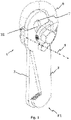
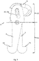
- the present invention relates to a scissor-type securing element 1, comprising two hooks 2, 3 pivotably connected together by a rotary shaft 4.
- the hooks are metal, elongated plates with rounded ends, so that they have an oblong outline.
- the two hooks have the same shape, so that when overlapping, their envelope coincides.
- a distal part G1 is defined on one side of the shaft 4
- a proximal part G2 is defined on the other side of the shaft 4.
- the distal parts which are rounded, are intended to be inserted in a case 5 embedded in a structure E.
- Each distal part G1 is provided with a tooth 21, 31 and each proximal part with a penetrating slot 22, 32.
- the grooves are elongated, preferably arched, with rounded ends. Another way to describe them is like slotted holes.
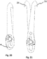
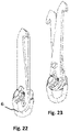
- an insertion configuration P1 is defined, as shown in Figures 1 , 17 and 20 , in which the hooks 2, 3 overlap and an securing configuration P2, shown for example in Figures 2 , 3 , 18, 19 , 21 and 25 , in which the teeth 21, 31 are in a more separated position and the hooks 2, 3 protrude to be retained on an inner support surface 51 of the case 5.
- the slots 22, 32 are arranged so that in the insertion configuration the ends of the slots 22, 32 closest to the shaft 4 overlap and in the securing configuration the ends of the slots 22, 32 furthest from the axis 4 overlap.
- the securing element 1 comprises a shackle 6, which is provided with a ring 61 for supporting the load, two ring ends 62, 63 and a key 64 supported by the two ends 62, 63.
- the key 64 as can be seen in Figure 3 , is inserted in the slots 22, 32.
- the ends 41, 42 of the shaft 4 protrude laterally, and the ring ends 62, 63 are provided with a housing 65 with a complementary shape of the ends 41, 42 of the shaft 4, so that in the insertion configuration, each of the ends 41, 42 of the shaft 4 is inserted into a housing 65.
- the housing can be designed to receive an angular sector of the smallest end of the key, provided that it allows a support and a locking of the ring end with regard to the hook.
- the essential thing is that there is a support surface that prevents the rotation of the ring in each of the directions.
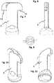
- a frangible element 7 which may be a tab joined at its ends to the internal walls of the end of the slot 22, 32, as shown in Figure 1 , or a projecting attachment disposed at the end of the slot 22, 32, as described in Figure 10 .
- the frangible element 7, apart from an indicator, is an energy dissipater in the event of a fall.
- it can be designed so that its rupture involves a work, so that the requests caused by a sudden tension are staggered.
- the frangible element is deformed, absorbing energy, when breaking also absorbs energy, and when the key rests on the end of the slot, the energy to be absorbed is lower.
- the frangible element can optionally be associated to a sensor, in turn connected to a signal transmitter destined to a control centre, which will allow emitting alarm signals due to falls or overloads.
- the sensor can be embedded in the hole resulting from the presence of the frangible element.
- the sensor may comprise an RFID chip or similar device with small dimensions, which emits or receives a signal with a transponder device programmed to send SMS, acoustic and visual signal, and emergency call to 911 in case of communication interruption.
- the ring 61 of the shackle 6 is disposed in an oblique plane to the general plane of the securing element 1, so that the joints between the ring 61 and the ring ends 62, 63 are made on an upper side of the key 64 on opposite sides thereof.
- the invention also relates to a embeddable security anchor assembly of the type intended to be fixed to a wall or structural element E to form a secure point for hooking lifelines, safety harnesses, elements for lifting or securing loads and in general for the safe hold of any kind of load, the securing assembly being provided with an securing element 1 and a case 5 embedded in a structure E.
- the assembly comprises a positioning disc 8.
- This positioning disc 8 is provided with first removable attachment means to the inner side of the formwork mould of the wall E, which in this case consists of a shape complementary to the mouth of the case 5, and with second removable attachment means to the case cover 5, which in this case consist of a hole 81 for the insertion of a screw, nail or the like.
- the case 5 is elongated, its cross section is rectangular, its distal part comprises at least two side widening, its proximal part comprises an outer mouth complementary to the positioning disc 8 and third removable attachment means complementary to the second attachment means of the positioning disc 8.
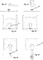
- Figures 12 to 19 show the different steps of positioning the case, securing and using the embedded anchor:
- Figures 20 to 25 show an embodiment of the invention for the insertion of the securing element in a floor S.
- This embodiment is characterised by a longer length of the hooks, which are slimmer, with a pointed distal end, and with an arched hook surface.
Landscapes
- Engineering & Computer Science (AREA)
- General Engineering & Computer Science (AREA)
- Mechanical Engineering (AREA)
- Architecture (AREA)
- Civil Engineering (AREA)
- Structural Engineering (AREA)
- Hooks, Suction Cups, And Attachment By Adhesive Means (AREA)
- Piles And Underground Anchors (AREA)
- Joining Of Building Structures In Genera (AREA)
Claims (10)
- Élément de fixation (1) de type ciseau, comprenant deux crochets reliés de manière pivotante (2, 3) par un arbre rotatif (4), une partie distale étant définie dans chaque crochet (2, 3) d'un côté de l'arbre (4) et une partie proximale étant définie de l'autre côté de l'arbre (4), les parties distales étant destinées à être introduites dans un étui (5) encastré dans une structure (E), chaque partie distale étant pourvue d'une dent (21, 31) et chaque partie proximale étant pourvue d'une fente pénétrante (22, 23), dans lequel une configuration d'insertion (P1) est définie, dans lequel les crochets (2, 3) sont superposés et une configuration de fixation (P2) dans laquelle les dents (21, 31) sont dans une position plus écartée et les crochets (2, 3) font saillie pour être retenus dans une surface intérieure d'appui (51) du boîtier (5), les fentes (22, 32) étant agencées de sorte que dans la configuration d'insertion les extrémités des fentes (22, 32) les plus proches de l'arbre (4) se chevauchent et dans la configuration de fixation les extrémités des fentes (22, 32) les plus éloignées de l'arbre (4) se chevauchent, dans lequel l'élément de fixation (1) comprend une manille (6), la manille (6) étant pourvue d'un anneau (61) pour le support la charge, caractérisé en ce que ladite manille comprend en outre deux extrémités d'anneau (62, 63) et une clavette (64) supportée par les deux extrémités (62, 63) et introduite dans les fentes (22, 32), et en ce que les extrémités (41, 42) de l'arbre (4) font saillie latéralement et les extrémités d'anneau (62, 63) sont pourvues d'un logement (65) de forme complémentaire des extrémités (41, 42) de l'arbre (4), de sorte qu'en configuration d'introduction, chacune des extrémités (41, 42) de l'arbre (4) est introduite dans le logement (65).
- Elément selon la revendication 1, dans lequel les extrémités des fentes (22, 32) les plus éloignées de l'arbre (4) sont pourvues sur leur surface interne d'un élément frangible (7).
- Elément selon la revendication 2, dans lequel l'élément frangible (7) est une languette attachée à ses extrémités aux parois internes de l'extrémité de la fente (22, 32) ou une liaison en saillie disposée à l'extrémité de la fente (22, 32).
- Elément selon l'une quelconque des revendications précédentes, dans lequel l'anneau (61) de la manille (6) est disposé dans un plan oblique par rapport au plan général de l'élément de fixation (1), de sorte que les joints entre l'anneau (61) et les extrémités d'anneau (62, 63) sont réalisés sur un côté supérieur de la clavette (64) sur des côtés opposés de celle-ci.
- Elément selon l'une quelconque des revendications précédentes, qui est symétrique par rapport à sa direction longitudinale.
- Ensemble d'ancrage de sécurité encastré du type destiné à être fixé à une parois ou à un élément structurel (E) pour former un point de sécurité pour l'accrochage de lignes de vie, de harnais de sécurité, des éléments de levage ou de fixation de charges et en général pour le maintien en toute sécurité de tout type de charge, l'ensemble de fixation étant pourvu d'un élément de fixation (1) selon l'une quelconque des revendications 1 à 5, et d'un boîtier (5) encastré dans une structure (E), caractérisé en ce qu'il comprend un disque de positionnement (8), le disque de positionnement (8) étant pourvu de premiers moyens de liaison amovibles au côté intérieur du moule du coffrage de parois (E) et de seconds moyens de liaison amovibles au boîtier (5).
- Ensemble selon la revendication 6, dans lequel le boîtier (5) est allongé, sa section est rectangulaire, sa partie distale comprend au moins deux élargissements latéraux, sa partie proximale comprend une bouche externe complémentaire du disque de positionnement (8) et des troisièmes moyens de liaison amovible complémentaires des seconds moyens de liaison du disque de positionnement (8).
- Ensemble selon l'une quelconque des revendications 6 ou 7, dans lequel chacun des crochets comprend des dents (21) à différents niveaux, afin que différents niveaux de fixation soient définis.
- Ensemble selon la revendication 6 avec un élément de fixation étant selon la revendication 2, dans lequel l'élément frangible (7) a un capteur qui lui est associé, qui à son tour est relié à un émetteur de signal.
- Ensemble selon la revendication 9, dans lequel le capteur comprend une puce RFID.
Applications Claiming Priority (2)
| Application Number | Priority Date | Filing Date | Title |
|---|---|---|---|
| ES201630833A ES2651115B1 (es) | 2016-06-20 | 2016-06-20 | Elemento de anclaje y conjunto de anclaje provisto de éste. |
| PCT/ES2017/070446 WO2017220837A1 (fr) | 2016-06-20 | 2017-06-20 | Élément d'ancrage et ensemble d'ancrage le comprenant |
Publications (3)
| Publication Number | Publication Date |
|---|---|
| EP3719232A1 EP3719232A1 (fr) | 2020-10-07 |
| EP3719232A4 EP3719232A4 (fr) | 2021-10-13 |
| EP3719232B1 true EP3719232B1 (fr) | 2022-11-30 |
Family
ID=60783833
Family Applications (1)
| Application Number | Title | Priority Date | Filing Date |
|---|---|---|---|
| EP17814804.5A Active EP3719232B1 (fr) | 2016-06-20 | 2017-06-20 | Élément d'ancrage et ensemble d'ancrage le comprenant |
Country Status (6)
| Country | Link |
|---|---|
| US (1) | US10737913B2 (fr) |
| EP (1) | EP3719232B1 (fr) |
| CA (1) | CA3029101A1 (fr) |
| ES (1) | ES2651115B1 (fr) |
| MX (1) | MX2018016243A (fr) |
| WO (1) | WO2017220837A1 (fr) |
Families Citing this family (4)
| Publication number | Priority date | Publication date | Assignee | Title |
|---|---|---|---|---|
| DE202018003185U1 (de) * | 2018-07-10 | 2018-07-30 | Halfen Gmbh | Haltesystem, Betonfertigteil mit einem Halteteil eines Haltesystems, Halteteil und Befestigungselement für ein Haltesystem |
| CA189025S (en) * | 2019-01-30 | 2021-12-13 | Sayfa R&D Pty Ltd | Vertical fall arrest safety device |
| ES3031657T3 (en) * | 2019-10-09 | 2025-07-10 | Doka Gmbh | Anchor |
| WO2021189094A1 (fr) * | 2020-03-24 | 2021-09-30 | John Holland Group Pty Ltd | Dispositif d'accouplement mécanique |
Family Cites Families (22)
| Publication number | Priority date | Publication date | Assignee | Title |
|---|---|---|---|---|
| US1023148A (en) * | 1911-12-30 | 1912-04-16 | John Hartman | Gambrel. |
| US1367044A (en) * | 1920-01-03 | 1921-02-01 | Hausler John | Crane-hook |
| GB395835A (en) | 1932-05-04 | 1933-07-27 | James Henry Bennetts | An improved device for anchoring attachments to concrete and like surfaces |
| US2832633A (en) * | 1954-06-30 | 1958-04-29 | Richard E Compson | Lifting device for coiled material |
| GB1435689A (en) | 1972-02-01 | 1976-05-12 | Lecormex Ltd | Device for securing scaffolding to building constructions |
| JPS5429413Y2 (fr) * | 1974-10-18 | 1979-09-19 | ||
| JPS567719Y2 (fr) * | 1974-11-07 | 1981-02-20 | ||
| US4300382A (en) * | 1980-05-15 | 1981-11-17 | Meek James S | Automobile body dent puller |
| US4417713A (en) | 1980-10-28 | 1983-11-29 | Snowden Dennie C | Safety belt clamp apparatus |
| US4423610A (en) * | 1981-06-22 | 1984-01-03 | Gross National Products, Inc. | Shackle lock |
| US5103755A (en) | 1991-01-22 | 1992-04-14 | The Crosby Group, Inc. | Hoisting line fittings with working load limit indicia |
| AP840A (en) | 1995-12-04 | 2000-06-01 | Bellambie Mining And Industrial Ltd | Safety detaching hooks. |
| FR2752232A1 (fr) | 1996-08-08 | 1998-02-13 | Batiment Et De Construction Cb | Dispositif pour accrocher un fardeau a une grue ou similaire |
| DE20317251U1 (de) | 2003-11-06 | 2004-03-18 | Klaus Fischer Gmbh | Personen-Abstürzsicherung bei Hoch- und Tiefbau-Anwendungen |
| US7669905B1 (en) * | 2007-07-10 | 2010-03-02 | Honda Motor Co., Ltd. | Rear suspension carrier device and method of use thereof |
| US8201865B2 (en) * | 2009-02-09 | 2012-06-19 | Hoopman Timothy L | Pipe gripper device for pulling pipe and methods of use |
| US20110175383A1 (en) | 2010-01-21 | 2011-07-21 | Segura Victor J | Shackle apparatus |
| US8171715B2 (en) * | 2010-01-21 | 2012-05-08 | Useful Products, L.L.C. | Shackle apparatus |
| CN103097274B (zh) * | 2010-07-26 | 2015-04-08 | 贾思特私人有限公司 | 接合总成 |
| BRPI1101479B1 (pt) * | 2011-04-19 | 2018-02-06 | Subsea 7 Do Brasil Serviços Ltda. | Dispositivo pivotável de conexão tripla de tamanho ajustável |
| ES2394246B1 (es) * | 2011-05-16 | 2013-12-03 | Juan Casas Alvarez | Anclaje empotrable de seguridad. |
| US8562048B2 (en) * | 2011-10-06 | 2013-10-22 | Reel Lift, Llc | Reel lifting device and method |
-
2016
- 2016-06-20 ES ES201630833A patent/ES2651115B1/es active Active
-
2017
- 2017-06-20 MX MX2018016243A patent/MX2018016243A/es unknown
- 2017-06-20 EP EP17814804.5A patent/EP3719232B1/fr active Active
- 2017-06-20 CA CA3029101A patent/CA3029101A1/fr active Pending
- 2017-06-20 US US16/312,243 patent/US10737913B2/en active Active
- 2017-06-20 WO PCT/ES2017/070446 patent/WO2017220837A1/fr not_active Ceased
Also Published As
| Publication number | Publication date |
|---|---|
| US10737913B2 (en) | 2020-08-11 |
| US20190233256A1 (en) | 2019-08-01 |
| CA3029101A1 (fr) | 2017-12-28 |
| EP3719232A1 (fr) | 2020-10-07 |
| ES2651115A1 (es) | 2018-01-24 |
| MX2018016243A (es) | 2019-08-29 |
| ES2651115B1 (es) | 2018-11-30 |
| EP3719232A4 (fr) | 2021-10-13 |
| WO2017220837A1 (fr) | 2017-12-28 |
Similar Documents
| Publication | Publication Date | Title |
|---|---|---|
| US10737913B2 (en) | Anchor assembly | |
| EP2743426A1 (fr) | Ancrage de sécurité encastrable | |
| US8453794B2 (en) | Anchor assembly | |
| CA2790694C (fr) | Systeme d'insertion de coquilles d'expansion a chambrage automatique | |
| US10112078B1 (en) | Step assembly with fall arrest capability including removable step | |
| US7793910B2 (en) | Surface-mounted post base | |
| KR20160131195A (ko) | 갱폼 하부케이지 고정용 브라켓 | |
| WO2013040585A2 (fr) | Dispositif à boulon d'ancrage et procédés de fonctionnement pour des structures résidentielles et commerciales | |
| US6142546A (en) | Ring clutch hoisting assembly | |
| EP1483466A1 (fr) | Appareil d'orientation | |
| EP3488116B1 (fr) | Ensemble d'ancrage rotatif | |
| US4877216A (en) | Automatically-releasable pipe-attachment device | |
| KR20170094822A (ko) | 가변형 앵커소켓이 구비된 하부 교량받침대 | |
| JP2005336897A (ja) | ボルト破断型緩衝ストッパー装置及び橋梁の免震装置 | |
| KR20140005923U (ko) | 파일 안전캡 | |
| KR102395145B1 (ko) | 매입형 앵커 | |
| KR101587908B1 (ko) | 인양 고리 장치 | |
| EP3081695B1 (fr) | Poteau de services publics avec ensemble de couplage à cisaillement | |
| EP0967347A1 (fr) | Méthode d'ancrage de sécurité, en particulier pour le levage de dalles en béton et élément de couplage pour sa mise en oeuvre | |
| KR101381992B1 (ko) | 대형거푸집의 본체볼트 다중 잠금장치 | |
| KR20210038262A (ko) | 갱폼 낙하 안전장치 | |
| KR101654163B1 (ko) | 인양용 체결구 | |
| KR200392136Y1 (ko) | 제거형 앵커 | |
| KR20210026079A (ko) | 갱폼 안전장치 | |
| CN213360147U (zh) | 锚索防坠落保护装置 |
Legal Events
| Date | Code | Title | Description |
|---|---|---|---|
| STAA | Information on the status of an ep patent application or granted ep patent |
Free format text: STATUS: THE INTERNATIONAL PUBLICATION HAS BEEN MADE |
|
| STAA | Information on the status of an ep patent application or granted ep patent |
Free format text: STATUS: THE APPLICATION IS DEEMED TO BE WITHDRAWN |
|
| STAA | Information on the status of an ep patent application or granted ep patent |
Free format text: STATUS: THE INTERNATIONAL PUBLICATION HAS BEEN MADE |
|
| PUAI | Public reference made under article 153(3) epc to a published international application that has entered the european phase |
Free format text: ORIGINAL CODE: 0009012 |
|
| STAA | Information on the status of an ep patent application or granted ep patent |
Free format text: STATUS: REQUEST FOR EXAMINATION WAS MADE |
|
| 17P | Request for examination filed |
Effective date: 20190120 |
|
| AK | Designated contracting states |
Kind code of ref document: A1 Designated state(s): AL AT BE BG CH CY CZ DE DK EE ES FI FR GB GR HR HU IE IS IT LI LT LU LV MC MK MT NL NO PL PT RO RS SE SI SK SM TR |
|
| A4 | Supplementary search report drawn up and despatched |
Effective date: 20210909 |
|
| RIC1 | Information provided on ipc code assigned before grant |
Ipc: F16B 13/00 20060101ALI20210903BHEP Ipc: F16B 13/08 20060101ALI20210903BHEP Ipc: F16B 2/04 20060101ALI20210903BHEP Ipc: E04G 21/32 20060101ALI20210903BHEP Ipc: F16B 41/00 20060101ALI20210903BHEP Ipc: F16B 45/00 20060101ALI20210903BHEP Ipc: B66C 1/66 20060101ALI20210903BHEP Ipc: E04G 5/04 20060101AFI20210903BHEP |
|
| GRAP | Despatch of communication of intention to grant a patent |
Free format text: ORIGINAL CODE: EPIDOSNIGR1 |
|
| STAA | Information on the status of an ep patent application or granted ep patent |
Free format text: STATUS: GRANT OF PATENT IS INTENDED |
|
| INTG | Intention to grant announced |
Effective date: 20220412 |
|
| INTG | Intention to grant announced |
Effective date: 20220610 |
|
| PUAJ | Public notification under rule 129 epc |
Free format text: ORIGINAL CODE: 0009425 |
|
| 32PN | Public notification |
Free format text: COMMUNICATION PURSUANT TO RULE 71(3) EPC (EPO FORM 2004 DATED 27/05/2022.) |
|
| GRAS | Grant fee paid |
Free format text: ORIGINAL CODE: EPIDOSNIGR3 |
|
| GRAA | (expected) grant |
Free format text: ORIGINAL CODE: 0009210 |
|
| STAA | Information on the status of an ep patent application or granted ep patent |
Free format text: STATUS: THE PATENT HAS BEEN GRANTED |
|
| AK | Designated contracting states |
Kind code of ref document: B1 Designated state(s): AL AT BE BG CH CY CZ DE DK EE ES FI FR GB GR HR HU IE IS IT LI LT LU LV MC MK MT NL NO PL PT RO RS SE SI SK SM TR |
|
| REG | Reference to a national code |
Ref country code: CH Ref legal event code: EP Ref country code: GB Ref legal event code: FG4D |
|
| REG | Reference to a national code |
Ref country code: AT Ref legal event code: REF Ref document number: 1534799 Country of ref document: AT Kind code of ref document: T Effective date: 20221215 Ref country code: DE Ref legal event code: R096 Ref document number: 602017064181 Country of ref document: DE |
|
| REG | Reference to a national code |
Ref country code: IE Ref legal event code: FG4D |
|
| REG | Reference to a national code |
Ref country code: LT Ref legal event code: MG9D |
|
| REG | Reference to a national code |
Ref country code: NL Ref legal event code: MP Effective date: 20221130 |
|
| PG25 | Lapsed in a contracting state [announced via postgrant information from national office to epo] |
Ref country code: SE Free format text: LAPSE BECAUSE OF FAILURE TO SUBMIT A TRANSLATION OF THE DESCRIPTION OR TO PAY THE FEE WITHIN THE PRESCRIBED TIME-LIMIT Effective date: 20221130 Ref country code: PT Free format text: LAPSE BECAUSE OF FAILURE TO SUBMIT A TRANSLATION OF THE DESCRIPTION OR TO PAY THE FEE WITHIN THE PRESCRIBED TIME-LIMIT Effective date: 20230331 Ref country code: NO Free format text: LAPSE BECAUSE OF FAILURE TO SUBMIT A TRANSLATION OF THE DESCRIPTION OR TO PAY THE FEE WITHIN THE PRESCRIBED TIME-LIMIT Effective date: 20230228 Ref country code: LT Free format text: LAPSE BECAUSE OF FAILURE TO SUBMIT A TRANSLATION OF THE DESCRIPTION OR TO PAY THE FEE WITHIN THE PRESCRIBED TIME-LIMIT Effective date: 20221130 Ref country code: FI Free format text: LAPSE BECAUSE OF FAILURE TO SUBMIT A TRANSLATION OF THE DESCRIPTION OR TO PAY THE FEE WITHIN THE PRESCRIBED TIME-LIMIT Effective date: 20221130 Ref country code: ES Free format text: LAPSE BECAUSE OF FAILURE TO SUBMIT A TRANSLATION OF THE DESCRIPTION OR TO PAY THE FEE WITHIN THE PRESCRIBED TIME-LIMIT Effective date: 20221130 |
|
| REG | Reference to a national code |
Ref country code: AT Ref legal event code: MK05 Ref document number: 1534799 Country of ref document: AT Kind code of ref document: T Effective date: 20221130 |
|
| PG25 | Lapsed in a contracting state [announced via postgrant information from national office to epo] |
Ref country code: RS Free format text: LAPSE BECAUSE OF FAILURE TO SUBMIT A TRANSLATION OF THE DESCRIPTION OR TO PAY THE FEE WITHIN THE PRESCRIBED TIME-LIMIT Effective date: 20221130 Ref country code: PL Free format text: LAPSE BECAUSE OF FAILURE TO SUBMIT A TRANSLATION OF THE DESCRIPTION OR TO PAY THE FEE WITHIN THE PRESCRIBED TIME-LIMIT Effective date: 20221130 Ref country code: LV Free format text: LAPSE BECAUSE OF FAILURE TO SUBMIT A TRANSLATION OF THE DESCRIPTION OR TO PAY THE FEE WITHIN THE PRESCRIBED TIME-LIMIT Effective date: 20221130 Ref country code: IS Free format text: LAPSE BECAUSE OF FAILURE TO SUBMIT A TRANSLATION OF THE DESCRIPTION OR TO PAY THE FEE WITHIN THE PRESCRIBED TIME-LIMIT Effective date: 20230330 Ref country code: HR Free format text: LAPSE BECAUSE OF FAILURE TO SUBMIT A TRANSLATION OF THE DESCRIPTION OR TO PAY THE FEE WITHIN THE PRESCRIBED TIME-LIMIT Effective date: 20221130 Ref country code: GR Free format text: LAPSE BECAUSE OF FAILURE TO SUBMIT A TRANSLATION OF THE DESCRIPTION OR TO PAY THE FEE WITHIN THE PRESCRIBED TIME-LIMIT Effective date: 20230301 |
|
| PG25 | Lapsed in a contracting state [announced via postgrant information from national office to epo] |
Ref country code: NL Free format text: LAPSE BECAUSE OF FAILURE TO SUBMIT A TRANSLATION OF THE DESCRIPTION OR TO PAY THE FEE WITHIN THE PRESCRIBED TIME-LIMIT Effective date: 20221130 |
|
| PG25 | Lapsed in a contracting state [announced via postgrant information from national office to epo] |
Ref country code: SM Free format text: LAPSE BECAUSE OF FAILURE TO SUBMIT A TRANSLATION OF THE DESCRIPTION OR TO PAY THE FEE WITHIN THE PRESCRIBED TIME-LIMIT Effective date: 20221130 Ref country code: RO Free format text: LAPSE BECAUSE OF FAILURE TO SUBMIT A TRANSLATION OF THE DESCRIPTION OR TO PAY THE FEE WITHIN THE PRESCRIBED TIME-LIMIT Effective date: 20221130 Ref country code: EE Free format text: LAPSE BECAUSE OF FAILURE TO SUBMIT A TRANSLATION OF THE DESCRIPTION OR TO PAY THE FEE WITHIN THE PRESCRIBED TIME-LIMIT Effective date: 20221130 Ref country code: DK Free format text: LAPSE BECAUSE OF FAILURE TO SUBMIT A TRANSLATION OF THE DESCRIPTION OR TO PAY THE FEE WITHIN THE PRESCRIBED TIME-LIMIT Effective date: 20221130 Ref country code: CZ Free format text: LAPSE BECAUSE OF FAILURE TO SUBMIT A TRANSLATION OF THE DESCRIPTION OR TO PAY THE FEE WITHIN THE PRESCRIBED TIME-LIMIT Effective date: 20221130 Ref country code: AT Free format text: LAPSE BECAUSE OF FAILURE TO SUBMIT A TRANSLATION OF THE DESCRIPTION OR TO PAY THE FEE WITHIN THE PRESCRIBED TIME-LIMIT Effective date: 20221130 |
|
| PG25 | Lapsed in a contracting state [announced via postgrant information from national office to epo] |
Ref country code: SK Free format text: LAPSE BECAUSE OF FAILURE TO SUBMIT A TRANSLATION OF THE DESCRIPTION OR TO PAY THE FEE WITHIN THE PRESCRIBED TIME-LIMIT Effective date: 20221130 Ref country code: AL Free format text: LAPSE BECAUSE OF FAILURE TO SUBMIT A TRANSLATION OF THE DESCRIPTION OR TO PAY THE FEE WITHIN THE PRESCRIBED TIME-LIMIT Effective date: 20221130 |
|
| REG | Reference to a national code |
Ref country code: DE Ref legal event code: R097 Ref document number: 602017064181 Country of ref document: DE |
|
| PLBE | No opposition filed within time limit |
Free format text: ORIGINAL CODE: 0009261 |
|
| STAA | Information on the status of an ep patent application or granted ep patent |
Free format text: STATUS: NO OPPOSITION FILED WITHIN TIME LIMIT |
|
| 26N | No opposition filed |
Effective date: 20230831 |
|
| PG25 | Lapsed in a contracting state [announced via postgrant information from national office to epo] |
Ref country code: SI Free format text: LAPSE BECAUSE OF FAILURE TO SUBMIT A TRANSLATION OF THE DESCRIPTION OR TO PAY THE FEE WITHIN THE PRESCRIBED TIME-LIMIT Effective date: 20221130 |
|
| PG25 | Lapsed in a contracting state [announced via postgrant information from national office to epo] |
Ref country code: MC Free format text: LAPSE BECAUSE OF FAILURE TO SUBMIT A TRANSLATION OF THE DESCRIPTION OR TO PAY THE FEE WITHIN THE PRESCRIBED TIME-LIMIT Effective date: 20221130 |
|
| PG25 | Lapsed in a contracting state [announced via postgrant information from national office to epo] |
Ref country code: MC Free format text: LAPSE BECAUSE OF FAILURE TO SUBMIT A TRANSLATION OF THE DESCRIPTION OR TO PAY THE FEE WITHIN THE PRESCRIBED TIME-LIMIT Effective date: 20221130 |
|
| REG | Reference to a national code |
Ref country code: CH Ref legal event code: PL |
|
| REG | Reference to a national code |
Ref country code: BE Ref legal event code: MM Effective date: 20230630 |
|
| PG25 | Lapsed in a contracting state [announced via postgrant information from national office to epo] |
Ref country code: LU Free format text: LAPSE BECAUSE OF NON-PAYMENT OF DUE FEES Effective date: 20230620 |
|
| REG | Reference to a national code |
Ref country code: IE Ref legal event code: MM4A |
|
| PG25 | Lapsed in a contracting state [announced via postgrant information from national office to epo] |
Ref country code: LU Free format text: LAPSE BECAUSE OF NON-PAYMENT OF DUE FEES Effective date: 20230620 |
|
| PG25 | Lapsed in a contracting state [announced via postgrant information from national office to epo] |
Ref country code: IE Free format text: LAPSE BECAUSE OF NON-PAYMENT OF DUE FEES Effective date: 20230620 |
|
| PG25 | Lapsed in a contracting state [announced via postgrant information from national office to epo] |
Ref country code: IE Free format text: LAPSE BECAUSE OF NON-PAYMENT OF DUE FEES Effective date: 20230620 Ref country code: CH Free format text: LAPSE BECAUSE OF NON-PAYMENT OF DUE FEES Effective date: 20230630 |
|
| PG25 | Lapsed in a contracting state [announced via postgrant information from national office to epo] |
Ref country code: IT Free format text: LAPSE BECAUSE OF FAILURE TO SUBMIT A TRANSLATION OF THE DESCRIPTION OR TO PAY THE FEE WITHIN THE PRESCRIBED TIME-LIMIT Effective date: 20221130 Ref country code: FR Free format text: LAPSE BECAUSE OF NON-PAYMENT OF DUE FEES Effective date: 20230630 Ref country code: BE Free format text: LAPSE BECAUSE OF NON-PAYMENT OF DUE FEES Effective date: 20230630 |
|
| PG25 | Lapsed in a contracting state [announced via postgrant information from national office to epo] |
Ref country code: BG Free format text: LAPSE BECAUSE OF FAILURE TO SUBMIT A TRANSLATION OF THE DESCRIPTION OR TO PAY THE FEE WITHIN THE PRESCRIBED TIME-LIMIT Effective date: 20221130 |
|
| PG25 | Lapsed in a contracting state [announced via postgrant information from national office to epo] |
Ref country code: BG Free format text: LAPSE BECAUSE OF FAILURE TO SUBMIT A TRANSLATION OF THE DESCRIPTION OR TO PAY THE FEE WITHIN THE PRESCRIBED TIME-LIMIT Effective date: 20221130 |
|
| PGFP | Annual fee paid to national office [announced via postgrant information from national office to epo] |
Ref country code: DE Payment date: 20250625 Year of fee payment: 9 |
|
| PG25 | Lapsed in a contracting state [announced via postgrant information from national office to epo] |
Ref country code: CY Free format text: LAPSE BECAUSE OF FAILURE TO SUBMIT A TRANSLATION OF THE DESCRIPTION OR TO PAY THE FEE WITHIN THE PRESCRIBED TIME-LIMIT; INVALID AB INITIO Effective date: 20170620 |
|
| PG25 | Lapsed in a contracting state [announced via postgrant information from national office to epo] |
Ref country code: HU Free format text: LAPSE BECAUSE OF FAILURE TO SUBMIT A TRANSLATION OF THE DESCRIPTION OR TO PAY THE FEE WITHIN THE PRESCRIBED TIME-LIMIT; INVALID AB INITIO Effective date: 20170620 |
|
| PGFP | Annual fee paid to national office [announced via postgrant information from national office to epo] |
Ref country code: GB Payment date: 20250721 Year of fee payment: 9 |
|
| PG25 | Lapsed in a contracting state [announced via postgrant information from national office to epo] |
Ref country code: TR Free format text: LAPSE BECAUSE OF FAILURE TO SUBMIT A TRANSLATION OF THE DESCRIPTION OR TO PAY THE FEE WITHIN THE PRESCRIBED TIME-LIMIT Effective date: 20221130 |