EP3719280B1 - Conduit de mélangeur de flux pour un système de purge - Google Patents
Conduit de mélangeur de flux pour un système de purge Download PDFInfo
- Publication number
- EP3719280B1 EP3719280B1 EP19382243.4A EP19382243A EP3719280B1 EP 3719280 B1 EP3719280 B1 EP 3719280B1 EP 19382243 A EP19382243 A EP 19382243A EP 3719280 B1 EP3719280 B1 EP 3719280B1
- Authority
- EP
- European Patent Office
- Prior art keywords
- duct
- continuous
- continuous piece
- longitudinal axis
- section
- Prior art date
- Legal status (The legal status is an assumption and is not a legal conclusion. Google has not performed a legal analysis and makes no representation as to the accuracy of the status listed.)
- Active
Links
Images


Classifications
-
- F—MECHANICAL ENGINEERING; LIGHTING; HEATING; WEAPONS; BLASTING
- F16—ENGINEERING ELEMENTS AND UNITS; GENERAL MEASURES FOR PRODUCING AND MAINTAINING EFFECTIVE FUNCTIONING OF MACHINES OR INSTALLATIONS; THERMAL INSULATION IN GENERAL
- F16L—PIPES; JOINTS OR FITTINGS FOR PIPES; SUPPORTS FOR PIPES, CABLES OR PROTECTIVE TUBING; MEANS FOR THERMAL INSULATION IN GENERAL
- F16L9/00—Rigid pipes
- F16L9/02—Rigid pipes of metal
-
- F—MECHANICAL ENGINEERING; LIGHTING; HEATING; WEAPONS; BLASTING
- F28—HEAT EXCHANGE IN GENERAL
- F28F—DETAILS OF HEAT-EXCHANGE AND HEAT-TRANSFER APPARATUS, OF GENERAL APPLICATION
- F28F1/00—Tubular elements; Assemblies of tubular elements
- F28F1/10—Tubular elements and assemblies thereof with means for increasing heat-transfer area, e.g. with fins, with projections, with recesses
- F28F1/12—Tubular elements and assemblies thereof with means for increasing heat-transfer area, e.g. with fins, with projections, with recesses the means being only outside the tubular element
- F28F1/14—Tubular elements and assemblies thereof with means for increasing heat-transfer area, e.g. with fins, with projections, with recesses the means being only outside the tubular element and extending longitudinally
-
- F—MECHANICAL ENGINEERING; LIGHTING; HEATING; WEAPONS; BLASTING
- F02—COMBUSTION ENGINES; HOT-GAS OR COMBUSTION-PRODUCT ENGINE PLANTS
- F02C—GAS-TURBINE PLANTS; AIR INTAKES FOR JET-PROPULSION PLANTS; CONTROLLING FUEL SUPPLY IN AIR-BREATHING JET-PROPULSION PLANTS
- F02C7/00—Features, components parts, details or accessories, not provided for in, or of interest apart form groups F02C1/00 - F02C6/00; Air intakes for jet-propulsion plants
- F02C7/12—Cooling of plants
- F02C7/16—Cooling of plants characterised by cooling medium
- F02C7/18—Cooling of plants characterised by cooling medium the medium being gaseous, e.g. air
-
- B—PERFORMING OPERATIONS; TRANSPORTING
- B64—AIRCRAFT; AVIATION; COSMONAUTICS
- B64D—EQUIPMENT FOR FITTING IN OR TO AIRCRAFT; FLIGHT SUITS; PARACHUTES; ARRANGEMENT OR MOUNTING OF POWER PLANTS OR PROPULSION TRANSMISSIONS IN AIRCRAFT
- B64D33/00—Arrangement in aircraft of power plant parts or auxiliaries not otherwise provided for
- B64D33/08—Arrangement in aircraft of power plant parts or auxiliaries not otherwise provided for of power plant cooling systems
-
- F—MECHANICAL ENGINEERING; LIGHTING; HEATING; WEAPONS; BLASTING
- F02—COMBUSTION ENGINES; HOT-GAS OR COMBUSTION-PRODUCT ENGINE PLANTS
- F02C—GAS-TURBINE PLANTS; AIR INTAKES FOR JET-PROPULSION PLANTS; CONTROLLING FUEL SUPPLY IN AIR-BREATHING JET-PROPULSION PLANTS
- F02C7/00—Features, components parts, details or accessories, not provided for in, or of interest apart form groups F02C1/00 - F02C6/00; Air intakes for jet-propulsion plants
- F02C7/12—Cooling of plants
- F02C7/14—Cooling of plants of fluids in the plant, e.g. lubricant or fuel
-
- F—MECHANICAL ENGINEERING; LIGHTING; HEATING; WEAPONS; BLASTING
- F02—COMBUSTION ENGINES; HOT-GAS OR COMBUSTION-PRODUCT ENGINE PLANTS
- F02C—GAS-TURBINE PLANTS; AIR INTAKES FOR JET-PROPULSION PLANTS; CONTROLLING FUEL SUPPLY IN AIR-BREATHING JET-PROPULSION PLANTS
- F02C9/00—Controlling gas-turbine plants; Controlling fuel supply in air- breathing jet-propulsion plants
- F02C9/16—Control of working fluid flow
- F02C9/18—Control of working fluid flow by bleeding, bypassing or acting on variable working fluid interconnections between turbines or compressors or their stages
-
- F—MECHANICAL ENGINEERING; LIGHTING; HEATING; WEAPONS; BLASTING
- F15—FLUID-PRESSURE ACTUATORS; HYDRAULICS OR PNEUMATICS IN GENERAL
- F15D—FLUID DYNAMICS, i.e. METHODS OR MEANS FOR INFLUENCING THE FLOW OF GASES OR LIQUIDS
- F15D1/00—Influencing flow of fluids
- F15D1/02—Influencing flow of fluids in pipes or conduits
- F15D1/06—Influencing flow of fluids in pipes or conduits by influencing the boundary layer
-
- F—MECHANICAL ENGINEERING; LIGHTING; HEATING; WEAPONS; BLASTING
- F05—INDEXING SCHEMES RELATING TO ENGINES OR PUMPS IN VARIOUS SUBCLASSES OF CLASSES F01-F04
- F05D—INDEXING SCHEME FOR ASPECTS RELATING TO NON-POSITIVE-DISPLACEMENT MACHINES OR ENGINES, GAS-TURBINES OR JET-PROPULSION PLANTS
- F05D2220/00—Application
- F05D2220/30—Application in turbines
- F05D2220/32—Application in turbines in gas turbines
- F05D2220/323—Application in turbines in gas turbines for aircraft propulsion, e.g. jet engines
-
- F—MECHANICAL ENGINEERING; LIGHTING; HEATING; WEAPONS; BLASTING
- F05—INDEXING SCHEMES RELATING TO ENGINES OR PUMPS IN VARIOUS SUBCLASSES OF CLASSES F01-F04
- F05D—INDEXING SCHEME FOR ASPECTS RELATING TO NON-POSITIVE-DISPLACEMENT MACHINES OR ENGINES, GAS-TURBINES OR JET-PROPULSION PLANTS
- F05D2240/00—Components
- F05D2240/10—Stators
- F05D2240/12—Fluid guiding means, e.g. vanes
- F05D2240/126—Baffles or ribs
-
- F—MECHANICAL ENGINEERING; LIGHTING; HEATING; WEAPONS; BLASTING
- F05—INDEXING SCHEMES RELATING TO ENGINES OR PUMPS IN VARIOUS SUBCLASSES OF CLASSES F01-F04
- F05D—INDEXING SCHEME FOR ASPECTS RELATING TO NON-POSITIVE-DISPLACEMENT MACHINES OR ENGINES, GAS-TURBINES OR JET-PROPULSION PLANTS
- F05D2240/00—Components
- F05D2240/10—Stators
- F05D2240/12—Fluid guiding means, e.g. vanes
- F05D2240/127—Vortex generators, turbulators, or the like, for mixing
-
- F—MECHANICAL ENGINEERING; LIGHTING; HEATING; WEAPONS; BLASTING
- F05—INDEXING SCHEMES RELATING TO ENGINES OR PUMPS IN VARIOUS SUBCLASSES OF CLASSES F01-F04
- F05D—INDEXING SCHEME FOR ASPECTS RELATING TO NON-POSITIVE-DISPLACEMENT MACHINES OR ENGINES, GAS-TURBINES OR JET-PROPULSION PLANTS
- F05D2250/00—Geometry
- F05D2250/20—Three-dimensional
- F05D2250/25—Three-dimensional helical
-
- F—MECHANICAL ENGINEERING; LIGHTING; HEATING; WEAPONS; BLASTING
- F05—INDEXING SCHEMES RELATING TO ENGINES OR PUMPS IN VARIOUS SUBCLASSES OF CLASSES F01-F04
- F05D—INDEXING SCHEME FOR ASPECTS RELATING TO NON-POSITIVE-DISPLACEMENT MACHINES OR ENGINES, GAS-TURBINES OR JET-PROPULSION PLANTS
- F05D2260/00—Function
- F05D2260/20—Heat transfer, e.g. cooling
- F05D2260/213—Heat transfer, e.g. cooling by the provision of a heat exchanger within the cooling circuit
-
- F—MECHANICAL ENGINEERING; LIGHTING; HEATING; WEAPONS; BLASTING
- F05—INDEXING SCHEMES RELATING TO ENGINES OR PUMPS IN VARIOUS SUBCLASSES OF CLASSES F01-F04
- F05D—INDEXING SCHEME FOR ASPECTS RELATING TO NON-POSITIVE-DISPLACEMENT MACHINES OR ENGINES, GAS-TURBINES OR JET-PROPULSION PLANTS
- F05D2260/00—Function
- F05D2260/20—Heat transfer, e.g. cooling
- F05D2260/221—Improvement of heat transfer
- F05D2260/2212—Improvement of heat transfer by creating turbulence
-
- F—MECHANICAL ENGINEERING; LIGHTING; HEATING; WEAPONS; BLASTING
- F28—HEAT EXCHANGE IN GENERAL
- F28F—DETAILS OF HEAT-EXCHANGE AND HEAT-TRANSFER APPARATUS, OF GENERAL APPLICATION
- F28F2210/00—Heat exchange conduits
- F28F2210/10—Particular layout, e.g. for uniform temperature distribution
-
- Y—GENERAL TAGGING OF NEW TECHNOLOGICAL DEVELOPMENTS; GENERAL TAGGING OF CROSS-SECTIONAL TECHNOLOGIES SPANNING OVER SEVERAL SECTIONS OF THE IPC; TECHNICAL SUBJECTS COVERED BY FORMER USPC CROSS-REFERENCE ART COLLECTIONS [XRACs] AND DIGESTS
- Y02—TECHNOLOGIES OR APPLICATIONS FOR MITIGATION OR ADAPTATION AGAINST CLIMATE CHANGE
- Y02T—CLIMATE CHANGE MITIGATION TECHNOLOGIES RELATED TO TRANSPORTATION
- Y02T50/00—Aeronautics or air transport
- Y02T50/60—Efficient propulsion technologies, e.g. for aircraft
Definitions
- the present invention belongs to the field of air systems, and particularly, it belongs to the field of protecting ducts working under high temperature gradients in an aircraft.
- the invention provides a duct with an inner featured wall which promotes reducing the temperature of the warmest airflow closer to the inner wall rather than rapidly mix the airflow if such incoming airflow has high temperature gradient.
- this bleed air is at high temperature and high pressure, wherein typical values of temperature are comprised in the range 200-500°C when extracted from the engine, and in the range 200-250°C after regulation in a precooler, and typical values of pressure is 275 kPa.
- this bleed air is channeled from said compressor stages of the engine to various locations within the aircraft, by a network of ducts, valves and regulators. Consequently, such channeling means are adapted to withstand the high temperature and pressure of the bleed air.
- thermal exchangers are normally used in the pylons, which separately run hot bleed air from the engine, and ram air from outside.
- the high temperature difference between both sides of the thermal exchanger entails that the cooled bleed airflow exiting the hot side of the thermal exchanger and passing to the duct for channeling, has an inadequate temperature gradient.
- the temperature gradient of this exiting airflow ranges from around 400K in the coolest spot up to 650K in the hottest spot.
- Typical materials such as titanium have been used in zones where temperature stays below 530K approx., but this temperature gradient issue makes locally inviable the use of such materials.
- static mixing devices have also been attempted different in shape and arrangement from the propeller-shaped ones.
- other static mixing devices may be the arrangement of aerodynamic airfoils in the warmest sector of the airflow at the beginning of the duct to induce that the hot air be directed towards the cold sector and avoid thereby prompt contact of that hot air with the duct.
- these static mixing devices as explained may not try to completely mix the flow, but to lower down the warmest part thereof and initiate turbulence for a faster mixing downstream.
- Documents EP3401629A1 and EP3026384A2 disclose heat exchangers.
- Document EP3181820A1 discloses a gas turbine engine component with a baffle insert.
- the present invention provides a solution for the aforementioned problems, by a duct for a bleed system according to claim 1, a bleed system for an aircraft according to claim 12, and an aircraft according to claim 13.
- a duct for a bleed system according to claim 1 a bleed system for an aircraft according to claim 12, and an aircraft according to claim 13.
- preferred embodiments of the invention are defined.
- the invention provides a duct for a bleed system of an aircraft, wherein the duct extends at least partially along a longitudinal axis, the duct comprising:
- 'duct' can be understood as a duct itself or a portion thereof in the sense of a bodily tube or vessel for carrying fluids, preferably gases, of the type of a pipe, tube, or channel.
- the longitudinal axis is the longitudinal directrix of the duct.
- the tilting degree of each portion should be understood as the angle formed with the longitudinal axis of the duct.
- fluid flow with a temperature gradient enters into the duct by the inlet section.
- the inlet section receives the airflow with the temperature gradient, a cold and hot sector being defined thereon depending on the relative temperature of the incoming flow. Normally, each sector has a semi-area of the inlet section.
- the outlet section allows that the fluid flow exits the duct.
- the first end of the at least one continuous piece, placed adjacent to the inlet section is actually arranged adjacent to the cold sector of the inlet section, the at least one continuous piece slantly advancing along the longitudinal axis direction of the duct up to the second end close to the outlet section.
- a portion of the airflow is therefore deflected in such a manner that the temperature gradient at the outlet section is lower than at the inlet section.
- the continuous piece has a shape small enough compared with the transversal cross-section which attains only deflecting the incoming airflow rather than throttling it. Also, as it is placed along the duct surface (where the flow speed is reduced because of the boundary layer), the pressure loss is minimized.
- the duct according to the invention has lower pressure loss (i.e. better performance) compared to state-of-art mixing devices.
- the continuous piece arranged on the inner wall of the duct is both economic and simple to manufacture, since it does not rely on complex curvatures of blades or airfoils, and tight welds.
- the created vortex supports the complete flow mixing at shorter distance downstream.
- temperature sensors can be placed at reduced distance and the duct needs not to have an excessive length.
- the duct comprises at least two continuous pieces arranged on the internal wall of the duct.
- the duct comprises two continuous pieces symmetrically arranged on the internal wall of the duct relative to the middle plane crossing by the longitudinal axis from up to bottom of the duct (that is, the vertical middle plane), the first ends of said continuous pieces being separated a first predetermined distance, and the second ends of said continuous pieces being separated a second predetermined distance.
- the bottom end of the duct corresponds to the coldest end in the cold sector while the upper end corresponds to the warmest end in the hot sector.
- the continuous pieces extend from the cold zone of the duct towards the warmest zone, following the flow direction.
- the continuous pieces do not extend completely along the inner perimeter of the duct in order not to locally impinge the airflow.
- the created vortex is more effective recirculating the airflow.
- the cold air raised to the warmest zone of the duct protects the metal surface from high temperature in a shorter distance.
- the first predetermined distance is greater than the second predetermined distance.
- At least two of the continuous pieces are arranged on the internal face of the duct staggered relative to the longitudinal axis, each continuous piece starting at a different position of the longitudinal axis.
- the duct is substantially cylindrical at least along a portion of the duct.
- the at least one continuous piece has a helical shape on the internal face of the cylindrical duct.
- the first and third portions are less tilted in relation to the longitudinal axis than the second portion.
- the first and third portions are substantially parallel to the longitudinal axis of the duct.
- the continuous piece has substantially round connections between respective portions.
- the at least one continuous piece is a substantially elongated thin piece. That is, its thickness is much less than any of the other dimensions (width and height).
- the at least one continuous piece is angled different from 90° with respect to the inner wall of the duct. In an embodiment, the angle between the at least one continuous piece and the inner wall of the duct varies along its path.
- the at least continuous piece has a torsion along its path.
- This configuration advantageously entails a more effective energization of the vortex, which causes the hot air to be pushed away from the internal wall of the duct.
- the duct portion adjacent to the outlet section is made of titanium. That is, unlike state-of-art solutions which attempts to use Inconel material to protect from degradation, the duct according to the present invention still has the capacity to withstand such a high temperature even made of titanium close to the outlet section thereof.
- the rest of the duct may be made of Inconel, for instance.
- the appended subsequent duct may be made of titanium.
- a bleed system for an aircraft comprises:
- the heat exchanger separate cold and hot sides by fins and walls.
- the invention provides an aircraft which comprises the bleed system according to the second inventive aspect.
- Figures 1a-c show an embodiment of a duct for a bleed system of an aircraft according to the invention.
- the duct is shown in front, longitudinal section and rear view, respectively.
- the duct extends along a longitudinal axis (z-z'), shown in figure 1(b) in dotted line.
- the duct comprises:
- the duct is substantially cylindrical.
- the two continuous pieces (4, 5) are symmetrically arranged on the internal wall of the duct (1) relative to the axis (z-z').
- the first ends (4.1, 5.1) of the continuous pieces (4, 5) are separated a first predetermined distance (d1)
- the second ends (4.2, 5.2) of the continuous pieces (4, 5) are separated a second predetermined distance (d2), as visible in figure 1 (c) .
- the first predetermined distance (d1) is smaller than the second predetermined distance (d2).
- the first predetermined distance (d1) may be greater than or equal to the second predetermined distance (d2).
- Figure 1(a) schematically shows the temperature distribution in the duct (1) at a position upstream the continuous pieces (4, 5).
- a cold air section and a hot air section are clearly distinguished in the figure, where the cold air section occupies the lower portion of the duct and the hot air section occupies the upper portion of the duct.
- temperature gradient always has a zone, or end, with less temperature (that is, “cold” air), and an opposite zone, or end, with higher temperature (that is, “hot” air), where temperature in zones therebetween gradually varies from one to other value.
- the two symmetrical continuous pieces (4, 5) protruding from the internal wall of the duct (1) guide the bottom cold air towards the top portion of the duct (1) along the internal wall.
- the cold air guided to the top naturally drives the hot air towards the centre of the duct (1), and creates a vortex.
- the created vortex helps the complete flow mixing at a small distance downstream the continuous pieces (4, 5). This is schematically shown in figures 1(b) and 1(c) .
- FIGS 2 and 3 show an embodiment of a duct according to the invention in perspective views.
- part of the wall of the duct is not represented in order to appreciate the continuous pieces (4, 5) arranged inside the duct.
- the duct is substantially cylindrical, the continuous pieces (4, 5) are arranged symmetrically on the internal wall of the duct relative to the axis (z-z') and have a helical shape.
- the continuous pieces (4, 5) protruding from the internal wall of the duct may be either built-in or joined by welding.
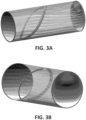
- Figures 3a-b show the results of CFD (Computational Fluid Dynamics) analysis performed for the duct according to the embodiment of figure 2 .
- the model was made for a duct having a diameter of 4.5 inch (114.3 cm) and 110 mm of maximum length.
- the temperature distributions at the inlet section (2) and at the outlet section (3) of the duct (1) are visible in figures 3(a) and 3(b) , respectively. It can be seen that the behaviour is as explained in connection with figure 1 , with the hot air being pushed away from the duct wall and the vortex starting to mix the airflow.
- Figures 4 and 5 show another embodiment of a duct according to the invention.
- This embodiment is a variant of the embodiment of figures 2 and 3 , wherein the difference with said embodiment is a greater distance between the first ends (4.1, 5.1) of the continuous pieces (4, 5).
- This widened distance between the first ends (4.1, 5.1) of the continuous pieces (4, 5) results in reduced effect and pressure loss, as visible in figure 5 , where the results of a CFD analysis performed for the duct according to the embodiment of figure 4 are shown.
- the CFD analysis performed for ducts according to the invention shows the ability to reduce a maximum upstream air temperature from 370°C to less than 290°C at the surface of the internal wall of the duct, with a pressure loss comparable to the one caused by deflector devices already used in the state of the art.
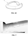
- Figures 6 and 7 show another embodiment of a duct (1) according to the invention.
- Figure 6(a) and 6(b) represent the duct (1) in front and longitudinal section views, respectively.
- figure 6(c) shows separately a continuous piece (4, 5) to be arranged inside this duct.
- each of the continuous pieces (4, 5) shown in figure 6 is formed by three portions:
- first (4.3, 5.3) and third (4.5, 5.5) portions have a different tilting in comparison with the second portion (4.4, 5.4), in regard of the angle formed with the longitudinal axis.
- both first (4.3, 5.3) and third (4.5, 5.5) portions are substantially parallel in respect to the longitudinal axis (z-z') of the duct (1).
- the second portion (4.4, 5.4) forms an angle between 30° and 60° with the longitudinal axis (z-z') of the duct (1).
- the angle formed with respect to the inner wall of by each section of the continuous piece (4, 5).
- the angle formed with the internal wall of the duct passes from an acute angle to obtuse along the path of the continuous piece.
- the continuous pieces (4, 6) have a torsion along their respective paths, wherein the torsion of each portion varies with respect to the others but keeping a smooth transition. Details of this can be seen in figure 6(a) .
- Figure 7 shows the results of CFD analysis performed for the duct (1) according to the embodiment of figure 5 with a model under the same conditions as explained in figures 2 and 3 .
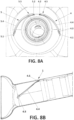
- FIG. 6 A variant of the embodiment of figures 6 and 7 is shown through figures 8 and 9 , wherein the difference with said embodiment is a greater distance between the first ends (4.1, 5.1) of the continuous pieces (4, 5).
- first (4.3, 5.3) and second (4.4, 5.4) portions are significantly less pronounced than corresponding portions of figure 6 , being indeed the first portion (4.3, 5.3) almost parallel to the longitudinal axis (z-z') of the duct (1).
- the continuous piece (4, 5) shown in figure 8(a) is angled (different from 90°) with respect to the inner wall of the duct differently for each of its sections. Nevertheless, smooth transitions between portions of a single continuous piece either in path, or in torsion takes place.
- Figure 9 shows the results of CFD analysis performed for the duct (1) according to the embodiment of figure 8 with a model under the same conditions as explained in figures 2 and 3 .
- Figure 10 shows an embodiment of an aircraft according to the invention.
- the aircraft comprises a bleed system (not shown) that comprises:
Landscapes
- Engineering & Computer Science (AREA)
- Combustion & Propulsion (AREA)
- Chemical & Material Sciences (AREA)
- Mechanical Engineering (AREA)
- General Engineering & Computer Science (AREA)
- Physics & Mathematics (AREA)
- Fluid Mechanics (AREA)
- Aviation & Aerospace Engineering (AREA)
- Geometry (AREA)
- Thermal Sciences (AREA)
- Duct Arrangements (AREA)
- Rigid Pipes And Flexible Pipes (AREA)
- Processing And Handling Of Plastics And Other Materials For Molding In General (AREA)
- Pipeline Systems (AREA)
Claims (13)
- Gaine (1) pour un système de prélèvement d'un aéronef, la gaine s'étendant au moins en partie suivant un axe longitudinal (z-z'), la gaine comprenant :- une section d'entrée (2) pour admettre un écoulement de fluide dans la gaine ;- une section de sortie (3) à distance de la section d'entrée (2), par laquelle cet écoulement de fluide sort de la gaine ; et- au moins une pièce continue (4, 5) agencée sur une paroi interne de la gaine et faisant saillie de celle-ci, l'au moins une pièce continue (4, 5) présentant :∘ une première extrémité (4.1, 5.1) occupant une position adjacente à la section d'entrée (2) et∘ une deuxième extrémité (4.2, 5.2) occupant une position proche de la section de sortie (3),la pièce continue (4, 5) s'étendant obliquement depuis la première extrémité (4.1, 5.1) jusqu'à la deuxième extrémité (4.2, 5.2) suivant la direction de l'axe longitudinal (z-z') de la gaine de sorte que les première et deuxième extrémités sont sensiblement opposées en section transversale de la gaine ;la gaine étant caractérisée en ce queau moins une pièce continue (4, 5) présente trois parties :- une première partie (4.3, 5.3) partant de la première extrémité (4.1, 5.1) de la pièce continue,- une deuxième partie (4.4, 5.4), et- une troisième partie (4.5, 5.5) finissant à la deuxième extrémité (4.2, 5.2) de la pièce continue,chaque partie (4.3, 5.3 ; 4.4, 5.4 ; 4.5, 5.5) de la pièce continue (4, 5) présentant un degré d'inclinaison différent par rapport à l'axe longitudinal (z-z') de la gaine (1) .
- Gaine selon la revendication 1, la gaine comprenant au moins deux pièces continues (4, 5) agencées sur la paroi interne de la gaine.
- Gaine selon la revendication 2, dans laquelle deux pièces continues (4, 5) sont agencées symétriquement sur la paroi interne de la gaine par rapport à un plan médian de haut en bas de la gaine (1) passant par l'axe longitudinal (z-z'), les premières extrémités (4.1, 5.1) desdites pièces continues étant séparées d'une première distance prédéterminée (d1) et les deuxièmes extrémités (4.2, 5.2) desdites pièces continues étant séparées d'une deuxième distance prédéterminée (d2).
- Gaine selon la revendication 3, dans laquelle la première distance prédéterminée (d1) est supérieure à la deuxième distance prédéterminée (d2).
- Gaine selon l'une quelconque des revendications 2 à 4, dans laquelle au moins deux des pièces continues (4, 5) sont agencées sur la face interne de la gaine en décalage par rapport à l'axe (z-z'), chaque pièce continue (4, 5) partant d'une position différente de l'axe longitudinal.
- Gaine selon l'une quelconque des revendications 1 à 5, la gaine étant sensiblement cylindrique au moins le long d'une partie de la gaine.
- Gaine selon l'une quelconque des revendications 1 à 6, dans laquelle les première (4.3, 5.3) et troisième (4.5, 5.5) parties sont moins inclinées par rapport à l'axe longitudinal (z-z') de la gaine que la deuxième partie (4.4, 5.4) .
- Gaine selon l'une quelconque des revendications 1 à 7, dans laquelle les première (4.3, 5.3) et troisième (4.5, 5.5) parties sont sensiblement parallèles à l'axe longitudinal (z-z') de la gaine, la deuxième partie (4.4, 5.4) formant de préférence un angle compris entre 30° et 60° avec l'axe longitudinal (z-z') de la gaine (1).
- Gaine selon l'une quelconque des revendications 1 à 8, dans laquelle l'au moins une pièce continue (4, 5) est une pièce mince sensiblement allongée.
- Gaine selon l'une quelconque des revendications 1 à 9, dans laquelle l'au moins une pièce continue (4, 5) forme un angle avec la paroi interne de la gaine.
- Gaine selon la revendication 10, dans laquelle l'angle entre l'au moins une pièce continue (4, 5) et la paroi interne de la gaine varie sur son trajet.
- Système de prélèvement d'un aéronef, comprenant :- un échangeur de chaleur présentant un côté froid et un côté chaud, le côté chaud comprenant une entrée et une sortie, et le côté froid comprenant une entrée et une sortie ; et- une gaine selon l'une quelconque des revendications 1 à 11 ;la sortie du côté chaud étant en communication fluidique avec la section d'entrée (2) de la gaine.
- Aéronef (10) comprenant le système de prélèvement selon la revendication 12.
Priority Applications (4)
| Application Number | Priority Date | Filing Date | Title |
|---|---|---|---|
| ES19382243T ES2944554T3 (es) | 2019-04-03 | 2019-04-03 | Conducto mezclador de flujo para un sistema de sangrado |
| EP19382243.4A EP3719280B1 (fr) | 2019-04-03 | 2019-04-03 | Conduit de mélangeur de flux pour un système de purge |
| US16/830,425 US11619456B2 (en) | 2019-04-03 | 2020-03-26 | Flow mixer duct for a bleed system |
| CN202010259535.6A CN111795216B (zh) | 2019-04-03 | 2020-04-03 | 用于排放系统的混流管道 |
Applications Claiming Priority (1)
| Application Number | Priority Date | Filing Date | Title |
|---|---|---|---|
| EP19382243.4A EP3719280B1 (fr) | 2019-04-03 | 2019-04-03 | Conduit de mélangeur de flux pour un système de purge |
Publications (2)
| Publication Number | Publication Date |
|---|---|
| EP3719280A1 EP3719280A1 (fr) | 2020-10-07 |
| EP3719280B1 true EP3719280B1 (fr) | 2023-03-01 |
Family
ID=66290364
Family Applications (1)
| Application Number | Title | Priority Date | Filing Date |
|---|---|---|---|
| EP19382243.4A Active EP3719280B1 (fr) | 2019-04-03 | 2019-04-03 | Conduit de mélangeur de flux pour un système de purge |
Country Status (4)
| Country | Link |
|---|---|
| US (1) | US11619456B2 (fr) |
| EP (1) | EP3719280B1 (fr) |
| CN (1) | CN111795216B (fr) |
| ES (1) | ES2944554T3 (fr) |
Citations (1)
| Publication number | Priority date | Publication date | Assignee | Title |
|---|---|---|---|---|
| FR3093540A1 (fr) * | 2019-03-07 | 2020-09-11 | Safran Aircraft Engines | Turbomachine double flux a gaz a bras echangeur thermique |
Family Cites Families (10)
| Publication number | Priority date | Publication date | Assignee | Title |
|---|---|---|---|---|
| US5581996A (en) * | 1995-08-16 | 1996-12-10 | General Electric Company | Method and apparatus for turbine cooling |
| FR2929334B1 (fr) * | 2008-03-31 | 2012-06-01 | Airbus France | Dispositif de reduction du bruit genere par reacteur d'aeronef a conduits de fluide coudes |
| US20160033059A1 (en) * | 2014-06-27 | 2016-02-04 | Ati Properties, Inc. | Flowforming corrosion resistant alloy tubes |
| GB201419963D0 (en) * | 2014-11-10 | 2014-12-24 | Rolls Royce Plc | Heat exchanger |
| US10280841B2 (en) * | 2015-12-07 | 2019-05-07 | United Technologies Corporation | Baffle insert for a gas turbine engine component and method of cooling |
| US10337334B2 (en) * | 2015-12-07 | 2019-07-02 | United Technologies Corporation | Gas turbine engine component with a baffle insert |
| ES2736527T3 (es) * | 2016-01-29 | 2020-01-02 | Airbus Operations Gmbh | Cuerpo de flujo para una aeronave para la aspiración de una capa límite pasiva |
| CN106439244A (zh) * | 2016-11-21 | 2017-02-22 | 无锡金顶石油管材配件制造有限公司 | 一种石油管道 |
| US10948108B2 (en) * | 2017-05-02 | 2021-03-16 | Unison Industries, Llc | Turbine engine duct |
| US20180328285A1 (en) * | 2017-05-11 | 2018-11-15 | Unison Industries, Llc | Heat exchanger |
-
2019
- 2019-04-03 EP EP19382243.4A patent/EP3719280B1/fr active Active
- 2019-04-03 ES ES19382243T patent/ES2944554T3/es active Active
-
2020
- 2020-03-26 US US16/830,425 patent/US11619456B2/en active Active
- 2020-04-03 CN CN202010259535.6A patent/CN111795216B/zh active Active
Patent Citations (1)
| Publication number | Priority date | Publication date | Assignee | Title |
|---|---|---|---|---|
| FR3093540A1 (fr) * | 2019-03-07 | 2020-09-11 | Safran Aircraft Engines | Turbomachine double flux a gaz a bras echangeur thermique |
Also Published As
| Publication number | Publication date |
|---|---|
| ES2944554T3 (es) | 2023-06-22 |
| US11619456B2 (en) | 2023-04-04 |
| CN111795216A (zh) | 2020-10-20 |
| EP3719280A1 (fr) | 2020-10-07 |
| US20200363142A1 (en) | 2020-11-19 |
| CN111795216B (zh) | 2024-04-12 |
Similar Documents
| Publication | Publication Date | Title |
|---|---|---|
| EP2803845B1 (fr) | Agencement d'échangeur de chaleur | |
| EP3553446B1 (fr) | Bord d'attaque profilé d'échangeur de chaleur à ailettes et plaque coulée | |
| EP2299058A2 (fr) | Aube rotorique ou statorique refroidie et conduite de fluide associée | |
| CN101487671A (zh) | 热交换器 | |
| EP3196582B1 (fr) | Échangeur de chaleur avec transfert de chaleur amélioré | |
| CN117516224A (zh) | 一种基于记忆合金的涡旋传热增强换热器及方法 | |
| CN101206099B (zh) | 车用热交换器 | |
| EP3719280B1 (fr) | Conduit de mélangeur de flux pour un système de purge | |
| EP4141370B1 (fr) | Forme fractale de noyau optimisée (addmfg) | |
| JP6678413B2 (ja) | 空気調和機 | |
| EP3800415B1 (fr) | Régulation passive de débit hexagonal | |
| EP3485213B1 (fr) | Échangeur de chaleur à entraînement | |
| US12516893B2 (en) | Heat exchangers with flow-modifying heat exchanger core tubes | |
| KR102726788B1 (ko) | 튜브-핀 어셈블리 | |
| EP4438875B1 (fr) | Prévention de l'écoulement inverse d'échappement de moteur | |
| CN112189080B (zh) | 飞行器发动机的热气管的、穿过发动机壁的出口 | |
| KR101927125B1 (ko) | 핀-튜브 열교환기 | |
| Ahmad et al. | Enhancement of heat transfer effectiveness of tabular air to air heat exchanger used in gas turbine engine–A CFD analysis of the problem | |
| US12292244B2 (en) | Additively manufactured heat exchanger layer | |
| EP3904810B1 (fr) | Échangeur de chaleur à ailettes et plaque de sous-congélation à débit transversal et à contre-débit | |
| CN120397274A (zh) | 飞行器用预冷换热器以及飞行器 | |
| US20180172270A1 (en) | Micro turbine generator with guide vane structure | |
| EP3219955B1 (fr) | Déflecteur de sortie d'un échangeur de chaleur | |
| CN120225830A (zh) | 一种用于热交换的设备、系统和方法 | |
| JP2026053104A (ja) | 熱交換器 |
Legal Events
| Date | Code | Title | Description |
|---|---|---|---|
| PUAI | Public reference made under article 153(3) epc to a published international application that has entered the european phase |
Free format text: ORIGINAL CODE: 0009012 |
|
| STAA | Information on the status of an ep patent application or granted ep patent |
Free format text: STATUS: THE APPLICATION HAS BEEN PUBLISHED |
|
| AK | Designated contracting states |
Kind code of ref document: A1 Designated state(s): AL AT BE BG CH CY CZ DE DK EE ES FI FR GB GR HR HU IE IS IT LI LT LU LV MC MK MT NL NO PL PT RO RS SE SI SK SM TR |
|
| AX | Request for extension of the european patent |
Extension state: BA ME |
|
| STAA | Information on the status of an ep patent application or granted ep patent |
Free format text: STATUS: REQUEST FOR EXAMINATION WAS MADE |
|
| 17P | Request for examination filed |
Effective date: 20210330 |
|
| RBV | Designated contracting states (corrected) |
Designated state(s): AL AT BE BG CH CY CZ DE DK EE ES FI FR GB GR HR HU IE IS IT LI LT LU LV MC MK MT NL NO PL PT RO RS SE SI SK SM TR |
|
| GRAP | Despatch of communication of intention to grant a patent |
Free format text: ORIGINAL CODE: EPIDOSNIGR1 |
|
| STAA | Information on the status of an ep patent application or granted ep patent |
Free format text: STATUS: GRANT OF PATENT IS INTENDED |
|
| INTG | Intention to grant announced |
Effective date: 20221202 |
|
| GRAS | Grant fee paid |
Free format text: ORIGINAL CODE: EPIDOSNIGR3 |
|
| GRAA | (expected) grant |
Free format text: ORIGINAL CODE: 0009210 |
|
| STAA | Information on the status of an ep patent application or granted ep patent |
Free format text: STATUS: THE PATENT HAS BEEN GRANTED |
|
| AK | Designated contracting states |
Kind code of ref document: B1 Designated state(s): AL AT BE BG CH CY CZ DE DK EE ES FI FR GB GR HR HU IE IS IT LI LT LU LV MC MK MT NL NO PL PT RO RS SE SI SK SM TR |
|
| REG | Reference to a national code |
Ref country code: GB Ref legal event code: FG4D |
|
| REG | Reference to a national code |
Ref country code: CH Ref legal event code: EP Ref country code: AT Ref legal event code: REF Ref document number: 1551118 Country of ref document: AT Kind code of ref document: T Effective date: 20230315 |
|
| REG | Reference to a national code |
Ref country code: DE Ref legal event code: R096 Ref document number: 602019025813 Country of ref document: DE |
|
| REG | Reference to a national code |
Ref country code: IE Ref legal event code: FG4D |
|
| REG | Reference to a national code |
Ref country code: ES Ref legal event code: FG2A Ref document number: 2944554 Country of ref document: ES Kind code of ref document: T3 Effective date: 20230622 |
|
| REG | Reference to a national code |
Ref country code: LT Ref legal event code: MG9D |
|
| REG | Reference to a national code |
Ref country code: NL Ref legal event code: MP Effective date: 20230301 |
|
| PG25 | Lapsed in a contracting state [announced via postgrant information from national office to epo] |
Ref country code: RS Free format text: LAPSE BECAUSE OF FAILURE TO SUBMIT A TRANSLATION OF THE DESCRIPTION OR TO PAY THE FEE WITHIN THE PRESCRIBED TIME-LIMIT Effective date: 20230301 Ref country code: NO Free format text: LAPSE BECAUSE OF FAILURE TO SUBMIT A TRANSLATION OF THE DESCRIPTION OR TO PAY THE FEE WITHIN THE PRESCRIBED TIME-LIMIT Effective date: 20230601 Ref country code: LV Free format text: LAPSE BECAUSE OF FAILURE TO SUBMIT A TRANSLATION OF THE DESCRIPTION OR TO PAY THE FEE WITHIN THE PRESCRIBED TIME-LIMIT Effective date: 20230301 Ref country code: LT Free format text: LAPSE BECAUSE OF FAILURE TO SUBMIT A TRANSLATION OF THE DESCRIPTION OR TO PAY THE FEE WITHIN THE PRESCRIBED TIME-LIMIT Effective date: 20230301 Ref country code: HR Free format text: LAPSE BECAUSE OF FAILURE TO SUBMIT A TRANSLATION OF THE DESCRIPTION OR TO PAY THE FEE WITHIN THE PRESCRIBED TIME-LIMIT Effective date: 20230301 |
|
| REG | Reference to a national code |
Ref country code: AT Ref legal event code: MK05 Ref document number: 1551118 Country of ref document: AT Kind code of ref document: T Effective date: 20230301 |
|
| PG25 | Lapsed in a contracting state [announced via postgrant information from national office to epo] |
Ref country code: SE Free format text: LAPSE BECAUSE OF FAILURE TO SUBMIT A TRANSLATION OF THE DESCRIPTION OR TO PAY THE FEE WITHIN THE PRESCRIBED TIME-LIMIT Effective date: 20230301 Ref country code: PL Free format text: LAPSE BECAUSE OF FAILURE TO SUBMIT A TRANSLATION OF THE DESCRIPTION OR TO PAY THE FEE WITHIN THE PRESCRIBED TIME-LIMIT Effective date: 20230301 Ref country code: NL Free format text: LAPSE BECAUSE OF FAILURE TO SUBMIT A TRANSLATION OF THE DESCRIPTION OR TO PAY THE FEE WITHIN THE PRESCRIBED TIME-LIMIT Effective date: 20230301 Ref country code: GR Free format text: LAPSE BECAUSE OF FAILURE TO SUBMIT A TRANSLATION OF THE DESCRIPTION OR TO PAY THE FEE WITHIN THE PRESCRIBED TIME-LIMIT Effective date: 20230602 Ref country code: FI Free format text: LAPSE BECAUSE OF FAILURE TO SUBMIT A TRANSLATION OF THE DESCRIPTION OR TO PAY THE FEE WITHIN THE PRESCRIBED TIME-LIMIT Effective date: 20230301 |
|
| PG25 | Lapsed in a contracting state [announced via postgrant information from national office to epo] |
Ref country code: SM Free format text: LAPSE BECAUSE OF FAILURE TO SUBMIT A TRANSLATION OF THE DESCRIPTION OR TO PAY THE FEE WITHIN THE PRESCRIBED TIME-LIMIT Effective date: 20230301 Ref country code: RO Free format text: LAPSE BECAUSE OF FAILURE TO SUBMIT A TRANSLATION OF THE DESCRIPTION OR TO PAY THE FEE WITHIN THE PRESCRIBED TIME-LIMIT Effective date: 20230301 Ref country code: PT Free format text: LAPSE BECAUSE OF FAILURE TO SUBMIT A TRANSLATION OF THE DESCRIPTION OR TO PAY THE FEE WITHIN THE PRESCRIBED TIME-LIMIT Effective date: 20230703 Ref country code: EE Free format text: LAPSE BECAUSE OF FAILURE TO SUBMIT A TRANSLATION OF THE DESCRIPTION OR TO PAY THE FEE WITHIN THE PRESCRIBED TIME-LIMIT Effective date: 20230301 Ref country code: CZ Free format text: LAPSE BECAUSE OF FAILURE TO SUBMIT A TRANSLATION OF THE DESCRIPTION OR TO PAY THE FEE WITHIN THE PRESCRIBED TIME-LIMIT Effective date: 20230301 Ref country code: AT Free format text: LAPSE BECAUSE OF FAILURE TO SUBMIT A TRANSLATION OF THE DESCRIPTION OR TO PAY THE FEE WITHIN THE PRESCRIBED TIME-LIMIT Effective date: 20230301 |
|
| PG25 | Lapsed in a contracting state [announced via postgrant information from national office to epo] |
Ref country code: SK Free format text: LAPSE BECAUSE OF FAILURE TO SUBMIT A TRANSLATION OF THE DESCRIPTION OR TO PAY THE FEE WITHIN THE PRESCRIBED TIME-LIMIT Effective date: 20230301 Ref country code: IS Free format text: LAPSE BECAUSE OF FAILURE TO SUBMIT A TRANSLATION OF THE DESCRIPTION OR TO PAY THE FEE WITHIN THE PRESCRIBED TIME-LIMIT Effective date: 20230701 |
|
| REG | Reference to a national code |
Ref country code: CH Ref legal event code: PL |
|
| REG | Reference to a national code |
Ref country code: DE Ref legal event code: R097 Ref document number: 602019025813 Country of ref document: DE |
|
| PG25 | Lapsed in a contracting state [announced via postgrant information from national office to epo] |
Ref country code: LU Free format text: LAPSE BECAUSE OF NON-PAYMENT OF DUE FEES Effective date: 20230403 |
|
| PLBE | No opposition filed within time limit |
Free format text: ORIGINAL CODE: 0009261 |
|
| STAA | Information on the status of an ep patent application or granted ep patent |
Free format text: STATUS: NO OPPOSITION FILED WITHIN TIME LIMIT |
|
| REG | Reference to a national code |
Ref country code: BE Ref legal event code: MM Effective date: 20230430 |
|
| PG25 | Lapsed in a contracting state [announced via postgrant information from national office to epo] |
Ref country code: MC Free format text: LAPSE BECAUSE OF FAILURE TO SUBMIT A TRANSLATION OF THE DESCRIPTION OR TO PAY THE FEE WITHIN THE PRESCRIBED TIME-LIMIT Effective date: 20230301 |
|
| PG25 | Lapsed in a contracting state [announced via postgrant information from national office to epo] |
Ref country code: SI Free format text: LAPSE BECAUSE OF FAILURE TO SUBMIT A TRANSLATION OF THE DESCRIPTION OR TO PAY THE FEE WITHIN THE PRESCRIBED TIME-LIMIT Effective date: 20230301 Ref country code: MC Free format text: LAPSE BECAUSE OF FAILURE TO SUBMIT A TRANSLATION OF THE DESCRIPTION OR TO PAY THE FEE WITHIN THE PRESCRIBED TIME-LIMIT Effective date: 20230301 Ref country code: LI Free format text: LAPSE BECAUSE OF NON-PAYMENT OF DUE FEES Effective date: 20230430 Ref country code: DK Free format text: LAPSE BECAUSE OF FAILURE TO SUBMIT A TRANSLATION OF THE DESCRIPTION OR TO PAY THE FEE WITHIN THE PRESCRIBED TIME-LIMIT Effective date: 20230301 Ref country code: CH Free format text: LAPSE BECAUSE OF NON-PAYMENT OF DUE FEES Effective date: 20230430 |
|
| 26N | No opposition filed |
Effective date: 20231204 |
|
| REG | Reference to a national code |
Ref country code: IE Ref legal event code: MM4A |
|
| PG25 | Lapsed in a contracting state [announced via postgrant information from national office to epo] |
Ref country code: BE Free format text: LAPSE BECAUSE OF NON-PAYMENT OF DUE FEES Effective date: 20230430 |
|
| PG25 | Lapsed in a contracting state [announced via postgrant information from national office to epo] |
Ref country code: IE Free format text: LAPSE BECAUSE OF NON-PAYMENT OF DUE FEES Effective date: 20230403 |
|
| PG25 | Lapsed in a contracting state [announced via postgrant information from national office to epo] |
Ref country code: IE Free format text: LAPSE BECAUSE OF NON-PAYMENT OF DUE FEES Effective date: 20230403 |
|
| PG25 | Lapsed in a contracting state [announced via postgrant information from national office to epo] |
Ref country code: IT Free format text: LAPSE BECAUSE OF FAILURE TO SUBMIT A TRANSLATION OF THE DESCRIPTION OR TO PAY THE FEE WITHIN THE PRESCRIBED TIME-LIMIT Effective date: 20230301 |
|
| PG25 | Lapsed in a contracting state [announced via postgrant information from national office to epo] |
Ref country code: BG Free format text: LAPSE BECAUSE OF FAILURE TO SUBMIT A TRANSLATION OF THE DESCRIPTION OR TO PAY THE FEE WITHIN THE PRESCRIBED TIME-LIMIT Effective date: 20230301 |
|
| PG25 | Lapsed in a contracting state [announced via postgrant information from national office to epo] |
Ref country code: BG Free format text: LAPSE BECAUSE OF FAILURE TO SUBMIT A TRANSLATION OF THE DESCRIPTION OR TO PAY THE FEE WITHIN THE PRESCRIBED TIME-LIMIT Effective date: 20230301 |
|
| PGFP | Annual fee paid to national office [announced via postgrant information from national office to epo] |
Ref country code: DE Payment date: 20250422 Year of fee payment: 7 |
|
| PGFP | Annual fee paid to national office [announced via postgrant information from national office to epo] |
Ref country code: GB Payment date: 20250423 Year of fee payment: 7 Ref country code: ES Payment date: 20250530 Year of fee payment: 7 |
|
| PGFP | Annual fee paid to national office [announced via postgrant information from national office to epo] |
Ref country code: FR Payment date: 20250425 Year of fee payment: 7 |
|
| PG25 | Lapsed in a contracting state [announced via postgrant information from national office to epo] |
Ref country code: CY Free format text: LAPSE BECAUSE OF FAILURE TO SUBMIT A TRANSLATION OF THE DESCRIPTION OR TO PAY THE FEE WITHIN THE PRESCRIBED TIME-LIMIT; INVALID AB INITIO Effective date: 20190403 |
|
| PG25 | Lapsed in a contracting state [announced via postgrant information from national office to epo] |
Ref country code: HU Free format text: LAPSE BECAUSE OF FAILURE TO SUBMIT A TRANSLATION OF THE DESCRIPTION OR TO PAY THE FEE WITHIN THE PRESCRIBED TIME-LIMIT; INVALID AB INITIO Effective date: 20190403 |
|
| PG25 | Lapsed in a contracting state [announced via postgrant information from national office to epo] |
Ref country code: TR Free format text: LAPSE BECAUSE OF FAILURE TO SUBMIT A TRANSLATION OF THE DESCRIPTION OR TO PAY THE FEE WITHIN THE PRESCRIBED TIME-LIMIT Effective date: 20230301 |