EP3719376A1 - Élément de connexion, ensemble de connexion et machine de réparation de pneu - Google Patents
Élément de connexion, ensemble de connexion et machine de réparation de pneu Download PDFInfo
- Publication number
- EP3719376A1 EP3719376A1 EP17933760.5A EP17933760A EP3719376A1 EP 3719376 A1 EP3719376 A1 EP 3719376A1 EP 17933760 A EP17933760 A EP 17933760A EP 3719376 A1 EP3719376 A1 EP 3719376A1
- Authority
- EP
- European Patent Office
- Prior art keywords
- connector
- hole
- end wall
- tire repairing
- interior cavity
- Prior art date
- Legal status (The legal status is an assumption and is not a legal conclusion. Google has not performed a legal analysis and makes no representation as to the accuracy of the status listed.)
- Pending
Links
Images


Classifications
-
- F—MECHANICAL ENGINEERING; LIGHTING; HEATING; WEAPONS; BLASTING
- F16—ENGINEERING ELEMENTS AND UNITS; GENERAL MEASURES FOR PRODUCING AND MAINTAINING EFFECTIVE FUNCTIONING OF MACHINES OR INSTALLATIONS; THERMAL INSULATION IN GENERAL
- F16L—PIPES; JOINTS OR FITTINGS FOR PIPES; SUPPORTS FOR PIPES, CABLES OR PROTECTIVE TUBING; MEANS FOR THERMAL INSULATION IN GENERAL
- F16L37/00—Couplings of the quick-acting type
- F16L37/24—Couplings of the quick-acting type in which the connection is made by inserting one member axially into the other and rotating it to a limited extent, e.g. with bayonet-action
- F16L37/244—Couplings of the quick-acting type in which the connection is made by inserting one member axially into the other and rotating it to a limited extent, e.g. with bayonet-action the coupling being co-axial with the pipe
- F16L37/252—Couplings of the quick-acting type in which the connection is made by inserting one member axially into the other and rotating it to a limited extent, e.g. with bayonet-action the coupling being co-axial with the pipe the male part having lugs on its periphery penetrating into the corresponding slots provided in the female part
-
- F—MECHANICAL ENGINEERING; LIGHTING; HEATING; WEAPONS; BLASTING
- F16—ENGINEERING ELEMENTS AND UNITS; GENERAL MEASURES FOR PRODUCING AND MAINTAINING EFFECTIVE FUNCTIONING OF MACHINES OR INSTALLATIONS; THERMAL INSULATION IN GENERAL
- F16L—PIPES; JOINTS OR FITTINGS FOR PIPES; SUPPORTS FOR PIPES, CABLES OR PROTECTIVE TUBING; MEANS FOR THERMAL INSULATION IN GENERAL
- F16L37/00—Couplings of the quick-acting type
- F16L37/08—Couplings of the quick-acting type in which the connection between abutting or axially overlapping ends is maintained by locking members
- F16L37/10—Couplings of the quick-acting type in which the connection between abutting or axially overlapping ends is maintained by locking members using a rotary external sleeve or ring on one part
- F16L37/107—Bayonet-type couplings
-
- B—PERFORMING OPERATIONS; TRANSPORTING
- B29—WORKING OF PLASTICS; WORKING OF SUBSTANCES IN A PLASTIC STATE IN GENERAL
- B29C—SHAPING OR JOINING OF PLASTICS; SHAPING OF MATERIAL IN A PLASTIC STATE, NOT OTHERWISE PROVIDED FOR; AFTER-TREATMENT OF THE SHAPED PRODUCTS, e.g. REPAIRING
- B29C73/00—Repairing of articles made from plastics or substances in a plastic state, e.g. of articles shaped or produced by using techniques covered by this subclass or subclass B29D
- B29C73/16—Auto-repairing or self-sealing arrangements or agents
- B29C73/166—Devices or methods for introducing sealing compositions into articles
-
- B—PERFORMING OPERATIONS; TRANSPORTING
- B60—VEHICLES IN GENERAL
- B60C—VEHICLE TYRES; TYRE INFLATION; TYRE CHANGING; CONNECTING VALVES TO INFLATABLE ELASTIC BODIES IN GENERAL; DEVICES OR ARRANGEMENTS RELATED TO TYRES
- B60C25/00—Apparatus or tools adapted for mounting, removing or inspecting tyres
-
- F—MECHANICAL ENGINEERING; LIGHTING; HEATING; WEAPONS; BLASTING
- F16—ENGINEERING ELEMENTS AND UNITS; GENERAL MEASURES FOR PRODUCING AND MAINTAINING EFFECTIVE FUNCTIONING OF MACHINES OR INSTALLATIONS; THERMAL INSULATION IN GENERAL
- F16L—PIPES; JOINTS OR FITTINGS FOR PIPES; SUPPORTS FOR PIPES, CABLES OR PROTECTIVE TUBING; MEANS FOR THERMAL INSULATION IN GENERAL
- F16L37/00—Couplings of the quick-acting type
- F16L37/08—Couplings of the quick-acting type in which the connection between abutting or axially overlapping ends is maintained by locking members
- F16L37/10—Couplings of the quick-acting type in which the connection between abutting or axially overlapping ends is maintained by locking members using a rotary external sleeve or ring on one part
- F16L37/113—Couplings of the quick-acting type in which the connection between abutting or axially overlapping ends is maintained by locking members using a rotary external sleeve or ring on one part the male part having lugs on its periphery penetrating into the corresponding slots provided in the female part
-
- B—PERFORMING OPERATIONS; TRANSPORTING
- B29—WORKING OF PLASTICS; WORKING OF SUBSTANCES IN A PLASTIC STATE IN GENERAL
- B29L—INDEXING SCHEME ASSOCIATED WITH SUBCLASS B29C, RELATING TO PARTICULAR ARTICLES
- B29L2030/00—Pneumatic or solid tyres or parts thereof
Definitions
- the invention relates to the technical field of mechanical connection; specifically, the present invention relates to connector and further relates to connecting assembly and tire repairing machine.
- a common sealing connection of parts such as a bolted connection, a flanged connection, etc., requires a longer transition to ensure a fit, resulting in the structure of the sealing connection itself occupying a longer longitudinal space, going against for the compactness of the structure; in addition, a large operation space is needed during disassembly, and disassembly in a small space cannot be realized.
- a first aspect of the present invention provides a connector, wherein the connector comprises: a circumferential side wall defining an interior cavity of the connector; a first end wall in which a first through hole is provided, the first through hole communicating the interior cavity with an exterior of the connector; a second end wall in which a second through hole is provided, the second through hole communicating the interior cavity with the exterior of the connector, wherein, the first through hole and the second through hole are both of a non-circular shape.
- the first through hole comprises a first round hole and a first guide slot on a periphery of the first round hole
- the second through hole comprises a second round hole and a second guide slot on the periphery of the first round hole.
- a first protrusion is provided at a distance from the first guide slot circumferentially on one side within the interior cavity of the first end wall, and/or a second protrusion is provided at a distance from the second guide slot circumferentially on one side within the interior cavity of the second end wall.
- the number of first guide slots is greater than one and the first guide slots are evenly distributed along the circumference of the first round hole, and/or the number of second guide slots is greater than one and the second guide slots are evenly distributed along the circumference of the second round hole.
- the first end wall has a first circumferential limit notch formed at the circumference of the first round hole
- the second end wall has a second circumferential limit notch formed at the circumference of the second round hole.
- a damping portion is formed on an outer periphery of the connector.
- a second aspect of the present invention provides a connecting assembly, wherein the connecting assembly comprises: the connector as described in the foregoing first aspect and a first connecting joint on a first component to be connected that conforms to a shape of the first through hole and a second connecting joint on the second component to be connected that conforms to the shape of the second through hole, the first connecting joint is adapted to enter the interior cavity through the first through hole, the second connecting joint is adapted to enter the interior cavity through the second through hole, and after the connector is rotated by a certain angle, within the interior cavity, the first connecting joint is engaged with the first end wall and the second connecting joint is engaged with the second end wall.
- a first open end of the first connecting joint sealingly reaches into a second open end of the second connecting joint.
- the first connecting joint includes a first cylindrical portion having the first open end and a first lug provided on the first cylindrical portion
- the second connecting joint has a second cylindrical portion including the second open end and a second lug provided on the second cylindrical portion.
- a first circumferential limiting protrusion is formed on the outer periphery of the first cylindrical portion and/or a second circumferential limiting protrusion is formed on the outer periphery of the second cylindrical portion.
- a third aspect of the present invention provides a tire repairing machine, wherein the tire repairing machine is provided with the connecting assembly as described in the foregoing second aspect.
- the tire repairing machine has a valve body, a tire repairing liquid connecting tube, and an air compressor connecting tube, the tire repairing liquid connecting tube and the air compressor connecting tube are connected to a dispensing nozzle of the tire repairing machine through the valve body, respectively, and a plug capable of sliding back and forth is provided in the valve body; the tire repairing liquid connecting tube and the valve body are connected by the connecting assembly therebetween, and the tire repairing liquid connecting tube and the valve body serve as the first component to be connected and the second component to be connected, respectively.
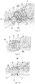
- FIG. 1 is a schematic perspective view of a connector according to one embodiment of the present invention.
- FIGS. 2 and 3 are, respectively, schematic end views of the two ends of the connector in FIG. 1 .
- FIG. 4 is a schematic side view of the connector in FIG. 1 .
- the connector 10 may have a circumferential side wall 11, a first end wall 12 and a second end wall 13.
- the first end wall 12 and the second end wall 13 may be provided at two end positions of the circumferential side wall 11, respectively.
- the first end wall 12 and the second end wall 13 are respectively connected or fixed to the circumferential side wall 11, e.g., assembled therewith, or integrally formed.
- the connector 10 may be made of a suitable material, such as plastic or metal, with appropriate thickness and stiffness depending on particular circumstances to meet the requirements of the connecting force.
- Circumferential holes (or hollow portions) 11a on the circumferential side wall 11 in the figure are process holes added for molding requirements or ease of processing, and may also be used for cutting by tools through reaching into the interior cavities, etc., simplifying the processing steps, which can advantageously reduce processing costs.
- Appropriate process hole shapes may be employed depending on the specific processing needs, which itself does not affect the use of the connector 10. It will be appreciated that the process holes may also be eliminated if allowed with the process level.
- the circumferential side wall 11 defines an interior cavity 14 of the connector 10.
- the inner and outer peripheral surfaces of the circumferential side wall 11 may be defined as circular cylindrical surfaces for ease of processing and operation, etc.
- the inner and outer peripheral surfaces of the circumferential side wall 11 may also be designed as cylindrical surfaces of other shapes according to specific needs of, such as space; or it is not limited to cylindrical designs, and may also be designed as tapered surfaces, or irregular surfaces, or the like.
- an axially extending, circumferentially distributed raised strips 15 along the connector 10 is distributed on the outer peripheral surface of the connector, being suitable for providing some damping when screwing the connector 10 by manual operation or tool operation, increasing resistance and avoiding slippage during operation, making the operation more reliable and enhancing the user experience.
- specific connecting and operating manner of the connector 10 it will be described in detail below in connection with FIGS. 8-10 .
- damping portions may be formed on the outer peripheral surface of the connector, these other types of damping portions are used to replace the raised strips 15.
- these raised strips may be designed to be curvilinear, or even modified to a notch, groove, concave or convex pattern, or the like.
- these other types of damping portions may be discrete point-like protrusions or recesses distributed on the outer peripheral surface of the connector. In additional embodiments, this can also be achieved by increasing the surface roughness of the outer peripheral surface of the connector.
- the connector 10 may have a first end wall 12.
- a first through hole 16 may be provided in the first end wall 12, the first through hole 16 communicates the interior cavity 14 with the exterior of the connector 10.
- the first through hole 16 may include a first round hole 16a and a first guide slot 16b on the periphery of the first round hole 16a.
- the number of first guide slot 16b may be provided as being greater than one and be evenly distributed along the circumference of the first round hole 16a.
- Two first guide slots 16b are shown in the illustrated example, and the two first guide slots 16b are distributed diametrically opposite along the first round hole 16a. It is understood that in other embodiments, if there are three, four, etc. first guide slots 16a, they may be evenly distributed every 120 degrees, 90 degrees, etc. circumferentially. A non-uniform distribution is also allowed.
- the first end wall 12 may also have a first circumferential limit notch 19a formed at the circumference of the first round hole 16a. It will be appreciated that, depending on the specific embodiment, the first circumferential limit notch 19a may not be provided, or a greater number of the first circumferential limit notches 19a may also be provided. The effects thereof are set forth below in conjunction with FIGS. 8-10 .
- the connector 10 may also have a second end wall 13.
- a second through hole 17 may be provided in the second end wall 13, the second through hole 17 communicates the interior cavity 14 with the exterior of the connector 10.
- the second through hole 17 includes a second round hole 17a and a second guide slot 17b on the periphery of the first round hole 17a.
- the number of second guide slot 17b may be provided as being greater than one and be evenly distributed along the circumference of the second round hole 17a.
- Two second guide slots 17b are shown in the illustrated example, and two second guide slots 17b are distributed diametrically opposite along the second round hole 17b. It is understood that in other embodiments, if there are three, four, etc. second guide slots 17b, they may be distributed every 120 degrees, 90 degrees, etc. circumferentially. A non-uniform distribution is also allowed.
- the shape, size, angular position of distribution, etc. of the second through hole 17 on the second end wall 13 is not necessarily the same as the shape, size, angular position of distribution, etc. of the first through hole 16 on the first end wall 12.
- the second end wall 13 may also have a second circumferential limit notch 19b formed at the circumference of the second round hole 17a. It will be appreciated that, depending on the specific embodiment, the second circumferential limit notch 19b may not be provided, or a greater number of the second circumferential limit notches 19b may also be provided. The bonding and working principle of the second circumferential limit notch 19b is similar to the first circumferential limit notch 19a.
- first through hole 16 and the second through hole 17 are not limited to the specific shape as shown in the figure.
- the axial connection function can be achieved as long as the first through hole 16 and the second through hole 17 are non-circular in shape.
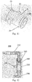
- FIG. 5 is a cross-sectional view taken along line A-A in FIG. 2 .
- FIG. 6 is a cross-sectional view taken along line B-B in FIG. 3 .
- FIG. 7 is a cross-sectional view taken along line C-C in FIG. 4 .
- the first end wall 12 may be provided with a first protrusion 18 at a distance from the first guide slot 16b circumferentially on one side within the interior cavity 14.
- the second end wall 13 may also be provided with a second protrusion (not illustrated) at a distance from the second guide slot 17b circumferentially on one side within the interior cavity 14.
- the thicknesses of the first end wall 12 and the second end wall 13 are not the same.
- the respective thicknesses of the first end wall 12, the second end wall 13, and the circumferential side wall 11 may be designed according to specific needs, for example taking into consideration various circumstances such as, but not limited to, connection strength, manufacturing material, installation space, and the like.
- One aspect of the invention also provides a connecting assembly comprising the connector of any of the foregoing embodiments.
- the connecting assembly may further include a first connecting joint on the first component to be connected (not illustrated) that conforms to the shape of the first through hole and a second connecting joint on the second component to be connected (not illustrated) that conforms to the shape of the second through hole.
- the shapes of the first and second through holes are adapted to be non-circular in shape such that the first connecting joint may be adapted to enter the interior cavity through the first through hole, the second connecting joint may be adapted to enter the interior cavity through the second through hole, and they engage the first end wall and the second end wall, respectively, within the interior cavity after the connector is rotated by an angle, thereby enabling a reliable axial connection between the first component to be connected and the second component to be connected.
- FIG. 8 is a schematic view of a connecting assembly according to one embodiment of the present invention, with the connecting assembly is in a disassembled state.
- FIG. 9 is a schematic view of the connecting assembly of FIG. 8 with the connecting assembly in a connected state.
- FIG. 10 is a cross-sectional view of the connecting assembly in FIG. 9 in a connected state.
- the connecting assembly 100 may include the connector 10 as in any of the foregoing embodiments.
- the connecting assembly 100 further includes a first connecting joint 20 on the first component to be connected (not illustrated) that conforms to the shape of the first through hole 16 of the connector 10 and a second connecting joint 30 on the second component to be connected (not illustrated) that conforms to the shape of the second through hole 17.
- FIGS. 8-10 is a connecting assembly in a tire repairing machine, wherein the first component to be connected is a tire repairing liquid connecting tube 210 in a tire repairing machine (see FIG. 12 ), and the second component to be connected is a valve body 220 in a tire repairing machine (see FIG. 12 ).
- the first connecting joint 20 may include a first cylindrical portion 21 having a first open end and a first lug 22 provided on the first cylindrical portion;
- the second connecting joint 30 may have a second cylindrical portion 31 including a second open end and a second lug 32 provided on the second cylindrical portion;
- a first circumferential limiting protrusion 23 may be formed on the outer periphery of the first cylindrical portion 21;
- a second circumferential limiting protrusion 33 may be formed on the outer periphery of the second cylindrical portion 31.
- first cylindrical portion 21 and the first lug 22 of the first connecting joint 20 conform to that of the first round hole 16a and the first guide slot 16b of the connector 10, respectively.
- first cylindrical portion 21 and the first lug 22 may be made through the first round hole 16a and the first guide slot 16b, after which the first lug 22 may be engaged within the interior cavity on the inside surface of the first end wall 12 after rotating the connector 10 by an angle, to realize an axial connection between the first connecting joint 20 and the connector 10.
- the connector 10 is rotated 90 degrees to enable a reliable connection.
- the shapes of the second cylindrical portion 31 and the second lug 32 of the second connecting joint 30 conform to that of the second round hole 17a and the second guide slot 17b of the connector 10, respectively.
- the second cylindrical portion 31 and the second lug 32 may be made through the second round hole 17a and the second guide slot 17b, after which the second lug 32 may be engaged within the interior cavity on the inside surface of the second end wall 13 after rotating the connecter 10 by an angle, to realize the connection between the second connecting joint 30 and the connector 10.
- first connecting joint 20 and the second connecting joint 30 may firstly reach into the connector 10, and then the connector 10 is rotated by an angle to achieve the connection.
- the first protrusion 18 inside the first end wall 12 is described above in connection with FIGS. 5 and 7 , and a second protrusion inside the second end wall 13 is mentioned.
- the first and second protrusions may define a circumferential engagement position of the connector relative to the first and second connecting joint by engaging the first and second lugs, respectively, enabling them to be effectively engaged with the first and second end walls of the connector 10.
- the first and second lugs will block the first and second protrusions when the connector is rotated to an appropriate circumferential position, thereby limiting further relative rotation of the connector relative to the first connecting joint and/or the second connecting joint, retaining it in the optimal connection position. It may be understood that regardless of the number of first and second lugs, only one first protrusion and/or only one second protrusion may be provided, and a good positioning effect can also be achieved.
- the first connecting joint 20 may have a first open end and the second connecting joint 30 may have a second open end.
- the first open end is located at the end of the first cylindrical portion 21 and the second open end is located at the end of the second cylindrical portion 31.
- FIG. 11 is a schematic view of one connecting joint in the connecting assembly of FIG. 8 .
- a ring of groove 24 may be provided on the outer circumference of the first cylindrical portion of the first connecting joint 20 near the distal end, and may be used to embed a seal ring 40 therein (see FIG. 10 ) to enable fluid sealing with the inner circumference of the second connecting joint 30, preventing media from leaking and ensuring reliable operation of the connection portion.
- a first circumferential limiting protrusion 23 and a second circumferential limiting protrusion 33 are provided on the outer peripheral sides of the first connecting joint 20 and the second connecting joint 30, respectively.
- the first connecting joint 20 When the first connecting joint 20 is connected to the connector 10, the first connecting joint 20 firstly reaches into the first through hole 16 of the connector 10, and then the connector 10 is rotated in a set direction, and when engaged in place, the first circumferential limiting protrusion 23 may be snapped slightly into the first circumferential limit notch 19a in the first round hole 16a of the first end wall 12, producing a in-place feeling as an indication of alignment.
- first circumferential limiting protrusion and the second circumferential limiting protrusion is adapted to be correspondent with the number and the circumferential distribution positions of first circumferential limit notches and the second circumferential limit notches, respectively.
- first connecting joint and the second connecting joint may also employ corresponding shapes to allow the first connecting joint and the second connecting joint to pass through the first through hole and the second through hole, and to form a reliable axial connection by engaging the joints with the insides of the first end wall and the second end wall after the connector is rotated by a certain angle.
- the connecting assembly when it is not used in a tire repairing machine, it may also be provided with respective features such as a first open end, a second open end, and the like, to be adapted to reliably deliver fluid.
- the tire repairing machine may be provided with the connecting assembly as described in any of the foregoing embodiments.
- the tire repairing machine may have a valve body, a tire repairing liquid connecting tube, and an air compressor connecting tube, the tire repairing liquid connecting tube and an air compressor connecting tube may be connected to the dispensing nozzle of the tire repairing machine through the valve body, respectively, and the tire repairing liquid connecting tube and the valve body may be connected by a connecting assembly therebetween.
- the tire repairing liquid connecting tube and the valve body may serve as a first component to be connected and a second component to be connected respectively. It can be seen that, such arrangement is for a dual purpose tire repairing machine that, through its dispensing nozzle, it can both dispense the tire repairing liquid to repair a tire and can also dispense air to inflate the tire.
- FIG. 12 shows a schematic view of the dispensing mechanism of the tire repairing machine of this embodiment.
- one end of the tire repairing liquid connecting tube 210 and one end of the air compressor connecting tube 230 are connected to the valve body 220, respectively.
- the other end of the tire repairing liquid connecting tube 210 may be connected to a tire repairing liquid vessel (not illustrated), and the other end of the air compressor connecting tube 230 may be connected to an air compressor (not illustrated).
- the valve body 220 may be provided therein with a plug 260 that is capable of sliding back and forth within the valve body 220, thereby enabling the switch of the valve body communication between the tire repairing liquid vessel and the air compressor.
- the plug 260 moves to the tire repairing liquid connecting tube 210, and the dispensing nozzle 250 is adapted to inflate the tire; when the pressure at the air compressor connecting tube 230 is smaller than the pressure at the tire repairing liquid connecting tube 210, the plug 260 moves to the air compressor connecting tube 230, and the dispensing nozzle 250 is adapted to dispense the tire repairing liquid to perform the tire repairing operation.
- connection between the tire repairing liquid connecting tube 210 and the valve body 220 advantageously employs the connecting assembly of the aforementioned embodiments of the present invention, with the connector 240 connected between the tire repairing liquid connecting tube 210 and the valve body 220.
- the sealing assembly and disassembly of the tire repairing liquid connecting tube and the valve body convenience is provided for assembly and disassembly in a small space of products such as the tire repairing machine.
- connectors and connecting assemblies in connection with the example of a tire repairing machine
- the connectors and connecting assemblies required with respect to the present application are not limited to being used in a tire repairing machine, but are applicable to any device requiring axial connection.
Landscapes
- Engineering & Computer Science (AREA)
- General Engineering & Computer Science (AREA)
- Mechanical Engineering (AREA)
- Quick-Acting Or Multi-Walled Pipe Joints (AREA)
Applications Claiming Priority (1)
| Application Number | Priority Date | Filing Date | Title |
|---|---|---|---|
| PCT/CN2017/113495 WO2019104512A1 (fr) | 2017-11-29 | 2017-11-29 | Élément de connexion, ensemble de connexion et machine de réparation de pneu |
Publications (2)
| Publication Number | Publication Date |
|---|---|
| EP3719376A1 true EP3719376A1 (fr) | 2020-10-07 |
| EP3719376A4 EP3719376A4 (fr) | 2021-07-21 |
Family
ID=66663742
Family Applications (1)
| Application Number | Title | Priority Date | Filing Date |
|---|---|---|---|
| EP17933760.5A Pending EP3719376A4 (fr) | 2017-11-29 | 2017-11-29 | Élément de connexion, ensemble de connexion et machine de réparation de pneu |
Country Status (5)
| Country | Link |
|---|---|
| US (1) | US11662046B2 (fr) |
| EP (1) | EP3719376A4 (fr) |
| JP (1) | JP7046183B2 (fr) |
| KR (1) | KR102405725B1 (fr) |
| WO (1) | WO2019104512A1 (fr) |
Families Citing this family (1)
| Publication number | Priority date | Publication date | Assignee | Title |
|---|---|---|---|---|
| DE102021124118A1 (de) * | 2021-09-17 | 2023-03-23 | Aircom Automotive Sp. z o.o. Sp. k. | Kompressor für eine Vorrichtung zum Abdichten von Luftreifen mittels einer Dichtflüssigkeit |
Family Cites Families (22)
| Publication number | Priority date | Publication date | Assignee | Title |
|---|---|---|---|---|
| US337867A (en) * | 1886-03-16 | Pipe-joint | ||
| US259501A (en) * | 1882-06-13 | Coupling for tubing | ||
| US1596645A (en) * | 1926-04-12 | 1926-08-17 | Edgar T Whatley | Detachable coupling |
| FR861123A (fr) | 1938-11-17 | 1941-02-01 | Goodrich Co B F | Perfectionnements aux joints pour tuyaux |
| NL98750C (fr) | 1954-10-20 | 1900-01-01 | ||
| JPS57144659U (fr) * | 1981-03-06 | 1982-09-10 | ||
| JPH01166195U (fr) * | 1988-01-28 | 1989-11-21 | ||
| JPH0230599U (fr) * | 1988-08-17 | 1990-02-27 | ||
| JP3423072B2 (ja) * | 1994-05-30 | 2003-07-07 | 三洋電機株式会社 | 飲料コンテナ用のホース接続具 |
| DE19625372B4 (de) * | 1996-06-25 | 2006-05-24 | Sumitomo Rubber Industries Ltd., Kobe | Verfahren zum Entfernen von Pannen-Abdichtmitteln aus Reifen und Vorrichtung zur Durchführung des Verfahrens |
| KR100291654B1 (ko) * | 1998-08-14 | 2001-07-12 | 이도연 | 배관이음용커플링 |
| ITTO20040121A1 (it) * | 2004-02-27 | 2004-05-27 | Tek Srl | Contenitore per un liquido sigillante per la riparazione di oggetti gonfiabili, in particolare pnematici, e kit di riparazione provvisto di tale contenitore |
| JP4437435B2 (ja) * | 2004-10-19 | 2010-03-24 | リンナイ株式会社 | 配管連結用金具 |
| JP2006117193A (ja) * | 2004-10-25 | 2006-05-11 | Bridgestone Corp | シーリング・ポンプアップ装置 |
| EP1726863B1 (fr) * | 2005-05-25 | 2010-03-03 | Erhard GmbH & Co. KG | Dispositif pour établir un raccord entre un embout métallique et un tuyau en plastique |
| DE102005049082A1 (de) * | 2005-10-13 | 2007-04-26 | Airbus Deutschland Gmbh | Paarung zweier Körper mit ineinander steckbaren rohr- oder hülsenförmigen Verbindungsabschnitten als Teil eines Klimatisierungsleitungssystems eines Flugzeugs |
| DE202006004407U1 (de) * | 2006-03-17 | 2007-07-19 | Mann+Hummel Gmbh | Anschluss für ein rohrförmiges Luftführungselement an einem Turbolader |
| CN203752543U (zh) * | 2013-11-22 | 2014-08-06 | 上海华汇机电有限公司 | 补胎液充气泵转换装置 |
| TWI596278B (zh) | 2016-02-04 | 2017-08-21 | 上森實業有限公司 | Air nozzle connector |
| JP6606807B2 (ja) * | 2017-03-08 | 2019-11-20 | Smc株式会社 | 軸連結構造及び流体圧装置 |
| CN106809187B (zh) | 2017-03-13 | 2023-03-21 | 大胜天成科技(惠州)有限公司 | 一种充气补胎一体机 |
| CN207539128U (zh) | 2017-11-29 | 2018-06-26 | 东莞冠翔电机有限公司 | 连接件、连接组件及补胎机 |
-
2017
- 2017-11-29 EP EP17933760.5A patent/EP3719376A4/fr active Pending
- 2017-11-29 KR KR1020207017365A patent/KR102405725B1/ko active Active
- 2017-11-29 JP JP2020529380A patent/JP7046183B2/ja active Active
- 2017-11-29 WO PCT/CN2017/113495 patent/WO2019104512A1/fr not_active Ceased
- 2017-11-29 US US16/767,696 patent/US11662046B2/en active Active
Also Published As
| Publication number | Publication date |
|---|---|
| JP7046183B2 (ja) | 2022-04-01 |
| US11662046B2 (en) | 2023-05-30 |
| WO2019104512A1 (fr) | 2019-06-06 |
| EP3719376A4 (fr) | 2021-07-21 |
| US20200355309A1 (en) | 2020-11-12 |
| JP2021504650A (ja) | 2021-02-15 |
| KR102405725B1 (ko) | 2022-06-07 |
| KR20200087233A (ko) | 2020-07-20 |
Similar Documents
| Publication | Publication Date | Title |
|---|---|---|
| KR101713477B1 (ko) | 곡관 | |
| CN207539128U (zh) | 连接件、连接组件及补胎机 | |
| CN107152575B (zh) | 一种同轴式自封接头 | |
| US9511380B2 (en) | Compressed air gun | |
| WO2018044771A1 (fr) | Éléments de mélange statiques empilables | |
| JP2006313010A (ja) | 配管継手装置 | |
| JP2009532642A (ja) | 成形工具のための膨らまし可能なシール装置 | |
| US5299347A (en) | Tool for removing and inserting a plumbing fixture seal structure | |
| US11662046B2 (en) | Connection member, connection assembly and tire repair machine | |
| KR20210107110A (ko) | 로터리 조인트 | |
| US6953195B2 (en) | Sealing device | |
| US20210346895A1 (en) | Nozzle assembly for delivering an oscillating spray pattern | |
| US20150014372A1 (en) | Nozzle Part, Connector, Nozzle Assembly, and Kit | |
| JP7152341B2 (ja) | 回転式切換弁 | |
| US20100187811A1 (en) | Rotatable coupling | |
| EP2357389B1 (fr) | Appareil de sertissage ayant une bague d'étanchéité | |
| CN219775132U (zh) | 转换接头和充气设备 | |
| US8414033B2 (en) | Pipe joint and pipe equipped with pipe joint | |
| CN109838431A (zh) | 连接件、连接组件及补胎机 | |
| US20150343616A1 (en) | Hammering set for an impact tool | |
| GB2587898A (en) | Water outlet device with joint nut | |
| CN216518528U (zh) | 一种卡扣式快捷转接气嘴 | |
| KR20170021077A (ko) | 유압 센터조인트 | |
| GB2512123A (en) | Nozzle | |
| KR200482815Y1 (ko) | 배관용 와셔플러그 |
Legal Events
| Date | Code | Title | Description |
|---|---|---|---|
| STAA | Information on the status of an ep patent application or granted ep patent |
Free format text: STATUS: THE INTERNATIONAL PUBLICATION HAS BEEN MADE |
|
| PUAI | Public reference made under article 153(3) epc to a published international application that has entered the european phase |
Free format text: ORIGINAL CODE: 0009012 |
|
| STAA | Information on the status of an ep patent application or granted ep patent |
Free format text: STATUS: REQUEST FOR EXAMINATION WAS MADE |
|
| 17P | Request for examination filed |
Effective date: 20200529 |
|
| AK | Designated contracting states |
Kind code of ref document: A1 Designated state(s): AL AT BE BG CH CY CZ DE DK EE ES FI FR GB GR HR HU IE IS IT LI LT LU LV MC MK MT NL NO PL PT RO RS SE SI SK SM TR |
|
| AX | Request for extension of the european patent |
Extension state: BA ME |
|
| DAV | Request for validation of the european patent (deleted) | ||
| DAX | Request for extension of the european patent (deleted) | ||
| A4 | Supplementary search report drawn up and despatched |
Effective date: 20210622 |
|
| RIC1 | Information provided on ipc code assigned before grant |
Ipc: F16L 37/252 20060101AFI20210616BHEP Ipc: F16L 37/107 20060101ALI20210616BHEP Ipc: F16L 37/113 20060101ALI20210616BHEP |
|
| STAA | Information on the status of an ep patent application or granted ep patent |
Free format text: STATUS: EXAMINATION IS IN PROGRESS |
|
| 17Q | First examination report despatched |
Effective date: 20230809 |