EP3719476B1 - Conduite comprenant dispositif de mesure permettant de détecter des particules et dispositif pour la transmission de dates depuis la conduite - Google Patents
Conduite comprenant dispositif de mesure permettant de détecter des particules et dispositif pour la transmission de dates depuis la conduite Download PDFInfo
- Publication number
- EP3719476B1 EP3719476B1 EP20167758.0A EP20167758A EP3719476B1 EP 3719476 B1 EP3719476 B1 EP 3719476B1 EP 20167758 A EP20167758 A EP 20167758A EP 3719476 B1 EP3719476 B1 EP 3719476B1
- Authority
- EP
- European Patent Office
- Prior art keywords
- detection unit
- pipeline
- particles
- unit
- designed
- Prior art date
- Legal status (The legal status is an assumption and is not a legal conclusion. Google has not performed a legal analysis and makes no representation as to the accuracy of the status listed.)
- Active
Links
Images
Classifications
-
- G—PHYSICS
- G01—MEASURING; TESTING
- G01N—INVESTIGATING OR ANALYSING MATERIALS BY DETERMINING THEIR CHEMICAL OR PHYSICAL PROPERTIES
- G01N15/00—Investigating characteristics of particles; Investigating permeability, pore-volume or surface-area of porous materials
- G01N15/06—Investigating concentration of particle suspensions
-
- G—PHYSICS
- G01—MEASURING; TESTING
- G01N—INVESTIGATING OR ANALYSING MATERIALS BY DETERMINING THEIR CHEMICAL OR PHYSICAL PROPERTIES
- G01N15/00—Investigating characteristics of particles; Investigating permeability, pore-volume or surface-area of porous materials
- G01N15/10—Investigating individual particles
- G01N15/14—Optical investigation techniques, e.g. flow cytometry
- G01N15/1429—Signal processing
- G01N15/1433—Signal processing using image recognition
-
- G—PHYSICS
- G01—MEASURING; TESTING
- G01N—INVESTIGATING OR ANALYSING MATERIALS BY DETERMINING THEIR CHEMICAL OR PHYSICAL PROPERTIES
- G01N15/00—Investigating characteristics of particles; Investigating permeability, pore-volume or surface-area of porous materials
- G01N15/10—Investigating individual particles
- G01N15/14—Optical investigation techniques, e.g. flow cytometry
- G01N15/1456—Optical investigation techniques, e.g. flow cytometry without spatial resolution of the texture or inner structure of the particle, e.g. processing of pulse signals
- G01N15/1459—Optical investigation techniques, e.g. flow cytometry without spatial resolution of the texture or inner structure of the particle, e.g. processing of pulse signals the analysis being performed on a sample stream
-
- G—PHYSICS
- G01—MEASURING; TESTING
- G01N—INVESTIGATING OR ANALYSING MATERIALS BY DETERMINING THEIR CHEMICAL OR PHYSICAL PROPERTIES
- G01N15/00—Investigating characteristics of particles; Investigating permeability, pore-volume or surface-area of porous materials
- G01N15/10—Investigating individual particles
- G01N15/14—Optical investigation techniques, e.g. flow cytometry
- G01N15/1468—Optical investigation techniques, e.g. flow cytometry with spatial resolution of the texture or inner structure of the particle
- G01N15/147—Optical investigation techniques, e.g. flow cytometry with spatial resolution of the texture or inner structure of the particle the analysis being performed on a sample stream
-
- G—PHYSICS
- G01—MEASURING; TESTING
- G01N—INVESTIGATING OR ANALYSING MATERIALS BY DETERMINING THEIR CHEMICAL OR PHYSICAL PROPERTIES
- G01N33/00—Investigating or analysing materials by specific methods not covered by groups G01N1/00 - G01N31/00
- G01N33/18—Water
- G01N33/1826—Organic contamination in water
-
- G—PHYSICS
- G01—MEASURING; TESTING
- G01N—INVESTIGATING OR ANALYSING MATERIALS BY DETERMINING THEIR CHEMICAL OR PHYSICAL PROPERTIES
- G01N15/00—Investigating characteristics of particles; Investigating permeability, pore-volume or surface-area of porous materials
- G01N15/06—Investigating concentration of particle suspensions
- G01N15/075—Investigating concentration of particle suspensions by optical means
-
- G—PHYSICS
- G01—MEASURING; TESTING
- G01N—INVESTIGATING OR ANALYSING MATERIALS BY DETERMINING THEIR CHEMICAL OR PHYSICAL PROPERTIES
- G01N15/00—Investigating characteristics of particles; Investigating permeability, pore-volume or surface-area of porous materials
- G01N15/01—Investigating characteristics of particles; Investigating permeability, pore-volume or surface-area of porous materials specially adapted for biological cells, e.g. blood cells
- G01N2015/019—Biological contaminants; Fouling
-
- G—PHYSICS
- G01—MEASURING; TESTING
- G01N—INVESTIGATING OR ANALYSING MATERIALS BY DETERMINING THEIR CHEMICAL OR PHYSICAL PROPERTIES
- G01N15/00—Investigating characteristics of particles; Investigating permeability, pore-volume or surface-area of porous materials
- G01N15/06—Investigating concentration of particle suspensions
- G01N2015/0687—Investigating concentration of particle suspensions in solutions, e.g. non volatile residue
-
- G—PHYSICS
- G01—MEASURING; TESTING
- G01N—INVESTIGATING OR ANALYSING MATERIALS BY DETERMINING THEIR CHEMICAL OR PHYSICAL PROPERTIES
- G01N15/00—Investigating characteristics of particles; Investigating permeability, pore-volume or surface-area of porous materials
- G01N15/10—Investigating individual particles
- G01N15/14—Optical investigation techniques, e.g. flow cytometry
- G01N2015/1486—Counting the particles
Definitions
- the invention relates to a pipeline with a measuring device, in particular a sensor unit, for detecting particles in a pipeline. Furthermore, the invention relates to a device for transmitting data from a pipeline with such a measuring device.
- Fluid transport systems in particular pipeline systems, such as water supply systems and/or drinking water systems, supply drinking water to a large number of residential units on a daily basis. Depending on different, harmful particles in drinking water, people can become ill.
- Measuring devices are known from the prior art that require sampling to test the water and/or drinking water quality. For sampling, a water supply must be shut off and the pipeline opened at a specific point for sampling. Other measuring devices are provided in verified laboratories (according to the Drinking Water Protection Ordinance), which also require sampling to test the water and/or drinking water quality. The sample is sent to the laboratory, which uses suitable measuring devices to check the water and/or drinking water quality.
- devices and methods for detecting particles in a fluid from the WO 2010/051842 A1 , the WO 2018/001627 A1 , the U.S. 2017/219550 A1 and the U.S. 2017/242234 A1 known.
- the invention is based on the object of specifying a measuring device for detecting particles in a pipeline that is improved over the prior art.
- the object is achieved according to the invention by the features specified in claim 1.
- the object is achieved by the features specified in claim 12.
- the measuring device for detecting particles in a pipeline comprises at least one detection unit, which is arranged in a pipe interior of the pipeline, wherein the pipe interior has a medium, such as water and/or drinking water, and/or a medium can flow through it, the detection unit is designed to detect at least one occurrence of different particles in the medium.
- the interior of the tube is filled with a medium such as water and/or drinking water.
- a medium such as water and/or drinking water, can flow through the interior of the pipe in order to forward the medium.
- the measuring device is partially or completely integrated in the pipeline, in particular fixed in the interior of the pipe.
- the pipeline is part of a fluid transport system, such as a water supply system.
- the water supply system such as a water supply installation, provides water and/or drinking water for at least one residential unit, for example an apartment or house.
- the pipeline itself can be a fluid transport system.
- the detection unit is a measuring device, for example.
- the measuring device is designed to measure the medium, such as water and/or drinking water, continuously and/or at definable time intervals check for harmful particles.
- the medium such as water and/or drinking water
- particles in particular harmful foreign substances, can be detected early in the medium.
- the detection unit includes, for example, a control unit, by means of which the detection unit can be programmed.
- the detection unit can be controlled from the outside, for example adjustable, configurable.
- the registration unit can also be set or configured in the factory.
- the registration unit can also be set or configured after installation in the pipeline.
- the registration unit does not have to be removed from the pipeline to adjust it.
- the detection unit has, for example, a number of interfaces, such as communication interfaces, in particular wireless communication interfaces.
- the registration unit can be connected to a central server via one or more interfaces.
- the detection unit can be connected to a user's mobile device via one or more interfaces.
- the interior of the tube can be checked at any time for particles that are harmful to health or for other particles to be tested, with time-consuming, conventional sampling being no longer necessary.
- the time and cost involved in checking the medium are reduced.
- a tendency towards an increase in a particle concentration of harmful particles can be identified at an early stage.
- the detection unit is detachably fixed in the pipe interior, for example for maintenance work.
- data is transmitted wirelessly.
- the detection unit is designed to communicate with stationary or mobile data processing units and/or data collectors.
- the registration unit has a number of interfaces. By arranging the detection unit directly in the pipe interior, this can be continuously monitored.
- the acquisition unit is designed, for example, to acquire data on the state of the medium at definable time intervals. That in the pipeline of a water supply system Transported medium can be checked for hygiene in an uncomplicated manner, in particular compared to the prior art.
- the measuring device is arranged and mounted, for example screwed, for example as a mounting module at a suitable medium flow point or medium standing point within the pipeline, such as a water pipe.
- the detection unit is a sensor unit, for example. Since the detection unit is arranged and installed within the pipeline, no additional and time-consuming sampling is required.
- the detection unit checks the medium, for example while it is flowing through the pipeline or is in the pipeline, to determine whether dangerous and/or harmful biological particles such as legionella are present in the medium, in particular water.
- the detection unit is designed to classify and quantify biological particles in the water and/or drinking water.
- biological particles are understood to mean fungi and bacteria, such as coliform bacteria (Escherichia coli, also E. coli for short), legionella or other harmful particles and/or pests.
- coliform bacteria Esscherichia coli, also E. coli for short
- legionella other harmful particles and/or pests.
- particles carried along in the medium can be detected by the detection unit.
- the detection unit is designed to classify particle types.
- the detection unit is designed to determine a particle proportion (volume proportion), a particle concentration (volume concentration), a volume ratio, for example in percent by volume in relation to a volume of the medium and/or a particle density and/or a mass proportion.
- the detection unit is configured to use the so-called colony-forming unit (CFU for short) to quantify the particles.
- CFU colony-forming unit
- Limit and reference values for example for microbiological parameters, are listed in the Drinking Water Ordinance (TrinkwV).
- the detection unit is configured to provide a statistical distribution of the particles in the medium detect.
- the detection unit includes an evaluation unit.
- the evaluation unit is embedded in the detection unit in the form of evaluation electronics, comprising software and algorithms.
- conventional steps such as sealing off the pipeline and/or a medium supply, removal of the medium, loading of a test device can be omitted.
- the detection unit which is arranged in the pipeline and is integrated, for example, is designed to check the medium directly when activated to carry out a check. Data about the medium can therefore be continuously recorded and transmitted in real time. This leads to a quick result with little time expenditure compared to conventional measures. "Online monitoring and data transmission" is also possible.
- the detection unit is integrated into a network, such as a communication network, and can communicate with external and/or central servers and devices via at least one communication interface. For example, it is possible to transmit data that has been purely recorded and not yet evaluated and/or data that has already been determined, i.e. evaluated, by the recording unit, in particular the evaluation unit integrated in the recording unit.
- the data is transmitted to a data processing unit, such as a user's mobile device, and/or to a central server, to a cloud and/or to a laboratory.
- the detection unit sends the data when the detection unit receives a request sent by the central server and/or the external device via a wireless communication interface.
- the data is provided with a time stamp for further time-dependent analysis and statistical processing of the data.
- the detection unit is designed so that a liquid medium flows through it.
- the detection unit is designed to stand in the medium.
- the Detection unit essentially circular.
- a dimension, such as a diameter, of the sensing unit corresponds to a cross-section of the pipeline.
- Detachable fixing elements are arranged on the outer circumference of the detection unit. Fixing points corresponding to the detachable fixing elements of the detection unit are formed in the interior of the pipe.
- the detection unit is ring-shaped.
- the detection unit includes one or more openings through which the medium can flow.
- the detection unit is designed to be smaller than the cross section of the pipeline, for example.
- the detection unit is attached to an inner wall section of the pipeline.
- the detection unit is detachably fixed to the inner wall section.
- the detection unit is connected to the interior of the pipe in a material, non-positive and/or positive manner.
- a further possible embodiment provides that the detection unit is arranged in a riser section or a dead pipe section of the pipeline.
- the detection unit includes a filter unit which is designed to provide the particles to be detected with a fluorescent marking.
- the detection unit is designed to detect fluorescent particles.
- the detection unit includes a plurality of particles, for example suitable antibodies, which react with different particles.
- the particles can be excited by the particles, so that the particles fluoresce.
- a chemical reaction between particle and antibody thus causes a fluorescence that can be detected by the detection unit.
- biofluorescence can be detected by the detection unit.
- the detection unit comprises at least one camera unit.
- the camera unit is designed to capture fluorescent particles.
- the camera unit is configured to capture the fluorescent particles in the so-called VIS range.
- the detection unit comprises at least one filter unit which is designed to provide particles to be detected with a fluorescent marking.
- a fluorescent marking For example, special particles such as antibodies are arranged in the filter unit, which cause the particularly harmful particles to fluoresce.
- the filter unit is designed so that the medium flows through it and the harmful particles carried along in the medium are provided with a fluorescent marking.
- the camera unit and the filter unit are designed in the form of a measuring transducer.
- the detection unit includes a measuring transducer and evaluation electronics with software.
- the detection unit is at least partially detachably fixed in the interior of the pipe.
- maintenance work, repair work and an exchange of components integrated in the detection unit can be carried out in a simple manner.
- the filter unit is arranged in a secondary path of the pipeline, in particular a media flow, with the secondary path being able to be sealed off from the medium for the purpose of maintenance work, replacement and/or cleaning of the filter unit.
- the camera unit can be removed at any time for the purpose of maintenance work and/or cleaning.
- the detection unit is designed using pattern recognition and/or pattern matching and/or an algorithm to determine the occurrence of particles and/or a particle concentration and/or a particle density.
- the camera unit includes camera software.
- the camera unit is coupled to an evaluation unit.
- the particles are quantified by determining a surface (determined by integration) that is covered by particles in the camera image. Subsequently, the recorded data on the particle-covered surface area are compared to the total recorded surface area inside the tube.
- the camera software and/or the evaluation unit works, for example, with what is known as pattern matching or a learning and/or analytical algorithm in order to classify and quantify the particles.
- a learning process can be carried out in order to configure the algorithm with regard to a classification.
- an analytical algorithm is used, with dark and non-dark areas in the medium being determined, for example.
- the detection unit is designed to transmit determined data to a data processing unit.
- the recording unit includes interfaces for wireless transmission of the recorded data.
- the detection unit is integrated into a network and continuously supplies data on possible water and/or drinking water contamination, which can then be called up by a customer, for example, using application software or another evaluation platform.
- the customer is the operator of the water supply system. If increased water and/or drinking water contamination by harmful particles is detected, the detection unit can output information that the medium and/or the pipeline should be flushed or cleaned in some other way.
- the data determined can also be transmitted to an accredited laboratory in order, for example, to carry out a correlation between the laboratory result and the data determined using the recording unit.
- the invention relates to a device for transmitting data from a pipeline, comprising at least one measuring device according to the preceding description, and at least one data processing unit coupled and/or capable of being coupled to the measuring device, such as a central server or a mobile terminal device, with the measuring device detecting Data and / or data determined wirelessly transmitted to the data processing unit.
- the measuring device transmits recorded data and/or ascertained data continuously and/or at definable time intervals to the data processing unit.
- the invention relates to a pipeline with a pipe interior and a medium located in the pipe interior, wherein at least one measuring device according to the above description is arranged in the pipe interior.
- the interior of the pipe can be monitored as quickly, effectively and easily as possible.
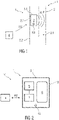
- figure 1 shows schematically an embodiment of a measuring device 1 for detecting particles P in a pipeline 2, for example a pipeline system, in particular a drinking water system.
- the pipeline 2 is, for example, part of a fluid transport system FT, in particular a water transport system.
- the measuring device 1 comprises at least one detection unit 3, which is arranged in a tube interior 2.1.
- the pipeline section shown is, for example, a riser section or a dead pipe section of the pipeline 2.
- the detection unit 3 is designed, for example, as an electronic measuring device.
- the detection unit 3 is, for example, a stationary measuring device in the pipeline 2 .
- the interior of the tube 2.1 has a medium M.
- the medium M is, for example, water and/or drinking water.
- the medium M flows through the tube interior 2.1.
- the medium M is in pipeline 2.
- the detection unit 3 is designed to detect at least one occurrence of different particles P, in particular particles that are harmful to health, in the medium M.
- the measuring device 1 is designed as a stationary assembly module in the pipeline 2 and includes a housing 3.1 which surrounds and encapsulates the detection unit 3.
- the housing 3.1 can be designed in one or more parts.
- the housing 3.1 is designed to be permeable to the medium.
- the detection unit 3 is designed to classify and quantify biological particles P in the water and/or drinking water.
- biological particles P include fungi and bacteria, such as E. coli (Escherichia coli, E.coli for short), legionella or other harmful particles and/or pests.
- E. coli Erscherichia coli, E.coli for short
- legionella bacterium
- particles P carried along in the medium M can be detected by the detection unit 3 .
- the detection unit 3 is designed to classify particle types.
- the detection unit 3 is designed to record a particle proportion (volume proportion), a particle concentration (volume concentration), a volume ratio, for example in percent by volume (vol%) in relation to a volume of the medium M and/or a particle density and/or a mass proportion (mass -%) to determine.
- the detection unit 3 is designed, for example, for a liquid medium M to flow through. Alternatively or additionally, the detection unit 3 is designed to be in the medium M.
- the detection unit 3 is fastened or detachably fastened to an inner wall section 2.2 of the pipeline 2, for example.
- the housing 3.1 is fixed to the inner wall section 2.2.
- the detection unit 3 is designed to be smaller than the cross section of the pipeline 2, for example.
- a dimension, such as a diameter, of the detection unit 3 corresponds to the cross section of the pipeline 2.
- the housing 3.1 can, for example, be made smaller than the cross section of the pipeline 2 or have a dimension that corresponds to the dimension of the pipeline 2, in particular in cross section .
- the housing 3.1 includes fixing elements 3.2.
- the fixing elements 3.2 are, for example, screw elements, rivet elements, clips or other locking elements.
- the fixing elements 3.2 are materially bonded connection elements.
- the fixing elements 3.2 are welding or soldering elements.
- the detection unit 3 includes a filter unit 6, which is designed to provide the particles P to be detected with a fluorescent marking.
- the detection unit 3 is designed to detect fluorescent particles P.
- the detection unit 3 comprises a plurality of particles, for example suitable antibodies which can react with different particles P.
- the particles P can be excited by the particles, so that the particles P fluoresce.
- a chemical reaction between particle P and particle thus causes a fluorescence that can be detected by the detection unit 3 .
- a biofluorescence can be detected by the detection unit 3 .
- the detection unit 3 comprises, for example, a receiving device, not shown in detail here, through which the medium M can flow.
- the detection unit 3 includes a sensor, for example.
- the detection unit 3 is designed to determine the occurrence of particles P and/or a particle concentration and/or a particle density using pattern recognition and/or a pattern comparison and/or an algorithm.
- the detection unit 3 includes, for example, an evaluation unit 7.
- the evaluation unit 7 is embedded in the detection unit 3 in the form of evaluation electronics, including software and algorithms.
- recorded data is transmitted wirelessly.
- the detection unit 3 is designed to communicate with stationary or mobile data processing units 4 .
- the detection unit 3 has a number of interfaces, in particular communication interfaces KS.
- Data determined and/or recorded by means of the recording unit 3 can be transmitted to customers via the data processing unit 4 .
- the acquisition unit 3 is set up to evaluate acquired data itself and to transmit this as ascertained data.
- the detection unit 3 also transmits data that has been purely detected and not evaluated.
- the detection unit 3 is integrated into a network and continuously supplies data about possible water and/or drinking water contamination, which can then be called up by a customer, for example, using application software or another evaluation platform.
- the customer is the operator of the water supply system.
- the detection unit 3 can output information that flushing or other cleaning of the medium M and/or the pipeline 2 should be initiated.
- the determined and/or recorded data can also be transmitted to an accredited laboratory in order, for example, to carry out a correlation between the laboratory result and the data determined using the recording unit 3 .
- the data processing unit 4 is, for example, a user's mobile terminal device or a central server.
- the data processing unit 4 is a computing unit, for example.
- the data processing unit 4 is a so-called cloud storage space, for example.
- the data processing unit 4 is set up to receive data from the detection unit 3 with the detection unit 3, for example via a wireless network, such as a global network.
- the measuring device 1 is set up to acquire data directly and to transmit this via the communication interface KS.
- the communication interface KS is designed as a radio interface.
- the communication interface KS is designed to connect the detection unit 3 to the data processing unit 4 .
- the data is transmitted to the data processing unit 4 so that a user and/or a customer receives up-to-date information about the medium M in a timely manner.
- the data is transmitted to the data processing unit 4 so that the data can be recorded and checked by a laboratory, for example.
- the detection unit 3 can include a control unit. Alternatively, a separate control unit (not shown in detail) can be provided in the measuring device 1 .
- the detection unit 3 and the control unit are data-related coupled with each other.
- the measuring device 1 and/or the detection unit 3 can include a memory (not shown) for storing detected and/or determined data.
- the detection unit 3 can be controlled via the control unit.
- the detection unit 3 can be configured via the control unit.
- a communication link KV can be set up or set up between the detection unit 3 and the data processing unit 4 for data transmission.
- the communication connection KV takes place via one or more communication interfaces KS.
- the housing 3.1 surrounds and encapsulates the detection unit 3 and the at least one communication interface KS.
- the invention also relates to a pipeline 2 with a pipe interior 2.1 and a medium M located in the pipe interior 2.1, with at least one measuring device 1 according to the above description being arranged in the pipe interior 2.1.
- the detection unit 3 By means of the arrangement of the detection unit 3 directly in the pipe interior 2.1, this can be monitored continuously/permanently and/or at definable time intervals and/or when a command is input in a comparatively uncomplicated manner.
- the acquisition unit 3 is designed, for example, to acquire data on the state of the medium M at definable time intervals.
- the medium M transported and/or located in the pipeline 2 can be checked for hygiene in an uncomplicated manner, in particular compared to the prior art.
- figure 2 1 schematically shows an embodiment of a measuring device 1 with at least one detection unit 3 for detecting particles P in a pipeline 2 of a fluid transport system FT. Furthermore shows figure 2 a device V for the transmission of data from the pipeline 2.
- the detection unit 3 comprises at least one camera unit 5 for detecting the particles P carried along in the medium M.
- the detection unit 3 comprises at least one filter unit 6.
- the filter unit 6 is provided to provide the particles P to be detected with a fluorescent marking. As soon as the medium M comes into contact with the filter unit 6, the particles P can be provided with the fluorescent marking.
- the filter unit 6 comprises a plurality of particles, in particular antibodies, which trigger a chemical reaction on a particle surface when they come into contact with particles P, which are particularly harmful to health, as a result of which the particles P fluoresce.
- the camera unit 5 is designed to be able to capture the fluorescent particles P.
- the camera unit 5 is configured to capture the fluorescent particles P in the so-called VIS range. Recorded data, such as image data, are then evaluated.
- the camera unit 5 is coupled to an evaluation unit 7 .
- the evaluation unit 7 is designed in the form of evaluation electronics, comprising at least software and algorithms, for evaluating the recorded data.
- the occurrence of the particles P and/or a particle concentration and/or a particle density can be detected using pattern recognition and/or a pattern comparison and/or an algorithm.
- the particles P are quantified by determining a surface (determined by integration) that is covered by particles P in the camera image. Subsequently, recorded data on the particle-covered surface are set in relation to the entire recorded surface in the pipe interior 2.1.
- the evaluation unit 7 works, for example, with what is known as pattern matching or a learning algorithm in order to classify and quantify the particles P. A learning process can be carried out in order to configure the algorithm with regard to a classification.
- the device V includes the measuring device 1 and a data processing unit 4.
- the measuring device 1 and the data processing unit 4 can be connected to one another via a communication link KV, in particular a wireless communication link KV.
Landscapes
- Chemical & Material Sciences (AREA)
- Health & Medical Sciences (AREA)
- Life Sciences & Earth Sciences (AREA)
- Pathology (AREA)
- Physics & Mathematics (AREA)
- Analytical Chemistry (AREA)
- Biochemistry (AREA)
- General Health & Medical Sciences (AREA)
- General Physics & Mathematics (AREA)
- Immunology (AREA)
- Dispersion Chemistry (AREA)
- Engineering & Computer Science (AREA)
- Food Science & Technology (AREA)
- Medicinal Chemistry (AREA)
- Signal Processing (AREA)
- Measuring Or Testing Involving Enzymes Or Micro-Organisms (AREA)
Claims (13)
- Conduite (2) comprenant un dispositif de mesure (1) destiné à détecter des particules (P), le dispositif de mesure (1) comprenant- au moins une unité de détection (3) qui est disposée dans un espace intérieur (2.1) de la conduite (2), l'espace intérieur (2.1) comportant un milieu (M) et/ou pouvant être traversé par un milieu (M), et- l'unité de détection (3) étant conçue pour détecter au moins une survenance de différentes particules (P) dans le milieu (M), et- l'unité de détection (3) comprenant au moins une unité filtrante (6) qui est conçue pour doter les particules (P) à détecter d'un marqueur à fluorescence.
- Conduite (2) selon la revendication 1, l'unité de détection (3) étant conçue pour classer et quantifier des particules biologiques (P) dans l'eau et/ou l'eau potable.
- Conduite (2) selon la revendication 1 ou 2, l'unité de détection (3) étant disposée dans une portion de conduite montante ou une portion de conduite morte de la conduite (2).
- Conduite (2) selon l'une des revendications précédentes, l'unité de détection (3) étant conçue pour détecter des particules fluorescentes (P).
- Conduite (2) selon l'une des revendications précédentes, l'unité de détection (3) comprenant au moins une unité formant caméra (5).
- Conduite (2) selon l'une des revendications précédentes, l'unité de détection (3) étant fixée de manière au moins partiellement amovible dans l'espace intérieur (2.1).
- Conduite (2) selon l'une des revendications précédentes, l'unité de détection (3) étant conçue pour déterminer la survenance de particules (P) et/ou une concentration de particules et/ou une densité de particules sur la base d'une reconnaissance de formes et/ou d'un algorithme.
- Conduite (2) selon l'une des revendications précédentes, l'unité de détection (3) étant conçue pour transmettre au moins des données déterminées à une unité de traitement de données (4).
- Conduite (2) selon l'une des revendications précédentes, l'unité de détection (3) comprenant au moins une unité d'évaluation (7).
- Conduite (2) selon l'une des revendications précédentes, l'unité de détection (3) étant réglée pour vérifier le milieu (M) en continu et/ou à des intervalles de temps spécifiables pour rechercher des particules nocives (P).
- Conduite (2) selon l'une des revendications précédentes, l'unité de détection (3) comportant au moins une interface de communication (KS) permettant à l'unité de détection (3) de transmettre au moins des données déterminées.
- Dispositif (V) destiné à transmettre des données provenant d'une conduite (2), ledit dispositif comprenant- au moins un dispositif de mesure (1) selon l'une des revendications précédentes 1 à 11, et- au moins une unité de traitement de données (4) couplée et/ou pouvant être couplée au dispositif de mesure (1), le dispositif de mesure (1) transmettant sans fil des données acquises et/ou des données déterminées à l'unité de traitement de données (4).
- Dispositif (V) selon la revendication 12, le dispositif de mesure (1) transmettant des données acquises et/ou des données déterminées de manière continue et/ou à des intervalles de temps spécifiables à l'unité de traitement de données (4).
Applications Claiming Priority (1)
| Application Number | Priority Date | Filing Date | Title |
|---|---|---|---|
| DE102019204668.1A DE102019204668A1 (de) | 2019-04-02 | 2019-04-02 | Messvorrichtung zur Erfassung von Partikeln in einer Rohrleitung und Rohrleitung |
Publications (2)
| Publication Number | Publication Date |
|---|---|
| EP3719476A1 EP3719476A1 (fr) | 2020-10-07 |
| EP3719476B1 true EP3719476B1 (fr) | 2023-01-11 |
Family
ID=70165848
Family Applications (1)
| Application Number | Title | Priority Date | Filing Date |
|---|---|---|---|
| EP20167758.0A Active EP3719476B1 (fr) | 2019-04-02 | 2020-04-02 | Conduite comprenant dispositif de mesure permettant de détecter des particules et dispositif pour la transmission de dates depuis la conduite |
Country Status (2)
| Country | Link |
|---|---|
| EP (1) | EP3719476B1 (fr) |
| DE (1) | DE102019204668A1 (fr) |
Families Citing this family (2)
| Publication number | Priority date | Publication date | Assignee | Title |
|---|---|---|---|---|
| EP4012381B1 (fr) * | 2020-12-09 | 2025-11-26 | Wilde, Axel | Dispositif et procédé de détection des particules dans des liquides et des gaz |
| CN113960970A (zh) * | 2021-10-27 | 2022-01-21 | 西安热工研究院有限公司 | 一种树脂输送过程智能监控系统及方法 |
Family Cites Families (10)
| Publication number | Priority date | Publication date | Assignee | Title |
|---|---|---|---|---|
| DE2632556C2 (de) * | 1976-07-20 | 1984-09-20 | Max Planck Gesellschaft zur Förderung der Wissenschaften e.V., 3400 Göttingen | Lichtzuführung für eine Vorrichtung zur optischen Messung von Stoffkonzentrationen |
| GB8408529D0 (en) * | 1984-04-03 | 1984-05-16 | Health Lab Service Board | Concentration of biological particles |
| ES2251722T3 (es) * | 1994-08-01 | 2006-05-01 | Abbott Laboratories | Procedimiento y aparato para la realizacion de analisis automatizados. |
| US5948684A (en) * | 1997-03-31 | 1999-09-07 | University Of Washington | Simultaneous analyte determination and reference balancing in reference T-sensor devices |
| AT407802B (de) * | 1998-02-26 | 2001-06-25 | Staudinger Gernot | Vorrichtung zur messung der zeitlichen entwicklung der transparenz eines in einer küvette sedimentierenden klärschlammes |
| EP2349932A1 (fr) * | 2008-11-05 | 2011-08-03 | Age SA | Configuration de capteurs et procédé de contrôle de la qualité de l'eau |
| DE102012108989B3 (de) * | 2012-09-24 | 2014-01-23 | Eads Deutschland Gmbh | Detektionsvorrichtung sowie Verfahren zur automatischen Detektion von Partikeln |
| FR3024545B1 (fr) * | 2014-07-30 | 2018-05-18 | Suez Environnement | Systeme de mesure intelligent au point de livraison d'un fluide |
| WO2017143332A1 (fr) * | 2016-02-18 | 2017-08-24 | Optofluidics, Inc. | Système et procédé de caractérisation de particules dans un échantillon de fluide |
| FR3053359B1 (fr) * | 2016-06-30 | 2021-01-08 | Suez Groupe | Procede de controle de la concentration de bacteries dans un reseau de distribution d'eau |
-
2019
- 2019-04-02 DE DE102019204668.1A patent/DE102019204668A1/de not_active Ceased
-
2020
- 2020-04-02 EP EP20167758.0A patent/EP3719476B1/fr active Active
Also Published As
| Publication number | Publication date |
|---|---|
| DE102019204668A1 (de) | 2020-10-08 |
| EP3719476A1 (fr) | 2020-10-07 |
Similar Documents
| Publication | Publication Date | Title |
|---|---|---|
| DE102012108989B3 (de) | Detektionsvorrichtung sowie Verfahren zur automatischen Detektion von Partikeln | |
| DE102009029305A1 (de) | Analysegerät zur automatisierten Bestimmung einer Messgröße einer Flüssigkeitsprobe | |
| WO2016192966A1 (fr) | Procédé de diagnostic d'une vanne à membrane, et système de diagnostic pour vanne à membrane | |
| DE102017126612A1 (de) | Messeinrichtung zur Analyse eines Messmediums | |
| DE102011088235A1 (de) | Probenvorbereitungseinrichtung für eine Analyseeinrichtung zur Bestimmung einer Messgröße einer flüssigen Probe | |
| DE102012102296A1 (de) | Messanordnung umfassend mindestens ein erstes Analysegerät zur automatisierten Bestimmung einer Messgröße einer Flüssigkeit und eine Probenvorbereitungseinrichtung | |
| DE102010053749B4 (de) | Vorrichtung zum Identifizieren biotischer Partikel | |
| EP3719476A1 (fr) | Conduite comprenant un dispositif de mesure permettant de détecter des particules et dispositif pour la transmission de dates depuis la conduite | |
| EP4118039B1 (fr) | Systeme pour analyser de l'eau | |
| EP3130926B1 (fr) | Procédé de fourniture d'un mélange reactionnel et un appareil d'analyse automatique | |
| EP1743227B1 (fr) | Appareil de terrain electrique pour l'automatisation de processus | |
| DE102008016763A1 (de) | Vorrichtung und Verfahren zum chromatographischen Nachweis einer Substanz | |
| EP2539688B1 (fr) | Procédé et dispositif pour déterminer la qualité des résultats de mesure d'un appareil de mesure de lumière diffusée | |
| DE102020100237A1 (de) | Verfahren zur qualitätskontrolle an in einer fluidleitung strömendem fluid | |
| EP4150311A1 (fr) | Appareil et procédé d'échantillonnage automatique permettant la fourniture automatique d'un échantillon pour la détermination qualitative et/ou quantitative d'un anaylte | |
| WO2017114592A1 (fr) | Dispositif pour contrôler la réactivité d'un capteur en tenant compte du nouvel état | |
| DE19610475C1 (de) | Vorrichtung zur Auffindung von Leckagen in Rohren, insbesondere Kanalisationsrohren | |
| WO2018054686A1 (fr) | Dispositif portatif permettant de diagnostiquer un appareil de réglage acheminant un fluide de traitement, et procédé de diagnostic de l'état d'un appareil de réglage acheminant un fluide de traitement | |
| DE102015102289A1 (de) | Vorrichtung zur Entnahme von Proben aus einer in einer Leitung fließenden Prozessflüssigkeit | |
| EP3097974A1 (fr) | Agitateur magnétique pour un système de diagnostic in vitro | |
| DE102015015150B4 (de) | Gasmesssystem mit einer Gasmessvorrichtung und einer Kontrolleinrichtung und Verfahren zum Betrieb einer Gasmessvorrichtung mittels einer Kontrolleinrichtung | |
| EP1775032B1 (fr) | Dispositif de nettoyage de surfaces | |
| DE102006030310B3 (de) | Verfahren zur Analyse einer Flüssigkeit aus einem Flüssigkeitsstrom oder -vorrat, sowie Vorrichtung zur Durchführung dieses Verfahrens | |
| DE102011007309A1 (de) | Verfahren und Vorrichtung zur Verschmutzungs- und Reinigungsvalidierung einer Anlage | |
| DE4416203C2 (de) | Einrichtung zum Bestimmen von Schadstoffen in einem flüssigen Brennstoff |
Legal Events
| Date | Code | Title | Description |
|---|---|---|---|
| PUAI | Public reference made under article 153(3) epc to a published international application that has entered the european phase |
Free format text: ORIGINAL CODE: 0009012 |
|
| STAA | Information on the status of an ep patent application or granted ep patent |
Free format text: STATUS: THE APPLICATION HAS BEEN PUBLISHED |
|
| AK | Designated contracting states |
Kind code of ref document: A1 Designated state(s): AL AT BE BG CH CY CZ DE DK EE ES FI FR GB GR HR HU IE IS IT LI LT LU LV MC MK MT NL NO PL PT RO RS SE SI SK SM TR |
|
| AX | Request for extension of the european patent |
Extension state: BA ME |
|
| STAA | Information on the status of an ep patent application or granted ep patent |
Free format text: STATUS: REQUEST FOR EXAMINATION WAS MADE |
|
| 17P | Request for examination filed |
Effective date: 20210407 |
|
| RBV | Designated contracting states (corrected) |
Designated state(s): AL AT BE BG CH CY CZ DE DK EE ES FI FR GB GR HR HU IE IS IT LI LT LU LV MC MK MT NL NO PL PT RO RS SE SI SK SM TR |
|
| GRAP | Despatch of communication of intention to grant a patent |
Free format text: ORIGINAL CODE: EPIDOSNIGR1 |
|
| STAA | Information on the status of an ep patent application or granted ep patent |
Free format text: STATUS: GRANT OF PATENT IS INTENDED |
|
| INTG | Intention to grant announced |
Effective date: 20220817 |
|
| GRAS | Grant fee paid |
Free format text: ORIGINAL CODE: EPIDOSNIGR3 |
|
| GRAA | (expected) grant |
Free format text: ORIGINAL CODE: 0009210 |
|
| STAA | Information on the status of an ep patent application or granted ep patent |
Free format text: STATUS: THE PATENT HAS BEEN GRANTED |
|
| AK | Designated contracting states |
Kind code of ref document: B1 Designated state(s): AL AT BE BG CH CY CZ DE DK EE ES FI FR GB GR HR HU IE IS IT LI LT LU LV MC MK MT NL NO PL PT RO RS SE SI SK SM TR |
|
| REG | Reference to a national code |
Ref country code: GB Ref legal event code: FG4D Free format text: NOT ENGLISH |
|
| REG | Reference to a national code |
Ref country code: CH Ref legal event code: EP |
|
| REG | Reference to a national code |
Ref country code: DE Ref legal event code: R096 Ref document number: 502020002332 Country of ref document: DE |
|
| REG | Reference to a national code |
Ref country code: IE Ref legal event code: FG4D Free format text: LANGUAGE OF EP DOCUMENT: GERMAN |
|
| REG | Reference to a national code |
Ref country code: AT Ref legal event code: REF Ref document number: 1543704 Country of ref document: AT Kind code of ref document: T Effective date: 20230215 |
|
| REG | Reference to a national code |
Ref country code: LT Ref legal event code: MG9D |
|
| REG | Reference to a national code |
Ref country code: NL Ref legal event code: MP Effective date: 20230111 |
|
| PG25 | Lapsed in a contracting state [announced via postgrant information from national office to epo] |
Ref country code: NL Free format text: LAPSE BECAUSE OF FAILURE TO SUBMIT A TRANSLATION OF THE DESCRIPTION OR TO PAY THE FEE WITHIN THE PRESCRIBED TIME-LIMIT Effective date: 20230111 |
|
| PG25 | Lapsed in a contracting state [announced via postgrant information from national office to epo] |
Ref country code: RS Free format text: LAPSE BECAUSE OF FAILURE TO SUBMIT A TRANSLATION OF THE DESCRIPTION OR TO PAY THE FEE WITHIN THE PRESCRIBED TIME-LIMIT Effective date: 20230111 Ref country code: PT Free format text: LAPSE BECAUSE OF FAILURE TO SUBMIT A TRANSLATION OF THE DESCRIPTION OR TO PAY THE FEE WITHIN THE PRESCRIBED TIME-LIMIT Effective date: 20230511 Ref country code: NO Free format text: LAPSE BECAUSE OF FAILURE TO SUBMIT A TRANSLATION OF THE DESCRIPTION OR TO PAY THE FEE WITHIN THE PRESCRIBED TIME-LIMIT Effective date: 20230411 Ref country code: LV Free format text: LAPSE BECAUSE OF FAILURE TO SUBMIT A TRANSLATION OF THE DESCRIPTION OR TO PAY THE FEE WITHIN THE PRESCRIBED TIME-LIMIT Effective date: 20230111 Ref country code: LT Free format text: LAPSE BECAUSE OF FAILURE TO SUBMIT A TRANSLATION OF THE DESCRIPTION OR TO PAY THE FEE WITHIN THE PRESCRIBED TIME-LIMIT Effective date: 20230111 Ref country code: HR Free format text: LAPSE BECAUSE OF FAILURE TO SUBMIT A TRANSLATION OF THE DESCRIPTION OR TO PAY THE FEE WITHIN THE PRESCRIBED TIME-LIMIT Effective date: 20230111 Ref country code: ES Free format text: LAPSE BECAUSE OF FAILURE TO SUBMIT A TRANSLATION OF THE DESCRIPTION OR TO PAY THE FEE WITHIN THE PRESCRIBED TIME-LIMIT Effective date: 20230111 |
|
| PG25 | Lapsed in a contracting state [announced via postgrant information from national office to epo] |
Ref country code: SE Free format text: LAPSE BECAUSE OF FAILURE TO SUBMIT A TRANSLATION OF THE DESCRIPTION OR TO PAY THE FEE WITHIN THE PRESCRIBED TIME-LIMIT Effective date: 20230111 Ref country code: PL Free format text: LAPSE BECAUSE OF FAILURE TO SUBMIT A TRANSLATION OF THE DESCRIPTION OR TO PAY THE FEE WITHIN THE PRESCRIBED TIME-LIMIT Effective date: 20230111 Ref country code: IS Free format text: LAPSE BECAUSE OF FAILURE TO SUBMIT A TRANSLATION OF THE DESCRIPTION OR TO PAY THE FEE WITHIN THE PRESCRIBED TIME-LIMIT Effective date: 20230511 Ref country code: GR Free format text: LAPSE BECAUSE OF FAILURE TO SUBMIT A TRANSLATION OF THE DESCRIPTION OR TO PAY THE FEE WITHIN THE PRESCRIBED TIME-LIMIT Effective date: 20230412 Ref country code: FI Free format text: LAPSE BECAUSE OF FAILURE TO SUBMIT A TRANSLATION OF THE DESCRIPTION OR TO PAY THE FEE WITHIN THE PRESCRIBED TIME-LIMIT Effective date: 20230111 |
|
| REG | Reference to a national code |
Ref country code: DE Ref legal event code: R097 Ref document number: 502020002332 Country of ref document: DE |
|
| PG25 | Lapsed in a contracting state [announced via postgrant information from national office to epo] |
Ref country code: SM Free format text: LAPSE BECAUSE OF FAILURE TO SUBMIT A TRANSLATION OF THE DESCRIPTION OR TO PAY THE FEE WITHIN THE PRESCRIBED TIME-LIMIT Effective date: 20230111 Ref country code: RO Free format text: LAPSE BECAUSE OF FAILURE TO SUBMIT A TRANSLATION OF THE DESCRIPTION OR TO PAY THE FEE WITHIN THE PRESCRIBED TIME-LIMIT Effective date: 20230111 Ref country code: EE Free format text: LAPSE BECAUSE OF FAILURE TO SUBMIT A TRANSLATION OF THE DESCRIPTION OR TO PAY THE FEE WITHIN THE PRESCRIBED TIME-LIMIT Effective date: 20230111 Ref country code: DK Free format text: LAPSE BECAUSE OF FAILURE TO SUBMIT A TRANSLATION OF THE DESCRIPTION OR TO PAY THE FEE WITHIN THE PRESCRIBED TIME-LIMIT Effective date: 20230111 Ref country code: CZ Free format text: LAPSE BECAUSE OF FAILURE TO SUBMIT A TRANSLATION OF THE DESCRIPTION OR TO PAY THE FEE WITHIN THE PRESCRIBED TIME-LIMIT Effective date: 20230111 |
|
| REG | Reference to a national code |
Ref country code: DE Ref legal event code: R119 Ref document number: 502020002332 Country of ref document: DE |
|
| PLBE | No opposition filed within time limit |
Free format text: ORIGINAL CODE: 0009261 |
|
| STAA | Information on the status of an ep patent application or granted ep patent |
Free format text: STATUS: NO OPPOSITION FILED WITHIN TIME LIMIT |
|
| PG25 | Lapsed in a contracting state [announced via postgrant information from national office to epo] |
Ref country code: SK Free format text: LAPSE BECAUSE OF FAILURE TO SUBMIT A TRANSLATION OF THE DESCRIPTION OR TO PAY THE FEE WITHIN THE PRESCRIBED TIME-LIMIT Effective date: 20230111 |
|
| REG | Reference to a national code |
Ref country code: CH Ref legal event code: PL |
|
| 26N | No opposition filed |
Effective date: 20231012 |
|
| PG25 | Lapsed in a contracting state [announced via postgrant information from national office to epo] |
Ref country code: LU Free format text: LAPSE BECAUSE OF NON-PAYMENT OF DUE FEES Effective date: 20230402 |
|
| REG | Reference to a national code |
Ref country code: BE Ref legal event code: MM Effective date: 20230430 |
|
| PG25 | Lapsed in a contracting state [announced via postgrant information from national office to epo] |
Ref country code: MC Free format text: LAPSE BECAUSE OF FAILURE TO SUBMIT A TRANSLATION OF THE DESCRIPTION OR TO PAY THE FEE WITHIN THE PRESCRIBED TIME-LIMIT Effective date: 20230111 |
|
| PG25 | Lapsed in a contracting state [announced via postgrant information from national office to epo] |
Ref country code: SI Free format text: LAPSE BECAUSE OF FAILURE TO SUBMIT A TRANSLATION OF THE DESCRIPTION OR TO PAY THE FEE WITHIN THE PRESCRIBED TIME-LIMIT Effective date: 20230111 Ref country code: MC Free format text: LAPSE BECAUSE OF FAILURE TO SUBMIT A TRANSLATION OF THE DESCRIPTION OR TO PAY THE FEE WITHIN THE PRESCRIBED TIME-LIMIT Effective date: 20230111 Ref country code: LI Free format text: LAPSE BECAUSE OF NON-PAYMENT OF DUE FEES Effective date: 20230430 Ref country code: FR Free format text: LAPSE BECAUSE OF NON-PAYMENT OF DUE FEES Effective date: 20230430 Ref country code: DE Free format text: LAPSE BECAUSE OF NON-PAYMENT OF DUE FEES Effective date: 20231103 Ref country code: CH Free format text: LAPSE BECAUSE OF NON-PAYMENT OF DUE FEES Effective date: 20230430 |
|
| REG | Reference to a national code |
Ref country code: IE Ref legal event code: MM4A |
|
| PG25 | Lapsed in a contracting state [announced via postgrant information from national office to epo] |
Ref country code: BE Free format text: LAPSE BECAUSE OF NON-PAYMENT OF DUE FEES Effective date: 20230430 |
|
| PG25 | Lapsed in a contracting state [announced via postgrant information from national office to epo] |
Ref country code: IE Free format text: LAPSE BECAUSE OF NON-PAYMENT OF DUE FEES Effective date: 20230402 |
|
| PG25 | Lapsed in a contracting state [announced via postgrant information from national office to epo] |
Ref country code: IE Free format text: LAPSE BECAUSE OF NON-PAYMENT OF DUE FEES Effective date: 20230402 |
|
| PG25 | Lapsed in a contracting state [announced via postgrant information from national office to epo] |
Ref country code: IT Free format text: LAPSE BECAUSE OF FAILURE TO SUBMIT A TRANSLATION OF THE DESCRIPTION OR TO PAY THE FEE WITHIN THE PRESCRIBED TIME-LIMIT Effective date: 20230111 |
|
| PG25 | Lapsed in a contracting state [announced via postgrant information from national office to epo] |
Ref country code: BG Free format text: LAPSE BECAUSE OF FAILURE TO SUBMIT A TRANSLATION OF THE DESCRIPTION OR TO PAY THE FEE WITHIN THE PRESCRIBED TIME-LIMIT Effective date: 20230111 |
|
| PG25 | Lapsed in a contracting state [announced via postgrant information from national office to epo] |
Ref country code: BG Free format text: LAPSE BECAUSE OF FAILURE TO SUBMIT A TRANSLATION OF THE DESCRIPTION OR TO PAY THE FEE WITHIN THE PRESCRIBED TIME-LIMIT Effective date: 20230111 |
|
| GBPC | Gb: european patent ceased through non-payment of renewal fee |
Effective date: 20240402 |
|
| PG25 | Lapsed in a contracting state [announced via postgrant information from national office to epo] |
Ref country code: GB Free format text: LAPSE BECAUSE OF NON-PAYMENT OF DUE FEES Effective date: 20240402 |
|
| PG25 | Lapsed in a contracting state [announced via postgrant information from national office to epo] |
Ref country code: GB Free format text: LAPSE BECAUSE OF NON-PAYMENT OF DUE FEES Effective date: 20240402 |
|
| PGFP | Annual fee paid to national office [announced via postgrant information from national office to epo] |
Ref country code: AT Payment date: 20250721 Year of fee payment: 5 |
|
| PG25 | Lapsed in a contracting state [announced via postgrant information from national office to epo] |
Ref country code: CY Free format text: LAPSE BECAUSE OF FAILURE TO SUBMIT A TRANSLATION OF THE DESCRIPTION OR TO PAY THE FEE WITHIN THE PRESCRIBED TIME-LIMIT; INVALID AB INITIO Effective date: 20200402 |
|
| PG25 | Lapsed in a contracting state [announced via postgrant information from national office to epo] |
Ref country code: HU Free format text: LAPSE BECAUSE OF FAILURE TO SUBMIT A TRANSLATION OF THE DESCRIPTION OR TO PAY THE FEE WITHIN THE PRESCRIBED TIME-LIMIT; INVALID AB INITIO Effective date: 20200402 |
|
| PG25 | Lapsed in a contracting state [announced via postgrant information from national office to epo] |
Ref country code: TR Free format text: LAPSE BECAUSE OF FAILURE TO SUBMIT A TRANSLATION OF THE DESCRIPTION OR TO PAY THE FEE WITHIN THE PRESCRIBED TIME-LIMIT Effective date: 20230111 |
|
| REG | Reference to a national code |
Ref country code: AT Ref legal event code: MM01 Ref document number: 1543704 Country of ref document: AT Kind code of ref document: T Effective date: 20250402 |
|
| PG25 | Lapsed in a contracting state [announced via postgrant information from national office to epo] |
Ref country code: AT Free format text: LAPSE BECAUSE OF NON-PAYMENT OF DUE FEES Effective date: 20250402 |