EP3720518B1 - Pansement à pression négative actionné manuellement (npwt) équipé d'une pompe plus efficace, d'un indicateur de pression automatique et d'un limiteur de pression automatique - Google Patents
Pansement à pression négative actionné manuellement (npwt) équipé d'une pompe plus efficace, d'un indicateur de pression automatique et d'un limiteur de pression automatique Download PDFInfo
- Publication number
- EP3720518B1 EP3720518B1 EP18886192.6A EP18886192A EP3720518B1 EP 3720518 B1 EP3720518 B1 EP 3720518B1 EP 18886192 A EP18886192 A EP 18886192A EP 3720518 B1 EP3720518 B1 EP 3720518B1
- Authority
- EP
- European Patent Office
- Prior art keywords
- wound
- pump body
- pump
- membrane
- atmosphere
- Prior art date
- Legal status (The legal status is an assumption and is not a legal conclusion. Google has not performed a legal analysis and makes no representation as to the accuracy of the status listed.)
- Active
Links
Images





Classifications
-
- A—HUMAN NECESSITIES
- A61—MEDICAL OR VETERINARY SCIENCE; HYGIENE
- A61F—FILTERS IMPLANTABLE INTO BLOOD VESSELS; PROSTHESES; DEVICES PROVIDING PATENCY TO, OR PREVENTING COLLAPSING OF, TUBULAR STRUCTURES OF THE BODY, e.g. STENTS; ORTHOPAEDIC, NURSING OR CONTRACEPTIVE DEVICES; FOMENTATION; TREATMENT OR PROTECTION OF EYES OR EARS; BANDAGES, DRESSINGS OR ABSORBENT PADS; FIRST-AID KITS
- A61F13/00—Bandages or dressings; Absorbent pads
- A61F13/02—Adhesive bandages or dressings
- A61F13/0203—Adhesive bandages or dressings with fluid retention members
- A61F13/0206—Adhesive bandages or dressings with fluid retention members with absorbent fibrous layers, e.g. woven or non-woven absorbent pads or island dressings
-
- A—HUMAN NECESSITIES
- A61—MEDICAL OR VETERINARY SCIENCE; HYGIENE
- A61F—FILTERS IMPLANTABLE INTO BLOOD VESSELS; PROSTHESES; DEVICES PROVIDING PATENCY TO, OR PREVENTING COLLAPSING OF, TUBULAR STRUCTURES OF THE BODY, e.g. STENTS; ORTHOPAEDIC, NURSING OR CONTRACEPTIVE DEVICES; FOMENTATION; TREATMENT OR PROTECTION OF EYES OR EARS; BANDAGES, DRESSINGS OR ABSORBENT PADS; FIRST-AID KITS
- A61F13/00—Bandages or dressings; Absorbent pads
- A61F13/02—Adhesive bandages or dressings
- A61F13/0203—Adhesive bandages or dressings with fluid retention members
- A61F13/022—Adhesive bandages or dressings with fluid retention members having more than one layer with different fluid retention characteristics
-
- A—HUMAN NECESSITIES
- A61—MEDICAL OR VETERINARY SCIENCE; HYGIENE
- A61F—FILTERS IMPLANTABLE INTO BLOOD VESSELS; PROSTHESES; DEVICES PROVIDING PATENCY TO, OR PREVENTING COLLAPSING OF, TUBULAR STRUCTURES OF THE BODY, e.g. STENTS; ORTHOPAEDIC, NURSING OR CONTRACEPTIVE DEVICES; FOMENTATION; TREATMENT OR PROTECTION OF EYES OR EARS; BANDAGES, DRESSINGS OR ABSORBENT PADS; FIRST-AID KITS
- A61F13/00—Bandages or dressings; Absorbent pads
- A61F13/05—Bandages or dressings; Absorbent pads specially adapted for use with sub-pressure or over-pressure therapy, wound drainage or wound irrigation, e.g. for use with negative-pressure wound therapy [NPWT]
-
- A—HUMAN NECESSITIES
- A61—MEDICAL OR VETERINARY SCIENCE; HYGIENE
- A61M—DEVICES FOR INTRODUCING MEDIA INTO, OR ONTO, THE BODY; DEVICES FOR TRANSDUCING BODY MEDIA OR FOR TAKING MEDIA FROM THE BODY; DEVICES FOR PRODUCING OR ENDING SLEEP OR STUPOR
- A61M1/00—Suction or pumping devices for medical purposes; Devices for carrying-off, for treatment of, or for carrying-over, body-liquids; Drainage systems
- A61M1/71—Suction drainage systems
- A61M1/73—Suction drainage systems comprising sensors or indicators for physical values
- A61M1/732—Visual indicating means for vacuum pressure
-
- A—HUMAN NECESSITIES
- A61—MEDICAL OR VETERINARY SCIENCE; HYGIENE
- A61M—DEVICES FOR INTRODUCING MEDIA INTO, OR ONTO, THE BODY; DEVICES FOR TRANSDUCING BODY MEDIA OR FOR TAKING MEDIA FROM THE BODY; DEVICES FOR PRODUCING OR ENDING SLEEP OR STUPOR
- A61M1/00—Suction or pumping devices for medical purposes; Devices for carrying-off, for treatment of, or for carrying-over, body-liquids; Drainage systems
- A61M1/90—Negative pressure wound therapy devices, i.e. devices for applying suction to a wound to promote healing, e.g. including a vacuum dressing
- A61M1/91—Suction aspects of the dressing
- A61M1/915—Constructional details of the pressure distribution manifold
-
- A—HUMAN NECESSITIES
- A61—MEDICAL OR VETERINARY SCIENCE; HYGIENE
- A61M—DEVICES FOR INTRODUCING MEDIA INTO, OR ONTO, THE BODY; DEVICES FOR TRANSDUCING BODY MEDIA OR FOR TAKING MEDIA FROM THE BODY; DEVICES FOR PRODUCING OR ENDING SLEEP OR STUPOR
- A61M1/00—Suction or pumping devices for medical purposes; Devices for carrying-off, for treatment of, or for carrying-over, body-liquids; Drainage systems
- A61M1/90—Negative pressure wound therapy devices, i.e. devices for applying suction to a wound to promote healing, e.g. including a vacuum dressing
- A61M1/96—Suction control thereof
- A61M1/962—Suction control thereof having pumping means on the suction site, e.g. miniature pump on dressing or dressing capable of exerting suction
-
- A—HUMAN NECESSITIES
- A61—MEDICAL OR VETERINARY SCIENCE; HYGIENE
- A61M—DEVICES FOR INTRODUCING MEDIA INTO, OR ONTO, THE BODY; DEVICES FOR TRANSDUCING BODY MEDIA OR FOR TAKING MEDIA FROM THE BODY; DEVICES FOR PRODUCING OR ENDING SLEEP OR STUPOR
- A61M39/00—Tubes, tube connectors, tube couplings, valves, access sites or the like, specially adapted for medical use
- A61M39/22—Valves or arrangement of valves
- A61M39/24—Check- or non-return valves
-
- A—HUMAN NECESSITIES
- A61—MEDICAL OR VETERINARY SCIENCE; HYGIENE
- A61M—DEVICES FOR INTRODUCING MEDIA INTO, OR ONTO, THE BODY; DEVICES FOR TRANSDUCING BODY MEDIA OR FOR TAKING MEDIA FROM THE BODY; DEVICES FOR PRODUCING OR ENDING SLEEP OR STUPOR
- A61M2205/00—General characteristics of the apparatus
- A61M2205/07—General characteristics of the apparatus having air pumping means
- A61M2205/071—General characteristics of the apparatus having air pumping means hand operated
-
- A—HUMAN NECESSITIES
- A61—MEDICAL OR VETERINARY SCIENCE; HYGIENE
- A61M—DEVICES FOR INTRODUCING MEDIA INTO, OR ONTO, THE BODY; DEVICES FOR TRANSDUCING BODY MEDIA OR FOR TAKING MEDIA FROM THE BODY; DEVICES FOR PRODUCING OR ENDING SLEEP OR STUPOR
- A61M2209/00—Ancillary equipment
- A61M2209/06—Packaging for specific medical equipment
Definitions
- This invention relates to bandages in general, and more particularly to negative pressure wound therapy (NPWT) bandages.
- NGWT negative pressure wound therapy
- WO 2016/182977 A1 details a system and method for providing negative pressure therapy to a tissue site.
- the system includes a dressing assembly with an absorbent layer and a sealing layer, and a blister fluidly coupled to the absorbent layer.
- the blister can shift between a collapsed and an expanded position, and two check valves work to control the fluid flow during this movement.
- the method includes positioning the assembly at the tissue site, compressing the blister to evacuate it, and allowing the blister to expand to draw fluid from the absorbent.
- US 2015/0202354 A1 relates to a wound dressing with an integrated mechanical aspirator for drawing exudates and fluids from the wound.
- the dressing combines the aspirator with an internal absorbent pad for collecting exudate and fluids.
- the pad includes multiple layers such as a layer of hyper-absorbent material, which acts as the fluid collection medium.
- the aspirator is built into the top of the dressing, featuring a hollow bulb head and a one-way purge vent that removes air when manually compressed. Upon releasing the compression, the bulb head expands back to its original shape, thereby creating a vacuum pressure that aids in drawing exudate and fluids from the wound into the pad.
- US 3,486,504 A1 shows a device for applying dressing, medication, and suction to a skin infection.
- the device consists of a resilient bulb-like housing that contains an absorbent dressing and is designed with an open bottom portion. This housing is partially squeezed against the skin, causing the dressing to make contact with the infected area, while also maintaining a partial vacuum within the housing to provide suction.
- the device can also contain a fragile capsule of medication, which is released into the dressing when the housing is squeezed.
- the housing's bottom flange can be adhesively attached to the skin to hold the dressing in contact with the infected area and maintain a seal for the partial vacuum.
- the device can be used for continuous treatment of skin infections such as boils and carbuncles.
- bandages are used to provide wound care during healing. More particularly, bandages generally provide a covering for a wound so as to shield the wound from contaminants and microbes during healing. Most bandages also provide a closure feature to help hold the edges of the wound in close apposition during healing. Bandages also frequently include gauze or the like to receive exudates emerging from the wound during healing.
- Negative pressure wound therapy (NPWT) bandages apply a negative pressure to a wound during healing. This negative pressure helps reduce the likelihood of contaminants and microbes entering the wound during healing, helps draw exudates from the wound during healing, and can promote beneficial biological responses at the wound site. More particularly, NPWT bandages typically comprise (i) an absorbent dressing configured to make a fully-sealed chamber around the perimeter of a wound ("the wound chamber"), (ii) a source of negative pressure, and (iii) a conduit extending between the fully-sealed wound chamber and the source of negative pressure.
- the absorbent dressing can be applied to a wound so as to create a fully-sealed chamber around the perimeter of the wound, and the source of negative pressure can apply a negative pressure to the fully- sealed wound chamber, such that any contaminants and microbes present at the wound site are drawn away from the wound, exudates are drawn out of the wound, and beneficial biological responses are promoted at the wound site.
- NPWT bandages are part of a large, complex NPWT system, in the sense that (i) the absorbent dressings are generally fairly large (e.g., they are sized to cover large open wounds), (ii) the sources of negative pressure are generally fairly large, and formed and located separate from the absorbent
- NPWT bandage where the source of negative pressure is integrated with the absorbent dressing.
- efforts have been made to provide an NPWT bandage where a manually-operated suction pump is integrated into the absorbent dressing.
- NPWT bandages integrating a suction pump with the absorbent dressing tend to suffer from a variety of deficiencies, e.g., they have a complex design, and/or are expensive, and/or are complicated to use, and/or are bulky (including having a high profile), and/or cause additional trauma to the wound during use, and/or have poor pump efficiency, and/or lack a way of indicating the level of negative pressure created, and/or lack a way of limiting the level of negative pressure created, etc.
- the NPWT bandage can cause trauma to the patient, e.g., blistering, capillary leakage, etc.
- NPWT bandage which is simple, inexpensive, easy-to-use, small in size (including having a low profile), is atraumatic to the wound during use, has improved pump efficiency, incorporates an automatic pressure indicator for indicating the level of negative pressure created, and provides an automatic pressure limiter for limiting the level of negative pressure created.
- NPWT bandage which is simple, inexpensive, easy-to-use, small in size (including having a low profile), is atraumatic to the wound during use, has improved pump efficiency, incorporates an automatic pressure indicator for indicating the level of negative pressure created, and provides an automatic pressure limiter for limiting the level of negative pressure created.
- a negative pressure wound therapy (NPWT) bandage for applying negative pressure to a wound, said NPWT bandage comprising:
- the NPWT bandage is configured so that when the pressure differential between the pressure of the fluid within said pump chamber and atmospheric pressure is below a predetermined threshold, said pump body of said pump assembly will assume a substantially fully expanded configuration, and when said pressure differential between the pressure of the fluid within said pump chamber and atmospheric pressure is above said predetermined threshold, said pump body of said pump assembly will assume a substantially fully collapsed configuration.
- the NPWT bandage is configured so that said pump body abruptly changes state between said substantially fully expanded configuration and said substantially fully collapsed configuration, and between said substantially fully collapsed configuration and said substantially fully expanded configuration, as said pressure differential crosses said predetermined threshold so as to effectively constitute a substantially "binary state" device .
- the present invention comprises the provision and use of a new and improved NPWT bandage which is simple, inexpensive, easy-to-use, small in size (including having a low profile), is atraumatic to the wound during use, has improved pump efficiency, incorporates an automatic pressure indicator for indicating the level of negative pressure created, and provides an automatic pressure limiter for limiting the level of negative pressure created.
- a manually-operated negative pressure wound therapy (NPWT) bandage 5 having improved pump efficiency, an automatic pressure indicator for indicating the level of negative pressure created, and an automatic pressure limiter for limiting the level of negative pressure created.
- NGWT negative pressure wound therapy
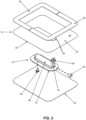
- NPWT bandage 5 generally comprises a membrane (or sheet) 10 and a pump assembly 15.
- membrane 10 is configured to make a fully-sealed chamber around the perimeter of a wound, whereby to define a wound chamber.
- pump assembly 15 is configured to apply a negative pressure to the fully-sealed wound chamber, such that any contaminants and microbes present at the wound site are drawn away from the wound, exudates are drawn out of the wound, and beneficial biological responses are promoted at the wound site.
- pump assembly 15 is designed to provide improved pump efficiency, an automatic pressure indicator for indicating the level of negative pressure created, and an automatic pressure limiter for limiting the level of negative pressure created, as will hereinafter be discussed .
- membrane 10 comprises a flat planar sheet 20 formed out of a flexible, substantially air-impermeable material, e.g., Tegaderm from 3M Company (which has also been known as the Minnesota Mining and Manufacturing Company), so that it can conform to body contours and form a substantially air-tight chamber around the perimeter of a wound (i.e., the wound chamber) .
- Membrane 10 is characterized by a wound-side surface 25 and an atmosphere-side surface 30.
- Membrane 10 is also characterized by an outer perimeter 35 and an inner opening 40.
- An adhesive 45 is preferably disposed on wound- side surface 25 of membrane 10.
- a release liner 50 is preferably disposed on wound-side surface 25 atop adhesive 45 so as to keep adhesive 45 covered until use.
- a removable stiffener 55 is preferably disposed on atmosphere-side surface 30 of membrane 10.
- Removable stiffener 55 serves to facilitate manipulation of NPWT bandage 5 (and particularly membrane 10) during removal of the NPWT bandage from its sterile packaging and during positioning of the NPWT bandage about a wound. Removable stiffener 55 is intended to be removed from membrane 10 once NPWT bandage 5 has been secured about the wound site.
- Removable stiffener 55 may be provided as a single element or, more preferably, removable stiffener 55 is provided as a pair of elements so as to facilitate removal from membrane 10 after NPWT bandage 5 has been secured about the wound site.
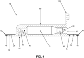
- Pump assembly 15 comprises a pump body 60 having a generally cylindrical shape and comprising a side wall 65 and an inner chamber 70.
- Pump body 60 is formed out of a resilient material, e.g., silicone, such that side wall 65 may be compressed inwardly by the application of an external force (e.g., squeezing by the thumb and forefinger of a user) and will then attempt to return to its original uncompressed state when the external force is removed.
- a pump flange 75 is preferably formed on one side of pump body 60. As will hereinafter be discussed in further detail, pump body 60 extends through inner opening 40 of membrane 10, and the upper surface of pump flange 75 is secured to the wound-side surface 25 of membrane 10 so that pump assembly 15 is secured to, and carried by, membrane 10.
- Pump flange 75 is preferably formed out of a flexible material so that it can conform (to at least a limited extent) to body contours.
- pump body 60 and pump flange 75 are formed integral with one another out of the same material, e.g., silicone.
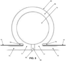
- side wall 65 of pump body 60 and pump flange 75 merge at a neck 77 ( Fig. 5 ) .
- neck 77 has a relatively small width relative to the full diameter of pump body 60, with recesses 78 extending inwardly between membrane 10 and pump body 60, such that pump body 60 is mounted to pump flange 75 but is still free to radially compress/radially expand with minimal interference from pump flange 75.
- a wound-side passageway 80 is formed in pump body 60 and communicates with inner chamber 70. Wound-side passageway 80 opens on the exterior of pump body 60 at a wound-side port 82.
- An atmosphere-side passageway 85 is formed in pump body 60 and also communicates with inner chamber 70. Atmosphere-side passageway 85 opens on the exterior of pump body 60 at an atmosphere-side port 87.
- a wound-side one-way valve 90 is disposed in wound-side passageway 80 and is configured to permit fluid to enter inner chamber 70 through wound-side passageway 80 but to prevent fluid from exiting inner chamber 70 through wound-side passageway 80.
- An atmosphere-side one-way valve 95 is disposed in atmosphere-side passageway 85 and is configured to permit fluid to exit inner chamber 70 through atmosphere-side passageway 85 but to prevent fluid from entering inner chamber 70 through atmosphere-side passageway 85.
- fluid e.g., air, liquid, etc.
- pump body 60 of pump assembly 15 when pump body 60 of pump assembly 15 is manually squeezed (e.g., by applying a compressive force to side wall 65 of pump body 60 with the thumb and forefinger of a user), fluid (e.g., air, liquid, etc.) within inner chamber 70 will be forced out of inner chamber 70 via atmosphere-side passageway 85, and when pump body 60 of pump assembly 15 is thereafter released (e.g., by relaxing the compressive force applied to side wall 65 of pump body 60 by the thumb and forefinger of a user), fluid (e.g., air, liquid, etc.) below wound- side surface 25 of membrane 10 (e.g., air, liquid, etc. within the wound chamber) will be drawn into inner chamber 70 through wound-side passageway 85 as the resilient side wall of the pump body returns to its uncompressed state.
- fluid e.g., air, liquid, etc.
- the present invention's approach of providing a pump assembly utilizing two one-way valves disposed on either side of a deformable pump body with an in-line configuration i.e., wound-side one-way valve 90 and atmosphere-side one-way valve 95 disposed on either side of deformable pump body 60
- wound-side one-way valve 90 and atmosphere-side one-way valve 95 disposed on either side of deformable pump body 60 provides a number of significant advantages which are not achievable with the prior art's approach of providing a deformable pump body utilizing a single one-way valve.
- the present invention's approach of providing a pump assembly utilizing two one-way valves disposed on either side of a deformable pump body with an in-line configuration i.e., wound-side one-way valve 90 and atmosphere-side one-way valve 95 disposed on either side of deformable pump body 60
- wound-side one-way valve 90 and atmosphere-side one-way valve 95 disposed on either side of deformable pump body 60
- the present invention's approach of providing a pump assembly utilizing two one-way valves disposed on either side of a deformable pump body with an in-line configuration i.e., wound-side one-way valve 90 and atmosphere-side one-way valve 95 disposed on either side of deformable pump body 60
- wound-side one-way valve 90 and atmosphere-side one-way valve 95 disposed on either side of deformable pump body 60 allows a greater constant selected maximum negative pressure to be achieved at the wound site than can be achieved at the wound site using a deformable pump body with a single one-way valve (which is reflective of the prior art's approach).
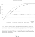
- Fig. 4A shows, for two different size wound chambers (i.e., a 7.5 mL wound chamber and a 15 mL wound chamber), a maximum negative pressure that may be established with (i) a deformable pump body having two one-way valves (with one one-way valve being disposed on either side of the deformable pump body), and (ii) a deformable pump body having a single one-way valve (note: in the comparison shown in Fig. 4A , the volume of the pump chamber of the deformable pump body with 1 one-way valve is the same as the volume of the pump chamber of the deformable pump body with 2 one-way valves).
- Fig. 4A shows that using a deformable pump body having two one-way valves (with one one-way valve being disposed on either side of the deformable pump body) to evacuate the wound chamber lets you establish substantially the same maximum negative pressure in the wound chamber regardless of the size of the wound chamber (i.e., it yields approximately -150.0 mm Hg for a 7.5 mL wound chamber and approximately -150.0 mm Hg for a 15 mL wound chamber), whereas using a deformable pump body having a single one-way valve does not (i.e., it yields approximately -80.0 mm Hg for a 7.5 mL wound chamber and approximately -50.0 mm Hg for a 15 mL wound chamber).
- the NPWT bandage of the present invention allows substantially the same maximum negative pressure to be established at the wound site regardless of the size of the wound chamber, whereas prior art NPWT bandages do not.
- This unique feature of the present invention is clinically significant, inasmuch as (i) it is generally desirable to establish a selected maximum negative pressure at the wound site (e.g., between about 60 mm Hg and about 180 mm Hg) , and (ii) it is generally difficult to know in advance the volume of the wound chamber (e.g., due to variations in medical applications, variations in patient anatomy, etc.) .
- the present invention allows substantially the same maximum negative pressure to be established at the wound site regardless of the size of the wound chamber, the present invention allows the NPWT bandage to be engineered in advance (e.g., at the time of manufacture) to establish a selected maximum negative pressure at the wound site, whereas prior art NPWT bandages do not.
- Fig. 4A shows that using a deformable pump body having two one-way valves (with one one-way valve being disposed on either side of the deformable pump body) to evacuate the wound chamber lets you establish a substantially higher maximum negative pressure in the wound chamber (i.e., it yields approximately - 150.0 mm Hg for a 7.5 mL wound chamber and approximately -150.0 mm Hg for a 15 mL wound chamber) than can be established using a deformable pump body having a single one-way valve (i.e., it yields approximately -80.0 mm Hg for a 7.5 mL wound chamber and approximately -50.0 mm Hg for a 15 mL wound chamber).
- the NPWT bandage of the present invention allows a substantially higher maximum negative pressure to be established at the wound site.
- pump assembly 15 also comprises a removable cap 100.
- Removable cap 100 is configured to selectively close off atmosphere-side passageway 85 to fluid flow when removable cap 100 is inserted into atmosphere-side passageway 85 so as to close off atmosphere-side port 87.
- Pump assembly 15 is mounted to membrane 10 such that pump assembly 15 is carried by membrane 10. More particularly, pump assembly 15 is mounted to membrane 10 by (i) passing pump body 60 of pump assembly 15 through inner opening 40 of membrane 10, (ii) bringing pump flange 75 up against wound-side surface 25 of membrane 10, and then (iii) adhering pump flange 75 to wound-side surface 25 of membrane 10 (e.g., by bonding, gluing, etc.). Note that pump assembly 15 and membrane 10 make a substantially air-tight connection.
- pump body 60 of pump assembly 15 is carefully configured to provide (i) improved pump efficiency, (ii) an automatic pressure indicator for indicating the level of negative pressure created, and (iii) an automatic pressure limiter for limiting the level of negative pressure created, as will hereinafter be discussed.
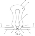
- pump body 60 of pump assembly 15 is specifically configured so that the pump body will abruptly change state between (i) a substantially fully expanded configuration where side wall 65 of pump body 60 and inner chamber 70 of pump body 60 have a substantially circular cross-section (see Fig. 5 ) when the pressure differential between the pressure of the fluid within inner chamber 70 and atmospheric pressure is below a given threshold, and (ii) a substantially fully collapsed configuration where side wall 65 of pump body 60 bows inwardly (see Fig. 6 ) when the pressure differential between the pressure of the fluid within inner chamber 70 and atmospheric pressure exceeds a given threshold.
- pump body 60 of pump assembly 15 when the pressure differential between the pressure of the fluid within inner chamber 70 and atmospheric pressure is below a given threshold, pump body 60 of pump assembly 15 will assume its substantially fully expanded configuration ( Fig. 5 ), and when the pressure differential between the pressure of the fluid within inner chamber 70 and atmospheric pressure is above a given threshold, pump body 60 of pump assembly 15 will assume its substantially fully collapsed configuration ( Fig. 6 ) .
- pump body 60 of pump assembly 15 is configured so that it will abruptly change state between its substantially fully expanded configuration ( Fig. 5 ) and its substantially fully collapsed configuration ( Fig. 6 ) when the pressure differential between the pressure of the fluid within inner chamber 70 and atmospheric pressure crosses the aforementioned given threshold.
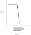
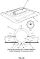
- Fig. 7 is a graph showing the relationship between the diameter of side wall 65 of pump body 60 and the pressure differential between the pressure of a fluid within inner chamber 70 and atmospheric pressure.
- pump assembly 15 is specifically configured to essentially behave as a substantially "binary state" device - it is either substantially fully expanded ( Fig. 5 ) or substantially fully collapsed ( Fig. 6 ) .
- the term “substantially "binary state” device” is intended to refer to a device which is inclined to assume either a substantially fully expanded condition or a substantially fully collapsed condition and, as used herein, the term “substantially “binary state” behavior” is intended to refer to the inclination of a device to assume either a substantially fully expanded condition or a substantially fully collapsed condition .
- the substantially “binary state” behavior of pump body 60 is a consequence of forming the pump body with a side wall 65 having a substantially circular cross-section, which gives the pump body an "over-the-center” deformation characteristic, i.e., the side wall of pump body 60 has a “failure” mode where it abruptly transitions from its substantially fully expanded configuration to its substantially fully collapsed configuration, and has a “restoration” mode where it abruptly transitions from its substantially fully collapsed configuration to its substantially fully expanded configuration.
- pump body 60 has a substantially circular cross-section over substantially its entire circumference, with pump body 60 free to radially compress/radially expand with minimal interference from pump flange 75, so that pump body 60 can exhibit substantially "binary state" behavior.
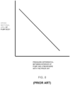
- Fig. 8 is a graph showing the relationship between the diameter of the side wall of a pump body having a dome-like or square configuration and the pressure differential between the pressure of a fluid within an inner chamber of the pump body and atmospheric pressure.
- pump assembly 15 is able to provide improved pump efficiency, an automatic pressure indicator for indicating the level of negative pressure created, and an automatic pressure limiter for limiting the level of negative pressure created.
- pump assembly 15 effectively returns to its substantially fully expanded configuration as long as the pressure differential between the pressure of the fluid within inner chamber 70 and atmospheric pressure is below the given threshold.
- pump assembly 15 returns to its substantially fully expanded configuration between compressions (i.e., squeezes), and hence remains fully efficient as it applies a negative pressure to the wound chamber.
- pump assembly 15 is able to function as an automatic pressure indicator for indicating the level of negative pressure created, i.e., so long as pump body 60 of pump assembly 15 returns to its substantially fully expanded configuration between squeezes, it will be readily apparent to an observer that the pressure within inner chamber 70 (and hence the pressure within the wound chamber) will be less than a given level.
- pump body 60 provides a gradual change of state between an expanded configuration and a collapsed configuration when the pressure differential between the pressure of a fluid within an inner chamber of the pump assembly changes, in which case the pump assembly is not able to function as an automatic pressure indicator for indicating the level of negative pressure created.
- pump assembly 15 is able to function as an automatic pressure limiter for limiting the level of negative pressure created since, as soon as pump body 60 assumes its substantially fully collapsed configuration, pump assembly 15 is no longer able to pump fluid from the wound chamber, essentially deactivating the pump assembly.
- This is in marked contrast to the performance of prior art devices where the pump body provides a gradual change of state between an expanded configuration and a collapsed configuration when the pressure differential between the pressure of a fluid within an inner chamber changes, since the pump assembly is not effectively deactivated at a given pressure differential.
- the pressure differential required to transition pump body 60 between its substantially fully-expanded configuration and its substantially fully-collapsed configuration may be "tuned” (i.e., tailored) to a particular level by varying one or more characteristics of pump body 60, e.g., by forming side wall 65 of pump body 60 out of a material having a particular durometer, by adjusting the thickness of side wall 65 of pump body 60, by adjusting the diameter of inner chamber 70 of pump body 60, etc.
- pump body 60 transitions between its two states at a lower pressure (i.e., where pump body 60 transitions at a negative pressure lower than about 60 mm Hg) , not enough suction is provided at the wound site to effectively draw contaminants and microbes away from the wound site and/or to effectively draw exudates away from the wound site and/or to promote beneficial biological responses at the wound site. It is also believed that where pump body 60 transitions between its two states at a higher pressure (i.e., where pump body 60 transitions at a negative pressure higher than about 180 mm Hg) , the suction provided at the wound site may cause trauma to the tissue (e.g., blistering, capillary leakage, etc.).
- pump body 60 of pump assembly 15 is configured so that it abruptly transitions between its substantially fully expanded configuration and its substantially fully collapsed configuration when the pressure differential between the pressure of the fluid within inner chamber 70 and atmospheric pressure exceeds 80 mm Hg.
- pump assembly 15 returns to its substantially fully expanded configuration between squeezes of the pump body and maintains its pump efficiency as it applies suction to the wound chamber, and as soon as the negative pressure within the wound chamber exceeds 680 mm Hg (assuming atmospheric pressure is 760 mm Hg) , pump assembly 15 will assume its substantially fully collapsed configuration, acting as an automatic pressure indicator to indicate that the level of negative pressure created at the wound site has exceeded 80 mm Hg and automatically deactivating pump assembly 15 so that the level of negative pressure created at the wound site cannot exceed 80 mm Hg.
- NPWT bandage 5 has a low profile.
- pump body 60 of pump assembly 15 is configured to be squeezed between the thumb and forefinger of a user, the compressive force being applied to pump body 60 is applied parallel to the surface of the skin, so that no trauma is applied to the wound during use (i.e., during pumping of pump assembly 15) .
- This is in marked contrast to prior art NPWT bandages which employ a dome-like configuration and require the compressive force to be applied toward the wound.
- NPWT bandage 5 is intended to be used as follows.
- an NPWT bandage 5 is removed from its box.
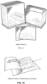
- each individual NPWT bandage 5 is contained in a separate sterile package, with multiple sterile packages contained in a box. See Fig. 9 .
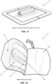
- an NPWT bandage 5 is removed from its sterile package ( Fig. 10 ) so as to be ready for use ( Fig. 11 ).
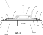
- NPWT bandage 5 In order to apply NPWT bandage 5 to the wound site, release liner 50 is removed from wound-side surface 25 of membrane 10. See Fig. 12 . Then NPWT bandage 5 is positioned against the skin of a patient so that wound-side surface 25 of membrane 10 is positioned against the wound, with adhesive 45 securing NPWT bandage 5 to the skin of the patient, thereby forming a substantially air-tight seal with the skin of the patient about the perimeter of the wound chamber. See Fig. 13 .
- wound-side port 82 of wound-side passageway 80 of pump assembly 15 is open to the wound chamber.
- a layer of gauze (or other absorbent wound dressing) 102 may be placed on the wound site prior to placing NPWT bandage 5 on the skin of the patient, so that the layer of gauze (or other absorbent wound dressing) is interposed between the wound and wound-side passageway 80 of pump assembly 15. As a result, exudate emerging from the wound will be taken up by the gauze (or other absorbent wound dressing) .
- the layer of gauze (or other absorbent wound dressing) 102 may be mounted to (i.e., secured to) the wound-side surface of membrane 10, e.g., such as at the time of manufacture, so that the layer of gauze (or other absorbent wound dressing) 102 is carried to the wound site by NPWT bandage 5 and is applied to the wound at the same time as the NPWT bandage 5.
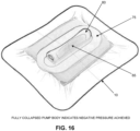
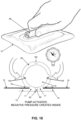
- NPWT bandage 5 may be used to apply negative pressure to the wound chamber. This is done by squeezing side wall 65 of pump body 60 between the thumb and forefinger of a user so as to compress pump body 60 into its substantially fully collapsed configuration, whereby to expel fluid (e.g., air, liquid, etc.) from inner chamber 70 of pump body 60 via atmosphere-side passageway 85 and atmosphere-side one-way valve 95. See Fig. 15 . Note that fluid in inner chamber 70 of pump body 60 is prevented from exiting inner chamber 70 through wound-side passageway 80 due to the presence of wound-side one-way valve 90.
- fluid e.g., air, liquid, etc.
- pump body 60 of pump assembly 15 remains in its substantially fully collapsed configuration even when side wall 65 of pump body 60 is not being manually compressed, pump assembly 15 will have been effectively deactivated, since it will be impossible to continue using the pump assembly with side wall 65 in its substantially fully collapsed configuration.
- removable cap 100 may be used to seal atmosphere-side port 87 of atmosphere-side passageway 85.
- NPWT bandage 5 is left in place on the wound for an appropriate period of time (e.g., a few days) so as to shield the wound from contaminants and microbes during healing, draw exudates out of the wound, and promote beneficial biological responses at the wound site.
- atmosphere-side port 87 of atmosphere-passageway 85 may be unsealed (i.e., by removing removable cap 100) and then pump assembly 15 may be used in the manner discussed above to re establish the desired negative pressure in the wound chamber (i.e., by repeatedly squeezing and releasing side wall 65 of pump body 60) .
- NPWT bandage 5 may be removed from the skin of the patient by simply peeling membrane 10 away from the skin of the patient.
- pump body 60 of pump assembly 15 is preferably specifically configured so that the pump body will abruptly change state between (i) a substantially fully expanded configuration where side wall 65 of pump body 60 and inner chamber 70 of pump body 60 have a substantially circular cross-section (see Fig. 5 ) when the pressure differential between the pressure of the fluid within inner chamber 70 and atmospheric pressure is below a given threshold, and (ii) a substantially fully collapsed configuration where side wall 65 of pump body 60 bows inwardly (see Fig. 6 ) when the pressure differential between the pressure of the fluid within inner chamber 70 and atmospheric pressure exceeds a given threshold.
- this substantially “binary state” behavior of pump body 60 is achieved by forming the pump body with a substantially circular cross- section, which gives the body an "over-the-center” deformation characteristic, i.e., so that the side wall of pump body 60 has a “failure” mode where it abruptly transitions from a substantially fully expanded configuration to a substantially fully collapsed configuration, and has a “restoration” mode where it abruptly transitions from a substantially fully collapsed configuration to a substantially fully expanded configuration. See Fig. 7 .
- pump assembly 15 so that side wall 65 of pump body 60 and pump flange 75 merge at a neck 77 ( Fig.
- pump body 60 has a substantially circular cross-section over substantially its entire circumference, with pump body 60 free to radially compress/radially expand with minimal interference from pump flange 75, so that pump body 60 can exhibit substantially "binary state" behavior.
- pump body 60 can be modified so as to enhance the substantially "binary state” behavior of the pump body.
- notches 105 can be formed in pump body 60 (e.g., at the "9 o'clock", “12 o'clock” and “3 o'clock” positions) so as to enhance the substantially “binary state” behavior of the pump body by further inducing pump body 60 to assume only its substantially fully expanded configuration or its substantially fully collapsed configuration. Note that the more that pump body 60 exhibits true “binary state” behavior, the more that pump efficiency will improve and the better that pump assembly 15 will serve as an automatic pressure indicator and as an automatic pressure limiter.
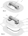
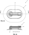
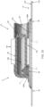
- Figs. 21-25 there is shown another negative pressure wound therapy (NPWT) bandage 5 formed in accordance with the present invention.
- NGWT negative pressure wound therapy
- the NPWT bandage 5 shown in Figs. 21-25 is substantially the same as the NPWT bandage 5 shown in Figs. 1-16 , and the NPWT bandage 5 shown in Figs. 17-20 , except that (i) in the construction shown in Figs. 21-25 , membrane 10 comprises multiple layers which incorporate gauze (or other absorbent wound dressing), and (ii) in the construction shown in Figs. 21-25 , pump assembly 15 has a modified construction and is secured to membrane 10 using a different approach.
- membrane 10 comprises a lower skin-contacting polyurethane layer 110 having a center opening 115, an intermediate foam (or gauze or other absorbent wound dressing) layer 120 for disposition over center opening 115 of lower skin-contacting polyurethane layer 110, and an upper polyurethane layer 125 for disposition over intermediate foam layer 120 and lower skin-contacting polyurethane layer 110.
- upper polyurethane layer 125 is formed out of a substantially air- impermeable material.
- upper polyurethane layer 125 and lower skin-contacting polyurethane layer 110 have the same size outer perimeter, so that upper polyurethane layer 125 does not contact the skin of the patient.
- intermediate foam layer 120 has an outer perimeter which is (i) larger than the perimeter of center opening 115 of lower skin contacting polyurethane layer 110, and (ii) smaller than the outer perimeter of the outer perimeters of lower skin-contacting polyurethane layer 110 and upper polyurethane layer 125. In this way, when NPWT bandage 5 has its center opening 115 of lower skin contacting polyurethane layer 110 positioned over a wound, fluid from the wound can pass through center opening 115 of lower skin-contacting polyurethane layer 110 to reach intermediate foam layer 120.
- adhesive 45 is positioned on the wound side surface of lower skin-contacting polyurethane layer 110 so that a substantially air tight seal may be established by NPWT bandage 5 about the perimeter of a wound (i.e., so as to form the aforementioned wound chamber) .
- An opening 130 is formed in upper polyurethane layer 125, and overlaps center opening 115 of lower skin-contacting polyurethane layer 110, so that wound-side passageway 80 of pump assembly 15 can access fluid (e.g., air, liquid, etc.) within the wound chamber (i.e., via opening 130 in upper polyurethane layer 125, the openings in intermediate foam layer 120, and center opening 115 of lower skin-contacting polyurethane layer 110) for evacuation during pumping of pump assembly 15.
- fluid e.g., air, liquid, etc.
- the pump assembly 15 utilized in the NPWT bandage 5 of Figs. 21-25 is generally similar to the pump assembly 15 described above, except that it comprises a pair of pedestals 135A, 135B for mounting pump assembly 15 to membrane 10. More particularly, pedestal 135A comprises one end of pump body 60 and is adhered (e.g., by an adhesive 137) to the upper surface of membrane 10 (i.e., to the upper surface of upper polyurethane layer 125) so that wound-side passageway 80 and wound-side one-way valve 90 are aligned with opening 130 in upper polyurethane layer 125 (and hence in fluid communication with the wound chamber) .
- pedestal 135A comprises one end of pump body 60 and is adhered (e.g., by an adhesive 137) to the upper surface of membrane 10 (i.e., to the upper surface of upper polyurethane layer 125) so that wound-side passageway 80 and wound-side one-way valve 90 are aligned with opening 130 in upper polyurethane layer 125 (and hence in fluid
- Pedestal 135B comprises the other end of pump body 60 and is adhered (e.g., by an adhesive 138) to the upper surface of membrane 10 (i.e., to the upper surface of upper polyurethane layer 125).
- the intervening portion 140 of pump body 60 sits suspended between pedestal 135A and pedestal 135B, elevated above upper polyurethane layer 125 of membrane 10, so that a space 145 is formed between intervening portion 140 of pump body 60 and upper polyurethane layer 135 of membrane 10.
- intervening portion 140 of pump body 60 can be formed with a true circular cross-section, whereby to enhance the substantially "binary state” behavior of the NPWT bandage. It will be appreciated that pump body 60 may incorporate one or more of the aforementioned notches 105 so as to further enhance the substantially "binary state” behavior of the NPWT bandage.
Landscapes
- Health & Medical Sciences (AREA)
- Heart & Thoracic Surgery (AREA)
- Veterinary Medicine (AREA)
- Engineering & Computer Science (AREA)
- Biomedical Technology (AREA)
- Life Sciences & Earth Sciences (AREA)
- Animal Behavior & Ethology (AREA)
- General Health & Medical Sciences (AREA)
- Public Health (AREA)
- Vascular Medicine (AREA)
- Anesthesiology (AREA)
- Hematology (AREA)
- Pulmonology (AREA)
- Media Introduction/Drainage Providing Device (AREA)
- External Artificial Organs (AREA)
- Materials For Medical Uses (AREA)
- Reciprocating Pumps (AREA)
Claims (24)
- Pansement de thérapie de plaie par pression négative (NPWT) pour appliquer une pression négative à une plaie dans la peau d'un patient, ledit pansement NPWT comprenant :une membrane conçue pour être placée sur une plaie de manière à former une chambre de plaie entre ladite membrane et la plaie, ladite membrane comprenant une surface côté plaie, une surface côté atmosphère et une ouverture s'étendant à travers ladite membrane de ladite surface côté plaie jusqu'à ladite surface côté atmosphère ; etun ensemble pompe porté par ladite membrane, ledit ensemble pompe comprenant :un corps de pompe comprenant une structure de paroi disposée autour d'une chambre de pompe, dans lequel au moins une partie de ladite structure de paroi est formée d'un matériau résilient de telle sorte qu'au moins une partie de ladite structure de paroi peut être comprimée vers l'intérieur par l'application d'une force appliquée parallèlement à la peau du patient ;un passage côté plaie s'étendant à travers ladite structure de paroi et communiquant avec la chambre de plaie à travers ladite ouverture formée dans ladite membrane ;une valve unidirectionnelle côté plaie disposée dans ledit passage côté plaie, ladite valve unidirectionnelle côté plaie étant conçue pour permettre au fluide de s'écouler à travers ledit passage côté plaie de la chambre de plaie vers ladite chambre de pompe, mais pour empêcher le fluide de s'écouler à travers ledit passage côté plaie de ladite chambre de pompe vers la chambre de plaie ;un passage côté atmosphère s'étendant à travers ladite structure de paroi et reliant ladite chambre de pompe à l'atmosphère ; etune valve unidirectionnelle côté atmosphère disposée dans ledit passage côté atmosphère, ladite valve unidirectionnelle côté atmosphère étant conçue pour permettre au fluide de s'écouler à travers ledit passage côté atmosphère de ladite chambre de pompe vers l'atmosphère mais pour empêcher le fluide de s'écouler à travers ledit passage côté atmosphère de l'atmosphère vers ladite chambre de pompe ;de telle sorte que lorsqu'une force de compression est appliquée à ladite structure de paroi dudit corps de pompe dans une direction parallèle à la peau du patient, ladite structure de paroi est comprimée vers l'intérieur et le fluide à l'intérieur de ladite chambre de pompe sera expulsé de ladite chambre de pompe par l'intermédiaire dudit passage côté atmosphère, et lorsque la force de compression appliquée à ladite structure de paroi dudit corps de pompe est ensuite réduite, le fluide à l'intérieur de la chambre de plaie sera aspiré dans ladite chambre de pompe par l'intermédiaire dudit passage côté plaie.
- Pansement NPWT selon la revendication 1 dans lequel ladite membrane comprend une pluralité de couches.
- Pansement NPWT selon la revendication 2 dans lequel ladite membrane comprend une couche sensiblement imperméable à l'air et une couche absorbante, dans lequel ladite couche absorbante est disposée sur le côté plaie de ladite couche sensiblement imperméable à l'air.
- Pansement NPWT selon la revendication 3 comprenant en outre une couche supplémentaire, dans lequel ladite couche absorbante est disposée entre ladite couche sensiblement imperméable à l'air et ladite couche supplémentaire.
- Pansement NPWT selon la revendication 1 dans lequel ledit ensemble pompe comprend une bride reliée audit corps de pompe, dans lequel ladite bride est fixée à ladite surface côté atmosphère de ladite membrane, dans lequel ladite bride est formée d'un seul tenant avec ledit corps de pompe, dans lequel un col est formé entre ledit corps de pompe et ladite bride, et dans lequel en outre une paire d'évidements s'étend vers l'intérieur entre ledit corps de pompe et ladite bride.
- Pansement NPWT selon la revendication 1 dans lequel ledit ensemble pompe est monté sur ladite membrane par une paire de piédestaux, et dans lequel en outre l'un desdits piédestaux comprend ledit passage côté plaie.
- Pansement NPWT selon la revendication 6 dans lequel ledit corps de pompe est suspendu entre ladite paire de piédestaux et espacé de ladite membrane.
- Pansement NPWT selon la revendication 1 dans lequel ladite surface côté plaie de ladite membrane comprend un adhésif.
- Pansement NPWT selon la revendication 8 dans lequel une doublure de séparation est disposée sur ladite surface côté plaie de ladite membrane au-dessus dudit adhésif.
- Pansement NPWT selon la revendication 1 dans lequel un raidisseur amovible est disposé sur ladite surface côté atmosphère de ladite membrane.
- Pansement NPWT selon la revendication 1 dans lequel, lorsque le différentiel de pression entre la pression du fluide à l'intérieur de ladite chambre de pompe et la pression atmosphérique est inférieur à un seuil prédéterminé, ledit corps de pompe dudit ensemble pompe prendra une configuration sensiblement entièrement expansée, et lorsque ledit différentiel de pression entre la pression du fluide à l'intérieur de ladite chambre de pompe et la pression atmosphérique est supérieur audit seuil prédéterminé, ledit corps de pompe dudit ensemble pompe prendra une configuration sensiblement entièrement repliée.
- Pansement NPWT selon la revendication 11 dans lequel ledit corps de pompe change brusquement d'état entre ladite configuration sensiblement totalement expansée et ladite configuration sensiblement totalement repliée, et entre ladite configuration sensiblement totalement repliée et ladite configuration sensiblement totalement expansée, lorsque ledit différentiel de pression franchit ledit seuil prédéterminé de manière à constituer effectivement un dispositif sensiblement à « l'état binaire ».
- Pansement NPWT selon la revendication 11 dans lequel ledit seuil prédéterminé est compris entre environ 60 mm Hg et environ 180 mm Hg.
- Pansement NPWT selon la revendication 11 dans lequel ledit corps de pompe est conçu de manière à fournir une caractéristique de déformation « au-dessus du centre ».
- Pansement NPWT selon la revendication 11 dans lequel ledit corps de pompe comprend une section transversale sensiblement circulaire.
- Pansement NPWT selon la revendication 15 dans lequel ledit corps de pompe comprend une configuration sensiblement cylindrique.
- Pansement NPWT selon la revendication 11 dans lequel (i) ladite structure de paroi dudit corps de pompe et ladite chambre de pompe comprennent une section transversale sensiblement circulaire lorsque ledit différentiel de pression entre la pression du fluide à l'intérieur de ladite chambre de pompe et la pression atmosphérique est inférieur audit seuil prédéterminé, et (ii) ladite structure de paroi dudit corps de pompe s'incurve vers l'intérieur lorsque ledit différentiel de pression entre la pression du fluide à l'intérieur de ladite chambre de pompe et la pression atmosphérique excède ledit seuil prédéterminé.
- Pansement NPWT selon la revendication 11 dans lequel ledit ensemble pompe comprend un capuchon amovible pour fermer sélectivement ledit passage côté atmosphère.
- Pansement NPWT selon la revendication 11 dans lequel ladite surface côté plaie de ladite membrane comprend un adhésif.
- Pansement NPWT selon la revendication 19 dans lequel une doublure de séparation est disposée sur ladite surface côté plaie de ladite membrane au-dessus dudit adhésif.
- Pansement NPWT selon la revendication 11 dans lequel un raidisseur amovible est disposé sur ladite surface côté atmosphère de ladite membrane.
- Pansement NPWT selon la revendication 11 dans lequel ledit ensemble pompe comprend une bride reliée audit corps de pompe, et dans lequel en outre ladite bride est fixée à ladite surface côté plaie de ladite membrane et ledit corps de pompe s'étend à travers ladite ouverture formée dans ladite membrane.
- Pansement NPWT selon la revendication 22 dans lequel ladite bride est formée d'un seul tenant avec ledit corps de pompe.
- Pansement NPWT selon la revendication 11 dans lequel des encoches sont formées dans ladite structure de paroi dudit corps de pompe de manière à faciliter un comportement sensiblement à « l'état binaire ».
Priority Applications (1)
| Application Number | Priority Date | Filing Date | Title |
|---|---|---|---|
| EP24198293.3A EP4559489A3 (fr) | 2017-12-06 | 2018-12-06 | Bandage de thérapie de plaie par pression négative à commande manuelle (npwt) à efficacité de pompe améliorée, indicateur de pression automatique et limiteur de pression automatique |
Applications Claiming Priority (3)
| Application Number | Priority Date | Filing Date | Title |
|---|---|---|---|
| US201762595398P | 2017-12-06 | 2017-12-06 | |
| US201762611227P | 2017-12-28 | 2017-12-28 | |
| PCT/US2018/064178 WO2019113275A1 (fr) | 2017-12-06 | 2018-12-06 | Pansement à pression négative actionné manuellement (npwt) équipé d'une pompe plus efficace, d'un indicateur de pression automatique et d'un limiteur de pression automatique |
Related Child Applications (1)
| Application Number | Title | Priority Date | Filing Date |
|---|---|---|---|
| EP24198293.3A Division EP4559489A3 (fr) | 2017-12-06 | 2018-12-06 | Bandage de thérapie de plaie par pression négative à commande manuelle (npwt) à efficacité de pompe améliorée, indicateur de pression automatique et limiteur de pression automatique |
Publications (3)
| Publication Number | Publication Date |
|---|---|
| EP3720518A1 EP3720518A1 (fr) | 2020-10-14 |
| EP3720518A4 EP3720518A4 (fr) | 2021-09-15 |
| EP3720518B1 true EP3720518B1 (fr) | 2024-09-04 |
Family
ID=66750630
Family Applications (2)
| Application Number | Title | Priority Date | Filing Date |
|---|---|---|---|
| EP18886192.6A Active EP3720518B1 (fr) | 2017-12-06 | 2018-12-06 | Pansement à pression négative actionné manuellement (npwt) équipé d'une pompe plus efficace, d'un indicateur de pression automatique et d'un limiteur de pression automatique |
| EP24198293.3A Pending EP4559489A3 (fr) | 2017-12-06 | 2018-12-06 | Bandage de thérapie de plaie par pression négative à commande manuelle (npwt) à efficacité de pompe améliorée, indicateur de pression automatique et limiteur de pression automatique |
Family Applications After (1)
| Application Number | Title | Priority Date | Filing Date |
|---|---|---|---|
| EP24198293.3A Pending EP4559489A3 (fr) | 2017-12-06 | 2018-12-06 | Bandage de thérapie de plaie par pression négative à commande manuelle (npwt) à efficacité de pompe améliorée, indicateur de pression automatique et limiteur de pression automatique |
Country Status (9)
| Country | Link |
|---|---|
| US (2) | US11839527B2 (fr) |
| EP (2) | EP3720518B1 (fr) |
| JP (2) | JP7424638B2 (fr) |
| KR (1) | KR102649554B1 (fr) |
| CN (1) | CN111432855B (fr) |
| AU (1) | AU2018378653B2 (fr) |
| CA (1) | CA3084180A1 (fr) |
| ES (1) | ES2995038T3 (fr) |
| WO (1) | WO2019113275A1 (fr) |
Families Citing this family (28)
| Publication number | Priority date | Publication date | Assignee | Title |
|---|---|---|---|---|
| GB0808376D0 (en) | 2008-05-08 | 2008-06-18 | Bristol Myers Squibb Co | Wound dressing |
| GB0817796D0 (en) | 2008-09-29 | 2008-11-05 | Convatec Inc | wound dressing |
| GB201020236D0 (en) | 2010-11-30 | 2011-01-12 | Convatec Technologies Inc | A composition for detecting biofilms on viable tissues |
| JP6151186B2 (ja) | 2010-12-08 | 2017-06-21 | コンバテック・テクノロジーズ・インコーポレイテッドConvatec Technologies Inc | 創傷滲出液システム付属装置 |
| CN103347561B (zh) | 2010-12-08 | 2016-09-07 | 康沃特克科技公司 | 用于评估伤口分泌液的集成系统 |
| JP5833134B2 (ja) | 2010-12-08 | 2015-12-16 | コンバテック・テクノロジーズ・インコーポレイテッドConvatec Technologies Inc | 創傷部位から滲出液を除去するための方法およびシステム |
| GB201115182D0 (en) | 2011-09-02 | 2011-10-19 | Trio Healthcare Ltd | Skin contact material |
| GB2497406A (en) | 2011-11-29 | 2013-06-12 | Webtec Converting Llc | Dressing with a perforated binder layer |
| WO2014096843A2 (fr) | 2012-12-20 | 2014-06-26 | Convatec Technologies Inc. | Traitement de fibres cellulosiques chimiquement modifiées |
| GB2543544A (en) | 2015-10-21 | 2017-04-26 | Brightwake Ltd | Wound dressing |
| CA3019436A1 (fr) | 2016-03-30 | 2017-10-05 | Qualizyme Diagnostics Gmbh & Co Kg | Detection d'une infection microbienne dans les plaies |
| SG11201808488XA (en) | 2016-03-30 | 2018-10-30 | Convatec Technologies Inc | Detecting microbial infections in wounds |
| GB201608099D0 (en) | 2016-05-09 | 2016-06-22 | Convatec Technologies Inc | Negative pressure wound dressing |
| EP3871645B1 (fr) | 2016-07-08 | 2022-05-04 | ConvaTec Technologies Inc. | Système de pression flexible négative |
| ES2912094T3 (es) | 2016-07-08 | 2022-05-24 | Convatec Technologies Inc | Detección de flujo de fluidos |
| JP2019525799A (ja) | 2016-07-08 | 2019-09-12 | コンバテック・テクノロジーズ・インコーポレイテッドConvatec Technologies Inc | 流体収集装置 |
| EP3585453B1 (fr) * | 2017-02-22 | 2023-05-17 | Cornell University | Pansement à vide mécanique de gestion, protection et aspiration mécaniques de petites plaies incisionnelles |
| EP4360666A3 (fr) | 2017-11-16 | 2024-05-08 | ConvaTec Limited | Appareil de collecte de fluide |
| US20220378623A1 (en) * | 2017-12-06 | 2022-12-01 | Guard Medical Sas | Negative pressure wound therapy (npwt) bandage |
| CN111432855B (zh) * | 2017-12-06 | 2024-02-23 | 康奈尔大学 | 具有提高的泵效率、自动压力指示器和自动压力限制器的手动操作的负压伤口治疗(npwt)绷带 |
| US20230049136A1 (en) * | 2017-12-06 | 2023-02-16 | Guard Medical Sas | Negative pressure wound therapy (npwt) bandage |
| SG11202112292QA (en) | 2019-06-03 | 2021-12-30 | Convatec Ltd | Methods and devices to disrupt and contain pathogens |
| KR20220084311A (ko) * | 2019-10-22 | 2022-06-21 | 가드 메디컬 에스에이에스 | 음압 상처 치료(npwt) 붕대 |
| US11331221B2 (en) | 2019-12-27 | 2022-05-17 | Convatec Limited | Negative pressure wound dressing |
| US11771819B2 (en) | 2019-12-27 | 2023-10-03 | Convatec Limited | Low profile filter devices suitable for use in negative pressure wound therapy systems |
| JP2023551218A (ja) * | 2020-11-24 | 2023-12-07 | アロア・バイオサージェリー・リミテッド | 創傷を処置するためのシステム |
| CN117715666A (zh) | 2021-07-23 | 2024-03-15 | 康沃特克有限公司 | 可选择性地配置的伤口敷料 |
| BR102022015836A2 (pt) | 2022-08-10 | 2024-02-20 | Blue Hands Servicos Medicos S/S | Dispositivo para terapia com pressão negativa em pele ou ferimento, processo de fabricação do mesmo e uso de terapia com pressão negativa |
Citations (1)
| Publication number | Priority date | Publication date | Assignee | Title |
|---|---|---|---|---|
| US3486504A (en) * | 1967-11-20 | 1969-12-30 | Lawthan M Austin Jr | Device for applying dressing,medication and suction |
Family Cites Families (174)
| Publication number | Priority date | Publication date | Assignee | Title |
|---|---|---|---|---|
| US3874387A (en) | 1972-07-05 | 1975-04-01 | Pasquale P Barbieri | Valved hemostatic pressure cap |
| US3938514A (en) * | 1974-07-18 | 1976-02-17 | Boucher Lionel J | Bladder wash method and apparatus |
| US4073294A (en) | 1975-07-23 | 1978-02-14 | Medical Development Corporation | Negative pressure drainage vessel |
| US4465062A (en) | 1982-05-14 | 1984-08-14 | Gina Versaggi | Noninvasive seal for a sucking chest wound |
| US4997438A (en) | 1989-04-14 | 1991-03-05 | Constance Crane Langmann | Pressure applicator for thoracic wounds |
| AU651189B2 (en) | 1991-04-17 | 1994-07-14 | Regents Of The University Of California, The | Improved devices and methods for external chest compression |
| US5263922A (en) | 1991-08-26 | 1993-11-23 | Plasco, Inc. | Valved bandage |
| US5645081A (en) | 1991-11-14 | 1997-07-08 | Wake Forest University | Method of treating tissue damage and apparatus for same |
| US7198046B1 (en) | 1991-11-14 | 2007-04-03 | Wake Forest University Health Sciences | Wound treatment employing reduced pressure |
| US5636643A (en) | 1991-11-14 | 1997-06-10 | Wake Forest University | Wound treatment employing reduced pressure |
| US5589256A (en) | 1992-08-17 | 1996-12-31 | Weyerhaeuser Company | Particle binders that enhance fiber densification |
| US5478333A (en) | 1994-03-04 | 1995-12-26 | Asherman, Jr.; Richard E. | Medical dressing for treating open chest injuries |
| US5549584A (en) | 1994-02-14 | 1996-08-27 | The Kendall Company | Apparatus for removing fluid from a wound |
| US5562107A (en) | 1995-09-27 | 1996-10-08 | Hollister Incorporated | Reclosable wound cover |
| US5788463A (en) | 1995-12-22 | 1998-08-04 | Chan; Kwan-Ho | Manual vacuum producing system having pressure indicator |
| US5848993A (en) * | 1997-08-07 | 1998-12-15 | Deroyal Industries, Inc. | Bulb syringe providing for visual observation of contents thereof and for enhanced deflation/inflation control |
| GB9719520D0 (en) * | 1997-09-12 | 1997-11-19 | Kci Medical Ltd | Surgical drape and suction heads for wound treatment |
| US20040033750A1 (en) | 1998-06-12 | 2004-02-19 | Everett Rob D | Layered absorbent structure with a heterogeneous layer region |
| US6458109B1 (en) | 1998-08-07 | 2002-10-01 | Hill-Rom Services, Inc. | Wound treatment apparatus |
| US7694821B1 (en) * | 1999-06-04 | 2010-04-13 | Medtronic Ps Medical, Inc. | Subdural evacuating port system |
| CA2397614C (fr) | 1999-12-09 | 2009-11-10 | Waikatolink Limited | Pansement a base de miel |
| GB0011202D0 (en) | 2000-05-09 | 2000-06-28 | Kci Licensing Inc | Abdominal wound dressing |
| US6431212B1 (en) | 2000-05-24 | 2002-08-13 | Jon W. Hayenga | Valve for use in microfluidic structures |
| US7041868B2 (en) | 2000-12-29 | 2006-05-09 | Kimberly-Clark Worldwide, Inc. | Bioabsorbable wound dressing |
| US7763769B2 (en) | 2001-02-16 | 2010-07-27 | Kci Licensing, Inc. | Biocompatible wound dressing |
| US7070584B2 (en) | 2001-02-20 | 2006-07-04 | Kci Licensing, Inc. | Biocompatible wound dressing |
| SE521684C2 (sv) | 2001-04-30 | 2003-11-25 | Micvac Ab | Återförslutningsbar envägsventil för livsmedelsförpackning |
| EP1487389B1 (fr) | 2002-02-28 | 2011-10-05 | KCI Medical Resources | Acces d'un catheter exterieur a un pansement sous vide |
| DE20207356U1 (de) | 2002-05-08 | 2003-06-12 | Riesinger, Birgit, 48346 Ostbevern | Absorptionskörper zum Anschluß an Haut- und Schleimhautoberflächen |
| US6951553B2 (en) | 2002-12-31 | 2005-10-04 | Kci Licensing, Inc | Tissue closure treatment system and method with externally-applied patient interface |
| US7976519B2 (en) | 2002-12-31 | 2011-07-12 | Kci Licensing, Inc. | Externally-applied patient interface system and method |
| US7674039B2 (en) | 2003-02-19 | 2010-03-09 | Illinois Tool Works Inc. | Reclosable vacuum storage bag having flat resealable means |
| US7942866B2 (en) | 2003-08-28 | 2011-05-17 | Boehringer Technologies, L.P. | Device for treating a wound |
| US7361184B2 (en) | 2003-09-08 | 2008-04-22 | Joshi Ashok V | Device and method for wound therapy |
| GB0325129D0 (en) | 2003-10-28 | 2003-12-03 | Smith & Nephew | Apparatus in situ |
| DE602004016022D1 (de) | 2003-10-30 | 2008-10-02 | Mcneil Ppc Inc | Zusammengesetzte materialien aus metall beladenen abgeblätterten nanoteilchen |
| US10058642B2 (en) | 2004-04-05 | 2018-08-28 | Bluesky Medical Group Incorporated | Reduced pressure treatment system |
| US7790945B1 (en) | 2004-04-05 | 2010-09-07 | Kci Licensing, Inc. | Wound dressing with absorption and suction capabilities |
| US7708724B2 (en) | 2004-04-05 | 2010-05-04 | Blue Sky Medical Group Incorporated | Reduced pressure wound cupping treatment system |
| US8062272B2 (en) | 2004-05-21 | 2011-11-22 | Bluesky Medical Group Incorporated | Flexible reduced pressure treatment appliance |
| US7909805B2 (en) | 2004-04-05 | 2011-03-22 | Bluesky Medical Group Incorporated | Flexible reduced pressure treatment appliance |
| US7534039B2 (en) | 2004-07-22 | 2009-05-19 | Sunbeam Products, Inc. | Vacuum packaging films patterned with protruding cavernous structures |
| US7290660B2 (en) | 2004-07-23 | 2007-11-06 | Tilman Paul A | Storage system having a disposable vacuum bag |
| EP1922095A2 (fr) | 2005-09-07 | 2008-05-21 | Tyco Healthcare Group LP | Pansement de plaies avec un reservoir a vide |
| BRPI0616591A2 (pt) | 2005-09-07 | 2011-06-28 | Tyco Healthcare | aparelho de curativo de ferimento independente |
| EP1922045B1 (fr) | 2005-09-07 | 2012-11-07 | Tyco Healthcare Group LP | Pansement pour plaies autonome muni d'une micropompe |
| DE202005019670U1 (de) | 2005-12-14 | 2006-04-27 | Riesinger, Birgit | Wundbehandlungsvorrichtung mit elastisch verformbarem Unterdruckerzeugungselement |
| US7779625B2 (en) | 2006-05-11 | 2010-08-24 | Kalypto Medical, Inc. | Device and method for wound therapy |
| US20080003274A1 (en) | 2006-06-28 | 2008-01-03 | Kaiser Daniel E | Decompressive thermogenic bandage |
| US8212100B2 (en) | 2006-08-04 | 2012-07-03 | Quandra Innovations International, LLC | Apparatus, system, and method for protecting and treating a traumatic wound |
| WO2008034897A1 (fr) * | 2006-09-22 | 2008-03-27 | Coloplast A/S | Enduit de pellicule |
| EP2081528B1 (fr) | 2006-09-26 | 2018-11-14 | T.J. Smith & Nephew, Limited | Pansement de type quadrillé |
| US9820888B2 (en) | 2006-09-26 | 2017-11-21 | Smith & Nephew, Inc. | Wound dressing |
| CN102626529B (zh) | 2006-10-13 | 2015-10-28 | 凯希特许有限公司 | 用于对低严重性伤口提供治疗的、具有手动启动泵的减压输送系统 |
| US8771243B2 (en) * | 2007-02-01 | 2014-07-08 | University Of Cincinnati | Wound treatment system |
| CA2674036C (fr) | 2007-02-09 | 2017-01-10 | Kci Licensing, Inc. | Systeme et procede destines a appliquer une pression reduite sur un site tissulaire |
| WO2008112304A1 (fr) | 2007-03-14 | 2008-09-18 | The Board Of Trustees Of The Leland Stanford Junior University | Dispositifs et procédés pour l'application d'une thérapie par pression réduite |
| CA2687406A1 (fr) | 2007-05-07 | 2008-11-13 | Carmeli Adahan | Systeme d'aspiration |
| JP5642539B2 (ja) | 2007-05-24 | 2014-12-17 | アプライド ティッシュ テクノロジーズ リミテッド ライアビリティ カンパニー | 負圧を使用する創傷治療デバイス |
| US7874731B2 (en) | 2007-06-15 | 2011-01-25 | S.C. Johnson Home Storage, Inc. | Valve for a recloseable container |
| SE531259C2 (sv) | 2007-06-27 | 2009-02-03 | Moelnlycke Health Care Ab | Anordning för behandling av sår med reducerat tryck |
| US8246590B2 (en) | 2007-10-11 | 2012-08-21 | Spiracur, Inc. | Closed incision negative pressure wound therapy device and methods of use |
| ES2776709T3 (es) | 2007-11-21 | 2020-07-31 | Smith & Nephew | Apósito para heridas |
| MX2010005553A (es) | 2007-11-21 | 2010-06-01 | Smith & Nephew | Aposito para heridas. |
| GB0723872D0 (en) | 2007-12-06 | 2008-01-16 | Smith & Nephew | Apparatus for topical negative pressure therapy |
| CA2711620A1 (fr) | 2008-01-08 | 2009-07-16 | Bluesky Medical Group Inc. | Traitement durable de blessures par pression negative variable et procede pour son controle |
| AU2009214439B2 (en) | 2008-02-14 | 2014-09-25 | Solventum Intellectual Properties Company | Devices and methods for treatment of damaged tissue |
| US8449508B2 (en) * | 2008-03-05 | 2013-05-28 | Kci Licensing, Inc. | Dressing and method for applying reduced pressure to and collecting and storing fluid from a tissue site |
| US8298200B2 (en) | 2009-06-01 | 2012-10-30 | Tyco Healthcare Group Lp | System for providing continual drainage in negative pressure wound therapy |
| US9033942B2 (en) | 2008-03-07 | 2015-05-19 | Smith & Nephew, Inc. | Wound dressing port and associated wound dressing |
| BRPI0906527A2 (pt) | 2008-04-04 | 2016-09-06 | 3Mm Innovative Properties Company | aparelho para aplicação de bandagens em ferimentos e bandagem médica |
| EP2265234A4 (fr) | 2008-04-04 | 2011-08-31 | 3M Innovative Properties Co | Pansements médicaux ayant une soupape et kits contenant ceux-ci |
| CN201200434Y (zh) | 2008-04-10 | 2009-03-04 | 叶松 | 负压创口贴 |
| KR101192947B1 (ko) | 2008-05-30 | 2012-10-18 | 케이씨아이 라이센싱 인코포레이티드 | 가슴 조직에서 사용되는 감압,압축 장치 및 방법 |
| US20200113741A1 (en) | 2008-05-30 | 2020-04-16 | Kci Licensing, Inc. | Dressing with tissue viewing capability |
| US8257326B2 (en) * | 2008-06-30 | 2012-09-04 | Tyco Healthcare Group Lp | Apparatus for enhancing wound healing |
| EP2318065B1 (fr) | 2008-08-05 | 2018-09-26 | Mölnlycke Health Care AB | Composant de fixation solide d'un dispositif médical à la peau |
| WO2010053870A1 (fr) | 2008-11-07 | 2010-05-14 | Kci Licensing, Inc. | Pansement et systèmes de traitement de plaies à pression réduite |
| EP3614114A1 (fr) | 2008-11-25 | 2020-02-26 | KCI Licensing, Inc. | Dispositif d'application de pression réduite sur des surfaces corporelles |
| US8361043B2 (en) | 2009-01-07 | 2013-01-29 | Spiracur Inc. | Reduced pressure therapy of the sacral region |
| US8246591B2 (en) * | 2009-01-23 | 2012-08-21 | Tyco Healthcare Group Lp | Flanged connector for wound therapy |
| GB0902816D0 (en) | 2009-02-19 | 2009-04-08 | Smith & Nephew | Fluid communication path |
| EP2419157A4 (fr) * | 2009-04-17 | 2018-01-03 | Kalypto Medical, Inc. | Dispositif de traitement de plaie à pression négative |
| US20110196321A1 (en) | 2009-06-10 | 2011-08-11 | Tyco Healthcare Group Lp | Fluid Collection Canister Including Canister Top with Filter Membrane and Negative Pressure Wound Therapy Systems Including Same |
| US20100324516A1 (en) | 2009-06-18 | 2010-12-23 | Tyco Healthcare Group Lp | Apparatus for Vacuum Bridging and/or Exudate Collection |
| US8529526B2 (en) | 2009-10-20 | 2013-09-10 | Kci Licensing, Inc. | Dressing reduced-pressure indicators, systems, and methods |
| DK2515961T3 (da) | 2009-12-22 | 2019-07-15 | Smith & Nephew Inc | Apparatuses and methods for negative pressure wound therapy |
| DE102009060596A1 (de) | 2009-12-23 | 2011-06-30 | Paul Hartmann Aktiengesellschaft, 89522 | Anschlussvorrichtung zur Verwendung bei der Unterdruckbehandlung von Wunden |
| US8430867B2 (en) | 2010-03-12 | 2013-04-30 | Kci Licensing, Inc. | Reduced-pressure dressing connection pads, systems, and methods |
| US8821458B2 (en) | 2010-04-16 | 2014-09-02 | Kci Licensing, Inc. | Evaporative body-fluid containers and methods |
| US9061095B2 (en) | 2010-04-27 | 2015-06-23 | Smith & Nephew Plc | Wound dressing and method of use |
| WO2011162862A1 (fr) | 2010-06-23 | 2011-12-29 | Convatec Technologies Inc. | Pansement pour plaies |
| US8795257B2 (en) | 2010-07-19 | 2014-08-05 | Kci Licensing, Inc. | Systems and methods for electrically detecting the presence of exudate in dressings |
| WO2012019147A1 (fr) | 2010-08-06 | 2012-02-09 | Kci Licensing, Inc. | Système et méthode de traitement des tissus chez un patient utilisant un générateur thermoélectrique |
| US8753322B2 (en) | 2010-08-10 | 2014-06-17 | Spiracur Inc. | Controlled negative pressure apparatus and alarm mechanism |
| US8795246B2 (en) | 2010-08-10 | 2014-08-05 | Spiracur Inc. | Alarm system |
| TWI411427B (zh) | 2010-08-13 | 2013-10-11 | Wei Hua Lu | 負壓照料裝置 |
| GB201015656D0 (en) | 2010-09-20 | 2010-10-27 | Smith & Nephew | Pressure control apparatus |
| CN103200974B (zh) | 2010-09-20 | 2018-04-27 | 史密夫及内修公开有限公司 | 负压装置 |
| US20120109034A1 (en) | 2010-10-27 | 2012-05-03 | Kci Licensing, Inc. | Interactive, wireless reduced-pressure dressings, methods, and systems |
| JP5833134B2 (ja) | 2010-12-08 | 2015-12-16 | コンバテック・テクノロジーズ・インコーポレイテッドConvatec Technologies Inc | 創傷部位から滲出液を除去するための方法およびシステム |
| EP2654821B1 (fr) | 2010-12-22 | 2019-05-08 | Smith & Nephew, Inc. | Appareils pour thérapie de plaie à pression négative |
| US8439894B1 (en) * | 2011-03-07 | 2013-05-14 | Larry W. Miller | Negative pressure bandage with internal storage chamber |
| WO2012151359A1 (fr) | 2011-05-03 | 2012-11-08 | Avery Dennison Corporation | Appareil de thérapie de traitement des plaies par pression négative comprenant une valve anti-reflux et procédés associés |
| AU2012282287B2 (en) | 2011-07-14 | 2017-06-01 | Smith & Nephew Plc | Wound dressing and method of treatment |
| WO2013013080A1 (fr) | 2011-07-20 | 2013-01-24 | Sapheon, Inc. | Visualisation échographique améliorée de dispositifs intravasculaires |
| US20130046223A1 (en) | 2011-08-15 | 2013-02-21 | Stephen Schrammel | Long Term Wound Dressing |
| IN2014CN02072A (fr) | 2011-08-22 | 2015-05-29 | Microlin Llc | |
| JP6083762B2 (ja) | 2011-08-31 | 2017-02-22 | ケーシーアイ ライセンシング インコーポレイテッド | 体液と共に使用するインライン式貯蔵パウチ |
| US9561134B2 (en) | 2011-09-14 | 2017-02-07 | Matthew T. Scholz | Positive pressure medical dressings with valve and kits containing same |
| DE102011055782A1 (de) | 2011-11-28 | 2013-05-29 | Birgit Riesinger | Wundpflegevorrichtung zur behandlung von wunden mittels atmosphärischem unterdruck |
| AU2013209432B2 (en) | 2012-01-18 | 2016-11-17 | Worldwide Innovative Healthcare, Inc. | Modifiable occlusive skin dressing |
| US9234518B2 (en) | 2012-02-10 | 2016-01-12 | Kci Licensing, Inc. | Systems and methods for monitoring reduced pressure supplied by a disc pump system |
| EP2636417B1 (fr) | 2012-03-05 | 2017-04-26 | Lohmann & Rauscher GmbH | Agencement de pansement de plaies et dispositif de revêtement correspondant |
| MX2014011030A (es) | 2012-03-12 | 2015-03-20 | Smith & Nephew | Aparato y metodos de presion reducida. |
| US20180021178A1 (en) | 2012-03-28 | 2018-01-25 | Kci Licensing, Inc. | Reduced-Pressure Systems, Dressings, Pump Assemblies And Methods |
| CN104168865B (zh) | 2012-03-28 | 2016-10-26 | 凯希特许有限公司 | 协助电子的和临床的零部件分离的减压系统、敷件、和方法 |
| US9427505B2 (en) | 2012-05-15 | 2016-08-30 | Smith & Nephew Plc | Negative pressure wound therapy apparatus |
| CN107095739B (zh) | 2012-05-23 | 2020-11-13 | 史密夫及内修公开有限公司 | 用于负压伤口治疗的装置和方法 |
| US9271937B2 (en) | 2012-05-31 | 2016-03-01 | Covidien Lp | Oxidized cellulose microspheres |
| US9138489B2 (en) | 2012-05-31 | 2015-09-22 | Covidien Lp | Oxidized cellulose miczrospheres including visualization agents |
| US10040871B2 (en) | 2012-06-28 | 2018-08-07 | Covidien Lp | Medical devices based on oxidized cellulose |
| WO2014039557A1 (fr) * | 2012-09-04 | 2014-03-13 | Integrated Healing Technologies | Pansement de plaie |
| EP2916786B1 (fr) | 2012-11-12 | 2018-03-21 | KCI Licensing, Inc. | Pansements et fermetures de plaies appliqués de manière externe |
| US20140171920A1 (en) | 2012-12-15 | 2014-06-19 | Christopher Scott Smith | Wound dressing apparatuses and methods thereof |
| JP2016508056A (ja) | 2013-01-03 | 2016-03-17 | ケーシーアイ ライセンシング インコーポレイテッド | 再チャージ式陰圧閉鎖療法 |
| GB201317742D0 (en) | 2013-10-08 | 2013-11-20 | Smith & Nephew | Ph indicator dressing |
| TW201433275A (zh) | 2013-02-22 | 2014-09-01 | Universal Trim Supply Co Ltd | 簡易式充氣閥構造 |
| WO2014158526A1 (fr) | 2013-03-14 | 2014-10-02 | Kci Licensing, Inc. | Traitement par pression négative à capacité de profil dynamique |
| EP2968648B1 (fr) | 2013-03-15 | 2020-12-23 | Smith & Nephew plc | Pansement de plaie et procédé de traitement |
| JP6441891B2 (ja) | 2013-03-15 | 2018-12-19 | スパイラキュア インコーポレイテッド | 一体型弁を有する真空カートリッジ |
| US10413566B2 (en) | 2013-03-15 | 2019-09-17 | Covidien Lp | Thixotropic oxidized cellulose solutions and medical applications thereof |
| US10335322B2 (en) | 2013-08-26 | 2019-07-02 | Lightside Md, Llc | Adhesive support devices and methods of making and using them |
| US10292871B2 (en) | 2013-11-13 | 2019-05-21 | 3M Innovative Properties Company | Wound care system with a mat of capillary membranes |
| US9883856B2 (en) | 2014-01-09 | 2018-02-06 | Covidien Lp | Systems and methods for treatment of perforator veins for venous insufficiency |
| WO2015123340A1 (fr) | 2014-02-11 | 2015-08-20 | Spiracur Inc. | Procédés et dispositifs pour l'application d'une thérapie par pression négative sur une incision fermée |
| EP3122301B1 (fr) | 2014-03-28 | 2018-04-25 | 3M Innovative Properties Company | Article et procédé de thérapie par dépression pour plaies |
| CN106535842B (zh) | 2014-06-05 | 2020-07-17 | 凯希特许有限公司 | 具有流体获取和分配特征的敷料 |
| EP3157484B1 (fr) | 2014-06-18 | 2020-02-26 | Smith & Nephew plc | Pansement |
| WO2016006457A1 (fr) | 2014-07-07 | 2016-01-14 | 株式会社村田製作所 | Dispositif thérapeutique de fermeture de plaies à pression négative |
| US10449152B2 (en) | 2014-09-26 | 2019-10-22 | Covidien Lp | Drug loaded microspheres for post-operative chronic pain |
| AU2015360377B2 (en) * | 2014-12-10 | 2020-09-24 | Worldwide Innovative Healthcare, Inc. | Unbacked and modifiable tapes and skin dressings |
| AU2015370583B2 (en) | 2014-12-22 | 2020-08-20 | Smith & Nephew Plc | Negative pressure wound therapy apparatus and methods |
| FR3031097B1 (fr) | 2014-12-30 | 2017-02-10 | Commissariat Energie Atomique | Pompe surfacique et pansement comportant une pompe surfacique |
| EP3240580B1 (fr) | 2014-12-30 | 2020-04-15 | 3M Innovative Properties Company | Pansement à pression négative doté d'une couche de scellement adhésive et absorbante |
| US20160206792A1 (en) * | 2015-01-16 | 2016-07-21 | George Medical, Llc | Self adhering suction port pad securement device for use with a negative pressure wound healing drape or dressing |
| EP3574877B1 (fr) | 2015-05-08 | 2022-08-17 | 3M Innovative Properties Company | Pansement à faible acuité doté d'une pompe intégrée |
| EP3093032B1 (fr) | 2015-05-11 | 2018-09-19 | 3M Innovative Properties Company | Dispositif et procédé destinés à la production de sérum |
| EP3092987A1 (fr) | 2015-05-11 | 2016-11-16 | 3M Innovative Properties Company | Système de traitement de plaies à l'aide de sérum |
| WO2016184913A1 (fr) | 2015-05-18 | 2016-11-24 | Smith & Nephew Plc | Appareil de traitement des plaies par pression négative et méthodes associées |
| WO2016184918A1 (fr) | 2015-05-18 | 2016-11-24 | Smith & Nephew Plc | Systèmes de pompe thermo-assistés pour utilisation dans le traitement des plaies par pression négative |
| WO2016188968A1 (fr) | 2015-05-26 | 2016-12-01 | Smith & Nephew Plc | Source de pression négative compressible et procédés d'utilisation |
| WO2017003937A1 (fr) | 2015-06-29 | 2017-01-05 | Kci Licensing, Inc. | Appareil pour l'irrigation à pression négative |
| WO2017040074A1 (fr) | 2015-08-31 | 2017-03-09 | 3M Innovative Properties Company | Pansements de traitement des plaies à pression négative comprenant des adhésifs (méth)acrylate sensibles à la pression présentant une meilleure adhérence à des surfaces humides |
| WO2017053384A1 (fr) | 2015-09-21 | 2017-03-30 | Brigham And Women's Hospital, Inc. | Système et procédé de traitement des plaies par gradient |
| EP3377013B1 (fr) | 2015-11-20 | 2020-02-26 | KCI Licensing, Inc. | Système médical possédant un pont souple de stockage de liquide |
| US10575991B2 (en) | 2015-12-15 | 2020-03-03 | University Of Massachusetts | Negative pressure wound closure devices and methods |
| CN105457110A (zh) | 2016-01-08 | 2016-04-06 | 昆山韦睿医疗科技有限公司 | 一种手动负压治疗设备 |
| US20170209312A1 (en) | 2016-01-22 | 2017-07-27 | Covidien Lp | Absorbent articles including silicone |
| TWI595902B (zh) | 2016-05-10 | 2017-08-21 | 明基材料股份有限公司 | 攜帶型負壓裝置 |
| EP3454806B1 (fr) | 2016-05-13 | 2023-06-21 | Eksteen, Ehren Cronje | Traitement de plaies |
| CN109414349A (zh) | 2016-06-27 | 2019-03-01 | 3M创新有限公司 | 具有特征部的负压伤口治疗制品 |
| GB2553536A (en) | 2016-09-07 | 2018-03-14 | Univ Strathclyde | Improvements in or relating to blood salvage and autotransfusion |
| CN110072497B (zh) | 2016-11-11 | 2020-08-11 | 3M创新有限公司 | 可修剪的适形伤口敷料 |
| JP7121050B2 (ja) | 2017-05-09 | 2022-08-17 | スミス アンド ネフュー ピーエルシー | 陰圧創傷療法システムの冗長制御 |
| WO2018210693A1 (fr) | 2017-05-15 | 2018-11-22 | Smith & Nephew Plc | Système de thérapie de plaie par pression négative utilisant un grossissement vidéo eulérien |
| EP3960138B8 (fr) | 2017-05-16 | 2024-04-03 | Solventum Intellectual Properties Company | Système de pansement absorbant à pression négative destiné à être utilisé pour des plaies mammaires post-chirurgicales |
| EP3638332A1 (fr) | 2017-06-14 | 2020-04-22 | Smith & Nephew, Inc | Gestion de l'élimination de liquide et maîtrise de la fermeture d'une plaie dans un traitement de plaie |
| WO2019007874A1 (fr) | 2017-07-07 | 2019-01-10 | Smith & Nephew Plc | Système de traitement de plaie et pansement pour administrer de l'oxygène à une plaie |
| GB201718014D0 (en) | 2017-11-01 | 2017-12-13 | Smith & Nephew | Dressing for negative pressure wound therapy with filter |
| CN111432855B (zh) * | 2017-12-06 | 2024-02-23 | 康奈尔大学 | 具有提高的泵效率、自动压力指示器和自动压力限制器的手动操作的负压伤口治疗(npwt)绷带 |
| EP3866737A1 (fr) | 2018-10-17 | 2021-08-25 | KCI Licensing, Inc. | Pansement à décoller et à placer comprenant une couche de contact à cellules fermées |
| EP3874904B1 (fr) | 2018-10-31 | 2024-06-26 | Solventum Intellectual Properties Company | Réseau pair à pair de courte portée pour dispositifs de traitement de plaie par pression négative |
| WO2020205448A1 (fr) | 2019-03-29 | 2020-10-08 | Kci Licensing, Inc. | Pansement à pompe intégrée et actionneur de pompe couplé de manière amovible |
-
2018
- 2018-12-06 CN CN201880078990.7A patent/CN111432855B/zh active Active
- 2018-12-06 US US16/768,481 patent/US11839527B2/en active Active
- 2018-12-06 AU AU2018378653A patent/AU2018378653B2/en active Active
- 2018-12-06 WO PCT/US2018/064178 patent/WO2019113275A1/fr not_active Ceased
- 2018-12-06 EP EP18886192.6A patent/EP3720518B1/fr active Active
- 2018-12-06 CA CA3084180A patent/CA3084180A1/fr active Pending
- 2018-12-06 ES ES18886192T patent/ES2995038T3/es active Active
- 2018-12-06 EP EP24198293.3A patent/EP4559489A3/fr active Pending
- 2018-12-06 JP JP2020529125A patent/JP7424638B2/ja active Active
- 2018-12-06 KR KR1020207014704A patent/KR102649554B1/ko active Active
-
2023
- 2023-12-12 US US18/536,475 patent/US20240261154A1/en active Pending
-
2024
- 2024-01-11 JP JP2024002272A patent/JP7665233B2/ja active Active
Patent Citations (1)
| Publication number | Priority date | Publication date | Assignee | Title |
|---|---|---|---|---|
| US3486504A (en) * | 1967-11-20 | 1969-12-30 | Lawthan M Austin Jr | Device for applying dressing,medication and suction |
Also Published As
| Publication number | Publication date |
|---|---|
| KR102649554B1 (ko) | 2024-03-21 |
| JP7424638B2 (ja) | 2024-01-30 |
| CA3084180A1 (fr) | 2019-06-13 |
| AU2018378653A1 (en) | 2020-06-11 |
| EP3720518A4 (fr) | 2021-09-15 |
| US20240261154A1 (en) | 2024-08-08 |
| EP4559489A2 (fr) | 2025-05-28 |
| CN111432855B (zh) | 2024-02-23 |
| ES2995038T3 (en) | 2025-02-05 |
| WO2019113275A1 (fr) | 2019-06-13 |
| JP2021505225A (ja) | 2021-02-18 |
| CN111432855A (zh) | 2020-07-17 |
| JP2024029219A (ja) | 2024-03-05 |
| KR20210016504A (ko) | 2021-02-16 |
| JP7665233B2 (ja) | 2025-04-21 |
| EP4559489A3 (fr) | 2025-08-06 |
| US11839527B2 (en) | 2023-12-12 |
| EP3720518A1 (fr) | 2020-10-14 |
| US20210169699A1 (en) | 2021-06-10 |
| AU2018378653B2 (en) | 2024-09-05 |
Similar Documents
| Publication | Publication Date | Title |
|---|---|---|
| EP3720518B1 (fr) | Pansement à pression négative actionné manuellement (npwt) équipé d'une pompe plus efficace, d'un indicateur de pression automatique et d'un limiteur de pression automatique | |
| US20230043453A1 (en) | Mechanical vacuum dressing for mechanically managing, protecting and suctioning small incisional wounds | |
| US10555839B2 (en) | Wound dressing | |
| US20120316538A1 (en) | Osmotic Wound Vacuum System | |
| US20230049136A1 (en) | Negative pressure wound therapy (npwt) bandage | |
| WO2025064976A1 (fr) | Bandage pour thérapie de plaie par pression négative (npwt) | |
| EP4048215B1 (fr) | Bandage pour thérapie de plaie par pression négative (npwt) | |
| US20220378623A1 (en) | Negative pressure wound therapy (npwt) bandage | |
| AU2024345219A1 (en) | Negative pressure wound therapy (npwt) bandage | |
| WO2025224365A1 (fr) | Bandage pour thérapie de plaie par pression négative (npwt) | |
| AU2024344514A1 (en) | Negative pressure wound therapy (npwt) bandage and a removable film for a bandage | |
| WO2025064968A1 (fr) | Bandage de thérapie de plaie par pression négative (npwt) et film amovible pour bandage | |
| WO2019226482A1 (fr) | Système d'avertissement sonore, de traitement et de prévention des escarres de décubitus |
Legal Events
| Date | Code | Title | Description |
|---|---|---|---|
| STAA | Information on the status of an ep patent application or granted ep patent |
Free format text: STATUS: THE INTERNATIONAL PUBLICATION HAS BEEN MADE |
|
| PUAI | Public reference made under article 153(3) epc to a published international application that has entered the european phase |
Free format text: ORIGINAL CODE: 0009012 |
|
| STAA | Information on the status of an ep patent application or granted ep patent |
Free format text: STATUS: REQUEST FOR EXAMINATION WAS MADE |
|
| 17P | Request for examination filed |
Effective date: 20200519 |
|
| AK | Designated contracting states |
Kind code of ref document: A1 Designated state(s): AL AT BE BG CH CY CZ DE DK EE ES FI FR GB GR HR HU IE IS IT LI LT LU LV MC MK MT NL NO PL PT RO RS SE SI SK SM TR |
|
| AX | Request for extension of the european patent |
Extension state: BA ME |
|
| DAV | Request for validation of the european patent (deleted) | ||
| DAX | Request for extension of the european patent (deleted) | ||
| A4 | Supplementary search report drawn up and despatched |
Effective date: 20210817 |
|
| RIC1 | Information provided on ipc code assigned before grant |
Ipc: A61F 13/02 20060101ALI20210811BHEP Ipc: A61F 13/00 20060101ALI20210811BHEP Ipc: A61M 35/00 20060101ALI20210811BHEP Ipc: A61M 3/00 20060101ALI20210811BHEP Ipc: A61M 1/00 20060101AFI20210811BHEP |
|
| STAA | Information on the status of an ep patent application or granted ep patent |
Free format text: STATUS: EXAMINATION IS IN PROGRESS |
|
| 17Q | First examination report despatched |
Effective date: 20230830 |
|
| REG | Reference to a national code |
Ref country code: DE Ref legal event code: R079 Free format text: PREVIOUS MAIN CLASS: A61M0001000000 Ipc: A61F0013020300 Ref country code: DE Ref legal event code: R079 Ref document number: 602018074111 Country of ref document: DE Free format text: PREVIOUS MAIN CLASS: A61M0001000000 Ipc: A61F0013020300 |
|
| GRAP | Despatch of communication of intention to grant a patent |
Free format text: ORIGINAL CODE: EPIDOSNIGR1 |
|
| STAA | Information on the status of an ep patent application or granted ep patent |
Free format text: STATUS: GRANT OF PATENT IS INTENDED |
|
| RIC1 | Information provided on ipc code assigned before grant |
Ipc: A61M 1/00 20060101ALI20240402BHEP Ipc: A61F 13/05 20240101ALI20240402BHEP Ipc: A61F 13/0203 20240101AFI20240402BHEP |
|
| INTG | Intention to grant announced |
Effective date: 20240425 |
|
| GRAS | Grant fee paid |
Free format text: ORIGINAL CODE: EPIDOSNIGR3 |
|
| GRAA | (expected) grant |
Free format text: ORIGINAL CODE: 0009210 |
|
| STAA | Information on the status of an ep patent application or granted ep patent |
Free format text: STATUS: THE PATENT HAS BEEN GRANTED |
|
| AK | Designated contracting states |
Kind code of ref document: B1 Designated state(s): AL AT BE BG CH CY CZ DE DK EE ES FI FR GB GR HR HU IE IS IT LI LT LU LV MC MK MT NL NO PL PT RO RS SE SI SK SM TR |
|
| RAP3 | Party data changed (applicant data changed or rights of an application transferred) |
Owner name: CORNELL UNIVERSITY |
|
| REG | Reference to a national code |
Ref country code: GB Ref legal event code: FG4D |
|
| REG | Reference to a national code |
Ref country code: CH Ref legal event code: EP |
|
| REG | Reference to a national code |
Ref country code: IE Ref legal event code: FG4D |
|
| REG | Reference to a national code |
Ref country code: DE Ref legal event code: R096 Ref document number: 602018074111 Country of ref document: DE |
|
| P01 | Opt-out of the competence of the unified patent court (upc) registered |
Free format text: CASE NUMBER: APP_56192/2024 Effective date: 20241015 |
|
| REG | Reference to a national code |
Ref country code: NL Ref legal event code: FP |
|
| REG | Reference to a national code |
Ref country code: LT Ref legal event code: MG9D |
|
| PG25 | Lapsed in a contracting state [announced via postgrant information from national office to epo] |
Ref country code: NO Free format text: LAPSE BECAUSE OF FAILURE TO SUBMIT A TRANSLATION OF THE DESCRIPTION OR TO PAY THE FEE WITHIN THE PRESCRIBED TIME-LIMIT Effective date: 20241204 |
|
| PG25 | Lapsed in a contracting state [announced via postgrant information from national office to epo] |
Ref country code: PL Free format text: LAPSE BECAUSE OF FAILURE TO SUBMIT A TRANSLATION OF THE DESCRIPTION OR TO PAY THE FEE WITHIN THE PRESCRIBED TIME-LIMIT Effective date: 20240904 Ref country code: GR Free format text: LAPSE BECAUSE OF FAILURE TO SUBMIT A TRANSLATION OF THE DESCRIPTION OR TO PAY THE FEE WITHIN THE PRESCRIBED TIME-LIMIT Effective date: 20241205 Ref country code: FI Free format text: LAPSE BECAUSE OF FAILURE TO SUBMIT A TRANSLATION OF THE DESCRIPTION OR TO PAY THE FEE WITHIN THE PRESCRIBED TIME-LIMIT Effective date: 20240904 |
|
| PG25 | Lapsed in a contracting state [announced via postgrant information from national office to epo] |
Ref country code: BG Free format text: LAPSE BECAUSE OF FAILURE TO SUBMIT A TRANSLATION OF THE DESCRIPTION OR TO PAY THE FEE WITHIN THE PRESCRIBED TIME-LIMIT Effective date: 20240904 |
|
| PG25 | Lapsed in a contracting state [announced via postgrant information from national office to epo] |
Ref country code: LV Free format text: LAPSE BECAUSE OF FAILURE TO SUBMIT A TRANSLATION OF THE DESCRIPTION OR TO PAY THE FEE WITHIN THE PRESCRIBED TIME-LIMIT Effective date: 20240904 |
|
| PG25 | Lapsed in a contracting state [announced via postgrant information from national office to epo] |
Ref country code: HR Free format text: LAPSE BECAUSE OF FAILURE TO SUBMIT A TRANSLATION OF THE DESCRIPTION OR TO PAY THE FEE WITHIN THE PRESCRIBED TIME-LIMIT Effective date: 20240904 |
|
| PG25 | Lapsed in a contracting state [announced via postgrant information from national office to epo] |
Ref country code: RS Free format text: LAPSE BECAUSE OF FAILURE TO SUBMIT A TRANSLATION OF THE DESCRIPTION OR TO PAY THE FEE WITHIN THE PRESCRIBED TIME-LIMIT Effective date: 20241204 |
|
| PG25 | Lapsed in a contracting state [announced via postgrant information from national office to epo] |
Ref country code: RS Free format text: LAPSE BECAUSE OF FAILURE TO SUBMIT A TRANSLATION OF THE DESCRIPTION OR TO PAY THE FEE WITHIN THE PRESCRIBED TIME-LIMIT Effective date: 20241204 Ref country code: PL Free format text: LAPSE BECAUSE OF FAILURE TO SUBMIT A TRANSLATION OF THE DESCRIPTION OR TO PAY THE FEE WITHIN THE PRESCRIBED TIME-LIMIT Effective date: 20240904 Ref country code: NO Free format text: LAPSE BECAUSE OF FAILURE TO SUBMIT A TRANSLATION OF THE DESCRIPTION OR TO PAY THE FEE WITHIN THE PRESCRIBED TIME-LIMIT Effective date: 20241204 Ref country code: LV Free format text: LAPSE BECAUSE OF FAILURE TO SUBMIT A TRANSLATION OF THE DESCRIPTION OR TO PAY THE FEE WITHIN THE PRESCRIBED TIME-LIMIT Effective date: 20240904 Ref country code: HR Free format text: LAPSE BECAUSE OF FAILURE TO SUBMIT A TRANSLATION OF THE DESCRIPTION OR TO PAY THE FEE WITHIN THE PRESCRIBED TIME-LIMIT Effective date: 20240904 Ref country code: GR Free format text: LAPSE BECAUSE OF FAILURE TO SUBMIT A TRANSLATION OF THE DESCRIPTION OR TO PAY THE FEE WITHIN THE PRESCRIBED TIME-LIMIT Effective date: 20241205 Ref country code: FI Free format text: LAPSE BECAUSE OF FAILURE TO SUBMIT A TRANSLATION OF THE DESCRIPTION OR TO PAY THE FEE WITHIN THE PRESCRIBED TIME-LIMIT Effective date: 20240904 Ref country code: BG Free format text: LAPSE BECAUSE OF FAILURE TO SUBMIT A TRANSLATION OF THE DESCRIPTION OR TO PAY THE FEE WITHIN THE PRESCRIBED TIME-LIMIT Effective date: 20240904 |
|
| REG | Reference to a national code |
Ref country code: ES Ref legal event code: FG2A Ref document number: 2995038 Country of ref document: ES Kind code of ref document: T3 Effective date: 20250205 |
|
| REG | Reference to a national code |
Ref country code: AT Ref legal event code: MK05 Ref document number: 1719620 Country of ref document: AT Kind code of ref document: T Effective date: 20240904 |
|
| PG25 | Lapsed in a contracting state [announced via postgrant information from national office to epo] |
Ref country code: IS Free format text: LAPSE BECAUSE OF FAILURE TO SUBMIT A TRANSLATION OF THE DESCRIPTION OR TO PAY THE FEE WITHIN THE PRESCRIBED TIME-LIMIT Effective date: 20250104 Ref country code: PT Free format text: LAPSE BECAUSE OF FAILURE TO SUBMIT A TRANSLATION OF THE DESCRIPTION OR TO PAY THE FEE WITHIN THE PRESCRIBED TIME-LIMIT Effective date: 20250106 |
|
| PG25 | Lapsed in a contracting state [announced via postgrant information from national office to epo] |
Ref country code: RO Free format text: LAPSE BECAUSE OF FAILURE TO SUBMIT A TRANSLATION OF THE DESCRIPTION OR TO PAY THE FEE WITHIN THE PRESCRIBED TIME-LIMIT Effective date: 20240904 Ref country code: SM Free format text: LAPSE BECAUSE OF FAILURE TO SUBMIT A TRANSLATION OF THE DESCRIPTION OR TO PAY THE FEE WITHIN THE PRESCRIBED TIME-LIMIT Effective date: 20240904 |
|
| PG25 | Lapsed in a contracting state [announced via postgrant information from national office to epo] |
Ref country code: AT Free format text: LAPSE BECAUSE OF FAILURE TO SUBMIT A TRANSLATION OF THE DESCRIPTION OR TO PAY THE FEE WITHIN THE PRESCRIBED TIME-LIMIT Effective date: 20240904 Ref country code: EE Free format text: LAPSE BECAUSE OF FAILURE TO SUBMIT A TRANSLATION OF THE DESCRIPTION OR TO PAY THE FEE WITHIN THE PRESCRIBED TIME-LIMIT Effective date: 20240904 |
|
| PG25 | Lapsed in a contracting state [announced via postgrant information from national office to epo] |
Ref country code: CZ Free format text: LAPSE BECAUSE OF FAILURE TO SUBMIT A TRANSLATION OF THE DESCRIPTION OR TO PAY THE FEE WITHIN THE PRESCRIBED TIME-LIMIT Effective date: 20240904 |
|
| PG25 | Lapsed in a contracting state [announced via postgrant information from national office to epo] |
Ref country code: SK Free format text: LAPSE BECAUSE OF FAILURE TO SUBMIT A TRANSLATION OF THE DESCRIPTION OR TO PAY THE FEE WITHIN THE PRESCRIBED TIME-LIMIT Effective date: 20240904 |
|
| REG | Reference to a national code |
Ref country code: DE Ref legal event code: R097 Ref document number: 602018074111 Country of ref document: DE |
|
| PG25 | Lapsed in a contracting state [announced via postgrant information from national office to epo] |
Ref country code: MC Free format text: LAPSE BECAUSE OF FAILURE TO SUBMIT A TRANSLATION OF THE DESCRIPTION OR TO PAY THE FEE WITHIN THE PRESCRIBED TIME-LIMIT Effective date: 20240904 |
|
| PG25 | Lapsed in a contracting state [announced via postgrant information from national office to epo] |
Ref country code: DK Free format text: LAPSE BECAUSE OF FAILURE TO SUBMIT A TRANSLATION OF THE DESCRIPTION OR TO PAY THE FEE WITHIN THE PRESCRIBED TIME-LIMIT Effective date: 20240904 |
|
| PLBE | No opposition filed within time limit |
Free format text: ORIGINAL CODE: 0009261 |
|
| STAA | Information on the status of an ep patent application or granted ep patent |
Free format text: STATUS: NO OPPOSITION FILED WITHIN TIME LIMIT |
|
| 26N | No opposition filed |
Effective date: 20250605 |
|
| PG25 | Lapsed in a contracting state [announced via postgrant information from national office to epo] |
Ref country code: LU Free format text: LAPSE BECAUSE OF NON-PAYMENT OF DUE FEES Effective date: 20241206 |
|
| PG25 | Lapsed in a contracting state [announced via postgrant information from national office to epo] |
Ref country code: SE Free format text: LAPSE BECAUSE OF FAILURE TO SUBMIT A TRANSLATION OF THE DESCRIPTION OR TO PAY THE FEE WITHIN THE PRESCRIBED TIME-LIMIT Effective date: 20240904 |
|
| REG | Reference to a national code |
Ref country code: BE Ref legal event code: MM Effective date: 20241231 |
|
| PG25 | Lapsed in a contracting state [announced via postgrant information from national office to epo] |
Ref country code: BE Free format text: LAPSE BECAUSE OF NON-PAYMENT OF DUE FEES Effective date: 20241231 |
|
| PG25 | Lapsed in a contracting state [announced via postgrant information from national office to epo] |
Ref country code: IE Free format text: LAPSE BECAUSE OF NON-PAYMENT OF DUE FEES Effective date: 20241206 |
|
| REG | Reference to a national code |
Ref country code: CH Ref legal event code: U11 Free format text: ST27 STATUS EVENT CODE: U-0-0-U10-U11 (AS PROVIDED BY THE NATIONAL OFFICE) Effective date: 20260101 |
|
| PGFP | Annual fee paid to national office [announced via postgrant information from national office to epo] |
Ref country code: DE Payment date: 20251210 Year of fee payment: 8 |
|
| PGFP | Annual fee paid to national office [announced via postgrant information from national office to epo] |
Ref country code: GB Payment date: 20251220 Year of fee payment: 8 |
|
| PGFP | Annual fee paid to national office [announced via postgrant information from national office to epo] |
Ref country code: IT Payment date: 20251217 Year of fee payment: 8 |
|
| PGFP | Annual fee paid to national office [announced via postgrant information from national office to epo] |
Ref country code: NL Payment date: 20251211 Year of fee payment: 8 Ref country code: FR Payment date: 20251217 Year of fee payment: 8 |
|
| PG25 | Lapsed in a contracting state [announced via postgrant information from national office to epo] |
Ref country code: CY Free format text: LAPSE BECAUSE OF FAILURE TO SUBMIT A TRANSLATION OF THE DESCRIPTION OR TO PAY THE FEE WITHIN THE PRESCRIBED TIME-LIMIT; INVALID AB INITIO Effective date: 20181206 |
|
| PGFP | Annual fee paid to national office [announced via postgrant information from national office to epo] |
Ref country code: ES Payment date: 20260102 Year of fee payment: 8 |
|
| PGFP | Annual fee paid to national office [announced via postgrant information from national office to epo] |
Ref country code: CH Payment date: 20260101 Year of fee payment: 8 |