EP3720716B1 - Verfahren zum trocknen eines substrats, trocknermodul zur durchführung des verfahrens sowie trocknersystem - Google Patents
Verfahren zum trocknen eines substrats, trocknermodul zur durchführung des verfahrens sowie trocknersystem Download PDFInfo
- Publication number
- EP3720716B1 EP3720716B1 EP18815146.8A EP18815146A EP3720716B1 EP 3720716 B1 EP3720716 B1 EP 3720716B1 EP 18815146 A EP18815146 A EP 18815146A EP 3720716 B1 EP3720716 B1 EP 3720716B1
- Authority
- EP
- European Patent Office
- Prior art keywords
- substrate
- process gas
- infrared
- transport direction
- dryer
- Prior art date
- Legal status (The legal status is an assumption and is not a legal conclusion. Google has not performed a legal analysis and makes no representation as to the accuracy of the status listed.)
- Active
Links
Images
Classifications
-
- B—PERFORMING OPERATIONS; TRANSPORTING
- B41—PRINTING; LINING MACHINES; TYPEWRITERS; STAMPS
- B41F—PRINTING MACHINES OR PRESSES
- B41F23/00—Devices for treating the surfaces of sheets, webs, or other articles in connection with printing
- B41F23/04—Devices for treating the surfaces of sheets, webs, or other articles in connection with printing by heat drying, by cooling, by applying powders
- B41F23/0403—Drying webs
- B41F23/0436—Drying webs using a combination of radiation, conduction or convection
-
- B—PERFORMING OPERATIONS; TRANSPORTING
- B41—PRINTING; LINING MACHINES; TYPEWRITERS; STAMPS
- B41F—PRINTING MACHINES OR PRESSES
- B41F23/00—Devices for treating the surfaces of sheets, webs, or other articles in connection with printing
- B41F23/04—Devices for treating the surfaces of sheets, webs, or other articles in connection with printing by heat drying, by cooling, by applying powders
- B41F23/0403—Drying webs
- B41F23/0406—Drying webs by radiation
- B41F23/0413—Infrared dryers
-
- B—PERFORMING OPERATIONS; TRANSPORTING
- B41—PRINTING; LINING MACHINES; TYPEWRITERS; STAMPS
- B41F—PRINTING MACHINES OR PRESSES
- B41F23/00—Devices for treating the surfaces of sheets, webs, or other articles in connection with printing
- B41F23/04—Devices for treating the surfaces of sheets, webs, or other articles in connection with printing by heat drying, by cooling, by applying powders
- B41F23/044—Drying sheets, e.g. between two printing stations
- B41F23/045—Drying sheets, e.g. between two printing stations by radiation
- B41F23/0456—Drying sheets, e.g. between two printing stations by radiation by infrared dryers
-
- F—MECHANICAL ENGINEERING; LIGHTING; HEATING; WEAPONS; BLASTING
- F26—DRYING
- F26B—DRYING SOLID MATERIALS OR OBJECTS BY REMOVING LIQUID THEREFROM
- F26B13/00—Machines and apparatus for drying fabrics, fibres, yarns, or other materials in long lengths, with progressive movement
-
- F—MECHANICAL ENGINEERING; LIGHTING; HEATING; WEAPONS; BLASTING
- F26—DRYING
- F26B—DRYING SOLID MATERIALS OR OBJECTS BY REMOVING LIQUID THEREFROM
- F26B15/00—Machines or apparatus for drying objects with progressive movement; Machines or apparatus with progressive movement for drying batches of material in compact form
-
- F—MECHANICAL ENGINEERING; LIGHTING; HEATING; WEAPONS; BLASTING
- F26—DRYING
- F26B—DRYING SOLID MATERIALS OR OBJECTS BY REMOVING LIQUID THEREFROM
- F26B21/00—Arrangements for supplying or controlling air or other gases for drying solid materials or objects
- F26B21/50—Ducting arrangements from the source of air or other gases to the materials or objects being dried
-
- F—MECHANICAL ENGINEERING; LIGHTING; HEATING; WEAPONS; BLASTING
- F26—DRYING
- F26B—DRYING SOLID MATERIALS OR OBJECTS BY REMOVING LIQUID THEREFROM
- F26B25/00—Details of general application not covered by group F26B21/00 or F26B23/00
- F26B25/005—Treatment of dryer exhaust gases
-
- F—MECHANICAL ENGINEERING; LIGHTING; HEATING; WEAPONS; BLASTING
- F26—DRYING
- F26B—DRYING SOLID MATERIALS OR OBJECTS BY REMOVING LIQUID THEREFROM
- F26B3/00—Drying solid materials or objects by processes involving the application of heat
- F26B3/02—Drying solid materials or objects by processes involving the application of heat by convection, i.e. heat being conveyed from a heat source to the materials or objects to be dried by a gas or vapour, e.g. air
- F26B3/04—Drying solid materials or objects by processes involving the application of heat by convection, i.e. heat being conveyed from a heat source to the materials or objects to be dried by a gas or vapour, e.g. air the gas or vapour circulating over or surrounding the materials or objects to be dried
-
- F—MECHANICAL ENGINEERING; LIGHTING; HEATING; WEAPONS; BLASTING
- F26—DRYING
- F26B—DRYING SOLID MATERIALS OR OBJECTS BY REMOVING LIQUID THEREFROM
- F26B3/00—Drying solid materials or objects by processes involving the application of heat
- F26B3/28—Drying solid materials or objects by processes involving the application of heat by radiation, e.g. from the sun
- F26B3/283—Drying solid materials or objects by processes involving the application of heat by radiation, e.g. from the sun in combination with convection
-
- F—MECHANICAL ENGINEERING; LIGHTING; HEATING; WEAPONS; BLASTING
- F26—DRYING
- F26B—DRYING SOLID MATERIALS OR OBJECTS BY REMOVING LIQUID THEREFROM
- F26B3/00—Drying solid materials or objects by processes involving the application of heat
- F26B3/28—Drying solid materials or objects by processes involving the application of heat by radiation, e.g. from the sun
- F26B3/30—Drying solid materials or objects by processes involving the application of heat by radiation, e.g. from the sun from infrared-emitting elements
Definitions
- the invention relates to a dryer system for drying a substrate moved in a substrate plane and in a transport direction through a process space.
- Such dryer systems, dryer modules and drying processes are used, for example, for drying inks, paints, varnishes, adhesives or other solvent-containing layers, and in particular for drying paper and cardboard and products made from them, as well as printed products.
- Offset printing machines lithographic printing machines, rotary printing machines or flexographic printing machines are used for printing sheet-like or web-like printing materials made of paper, cardboard, foil or cardboard with printing inks.
- Typical ingredients of printing inks and inks are oils, resins, water and binders.
- drying is necessary, which can be based on both physical and chemical drying processes. Physical drying processes include the evaporation of solvents (in particular water) and their diffusion into the printing material, which is also referred to as "absorption".
- Chemical drying is understood to mean the oxidation or polymerization of printing ink ingredients. There are transitions between physical and chemical drying. For example, the absorption of the solvent can bring about an approach of monomeric resin molecules, so that they polymerize more easily if necessary. Drying devices for drying the printed substrate thus serve to remove solvents and / or to initiate crosslinking reactions.
- IR dryer systems In addition to infrared heaters, conventional IR dryer systems have other functional modules such as cooling, supply air and exhaust air, which are linked and regulated in various forms in an air management system.
- the DE 10 2010 046 756 A1 a dryer module and a dryer system composed of several dryer modules for printing machines for printing on sheet or roll material.
- the dryer system consists of several dryer modules arranged transversely to the transport direction, each of which has an elongated infrared radiator which is oriented towards the printing material to be dried and whose longitudinal axis runs perpendicular to the transport direction of the printing material.
- An air flow is generated by means of a controllable ventilation system, which acts on the infrared radiator and on the printing material.
- the infrared heater is arranged within a process space for the printing material.
- the supply air is fed to a supply air collecting space and heated therein by means of a heating device.
- the air heated by the infrared heater is removed by means of a fan, added to the heated supply air and the infrared heater is thereby cooled.
- the heated supply air comes from the supply air collection chamber via gas outlet nozzles in the form of slot nozzles into the process room.
- the gas outlet nozzles are arranged on both sides of the infrared heater, with the slot nozzle at the front in the transport direction for the printing material running at an angle to the printing material plane with an orientation opposite to the transport direction, and the slot nozzle at the rear in the transport direction also running at an angle to the printing material plane with an orientation in the transport direction.
- the degree of inclination of the slot nozzles can be changed by a motor.
- the moisture-laden supply air is discharged from the process space as exhaust air via an intake duct and partially fed to a heat exchanger, and another part is added to the supply air collecting space.
- EP 3 363 635 A1 describes a method for drying a substrate with the method steps: emitting infrared radiation onto a substrate moved through a process space by means of a radiator unit which comprises an infrared radiator; Generating two process gas flows of a process gas directed onto the substrate; Drying the substrate by the action of infrared radiation and process gas on the substrate; and sucking off moisture-laden process gas via a suction channel from the process space with the formation of an exhaust air flow leading away from the substrate.
- the two process gas flows are guided past the side of the infrared radiator via deflector plates before they act on the substrate.
- the process gas is heated by means of a heating device specially provided for this purpose.
- the heated process gas exits through the slot nozzles in the direction of the printing material as a heated air flow and acts on the printing material to be dried locally and otherwise in a more or less undefined manner until it is sucked off again as moisture-laden air at another point.
- the effectiveness of the drying air in terms of the removal of moisture from the substrate surface is therefore not exactly reproducible.
- Slot nozzles are relatively complex to construct.
- the invention is therefore based on the object of specifying a drying method which is reproducible and effective and, in particular, leads to an improved result with regard to the homogeneity and speed of drying of the substrate.
- the invention is based on the object of providing an energy-efficient IR dryer module and a dryer system which are improved in terms of homogeneity and drying speed, in particular for drying solvent-based and, in particular, water-based printing inks.
- this object is achieved according to the invention, based on a method of the type mentioned at the beginning, in that the at least two process gas flows are directed to the infrared radiator before they act on the substrate, and that each process gas flow directed towards the substrate spatially an exhaust air flow away from the substrate assigned and adjacent.
- the main directions of propagation of process gas and exhaust air in the preferred case enclose an angle of less than 90 degrees, and in the particularly preferred case they are directed in opposite directions.
- the infrared radiator is arranged - preferably in the middle - in one or below a slot-shaped inlet opening of a wall delimiting the process space, so that it forms a longitudinal gap with the wall or preferably two longitudinal gaps of equal width from which the process gas flows along the two long sides of the infrared radiator in the direction emerges on the substrate surface.
- the slot-shaped inlet opening is designed, for example, as a continuous gap or as a series of a plurality of individual openings.
- the infrared radiator thus contributes to the generation of the two process gas flows and the process gas flows against it at the same time.
- Each of the process gas flows generated thereby acts in a strip-shaped surface area on the substrate to be dried.
- the respectively assigned suction flows are each preferably designed in the form of strips.
- the emitter unit used for the purpose of a planar infrared irradiation of the substrate comprises a plurality of infrared emitters, each of which has longitudinal axes running parallel to one another.
- a process gas flow directed towards the substrate is guided around each of the long sides of the infrared radiator, whereby adjacent process gas flows of adjacent infrared radiators are spatially assigned to a common exhaust air flow.
- an exhaust air flow runs between two process gas flows, one of which is assigned to one infrared heater and the other to the adjacent infrared heater.
- the flow sequence between the two adjacent infrared emitters results: process gas flow, exhaust air flow, process gas flow.
- the process gas flows involved interact (interact) with the common exhaust air flow and they can preferably also interact with one another, to be precise on a common strip-shaped area of the substrate surface.
- the infrared radiator longitudinal axes can run perpendicular to the substrate transport direction and, for example, extend over the entire width of the substrate. In some applications, for example in printing machines, however, it is desirable that one and the same device can be used for the treatment of substrates of different widths. If necessary, infrared radiation is only required over the so-called "format width", which can be smaller than the entire equipment width of the device equipped with infrared radiators.
- the longitudinal axes of the infrared radiators run in the substrate transport direction or can enclose an angle of less than 30 degrees with the substrate transport direction because the infrared radiators are arranged in the direction of the substrate transport direction Infrared emitters at the edge of the entire equipment can simply be switched off as required.
- Another preferred procedure is characterized in that the process space is formed in an infrared dryer module which, viewed in the direction of transport of the substrate, has a combination of the following components: a front air knife, an irradiation room equipped with several infrared emitters arranged parallel to one another , an air exchanger unit with integrated suction and a rear air knife.
- the irradiation room is equipped with a radiator field of infrared radiators, and the above-explained treatment of the substrate takes place in it by heating and drying under the action of process gas, suction and infrared radiation.
- the front air knife generates an intensive air flow directed towards the substrate surface in the transport direction, which breaks through the laminar flow boundary layer on the substrate, creates turbulence and thus promotes evaporation at the beginning of the drying process.
- undesired substances can be dragged into the process space, both via the gas phase and with the substrate, such as substances in gaseous or liquid form that adhere to the substrate surfaces.
- a suction device is provided following the front air knife in the transport direction.
- This optional extraction system is used to remove some of the air and the components that are removed from the substrate surface by means of the front air knife and into the
- undesirable substances in gaseous and liquid form can leave the process space unfiltered and uncontrolled, including substances that adhere to the surfaces of the substrate through adsorption or absorption, or that are immobilized within the flow boundary layer are. It is advantageous to avoid the uncontrolled discharge of such substances from the process space as much as possible.
- the rear air knife also generates an intense air flow directed towards the substrate surface, which breaks through the laminar flow boundary layer on the substrate at the end of the process.
- the process gas that has accumulated in front of the air knife is sucked off in a controlled manner by the air exchanger unit with integrated suction in the transport direction and can be disposed of in a controlled manner via the process room suction.
- the air exchanger unit generates at least one air jet directed onto the substrate surface and it has an extraction system by means of which the air jet is removed again immediately after it has acted on the substrate surface.
- the air exchanger unit consists, for example, of an arrangement of alternately arranged gas inlet nozzles and suction channels, which extends over the entire width of the substrate. It has the task of taking the moisture that has arisen as a result of the action of infrared radiation with it and transporting it away by means of intensive air turbulence.
- the direct suction contributes to a low level of impurities being discharged from the dryer module.
- the rear air knife thus completes the process step of drying the substrate within the relevant dryer module.
- the front and rear air knives therefore also act as air curtains at the entrance and exit of the dryer module and thus pneumatically seal the IR module.
- the interaction of the irradiation room with the further components described reduces the risk of contaminants, and in particular water, being carried into the process room and emitted from the dryer module. This enables one particularly low-water process space and improves and optimizes the drying effect.
- the increase in the flow volume is preferably carried out continuously by continuously enlarging an open flow cross-section of an outlet opening for the process gas into the process space that runs along the longitudinal axes of the infrared radiator.
- the method according to the invention advantageously comprises a process gas quantity control in which the gas volume V in introduced into the dryer module is set smaller than the gas volume V out sucked out of the dryer module.
- the volume of gas extracted from the process space is greater than the volume of gas introduced into the process space. This ensures that, if possible, no toxic substances or substances that are undesirable for other reasons escape from the process space.
- the gas volume introduced into the process space comprises the volume of process gas and, if appropriate, the gas volume introduced via the air exchanger unit and the air knife (s).
- the object mentioned at the beginning is achieved according to the invention in that the infrared radiator is arranged in relation to the inlet opening in such a way that it forms an inlet channel for the process gas with the gas guide element on both sides of its longitudinal axis, and each Process gas inlet channel is adjacent to at least one process gas suction channel.
- the inlet opening runs parallel to the longitudinal axis of the infrared heater; it is designed, for example, as a continuous gap or as a string of a large number of individual openings.
- the at least one infrared radiator is arranged in relation to the process gas inlet opening in such a way that the process gas flowing into the process space from the inlet opening directly flows against and around it.
- the space between the infrared radiator and the gas guide elements forms an inlet channel for at least two process gas flows on both sides of its longitudinal axis.
- the gas outlet of the process gas inlet channel is directed perpendicularly or at an angle onto the substrate plane.
- the gas guide elements can be used to guide the process gas flowing out of the inlet opening into the process chamber in the direction of the infrared radiator; if necessary, they extend to close to the infrared radiator or also beyond it in the direction of the substrate plane.
- a nozzle effect results which can contribute to an acceleration of the process gas flow in the direction of the substrate plane.
- the gas guide elements and the infrared radiator are thus cooled by the process gas, which is thereby heated at the same time will.
- the cooling gas for the infrared heater is used as a heated process gas after it has been heated. Additional heating of the process gas can be dispensed with, or the additional heating of the process gas can take place with less energy input than would be the case without the additional heating by the infrared radiator, which is to be cooled anyway. This results in an efficient use of energy.
- the infrared heater is part of the process gas routing; it contributes to the formation and guidance of the process gas flows over at least a small section.
- the process gas laden with moisture and other gaseous components emerging from the substrate are wholly or partially discharged from the process space.
- the directional flow of the exhaust air is generated by the suction through a suction channel, so that the exhaust air flow - like the process gas flow - has a main direction of propagation.
- the direction of the flow is largely determined by the position and orientation of the suction channel in relation to the substrate plane.
- a suction channel is adjacent to each inlet channel, it also results that at least one exhaust air flow is adjacent to each of the at least two process gas flows impinging on the substrate surface, or even better that each of the at least two process gas flows on the substrate surface with one Exhaust air flow meets.
- the interaction of the respective gas flows is thus caused on the one hand by the fact that the flow directions of heated process gas and of moisture-laden exhaust air differ, and on the other hand, in that they meet as a result of the spatial assignment explained.
- the resulting interaction between the process gas flow and the exhaust air flow leads to gas turbulence in the immediate vicinity of the substrate surface. This gas turbulence can disrupt, reduce or even detach the fluid dynamic laminar flow boundary layer and, as a result, bring about an improvement in the transport of substances and in particular the removal of moisture from the substrate.
- the dryer module according to the invention As a result of these measures, rapid and effective drying of the substrate is achieved with, at the same time, low energy consumption.
- the degree of gas turbulence can be set reproducibly and thus also the degree of drying.
- the main directions of propagation of process gas and exhaust air in the preferred case enclose an angle of less than 90 degrees, and in the particularly preferred case they are directed in opposite directions. It has proven to be advantageous if the gas guide element and the suction channel have a common wall section which ends at a distance from the substrate plane.
- the heated process gas flows in the direction of the substrate plane, and on the other side of the common wall section, the moisture-laden process gas flows away from the substrate plane as exhaust air.
- a high flow rate of the process gas flow and the smallest possible free distance between the end of the common wall section and the substrate plane help ensure that as little process gas as possible reaches the suction channel directly at the end of the common wall section.
- Said free distance to the substrate plane can be, for example, less than 10 mm.
- the emitter unit used for the purpose of a planar infrared irradiation of the substrate has a large number of infrared emitters comprises, which each have longitudinal axes running parallel to one another.
- a common suction channel is arranged between adjacent infrared radiators.
- Infrared heater and suction channel alternate. This results in a particularly intensive gas turbulence and nevertheless a defined and reproducible effect of the process gas flow on the substrate to be dried.
- Infrared radiators with adjacent infrared radiators on both sides have a suction channel on each of their long sides, which is assigned to one of the two process gas flows.
- the exhaust air flow in the suction channel thus runs between two process gas flows, one of which is assigned to one infrared heater and the other to the adjacent infrared heater.
- the process gas flows involved interact (interact) with the common exhaust air flow and they can preferably also interact with one another.
- Edge-mounted infrared emitters only have a suction channel in common with the neighboring infrared emitter, with a separate, separate suction channel being arranged on their other long side, or another suction acting there.
- the infrared radiator longitudinal axes can run perpendicular to the substrate transport direction and, for example, extend over the entire width of the substrate. In some applications, for example in printing machines, however, it is desirable that one and the same device can be used for the treatment of substrates of different widths. If necessary, infrared radiation is only required over the so-called "format width", which can be smaller than the entire equipment width of the device equipped with infrared radiators. In particular With regard to be advantageous if the longitudinal axes of the infrared radiators run in the substrate transport direction or enclose an angle of less than 30 degrees with the substrate transport direction Infrared emitters of the entire equipment can simply be switched off as required.
- a slight inclination of the infrared heater arrangement in relation to the transport direction is advantageous, the inclination angle being small and advantageously less than 30 degrees.
- the process space is formed in an infrared dryer module which, viewed in the transport direction, has the following components: a front air knife, an irradiation room equipped with several infrared radiators arranged parallel to one another, Air exchanger unit with integrated suction and a rear air knife.
- the irradiation room is equipped with a radiator field of infrared radiators, and the above-explained treatment of the substrate takes place in it by heating and drying under the action of process gas, suction and infrared radiation.
- the front air knife generates an intensive air flow directed towards the substrate surface in the transport direction, which breaks through the laminar flow boundary layer on the substrate, creates turbulence and thus promotes evaporation at the beginning of the drying process.
- undesired substances can be dragged into the process space, both via the gas phase as well as with the substrate, such as substances in gaseous or liquid form that adhere to the substrate surfaces.
- a suction device follows the front air knife in the transport direction.
- undesirable substances in gaseous and liquid form can leave the process space unfiltered and uncontrolled, including substances that adhere to the surfaces of the substrate through adsorption or absorption, or that are immobilized within the flow boundary layer are. It is advantageous to avoid the uncontrolled discharge of such substances from the process space as much as possible.
- the rear air knife also generates an intense air flow directed towards the substrate surface, which breaks through the laminar flow boundary layer on the substrate at the end of the process.
- the process gas that has accumulated in front of the air knife is sucked off in a controlled manner by the air exchanger unit with integrated suction in the transport direction and can be disposed of in a controlled manner via the process room suction.
- the air exchanger unit generates at least one air jet directed onto the substrate surface and it has an extraction system by means of which the air jet is removed again immediately after it has acted on the substrate surface.
- the air exchanger unit consists, for example, of an arrangement of alternately arranged gas inlet nozzles and suction channels, which extends over the entire width of the substrate. It has the task of taking the moisture that has arisen as a result of the action of infrared radiation with it and transporting it away by means of intensive air turbulence.
- the rear air knife thus completes the process step of the substrate within the relevant dryer module.
- the front and rear air knives therefore also act as air curtains at the entrance and exit of the dryer module and thus pneumatically seal off the IR module.
- the interaction of the irradiation room with the further components described reduces the risk that impurities, and in particular water, are introduced into the entry into the process room and emitted from the dryer module. This enables a particularly water-poor process space and improves and optimizes the drying effect.
- the above-mentioned technical object is achieved according to the invention in that it contains several dryer modules according to the invention, which are arranged next to one another and / or one behind the other in the transport direction.
- a heating filament made of carbon or tungsten in a spiral or ribbon form is enclosed in an inert gas-filled radiator tube, which is usually made of quartz glass.
- the heating filaments are connected to electrical connections, which are introduced via one or both ends of the emitter tube.
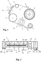
- Figure 1 shows schematically a printing machine in the form of a web-fed inkjet printing machine to which the reference number 1 is assigned as a whole.
- the material web 3 from a printing material, such as paper arrives at a printing unit 40.
- This comprises several inkjet print heads 4 arranged one behind the other along the material web 3, by means of which solvent-based and especially water-based printing inks are applied to the printing material.
- the material web 3 passes from the printing unit 40 via a deflection roller 6 to an infrared dryer system 70.
- This is equipped with several dryer modules 7, which are designed for drying or absorbing the solvent into the material web.
- the further transport path of the material web 3 goes via a tension roller 8, which is equipped with its own tension drive motor and via which the web tension is set, to a take-up roller 9.
- each of the dryer modules is equipped with several infrared radiators - in the exemplary embodiment there are eighteen.
- the dryer modules are arranged in pairs next to and behind one another in the dryer system as seen in the direction of transport.
- the pair of dryer modules 7 arranged next to one another covers the maximum format width of the printing machine 1.
- the dryer modules 7 and the individual infrared radiators can be electrically controlled separately from one another in accordance with the dimensions and color coverage of the printing material.
- the transport speed of the material web 3 is set to 5 m / s. This is a comparatively high speed which is made possible by optimizing the individual processing steps and which in particular requires a high drying rate.
- the drying process required to achieve this requirement and the dryer module 7 used for this purpose is described below with reference to FIG Figures 2 to 4 explained in more detail. Unless in these Figures have the same reference numbers as in Figure 1 are used, then identical or equivalent components and components are referred to, as they are explained in more detail above with reference to the description of the printing press.
- the directional arrows 28 indicate an air flow directed onto the surface of the printing material 3, and the directional arrows 29 an air flow leading away from the printing material 3, as well as an interaction 35 of these air flows with one another Figure 3 is explained.
- the length of the directional arrows 28; 29 symbolizes the increase in the respective flow volumes.
- the surface of the printing material 3 corresponds at the same time to the substrate plane 3a.
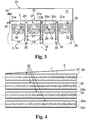
- the in Figure 3 The cross section shown comprises a section of the infrared irradiation chamber 25 along four structurally identical infrared radiator units 30.
- the cross section shows a suction chamber 31, a gas supply chamber 32 and the actual infrared treatment chamber 33.
- the gas supply space 32 is connected to a gas inlet 36 and is composed of a plurality of gas collection spaces 32a, which are fluidically connected to one another via lines 32b.
- Each emitter unit 30 has a gas collecting space 32a.
- Each gas collecting space 32a is provided with a centrally running, elongated opening 37 to the substrate treatment space 33.
- the elongated opening 37 has the shape of a longitudinal slot which extends in the substrate transport direction 5 (perpendicular to the plane of the paper) and which is provided on both longitudinal sides of gas guide elements 38a; 38b is limited.
- the infrared radiator 24 is bell-shaped and are also referred to below collectively as "air guide bell 38".
- the air guide bell 38 ends at a distance of approximately 10 mm in front of the surface of the printing material 3 (the substrate plane 3a).
- the suction space 31 has a gas outlet 34 which is connected to a fan (not shown in the figure).
- Gap-shaped suction channels 39 which run between adjacent IR radiator units 30 and which each end with the air guide elements 38a and 38b in front of the substrate plane 3a, open into the suction space 31.
- the infrared radiators 24 arranged in the substrate treatment room 33 are designed as commercially available twin tube radiators. They consist of an eight-shaped envelope made of quartz glass, which encloses two sub-spaces that are separated from one another by a central web. Their nominal power is 3,500 W. The total radiator length is 70 cm and the outer dimensions of the envelope are 34 x 14 mm.
- the opening 37 for the cooling air in the treatment room 33 and behind it the infrared radiator 24 can be seen.
- the opening width of the elongated opening 37 widens continuously in the transport direction 5.
- the width of the suction channels 39 remains constant in the transport direction 5.
- the transport direction 5 forms an angle of 10 degrees with the longitudinal sides of the suction channels 39 or with the longitudinal axes of the infrared radiators 24 (not visible in the figure).
- the method according to the invention is exemplified below with reference to FIG Figures 1 to 4 explained in more detail:
- the components of the dryer module 7 of Figure 2 have the following functions and effects.
- the front air knife 22 With the help of the guide plate 22a, the front air knife 22 generates an intensive air flow 22b directed towards the printing substrate surface 3a in the transport direction 5, which breaks through the laminar flow boundary layer on the printing substrate 3, creates turbulence and thus promotes evaporation at the beginning of the drying process.
- the front Air Knife 22 in the direction of transport Subsequent suction, some of the air and the components that have been whirled up by means of the front air knife 22 are sucked out of the dryer module 7.
- the rear Air Knife 27, with the help of the guide plate 27a also generates an intensive, Surface 3a directed air flow which breaks through the laminar flow boundary layer on the printing material 3.
- the process gas 27b that has accumulated in front of the air knife 27 is removed by the air exchanger unit 26 upstream in the transport direction.
- a plurality of air curtains 26 a running transversely to the transport direction 5 are generated by means of the air exchanger unit 26.
- a supply air flow 26b directed onto the printing substrate surface 3a is generated for each air curtain 26a and this is drawn off again immediately after it hits the printing substrate via an exhaust air flow 26c.
- the air exchanger unit 26 can take with it the moisture created as a result of the action of the infrared radiation by means of intensive air turbulence and remove it via its integrated suction system, so that undesired components cannot leave the dryer module 7 in a controlled manner.
- the treatment of the printing material 3 in the infrared radiation chamber 25 includes heating by means of infrared radiation with simultaneous exposure to dry air. So that both treatments act as effectively as possible on the printing substrate 3, the cooling air flowing from the gas supply chamber 32 through the elongated opening into the treatment chamber 33 is divided into two process gas flows 28, which are partially guided to the infrared radiator 24 and around its envelope. The infrared heater 24 is cooled and the cooling air is heated at the same time.
- Each air flow 28 directed towards the printing substrate 3 is spatially assigned an exhaust air flow 29 leading away from the printing substrate, in that the directions of the inflowing air flow 28 and the sucked in air flow 29 are directed almost in opposite directions (they enclose an angle of less than 30 degrees with one another in the exemplary embodiment) and in an interaction zone 35 meet, the interaction zone 35 lying on the surface of the printing substrate 3.
- Each of the two air flows 28 therefore meets an exhaust air flow 29 on the printing material surface.
- the resulting interaction between air flow 28 and exhaust air flow 29 leads to gas turbulence in the interaction zone 35, i.e. in the immediate vicinity of the printing substrate surface, which disrupts, reduces or even detaches the fluid dynamic laminar flow boundary layer and, as a result, an improvement in substance transport and in particular the removal of moisture from the printing material 3 can cause.
- An exhaust air flow 29 runs between two air flows 28, one of which is to be assigned to one infrared heater 24 and the other to the adjacent infrared heater 24.
- the interactions (interactions) of the flows 28, 29, 28 with one another generate a particularly intensive gas turbulence in the common strip-shaped interaction area 35 of the substrate surface, which particularly effectively disrupts, reduces or detaches the laminar flow boundary layer on the printing substrate surface, so that rapid drying is achieved.
- the shared use of an exhaust air flow 29 from two adjacent air flows 28 enables a spatially close arrangement of the infrared radiators 24 of the radiator field and thus effective drying with a compact design at the same time.
Landscapes
- Engineering & Computer Science (AREA)
- Mechanical Engineering (AREA)
- General Engineering & Computer Science (AREA)
- Life Sciences & Earth Sciences (AREA)
- Microbiology (AREA)
- Health & Medical Sciences (AREA)
- Toxicology (AREA)
- General Health & Medical Sciences (AREA)
- Chemical & Material Sciences (AREA)
- Combustion & Propulsion (AREA)
- Textile Engineering (AREA)
- Drying Of Solid Materials (AREA)
- Supply, Installation And Extraction Of Printed Sheets Or Plates (AREA)
Description
- Die Erfindung betrifft ein Verfahren zum mindestens teilweisen Trocknen eines Substrats, umfassend die Verfahrensschritte
- (a) Emittieren von Infrarotstrahlung in Richtung auf ein durch einen Prozessraum entlang eines Transportwegs und in einer Transportrichtung bewegten Substrats mittels einer Strahlereinheit, die mindestens einen Infrarotstrahler umfasst,
- (b) Erzeugen mindestens zweier auf das Substrat gerichteter Prozessgasströmungen eines Prozessgases,
- (c) mindestens teilweises Trocknen des Substrats durch Einwirkung von Infrarotstrahlung und Prozessgas auf das Substrat, und Absaugen von feuchtebeladenem Prozessgas über einen Absaugkanal aus dem Prozessraum unter Bildung einer von dem Substrat wegführenden Abluftströmung.
- Außerdem betrifft die Erfindung ein Infrarot-Trocknermodul zum Trocknen eines in einer Substratebene und in einer Transportrichtung durch einen Prozessraum bewegten Substrats, umfassend
- (a) eine Strahlereinheit, die mindestens einen eine Längsachse aufweisenden Infrarotstrahler zur Emission von Infrarotstrahlung auf die Substratebene umfasst,
- (b) eine Prozessgas-Zuführungseinheit mit einem Prozessgas-Sammelraum, der mindestens eine Einlassöffnung für die Einleitung von Prozessgas aus dem Prozessgas-Sammelraum in den Prozessraum aufweist, wobei an die Einlassöffnung ein Gasleitelement angrenzt, das sich in Richtung der Substratebene erstreckt,
- (c) eine Ablufteinheit mit mindestens einem Absaugkanal für die Ableitung von feuchtebeladenem Prozessgas aus dem Prozessraum
- Darüber hinaus geht es bei der Erfindung um ein Trocknersystem zum Trocknen eines in einer Substratebene und in einer Transportrichtung durch einen Prozessraum bewegten Substrats.
- Derartige Trocknersysteme, Trocknermodule und Trocknungsverfahren werden beispielsweise für die Trocknung von Tinten, Farben, Lacken, Klebern oder anderen lösungsmittelhaltigen Schichten, und insbesondere zur Trocknung von Papier und Pappe und Produkten hieraus sowie von Druckerzeugnissen eingesetzt.
- Zum Bedrucken bogenförmiger oder bahnförmiger Bedruckstoffe aus Papier, Pappe, Folie oder Karton mit Druckfarben sind Offset-Druckmaschinen, lithographische Druckmaschinen, Rotationsdruckmaschinen oder Flexo-Druckmaschinen gebräuchlich. Typische Inhaltsstoffe von Druckfarben und -tinten sind Öle, Harze, Wasser und Bindemittel. Bei lösungsmittelhaltigen und vor Allem wasserhaltigen Druckfarben und Lacken ist ein Trocknen erforderlich, das sowohl auf physikalischen als auch auf chemischen Trocknungsprozessen beruhen kann. Physikalische Trocknungsprozesse umfassen das Verdunsten von Lösungsmitteln (insbesondere von Wasser) und deren Diffusion in den Bedruckstoff, was auch als "Wegschlagen" bezeichnet wird. Unter chemischer Trocknung wird die Oxidation beziehungsweise Polymerisation von Druckfarben-Inhaltsstoffen verstanden. Zwischen physikalischer und chemischer Trocknung gibt es Übergänge. So kann beispielsweise das Wegschlagen der Lösungsmittel eine Annäherung monomerer Harzmoleküle bewirken, so dass diese gegebenenfalls einfacher polymerisieren. Trocknungsvorrichtungen zum Trocknen des bedruckten Bedruckstoffs dienen somit zum Entfernen von Lösungsmittel und/oder zum Auslösen von Vernetzungsreaktionen.
- Übliche IR-Trocknersysteme weisen neben Infrarotstrahlern weitere Funktionsbausteine wie Kühlung, Zuluft und Abluft auf, die in einem Luftmanagement-System in unterschiedlicher Ausprägung miteinander verknüpft und geregelt werden. So beschreibt beispielsweise die
DE 10 2010 046 756 A1 ein Trocknermodul und ein aus mehreren Trocknermodulen zusammengesetztes Trocknersystem für Druckmaschinen zum Bedrucken von Bogen- oder Rollenmaterial. - Das Trocknersystem besteht aus mehreren quer zur Transportrichtung angeordneten Trocknermodulen, von denen jedes einen auf den zu trocknenden Bedruckstoff ausgerichteten langgestreckten Infrarotstrahler aufweist, dessen Längsachse senkrecht zur Transportrichtung des Bedruckstoffs verläuft. Mittels eines regelbaren Lüftungssystems wird eine Luftströmung erzeugt, die auf den Infrarotstrahler und auf den Bedruckstoff einwirkt. Der Infrarotstrahler ist innerhalb eines Prozessraums für den Bedruckstoff angeordnet. Die Zuluft wird einem Zuluftsammelraum zugeführt und darin mittels einer Heizeinrichtung erwärmt. Außerdem wird mittels eines Ventilators die vom Infrarotstrahler erwärmte Luft abgeführt, der erwärmten Zuluft hinzugefügt und der Infrarotstrahler dadurch gekühlt.
- Aus dem Zuluftsammelraum gelangt die erwärmte Zuluft über Gasaustrittsdüsen in Form von Schlitzdüsen in den Prozessraum. Die Gasaustrittsdüsen sind beidseitig des Infrarotstrahler angeordnet, wobei die in Transportrichtung für den Bedruckstoff vordere Schlitzdüse schräg zur Bedruckstoffebene mit einer Orientierung entgegen der Transportrichtung, und die in Transportrichtung hintere Schlitzdüse ebenfalls schräg zur Bedruckstoffebene mit einer Orientierung in Transportrichtung verlaufen. Der Grad der Schrägstellung der Schlitzdüsen ist motorisch veränderbar.
- Aus dem Prozessraum wird die mit Feuchtigkeit beladene Zuluft als Abluft über einen Ansaugkanal abgeführt und teilweise einem Wärmetauscher zugeführt, und ein anderer Teil dem Zuluftsammelraum hinzugefügt.
- Die gemäß Art. 54(3) zum Stand der Technik gehörende
EP 3 363 635 A1 beschreibt ein Verfahren zum Trocknen eines Substrats mit den Verfahrensschritten: Emittieren von Infrarotstrahlung auf ein durch einen Prozessraum bewegtes Substrat mittels einer Strahlereinheit, die einen Infrarotstrahler umfasst; Erzeugen zweier auf das Substrat gerichteter Prozessgasströmungen eines Prozessgases; Trocknen des Substrats durch Einwirkung von Infrarotstrahlung und Prozessgas auf das Substrat; und Absaugen von feuchtebeladenem Prozessgas über einen Absaugkanal aus dem Prozessraum unter Bildung einer von dem Substrat wegführenden Abluftströmung. Die zwei Prozessgasströmungen werden über Ableitbleche seitlich am Infrarotstrahler vorbei geführt, bevor sie auf das Substrat einwirken. - Bei dem bekannten Trocknermodul wird das Prozessgas mittels einer eigens dafür vorgesehenen Heizeinrichtung erwärmt. Das erwärmte Prozessgas tritt über die Schlitzdüsen in Richtung auf den Bedruckstoff als erwärmte Luftströmung aus und wirkt dabei auf den zu trocknenden Bedruckstoff lokal und ansonsten mehr oder weniger undefiniert solange ein, bis sie als mit Feuchtigkeit beladene Luft an anderer Stelle wieder abgesaugt wird. Die Effektivität der Trocknungsluft hinsichtlich des Feuchteabtransports von der Substrat-Oberfläche ist daher nicht exakt reproduzierbar. Schlitzdüsen sind konstruktiv relativ aufwändig.
- Der Erfindung liegt daher die Aufgabe zugrunde, ein Trocknungsverfahren anzugeben, das reproduzierbar und effektiv ist und insbesondere hinsichtlich Homogenität und Schnelligkeit der Trocknung des Substrats zu einem verbesserten Ergebnis führt.
- Außerdem liegt der Erfindung die Aufgabe zugrunde, ein energieeffizientes IR-Trocknermodul und ein Trocknersystem bereitzustellen, die insbesondere für die Trocknung lösungsmittelhaltiger und insbesondere wasserbasierter Druckfarbe hinsichtlich Homogenität und Schnelligkeit der Trocknung verbessert sind.
- Hinsichtlich des Verfahrens wird diese Aufgabe ausgehend von einem Verfahren der eingangs genannten Gattung erfindungsgemäß dadurch gelöst, dass die mindestens zwei Prozessgasströmungen an den Infrarotstrahler geführt werden, bevor sie auf das Substrat einwirken, und dass jeder auf das Substrat gerichteten Prozessgasströmung eine vom Substrat wegführende Abluftströmung räumlich zugeordnet und benachbart ist.
- Die mindestens zwei Prozessgasströmungen werden an den Infrarotstrahler geführt, bevor sie auf das Substrat einwirken.
- Das Prozessgas ist im einfachsten Fall Luft. Es dient in erster Linie dazu, Feuchtigkeit vom Substrat abzuführen. Zu diesem Zweck wird das Prozessgas erwärmt, bevor es auf das Substrat einwirkt. Im Unterschied zum gattungsgemäßen Verfahren werden die beiden Prozessgasströmungen dadurch erwärmt, dass sie auf den heißen Infrarotstrahler und auf etwaige heiße Gasleitelemente in dessen unmittelbarer Umgebung auftreffen. Dazu werden die Prozessgasströmungen an den Infrarotstrahler geführt, so dass sie den Strahler mindestens teilweise umströmen. Gleichzeitig kühlen sie dabei den Infrarotstrahler und etwaige Gasleitelemente in der Umgebung. Durch das Aufwärmen des Prozessgases kann es eine größere Feuchtigkeitsmenge aufnehmen.
- Bei dem mindestens einen Infrarotstrahler handelt es sich beispielsweise um einen rohrförmigen Strahler mit einem langesteckten oder einem U-förmig oder ringförmig gebogenen Strahlerrohr oder um einen plattenförmigen, kachelförmigen Strahler. Er kann einen Reflektor und ein Gehäuse umfassen. Das Aufwärmen des Prozessgases durch Anströmen des Infrarotstrahlers geschieht bei diesen Infrarotstrahler-Ausführungsformen beispielsweise dadurch, dass das Prozessgas das Strahlerrohr an seinen Längsseiten umströmt, oder indem es auf die Planseiten eines plattenförmigen Infrarotstrahlers auftrifft und seitlich oder über Öffnungen in der Strahlerplatte in Richtung auf den Prozessraum weitergeleitet wird.
- Derartige Infrarotstrahler haben beispielsweise eine Emissionswellenlänge im Bereich von etwa 1000 bis 2750 nm und müssen in der Regel - insbesondere in engen Bauräumen, wie sie beispielsweise für Druckmaschinen typisch sind - aktiv gekühlt werden, um sie vor Überhitzung zu schützen. Beim erfindungsgemäßen Verfahren wird das auf den Infrarotstrahler gelangende Prozessgas erwärmt, und es kühlt dabei gleichzeitig den Infrarotstrahler. Somit dient das Kühlgas für den Infrarotstrahler nach seiner Erwärmung gleichzeitig als erwärmtes Prozessgas für den Trocknungsprozess. Auf eine zusätzliche Erwärmung des Prozessgases kann verzichtet werden, oder die zusätzliche Erwärmung des Prozessgases kann mit weniger Energieeinsatz erfolgen als dies ohne die zusätzliche Erwärmung durch den ohnehin zu kühlenden Infrarotstrahler der Fall wäre. Dadurch ergibt sich eine effiziente Energienutzung.
- Jeder auf das Substrat gerichteten Prozessgasströmung ist eine vom Substrat wegführende Abluftströmung räumlich zugeordnet.
- Das erwärmte Prozessgas wird in den Prozessraum als gerichtete und erwärmte Prozessgasströmung eingeleitet. Die Prozessgasströmung ist nicht diffus, sondern sie hat eine Hauptausbreitungsrichtung, in der sie je nach Volumen des Prozessgases und der Strömungsgeschwindigkeit auf die Substrat-Oberfläche vordringt und darauf in einem voreingestellten Winkel auftrifft und dort trocknend auf das beschichtete Substrat einwirkt. Das Einwirken bedeutet hier, dass die Prozessgasströmung die Schicht trocknet, beispielsweise indem Lösungsmittel aus der Schicht in die Gasphase aufgenommen und im Bereich der Substrat-Oberfläche Gasverwirbelungen erzeugt werden.
- Das mit Feuchtigkeit beladene Prozessgas und andere aus dem Substrat austretende gasförmige Komponenten werden als Abluft aus dem Prozessraum ganz oder teilweise abgeführt. Die gerichtete Strömung der Abluft wird durch das Absaugen über einen Absaugkanal erzeugt, so dass auch die Abluftströmung - so wie die Prozessgasströmung - eine Hauptausbreitungsrichtung hat. Die Richtung der Abluftströmung wird maßgeblich durch die Position und Ausrichtung des Absaugkanals in Bezug zur Substrat-Oberfläche bestimmt und als gedachte Verlängerung des Absaugkanals auf die Substrat-Oberfläche definiert.
- Die räumliche Zuordnung der Prozessgasströmungen und der Abluftströmung ergibt sich dadurch, dass jeder der mindestens zwei auf die Substrat-Oberfläche auftreffenden Prozessgasströmungen mindestens eine Abluftströmung benachbart ist, oder besser: wenn jede der mindestens zwei Prozessgasströmungen auf der Substrat-Oberfläche mit einer Abluftströmung zusammentrifft.
- Die räumliche Zuordnung bewirkt auf der Substrat-Oberfläche eine Interaktion der jeweiligen Gasströmungen miteinander. Die Interaktion der jeweiligen Gasströmungen wird somit einerseits dadurch bewirkt, dass sich die Strömungsrichtungen von erwärmtem Prozessgas und von feuchtebeladener Abluft unterscheiden, und andererseits dadurch, dass sie infolge der erläuterten räumlichen Zuordnung zwangsläufig aufeinandertreffen. Die dadurch erzwungene Wechselwirkung zwischen Prozessgasströmung und Abluftströmung führt zu einer Gasverwirbelung in unmittelbarer Nähe zur Substrat-Oberfläche. Diese Gasverwirbelung kann eine Störung, Verkleinerung oder sogar Ablösung der fluiddynamischen laminaren Strömungsgrenzschicht bewirken und damit einhergehend eine Verbesserung des Stofftransports und insbesondere der Abführung von Feuchtigkeit aus dem Substrat bewirken.
- Beim erfindungsgemäßen Verfahren wird aufgrund dieser Maßnahmen eine schnelle und effektive Trocknung des Substrats bei gleichzeitig möglichst geringem Energieverbrauch erreicht. Zudem ist durch Steuerung der Volumina an Prozessgas und Abluft der Grad der Gasverwirbelung beherrschbar und damit auch die Effektivität der Trocknung reproduzierbar einzustellen.
- Zur Unterstützung der Ausbildung von Gasverwirbelungen schließen die Hauptausbreitungsrichtungen von Prozessgas und Abluft im bevorzugten Fall einen Winkel von weniger als 90 Grad ein, und im besonders bevorzugten Fall sind sie gegenläufig gerichtet.
- Es hat sich als vorteilhaft erwiesen, einen eine Längsachse aufweisenden Infrarotstrahler einzusetzen, wobei der Infrarotstrahler beidseitig seiner Längsachse von je einer der beiden Prozessgasströmungen angeströmt wird.
- Der Infrarotstrahler ist dabei - vorzugsweise mittig - in einer oder unterhalb einer schlitzförmigen Einlassöffnung einer den Prozessraum begrenzenden Wandung angeordnet, so dass er mit der Wandung einen Längsspalt oder bevorzugt zwei gleich breite Längsspalte bildet, aus denen das Prozessgas entlang der beiden Längsseiten des Infrarotstrahlers in Richtung auf die Substrat-Oberfläche austritt. Die schlitzförmige Einlassöffnung ist beispielsweise als durchgehender Spalt ausgeführt oder als Aneinanderreihung einer Vielzahl von Einzelöffnungen.
- Der Infrarotstrahler trägt somit zur Erzeugung der beiden Prozessgasströmungen bei und er wird gleichzeitig von den Prozessgasströmungen angeströmt. Jede der dabei erzeugten Prozessgasströmungen wirkt in einem streifenförmigen Oberflächenbereich auf das zu trocknende Substrat ein. Gegebenenfalls sind auch die jeweils zugeordneten Absaugströmungen jeweils bevorzugt streifenförmig ausgebildet.
- Im Folgenden werden bevorzugte Verfahrensweisen des erfindungsgemäßen Verfahrens erläutert, bei denen die zum Zweck einer flächigen Infrarot-Bestrahlung des Substrats eingesetzte Strahlereinheit eine Vielzahl von Infrarotstrahlern umfasst, die jeweils parallel zueinander verlaufende Längsachsen aufweisen.
- Bei einer besonders effektiven Ausführungsform dieser Verfahrensweise wird um jede der Infrarotstrahler-Längsseiten eine auf das Substrat gerichtete Prozessgasströmung geführt, wobei benachbarte Prozessgasströmungen benachbarter Infrarotstrahler einer gemeinsamen Abluftströmung räumlich zugeordnet sind.
- Bei dieser Verfahrensvariante verläuft eine Abluftströmung jeweils zwischen zwei Prozessgasströmungen, von denen eine dem einen Infrarotstrahler und die andere dem benachbarten Infrarotstrahler zuzuordnen ist. In Richtung der Infrarotstrahler-Längsachse gesehen, ergibt sich zwischen den beiden benachbarten Infrarotstrahlern die Strömungsabfolge: Prozessgasströmung, Abluftströmung, Prozessgasströmung. Die dabei beteiligten Prozessgasströmungen interagieren (wechselwirken) mit der gemeinsamen Abluftströmung und die können vorzugsweise auch miteinander interagieren, und zwar auf einem gemeinsamen streifenförmigen Bereich der Substrat-Oberfläche.
- Durch die Wechselwirkungen (Interaktionen) der Strömungen miteinander wird in dem gemeinsamen streifenförmigen Bereich der Substrat-Oberfläche eine besonders intensive Gasverwirbelung erzeugt, die die laminare Strömungsgrenzschicht an der Substrat-Oberfläche besonders effektiv stört, verkleinert oder ablöst, so dass ein schnelles Trocknen erreicht wird. Die gemeinsame Nutzung einer Abluftströmung von zwei benachbarten Prozessgasströmungen ermöglicht eine räumlich enge Anordnung der Infrarotstrahler des Strahlerfeldes und damit ein effektives Trocknen bei gleichzeitig kompakter Bauweise.
- Die Infrarotstrahler-Längsachsen können senkrecht zur Substrat-Transportrichtung verlaufen und sich dabei beispielsweise über die gesamte Substrat-Breite erstrecken. Bei einigen Anwendungen, beispielsweise bei Druckmaschinen, ist es jedoch gewünscht, dass ein und dieselbe Vorrichtung für die Behandlung von Substraten unterschiedlicher Breite einsetzbar ist. Gegebenenfalls ist Infrarotstrahlung nur über die sogenannte "Formatbreite" erforderlich, die kleiner sein kann, als die gesamte mit Infrarotstrahlern bestückte Ausstattungsbreite der Vorrichtung. Insbesondere im Hinblick darauf hat es sich als vorteilhaft erwiesen, wenn die Infrarotstrahler-Längsachsen in Substrat-Transportrichtung verlaufen oder mit der Substrat-Transportrichtung einen Winkel von weniger als 30 Grad einschließen Dadurch, dass die Infrarotstrahler in Richtung der Substrat-Transportrichtung angeordnet sind, können randständige Infrarotstrahler der Gesamt-Bestückung nach Bedarf einfach abgeschaltet werden. Um in diesem Fall streifenförmige Inhomogenitäten in Substrat-Transportrichtung zu vermeiden, die sich infolge dieser Anordnung bei der Trocknungswirkung auf dem Substrat einstellen können, ist eine leichte Schrägstellung der Infrarotstrahler-Anordnung in Bezug auf die Transportrichtung vorteilhaft, wobei der Schrägstellungswinkel gering ist und vorteilhafterweise weniger als 30 Winkelgrade beträgt.
- Eine andere bevorzugte Verfahrensweise zeichnet sich dadurch aus, dass der Prozessraum in einem Infrarot-Trocknermodul ausgebildet ist, das in Transportrichtung des Substrats gesehen eine Kombination folgender Komponenten aufweist: ein vorderes Luftmesser (Air-Knife), einen mit mehreren parallel zueinander angeordneten Infrarotstrahlern bestückten Bestrahlungsraum, eine Lufttauschereinheit mit integrierter Absaugung und ein hinteres Luftmesser.
- Diese Komponenten sind Bestandteil eines Trocknermoduls, das wiederum Bestandteil eines Trocknersystems sein kann, in dem mehrere gleiche oder unterschiedliche Trocknermodule zusammengefasst sind. Die mittels der einzelnen Komponenten ausgeführten Verfahrensschritte werden im Folgenden erläutert. Der Bestrahlungsraum ist mit einem Strahlerfeld aus Infrarotstrahlern bestückt, und darin findet die oben erläuterte Behandlung des Substrats durch Erwärmung und Trocknung unter Einwirkung von Prozessgas, Absaugung und Infrarotstrahlung statt.
- Das vordere Luftmesser erzeugt eine intensive, auf die Substrat-Oberfläche in Transportrichtung gerichtete Luftströmung, die die laminare Strömungsgrenzschicht am Substrat durchbricht, Verwirbelungen erzeugt und dadurch die Verdunstung bereits zu Beginn des Trocknungsprozesses begünstigt.
- Beim Einbringen des Substrats in den Prozessraum können unerwünschte Substanzen in den Prozessraum eingeschleppt werden, sowohl über die Gasphase als auch mit dem Substrat, wie beispielsweise Substanzen in gasförmiger oder flüssiger Form, die an den Substrat-Oberflächen anhaften.
- Um dem entgegen zu wirken, ist bei einer bevorzugten Modifikation dieser Verfahrensweise dem vorderen Luftmesser in Transportrichtung nachfolgend eine Absaugung vorgesehen.
- Über diese optionale Absaugung wird ein Teil der Luft und der Komponenten, die mittels des vorderen Luftmessers von der Substrat-Oberfläche entfernt und in die
- Gasphase überführt worden sind, bereits von Anfang an aus dem Prozessraum entfernt.
- Beim Austritt des Substrats aus dem Prozessraum können giftige oder aus anderen Gründen unerwünschte Substanzen in gasförmiger und flüssiger Form den Prozessraum ungefiltert und unkontrolliert verlassen, darunter auch solche Substanzen, die an den Oberflächen des Substrats durch Adsorption oder Absorption haften, oder die innerhalb der Strömungsgrenzschicht immobilisiert sind. Es ist vorteilhaft, den unkontrollierten Austrag solcher Substanzen aus dem Prozessraum möglichst zu vermeiden.
- Im Hinblick darauf erzeugt das hintere Luftmesser ebenfalls eine intensive, auf die Substrat-Oberfläche gerichtete Luftströmung, die die laminare Strömungsgrenzschicht am Substrat am Prozessende durchbricht. Das dadurch vor dem Luftmesser angestaute Prozessgas wird durch die in Transportrichtung vorgelagerte Lufttauschereinheit mit integrierter Absaugung kontrolliert abgesaugt und kann über die Prozessraum-Absaugung kontrolliert entsorgt werden.
- Die Lufttauschereinheit erzeugt mindestens einen auf die Substrat-Oberfläche gerichteten Luftstrahl und sie verfügt über eine Absaugung, mittels der der Luftstrahl unmittelbar nach seiner Einwirkung auf die Substrat-Oberfläche wieder entfernt wird. Die Lufttauschereinheit besteht beispielsweise aus einer Anordnung abwechselnd angeordneter Gaseinlassdüsen und Absaugkanälen, die sich über die gesamte Substratbreite erstreckt. Sie hat die Aufgabe, die infolge der Einwirkung der Infrarotstrahlung entstandene Feuchtigkeit mittels intensiver Luftverwirbelung mitzunehmen und abzutransportieren. Die unmittelbare Absaugung trägt zu einem geringen Austrag an Verunreinigungen aus dem Trocknermodul bei.
- Das hintere Luftmesser schließt somit den Prozessschritt der Trocknung des Substrats innerhalb des betreffenden Trocknermoduls ab.
- Das vordere und das hintere Luftmesser übernehmen somit am Eingang und am Ausgang des Trocknermoduls zusätzlich die Funktion von Luftvorhängen und dichten somit das IR-Modul pneumatisch ab. Das Zusammenwirken des Bestrahlungsraums mit den beschriebenen weiteren Komponenten vermindert die Gefahr, dass Verunreinigungen, und insbesondere Wasser, in den Prozessraum eingetragen und aus dem Trocknermodul emittiert werden. Dies ermöglicht einen besonders wasserarmen Prozessraum und verbessert und optimiert den Trocknungseffekt.
- Es hat sich auch bewährt, wenn die Volumencharakteristik der Prozessgasströmung in Substrat-Transportrichtung mindestens über eine Teillänge der Infrarotstrahlerlänge zunimmt.
- Die Zunahme des Strömungsvolumens erfolgt bevorzugt kontinuierlich durch kontinuierliche Vergrößerung eines offenen Strömungsquerschnitts einer entlang der Infrarotstrahler-Längsachsen verlaufenden Austrittsöffnung für das Prozessgas in den Prozessraum. Dadurch wird es ermöglicht, dass die dynamische Einwirkung des Prozessgases und damit der Grad der Verwirbelungen am Ende des IR-Strahlerfeldes mit dem zunehmenden Grad der Verdunstung im Trocknungsprozess korreliert; das heißt, zu Beginn des Trocknungsprozesses bei noch geringer Erwärmung des Substrats und vergleichsweise geringem Verdunstungsgrad wird weniger Prozessgas zum Trocknen eingesetzt als gegen Ende des Trocknungsprozesses bei noch hoher Erwärmung des Substrats und vergleichsweise hohem Verdunstungsgrad. Dadurch wird ein besonders effizienter und sparsamer Einsatz des Prozessgases ermöglicht.
- Vorteilhafterweise umfasst das erfindungsgemäße Verfahren eine Prozessgasmengensteuerung, bei der das in das Trocknermodul eingeleitete Gasvolumen Vin kleiner eingestellt wird als das aus dem Trocknermodul abgesaugte Gasvolumen Vout.
- Das vom Prozessraum abgesaugte Gasvolumen ist größer als das in den Prozessraum eingeführte Gasvolumen. Dadurch wird gewährleistet, dass möglichst keine giftigen oder aus anderen Gründen unerwünschte Substanzen aus dem Prozessraum austreten. Das in den Prozessraum eingeführte Gasvolumen umfasst das Volumen an Prozessgas und gegebenenfalls das über die Lufttauschereinheit und das oder die Luftmesser eingebrachten Gasvolumina.
- Hinsichtlich des Infrarot-Trocknermoduls wird die eingangs genannte Aufgabe erfindungsgemäß dadurch gelöst, dass der Infrarotstrahler in Bezug auf die Einlassöffnung so angeordnet ist, dass er mit dem Gasleitelement beiderseits seiner Längsachse jeweils einen Einlasskanal für das Prozessgas bildet, und wobei jedem Prozessgas-Einlasskanal mindestens ein Prozessgas-Absaugkanal benachbart ist.
- Der Infrarotstrahler ist in Bezug auf die Einlassöffnung so angeordnet, dass er mit dem Gasleitelement beiderseits seiner Längsachse jeweils einen Einlasskanal für das Prozessgas bildet.
- Bei dem mindestens einen Infrarotstrahler handelt es sich beispielsweise um einen rohrförmigen Strahler mit einem langesteckten oder einem U-förmig gebogenen Strahlerrohr oder um einen plattenförmigen, kachelförmigen Strahler. Er hat eine Längsachse und er kann einen Reflektor und ein Gehäuse umfassen.
- Die Einlassöffnung verläuft parallel zur Infrarotstrahler-Längsachse; sie ist beispielsweise als durchgehender Spalt ausgeführt oder als Aneinanderreihung einer Vielzahl von Einzelöffnungen.
- Der mindestens eine Infrarotstrahler ist in Bezug auf die Prozessgas-Einlassöffnung so angeordnet, dass er von dem aus der Einlassöffnung in den Prozessraum einströmenden Prozessgas direkt angeströmt und umströmt wird. Dabei bildet der Zwischenraum zwischen dem Infrarotstrahler und den Gasleitelementen beiderseits seiner Längsachse jeweils einen Einlasskanal für mindestens zwei Prozessgasströmungen. Der Gasauslass des Prozessgas-Einlasskanals ist senkrecht oder in einem Winkel auf die Substratebene gerichtet.
- Die Gasleitelemente können zur Führung des aus der Einlassöffnung in die Prozesskammer ausströmenden Prozessgases in Richtung auf den Infrarotstrahler betragen; gegebenenfalls erstrecken sie sich bis nahe an den Infrarotstrahler oder auch darüber hinaus in Richtung auf die Substratebene. Durch Einstellen einer kleinen Spaltweite, also durch einen kleinen Abstand zwischen Infrarotstrahler und Gasleitelementen, ergibt sich ein Düseneffekt, der zu einer Beschleunigung der Prozessgasströmung in Richtung auf die Substratebene beitragen kann.
- Beim erfindungsgemäßen Trocknermodul werden die Gasleitelemente und der Infrarotstrahler somit vom Prozessgas gekühlt, das dadurch gleichzeitig erwärmt wird. Das Kühlgas für den Infrarotstrahler dient nach seiner Erwärmung als erwärmtes Prozessgas. Auf eine zusätzliche Erwärmung des Prozessgases kann verzichtet werden, oder die zusätzliche Erwärmung des Prozessgases kann mit weniger Energieeinsatz erfolgen als dies ohne die zusätzliche Erwärmung durch den ohnehin zu kühlenden Infrarotstrahler der Fall wäre. Dadurch ergibt sich eine effiziente Energienutzung. Außerdem ist der Infrarotstrahler Bestandteil der Prozessgas-Führung; er trägt zur Bildung und Führung der Prozessgasströmungen über mindestens eine kleine Teilstrecke bei.
- Jedem Prozessgas-Einlasskanal ist mindestens ein Prozessgas-Absaugkanal benachbart.
- Das erwärmte Prozessgas gelangt durch den Prozessgas-Einlasskanal als gerichtete und erwärmte Prozessgasströmung in den Prozessraum. Die Prozessgasströmung ist nicht diffus, sondern sie hat eine Hauptausbreitungsrichtung, in der sie je nach Volumen des Prozessgases und der Strömungsgeschwindigkeit auf die Substrat-Oberfläche vordringt und darauf in einem voreingestellten Winkel auftrifft und dort trocknend auf das Substrat einwirkt.
- Das mit Feuchtigkeit beladene Prozessgas und andere aus dem Substrat austretende gasförmige Komponenten werden aus dem Prozessraum ganz oder teilweise abgeführt. Die gerichtete Strömung der Abluft wird durch das Absaugen über einen Absaugkanal erzeugt, so dass auch die Abluftströmung - so wie die Prozessgasströmung - eine Hauptausbreitungsrichtung hat. Die Richtung der Strömung wird maßgeblich durch die Position und Ausrichtung des Absaugkanals in Bezug zur Substratebene bestimmt.
- Dadurch, dass jedem Einlasskanal ein Absaugkanal benachbart ist, ergibt es sich auch, dass jedem der mindestens zwei auf die Substrat-Oberfläche auftreffenden Prozessgasströmungen mindestens eine Abluftströmung benachbart ist, oder noch besser, dass jede der mindestens zwei Prozessgasströmungen auf der Substrat-Oberfläche mit einer Abluftströmung zusammentrifft. Dadurch wird auf der Substrat-Oberfläche eine Interaktion der jeweiligen Gasströmungen miteinander erzeugt. Die Interaktion der jeweiligen Gasströmungen wird somit einerseits dadurch bewirkt, dass sich die Strömungsrichtungen von erwärmtem Prozessgas und von feuchtebeladener Abluft unterscheiden, und andererseits dadurch, dass sie infolge der erläuterten räumlichen Zuordnung aufeinandertreffen. Die dadurch erzwungene Wechselwirkung zwischen Prozessgasströmung und Abluftströmung führt zu einer Gasverwirbelung in unmittelbarer Nähe zur Substrat-Oberfläche. Diese Gasverwirbelung kann eine Störung, Verkleinerung oder sogar Ablösung der fluiddynamischen laminaren Strömungsgrenzschicht bewirken und damit einhergehend ei-ne Verbesserung des Stofftransports und insbesondere der Abführung von Feuchtigkeit aus dem Substrat bewirken.
- Beim erfindungsgemäßen Trocknermodul wird aufgrund dieser Maßnahmen eine schnelle und effektive Trocknung des Substrats bei gleichzeitig geringem Energieverbrauch erreicht. Zudem kann durch Steuerung der Volumina von Prozessgas und Abluft der Grad der Gasverwirbelung reproduzierbar eingestellt werden und damit auch der Trocknungsgrad.
- Zur Unterstützung der Ausbildung von Gasverwirbelungen schließen die Hauptausbreitungsrichtungen von Prozessgas und Abluft im bevorzugten Fall einen Winkel von weniger als 90 Grad ein, und im besonders bevorzugten Fall sind sie gegen-läufig gerichtet. Dabei hat es sich als günstig erweisen, wenn das Gasleitelement und der Absaugkanal einen gemeinsamen Wandabschnitt haben, der in einem Abstand zur Substratebene endet.
- An einer Seite des gemeinsamen Wandabschnitts strömt das erwärmte Prozessgas in Richtung auf die Substratebene und auf der anderen Seite des gemeinsamen Wandabschnitts strömt das mit Feuchtigkeit beladene Prozessgas als Abluft von der Substratebene weg. Eine hohe Strömungsgeschwindigkeit der Prozessgasströmung und ein möglichst kleinen freien Abstand des Endes des gemeinsamen Wandabschnitts zur Substratebene tagen dazu bei, dass am Ende des gemeinsamen Wandabschnitts möglichst wenig Prozessgas direkt in den Absaugkanal gelangt. Der besagte freie Abstand zur Substratebene kann beispielsweise weniger al 10 mm betragen.
- Im Folgenden wird eine bevorzugte Ausführungsform des erfindungsgemäßen Trocknermoduls näher erläutert, bei dem die zum Zweck einer flächigen Infrarot-Bestrahlung des Substrats eingesetzte Strahlereinheit eine Vielzahl von Infrarotstrahlern umfasst, die jeweils parallel zueinander verlaufende Längsachsen aufweisen.
- Bei einer besonders effektiven Ausführungsform dieses Trocknermoduls ist zwischen benachbarten Infrarotstrahlern jeweils ein gemeinsamer Absaugkanal angeordnet.
- Infrarotstrahler und Absaugkanal wechseln sich ab. Dadurch ergibt sich ein besondere intensive Gasverwirbelung und trotzdem ein definiertes und reproduzierbares Einwirken der Prozessgasströmung auf das zu trocknende Substrat. Dabei haben Infrarotstrahler mit beiderseits benachbarten Infrarotstrahlern auf jeder ihrer Längsseiten einen Absaugkanal, der jeweils einem der beiden Prozessgasströmungen zugeordnet ist. Die Abluftströmung im Absaugkanal verläuft somit jeweils zwischen zwei Prozessgasströmungen, von denen eine dem einen Infrarotstrahler und die andere dem benachbarten Infrarotstrahler zuzuordnen ist. Die beteiligten Prozessgasströmungen interagieren (wechselwirken) mit der gemeinsamen Abluftströmung und die können vorzugsweise auch miteinander interagieren. Durch die Wechselwirkungen (Interaktionen) der Strömungen miteinander wird in einem gemeinsamen streifenförmigen Bereich der Substrat-Oberfläche eine besonders intensive Gasverwirbelung erzeugt, die die laminare Strömungsgrenzschicht an der Substrat-Oberfläche besonders effektiv stört, verkleinert oder ablöst, so dass ein schnelles Trocknen des Substrats erreicht wird. Die gemeinsame Nutzung eines Absaugkanals durch zwei benachbarte Prozessgasströmungen ermöglicht außerdem eine kompakte Bauform des Infrarotstrahlers.
- Randständige Infrarotstrahler haben nur mit dem benachbarten Infrarotstrahler einen Absaugkanal gemeinsam, wobei auf ihrer anderen Längsseite ein separater, eigener Absaugkanal angeordnet ist, oder dort eine andere Absaugung wirkt.
- Die Infrarotstrahler-Längsachsen können senkrecht zur Substrat-Transportrichtung verlaufen und sich dabei beispielsweise über die gesamte Substrat-Breite erstrecken. Bei einigen Anwendungen, beispielsweise bei Druckmaschinen, ist es jedoch gewünscht, dass ein und dieselbe Vorrichtung für die Behandlung von Substraten unterschiedlicher Breite einsetzbar ist. Gegebenenfalls ist Infrarotstrahlung nur über die sogenannte "Formatbreite" erforderlich, die kleiner sein kann, als die gesamte mit Infrarotstrahlern bestückte Ausstattungsbreite der Vorrichtung. Insbesondere im Hinblick darauf hat es sich als vorteilhaft erwiesen, wenn die Infrarotstrahler-Längsachsen in Substrat-Transportrichtung verlaufen oder mit der Substrat-Transportrichtung einen Winkel von weniger als 30 Grad einschließen Dadurch, dass die Infrarotstrahler in Richtung der Substrat-Transportrichtung angeordnet sind, können randständige Infrarotstrahler der Gesamt-Bestückung nach Bedarf einfach abgeschaltet werden. Um in diesem Fall streifenförmige Inhomogenitäten in Substrat-Transportrichtung zu vermeiden, die sich infolge dieser Anordnung bei der Trocknungswirkung auf dem Substrat einstellen können, ist eine leichte Schrägstellung der Infrarotstrahler-Anordnung in Bezug auf die Transportrichtung vorteilhaft, wobei der Schrägstellungswinkel gering ist und vorteilhafterweise weniger als 30 Winkelgrade beträgt.
- Eine andere bevorzugte Ausführungsform des Trocknermoduls zeichnet sich dadurch aus, dass der Prozessraum in einem Infrarot-Trocknermodul ausgebildet ist, das in Transportrichtung gesehen folgende Komponenten aufweist: ein vorderes Luftmesser (Air-Knife), einen mit mehreren parallel zueinander angeordneten Infrarotstrahlern bestückten Bestrahlungsraum, eine Lufttauschereinheit mit integrierter Absaugung und ein hinteres Luftmesser.
- Diese Komponenten sind Bestandteil eines Trocknermoduls, das wiederum Bestandteil eines Trocknersystems sein kann, in dem mehrere gleiche oder unterschiedliche Trocknermodule zusammengefasst sind. Die mittels der einzelnen Komponenten ausgeführten Verfahrensschritte werden im Folgenden erläutert. Der Bestrahlungsraum ist mit einem Strahlerfeld aus Infrarotstrahlern bestückt, und darin findet die oben erläuterte Behandlung des Substrats durch Erwärmung und Trocknung unter Einwirkung von Prozessgas, Absaugung und Infrarotstrahlung statt.
- Das vordere Luftmesser erzeugt eine intensive, auf die Substrat-Oberfläche in Transportrichtung gerichtete Luftströmung, die die laminare Strömungsgrenzschicht am Substrat durchbricht, Verwirbelungen erzeugt und dadurch die Verdunstung bereits zu Beginn des Trocknungsprozesses begünstigt.
- Beim Einbringen des Substrats in den Prozessraum können unerwünschte Substanzen in den Prozessraum eingeschleppt werden, sowohl über die Gasphase als auch mit dem Substrat, wie beispielsweise Substanzen in gasförmiger oder flüssiger Form, die an den Substrat-Oberflächen anhaften.
- Um dem entgegen zu wirken, ist bei einer bevorzugten Modifikation vorgesehen, dass dem vorderen Luftmesser in Transportrichtung eine Absaugung nachfolgt.
- Über diese optionale Absaugung wird ein Teil der Luft und der Komponenten, die mittels des vorderen Luftmessers von der Substrat-Oberfläche entfernt und in die Gasphase überführt worden sind, bereits von Anfang an aus dem Prozessraum entfernt.
- Beim Austritt des Substrats aus dem Prozessraum können giftige oder aus anderen Gründen unerwünschte Substanzen in gasförmiger und flüssiger Form den Prozessraum ungefiltert und unkontrolliert verlassen, darunter auch solche Substanzen, die an den Oberflächen des Substrats durch Adsorption oder Absorption haften, oder die innerhalb der Strömungsgrenzschicht immobilisiert sind. Es ist vorteilhaft, den unkontrollierten Austrag solcher Substanzen aus dem Prozessraum möglichst zu vermeiden.
- Im Hinblick darauf erzeugt das hintere Luftmesser ebenfalls eine intensive, auf die Substrat-Oberfläche gerichtete Luftströmung, die die laminare Strömungsgrenzschicht am Substrat am Prozessende durchbricht. Das dadurch vor dem Luftmesser angestaute Prozessgas wird durch die in Transportrichtung vorgelagerte Lufttauschereinheit mit integrierter Absaugung kontrolliert abgesaugt und kann über die Prozessraum-Absaugung kontrolliert entsorgt werden.
- Die Lufttauschereinheit erzeugt mindestens einen auf die Substrat-Oberfläche gerichteten Luftstrahl und sie verfügt über eine Absaugung, mittels der der Luftstrahl unmittelbar nach seiner Einwirkung auf die Substrat-Oberfläche wieder entfernt wird. Die Lufttauschereinheit besteht beispielsweise aus einer Anordnung abwechselnd angeordneter Gaseinlassdüsen und Absaugkanälen, die sich über die gesamte Substratbreite erstreckt. Sie hat die Aufgabe, die infolge der Einwirkung der Infrarotstrahlung entstandene Feuchtigkeit mittels intensiver Luftverwirbelung mitzunehmen und abzutransportieren.
- Das hintere Luftmesser schließt somit den Prozessschritt der des Substrats innerhalb des betreffenden Trocknermoduls ab.
- Das vordere und das hintere Luftmesser übernehmen somit am Eingang und am Ausgang des Trocknermoduls zusätzlich die Funktion von Luftvorhängen und dichten somit das IR-Modul pneumatisch ab. Das Zusammenwirken des Bestrahlungsraums mit den beschriebenen weiteren Komponenten vermindert die Gefahr, dass Verunreinigungen und insbesondere von Wasser in den Eintrag in den Prozess-raum eingetragen und aus dem Trocknermodul emittiert werden. Dies ermöglicht einen besonders wasserarmen Prozessraum und verbessert und optimiert den Trocknungseffekt.
- Hinsichtlich des Trocknersystem zum Trocknen eines in einer Substratebene und in einer Transportrichtung durch einen Prozessraum bewegten Substrats wird die oben genannte technische Aufgabe erfindungsgemäß dadurch gelöst, dass es mehrere Trocknermodule gemäß der Erfindung enthält, die in Transportrichtung nebeneinander und/oder hintereinander angeordnet sind.
- Nachfolgend wird die Erfindung anhand eines Ausführungsbeispiels und einer Patentzeichnung näher erläutert. In der Zeichnung zeigt in schematischer Darstellung im Einzelnen:
- Figur 1
- eine Druckmaschine mit einem Druckaggregat und einem Infrarot-Trocknersystem und einem entlang eines Transportwegs und in einer Transportrichtung transportierten Bedruckstoffs,
- Figur 2
- ein erfindungsgemäßes Trocknermodul als Teil des Trocknersystems der Druckmaschine von
Figur 1 in einem Längsschnitt in Bedruckstoff-Transportrichtung, - Figur 3
- einen Ausschnitt der Bestrahlungseinheit des erfindungsgemäßen Trocknermoduls in einem Schnitt entlang der Linie A-A von
Figur 2 , und - Figur 4
- einen Ausschnitt der Bestrahlungseinheit in einer Draufsicht auf Strahlereinheiten in Richtung des Pfeils X von
Figur 3 . - Bei Infrarotstrahlern ist ein Heizfilament aus Carbon oder Wolfram in Wendel- oder Bandform in ein inertgasgefülltes Strahlerrohr eingeschlossen, das meist aus Quarzglas gefertigt ist. Die Heizfilamente sind mit elektrischen Anschlüssen verbunden, die über ein Ende oder beiden Enden des Strahlerrohres eingeführt werden.
-
Figur 1 zeigt schematisch eine Druckmaschine in Form einer Rollen-Tintenstrahldruckmaschine, der insgesamt die Bezugsziffer 1 zugeordnet ist. Ausgehend von einem Abwickler 2 gelangt die Materialbahn 3 aus einem Bedruckstoff, wie beispielsweise aus Papier, zu einem Druckaggregat 40. Dieses umfasst mehrere, entlang der Materialbahn 3 hintereinander angeordnete Tintenstrahldruckköpfe 4, durch die auf den Bedruckstoff lösungsmittelhaltige und insbesondere wasserhaltige Druckfarben aufgetragen werden. - In Transportrichtung 5 gesehen, gelangt die Materialbahn 3 vom Druckaggregat 40 über eine Umlenkwalze 6 anschließend zu einem Infrarot-Trocknersystem 70. Dieses ist mit mehreren Trocknermodulen 7 bestückt, die für das Trocknen beziehungsweise Wegschlagen des Lösungsmittels in die Materialbahn ausgelegt sind.
- Der weitere Transportweg der Materialbahn 3 geht über eine Zugwalze 8, die mit eigenem Zugantriebsmotor ausgestattet ist und über die die Einstellung der Bahnspannung erfolgt, zu einer Aufwickelrolle 9.
- In dem Trocknersystem 70 sind mehrere - im Ausführungsbeispiel sind es vier-Trocknermodule 7 zusammengefasst. Jedes der Trocknermodule ist mit mehreren Infrarotstrahlern - im Ausführungsbeispiel sind es achtzehn - ausgestattet.
- Die Trocknermodule sind im Trocknersystem in Transportrichtung gesehen paarweise neben- und hintereinander angeordnet. Das jeweils nebeneinander angeordnete Paar der Trocknermodule 7 deckt die maximale Formatbreite der Druckmaschine 1 ab. Entsprechend der Abmessungen und Farbbelegung des Bedruckstoffs sind die Trocknermodule 7 und die einzelnen Infrarotstrahler getrennt voneinander elektrisch ansteuerbar.
- Die Transportgeschwindigkeit der Materialbahn 3 wird auf 5 m/s eingestellt. Dabei handelt es sich um eine vergleichsweise hohe Geschwindigkeit, die durch eine Optimierung der einzelnen Bearbeitungsschritte ermöglicht wird, und die insbesondere eine hohe Trocknungsrate erfordert. Das zum Erreichen dieser Anforderung erforderliche Trocknungsverfahren und das dafür eingesetzte Trocknermodul 7 wird im Folgenden anhand der
Figuren 2 bis 4 näher erläutert. Sofern in diesen Figuren dieselben Bezugsziffern wie inFigur 1 verwendet sind, so sind damit baugleiche oder äquivalente Bauteile und Bestandteile bezeichnet, wie sie oben anhand der Beschreibung der Druckmaschine näher erläutert sind. - Bei der in
Figur 2 schematisch gezeigten Ausführungsform eines erfindungsgemäßen Trocknermoduls 7 umschließt ein Gehäuse 21 einen Behandlungsraum (=Prozessraum) für den Bedruckstoff 3 mit folgenden Komponenten (in Transportrichtung 5 gesehen): ein vorderes Air-Knife 22 mit Luftleitblech 22a, eine dem vorderen Air Knife 22 unmittelbar nachgeordnete Absaugung 23, eine mit den achtzehn Infrarotstrahlern 24 bestückte Infrarot-Bestrahlungskammer 25, deren Längsachsen 24a etwa in Transportrichtung 5 verlaufen und die parallel zueinander angeordnet sind, eine Lufttauschereinheit 26 mit abwechselnd angeordneten Gaseinlassdüsen und Absaugkanälen (26b, 26a) und ein hinteres Air Knife 22 mit einem abschließenden Luftleitblech 22a. - Die Richtungspfeile 28 deuten eine auf die Oberfläche des Bedruckstoffs 3 gerichtete Luftströmung, und die Richtungspfeile 29 eine vom Bedruckstoff 3 wegführende Luftströmung, sowie eine Wechselwirkung 35 dieser Luftströmungen miteinander an, die anhand
Figur 3 erläutert wird. Die in Transportrichtung 5 zunehmende Länge der Richtungspfeile 28; 29 symbolisiert die Zunahme der jeweiligen Strömungsvolumina. Die Oberfläche des Bedruckstoffs 3 entspricht gleichzeitig der Substratebene 3a. - Der in
Figur 3 gezeigte Querschnitt umfasst einen Ausschnitt der Infrarot-Bestrahlungskammer 25 entlang von vier baugleichen Infrarotstrahlereinheiten 30. Der Querschnitt zeigt einen eine Absaugraum 31, einen Gaszuführungsraum 32 und den eigentlichen Infrarot-Behandlungsraum 33. - Der Gaszuführungsraum 32 ist mit einem Gaseinlass 36 verbunden und setzt sich aus mehreren Gassammelräumen 32a zusammen, die über Leitungen 32b fluidisch miteinander verbunden sind. Jede Strahlereinheit 30 verfügt über einen Gassammelraum 32a. Jeder Gassammelraum 32a ist mit einer mittig verlaufenden, länglichen Öffnung 37 zum Substrat-Behandlungsraum 33 versehen. Die länglichen Öffnung 37 hat die Form eines sich in Substrat-Transportrichtung 5 (senkrecht zur Papierebene) erstreckenden Längsschlitzes, der an beiden Längsseiten von Gasleitelementen 38a; 38b begrenzt ist. In dem in
Figur 3 gezeigten Querschnitt überwölben die Gasleitelemente 38a; 38b den Infrarotstrahler 24 glockenartig und werden im Folgenden zusammen auch als "Luftleitglocke 38" bezeichnet. Die Luftleitglocke 38 endet in einem Abstand von etwa 10 mm vor der Oberfläche des Bedruckstoffs 3 (der Substratebene 3a). - Der Absaugraum 31 hat einen Gasauslass 34, der mit einem (in der Figur nicht gezeigten) Ventilator verbunden ist. In den Absaugraum 31 münden spaltförmige Absaugkanäle 39, die zwischen benachbarten IR-Strahlereinheiten 30 verlaufen und die jeweils mit den Luftleitelementen 38a beziehungsweise 38b vor der Substratebene 3a enden.
- Die im Substrat-Behandlungsraum 33 angeordneten Infrarotstrahler 24 sind als handelsübliche Zwillingsrohrstrahler ausgebildet. Sie bestehen aus einem im Querschnitt achtförmigen Hüllkolben aus Quarzglas, der zwei Teilräume umschließt, die durch einen Mittelsteg voneinander getrennt sind. Ihre Nominal-Leistung beträgt 3.500 W. Die Gesamtstrahlerlänge beträgt 70 cm und die Außenabmessungen des Hüllkolbens betragen 34 x 14 mm.
- Aus der Draufsicht auf die Strahlereinheiten 30 von
Figur 4 sind die Öffnung 37 für die Kühlluft in den Behandlungsraum 33 und dahinter die Infrarotstrahler 24 erkennbar. Die Öffnungsweite der länglichen Öffnung 37 erweitert sich in Transportrichtung 5 kontinuierlich. Die Weite der Absaugkanäle 39 bleibt hingegen in Transportrichtung 5 konstant. Die Transportrichtung 5 schließt mit den Längsseiten der Absaugkanäle 39, beziehungsweise mit den Längsachsen der (in der Figur nicht sichtbaren) Infrarotstrahler 24 einen Winkel von 10 Grad ein. - Nachfolgend wird das erfindungsgemäße Verfahren beispielhaft anhand der
Figuren 1 bis 4 näher erläutert:
Die Komponenten des Trocknermoduls 7 vonFigur 2 haben folgende Funktionen und Wirkungen. - Das vordere Air Knife 22 erzeugt unter Mithilfe des Leitblechs 22a eine intensive, auf die Bedruckstoff-Oberfläche 3a in Transportrichtung 5 gerichtete Luftströmung 22b, die die laminare Strömungsgrenzschicht am Bedruckstoff 3 durchbricht, Verwirbelungen erzeugt und dadurch die Verdunstung bereits zu Beginn des Trocknungsprozesses begünstigt. Über die dem vorderen Air Knife 22 in Transportrichtung nachgeordnete Absaugung wird ein Teil der Luft und der Komponenten, die mittels des vorderen Air Knifes 22 aufgewirbelt worden sind, aus dem Trocknermoduls 7 abgesaugt.
- Damit beim Austritt des Bedruckstoffs 3 aus dem Trocknermodul 7 möglichst keine giftigen oder aus anderen Gründen unerwünschten Substanzen in gasförmiger und flüssiger Form den Prozessraum ungefiltert und unkontrolliert verlassen, erzeugt das hintere Air Knife 27 unter Mithilfe des Leitblechs 27a ebenfalls eine intensive, auf die Bedruckstoff-Oberfläche 3a gerichtete Luftströmung, die die laminare Strömungsgrenzschicht am Bedruckstoff 3 durchbricht. Das dadurch vor dem Air Knife 27 angestaute Prozessgas 27b wird durch die in Transportrichtung vorgelagerte Lufttauschereinheit 26 entfernt. Zu diesem Zweck werden mittels der Lufttauschereinheit 26 mehrere quer zur Transportrichtung 5 verlaufende Luftvorhänge 26a erzeugt. Mittels sich abwechselnder Gaseinlassdüsen und Absaugkanäle wird bei jedem Luftvorhang 26a ein auf die Bedruckstoff-Oberfläche 3a gerichteter Zuluftstrom 26b erzeugt und dieser unmittelbar nach dem Auftreffen auf den Bedruckstoff über einen Abluftstrom 26c wieder abgezogen. Die Lufttauschereinheit 26 kann die infolge der Einwirkung der Infrarotstrahlung entstandene Feuchtigkeit mittels intensiver Luftverwirbelung mitnehmen und über ihre integrierte Absaugung entfernen, so dass unerwünschte Komponenten das Trocknermodul 7 nicht kontrolliert verlassen können.
- Die Behandlung des Bedruckstoffs 3 in der Infrarot-Bestrahlungskammer 25 umfasst ein Erhitzen mittels Infrarotstrahlung bei gleichzeitiger Beaufschlagung mit trockener Luft. Damit beide Behandlungen möglichst effektiv auf den Bedruckstoff 3 einwirken, wird die aus dem Gaszuführungsraum 32 durch die längliche Öffnung in den Behandlungsraum 33 einströmende Kühlluft in zwei Prozessgasströmungen 28 geteilt, die zum Infrarotstrahler 24 und um dessen Hüllkolben teilweise herum geführt werden. Dabei wird der Infrarotstrahler 24 gekühlt und gleichzeitig wird die Kühlluft erwärmt.
- Zwischen der Wandung des Infrarotstrahlers 24 und der Luftleitglocke 38 ergibt sich ein enger Spalt, der die beiden Luftströmungen 28 in Richtung auf den Bedruckstoff 3 beschleunigt, so dass sie auf diesen intensiv einwirken und Feuchtigkeit in die Gasphase überführen oder aufnehmen. Infolge ihrer Erwärmung ist die Aufnahmefähigkeit der Kühlluft für Feuchtigkeit erhöht.
- Jeder auf den Bedruckstoff 3 gerichteten Luftströmung 28 ist eine vom Bedruckstoff wegführende Abluftströmung 29 räumlich zugeordnet, indem die Richtungen von einströmendem Luftstrom 28 und angesaugtem Luftstrom 29 nahezu gegenläufig gerichtet sind (sie schließen im Ausführungsbeispiel einen Winkel von weniger als 30 Grad miteinander ein) und in einer Wechselwirkungszone 35 aufeinandertreffen, wobei die Wechselwirkungszone 35 an der Oberfläche des Bedruckstoffs 3 liegt. Jede der beiden Luftströmungen 28 trifft daher auf der Bedruckstoff-Oberfläche mit einer Abluftströmung 29 zusammen. Die dadurch erzwungene Wechselwirkung zwischen Luftströmung 28 und Abluftströmung 29 führt zu einer Gasverwirbelung in der Wechselwirkungszone 35, also in unmittelbarer Nähe zur Bedruckstoff-Oberfläche, die eine Störung, Verkleinerung oder sogar Ablösung der fluiddynamischen laminaren Strömungsgrenzschicht bewirken und damit einhergehend eine Verbesserung des Stofftransports und insbesondere der Abführung von Feuchtigkeit aus dem Bedruckstoff 3 bewirken kann.
- Eine Abluftströmung 29 verläuft jeweils zwischen zwei Luftströmungen 28, von denen eine dem einen Infrarotstrahler 24 und die e andere dem benachbarten Infrarotstrahler 24 zuzuordnen ist. Wie
Figur 3 zeigt, ergibt sich zwischen benachbarten Infrarotstrahlern 24 die Strömungsabfolge: Luftströmung 28 - Abluftströmung 29 - Luftströmung 28. Diese Luftströmungen 28 interagieren (wechselwirken) mit der gemeinsamen Abluftströmung 29 und die können vorzugsweise auch miteinander interagieren, und zwar auf einem gemeinsamen streifenförmigen Bereich 36 an der Bedruckstoff-Oberfläche. Die Wechselwirkungen (Interaktionen) der Strömungen 28, 29, 28 miteinander erzeugen in dem gemeinsamen streifenförmigen Wechselwirkungsbereich 35 der Substrat-Oberfläche eine besonders intensive Gasverwirbelung die die laminare Strömungsgrenzschicht an der Bedruckstoff-Oberfläche besonders effektiv stört, verkleinert oder ablöst, so dass ein schnelles Trocknen erreicht wird. Die gemeinsame Nutzung einer Abluftströmung 29 von zwei benachbarten Luftströmungen 28 ermöglicht eine räumlich enge Anordnung der Infrarotstrahler 24 des Strahlerfeldes und damit ein effektives Trocknen bei gleichzeitig kompakter Bauweise.
Claims (15)
- Verfahren zum mindestens teilweisen Trocknen eines Substrats, (3) umfassend die Verfahrensschritte:(a) Emittieren von Infrarotstrahlung in Richtung auf ein durch einen Prozessraum entlang eines Transportwegs und in einer Transportrichtung bewegten Substrats mittels einer Strahlereinheit, die mindestens einen Infrarotstrahler (24) umfasst,(b) Erzeugen mindestens zweier auf das Substrat gerichteter Prozessgasströmungen eines Prozessgases,(c) mindestens teilweises Trocknen des Substrats durch Einwirkung von Infrarotstrahlung und Prozessgas auf das Substrat, und Absaugen von feuchtebeladenem Prozessgas über einen Absaugkanal aus dem Prozessraum unter Bildung einer von dem Substrat wegführenden Abluftströmung, dadurch gekennzeichnet, dass die mindestens zwei Prozessgasströmungen (28) an den Infrarotstrahler (24) geführt werden, bevor sie auf das Substrat einwirken, und dass jeder auf das Substrat gerichteten Prozessgasströmung eine vom Substrat wegführende Abluftströmung räumlich zugeordnet und benachbart ist.
- Verfahren nach Anspruch 1, dadurch gekennzeichnet, dass ein eine Längsachse aufweisender Infrarotstrahler eingesetzt wird, und dass der Infrarotstrahler beidseitig seiner Längsachse von je einer der beiden Prozessgasströmungen angeströmt wird.
- Verfahren nach Anspruch 1 oder 2, dadurch gekennzeichnet, dass die mindestens zwei Prozessgasströmungen streifenförmig auf das zu trocknende Substrat einwirken, und dass den streifenförmigen Prozessgasströmungen bevorzugt jeweils eine streifenförmige Abluftströmung räumlich zugeordnet ist.
- Verfahren nach einem der vorhergehenden Ansprüche, dadurch gekennzeichnet, dass zum Zweck einer flächigen Infrarot-Bestrahlung des Substrats eine Strahlereinheit eingesetzt wird, die eine Vielzahl von Infrarotstrahlern umfasst, die jeweils parallel zueinander verlaufende Längsachsen aufweisen, wobei bevorzugt um jede der Infrarotstrahler-Längsachsen eine auf das Substrat gerichtete Prozessgasströmung geführt wird, wobei benachbarte Prozessgasströmungen benachbarter Infrarotstrahler einer gemeinsamen Abluftströmung räumlich zugeordnet sind.
- Verfahren nach Anspruch 4, dadurch gekennzeichnet, dass die Infrarotstrahler-Längsachsen in Substrat-Transportrichtung verlaufen oder mit der Substrat-Transportrichtung einen Winkel von weniger als 30 Grad einschließen.
- Verfahren nach einem der Ansprüche 4 oder 5, dadurch gekennzeichnet, dass der Prozessraum in einem Infrarot-Trocknermodul ausgebildet ist, das in Transportrichtung des Substrats gesehen eine Kombination folgender Komponenten aufweist: ein vorderes Luftmesser (Air-Knife), einen mit mehreren parallel zueinander angeordneten Infrarotstrahlern bestückten Bestrahlungsraum, eine Lufttauschereinheit mit integrierter Absaugung und ein hinteres Luftmesser, wobei bevorzugt dem vorderen Luftmesser in Transportrichtung eine Absaugung nachfolgt.
- Verfahren nach einem der Ansprüche 4 bis 6, dadurch gekennzeichnet, dass der Prozessgasströmung eine Volumencharakteristik aufgeprägt wird, die in Substrat-Transportrichtung mindestens über eine Teillänge der Infrarotstrahlerlänge zunimmt.
- Verfahren nach einem der vorhergehenden Ansprüche, dadurch gekennzeichnet, dass mittels einer Prozessgasmengensteuerung das in das Trocknermodul eingeleitete Gasvolumen Vin kleiner eingestellt wird als das aus dem Trocknermodul abgesaugte Gasvolumen Vout.
- Infrarot-Trocknermodul zum Trocknen eines in einer Substratebene und in einer Transportrichtung durch einen Prozessraum bewegten Substrats, umfassend(a) eine Strahlereinheit, die mindestens einen eine Längsachse aufweisenden Infrarotstrahler (24) zur Emission von Infrarotstrahlung auf die Substratebene umfasst,(b) eine Prozessgas-Zuführungseinheit mit einem Prozessgas-Sammelraum, der mindestens eine Einlassöffnung für die Einleitung von Prozessgas (27b) aus dem Prozessgas-Sammelraum in den Prozessraum aufweist, wobei an die Einlassöffnung ein Gasleitelement angrenzt, das sich in Richtung der Substratebene erstreckt,(c) eine Ablufteinheit mit mindestens einem Absaugkanal für die Ableitung von feuchtebeladenem Prozessgas aus dem Prozessraum, dadurch gekennzeichnet, dass der Infrarotstrahler in Bezug auf die Einlassöffnung so angeordnet ist, dass er mit dem Gasleitelement beiderseits seiner Längsachse jeweils einen Einlasskanal für das Prozessgas bildet, und wobei jedem Prozessgas-Einlasskanal mindestens ein Prozessgas-Absaugkanal benachbart ist.
- Trocknermodul nach Anspruch 9, dadurch gekennzeichnet, dass das Gasleitelement und der Absaugkanal einen gemeinsamen Wandabschnitt haben, der in einem Abstand zur Substratebene endet.
- Trocknermodul nach Anspruch 9 oder 10, dadurch gekennzeichnet, dass die Strahlereinheit eine Vielzahl von Infrarotstrahlern umfasst, die jeweils parallel zueinander verlaufende Längsachsen aufweisen, wobei bevorzugt zwischen benachbarten Infrarotstrahlern ein gemeinsamer Absaugkanal angeordnet ist.
- Trocknermodul nach Anspruch 11, dadurch gekennzeichnet, dass die Infrarotstrahler-Längsachsen in Substrat-Transportrichtung verlaufen oder mit der Substrat-Transportrichtung einen Winkel von weniger als 30 Grad einschließen.
- Trocknermodul nach einem der Ansprüche11 oder 12, dadurch gekennzeichnet, dass der Prozessraum in Transportrichtung gesehen folgende Komponenten aufweist: ein vorderes Luftmesser (Air-Knife), einen mit mehreren parallel zueinander angeordneten Infrarotstrahlern bestückten Bestrahlungsraum, eine Lufttauschereinheit mit integrierter Absaugung und ein hinteres Luftmesser, wobei bevorzugt dem vorderen Luftmesser in Transportrichtung eine Absaugung nachfolgt.
- Trocknermodul nach einem der Ansprüche 11 bis 13, dadurch gekennzeichnet, dass der Prozessgasströmung eine Volumencharakteristik aufgeprägt wird, die in Substrat-Transportrichtung mindestens über eine Teillänge der Infrarotstrahlerlänge zunimmt.
- Trocknersystem zum Trocknen eines in einer Substratebene und in einer Transportrichtung durch einen Prozessraum bewegten Substrats, das mehrere Trocknermodule nach einem der Ansprüche 11 bis 14 enthält, die in Transportrichtung nebeneinander und/oder hintereinander angeordnet sind.
Applications Claiming Priority (2)
| Application Number | Priority Date | Filing Date | Title |
|---|---|---|---|
| DE102017129017.6A DE102017129017A1 (de) | 2017-12-06 | 2017-12-06 | Verfahren zum Trocknen eines Substrats, Trocknermodul zur Durchführung des Verfahrens sowie Trocknersystem |
| PCT/EP2018/083303 WO2019110484A1 (de) | 2017-12-06 | 2018-12-03 | Verfahren zum trocknen eines substrats, trocknermodul zur durchführung des verfahrens sowie trocknersystem |
Publications (2)
| Publication Number | Publication Date |
|---|---|
| EP3720716A1 EP3720716A1 (de) | 2020-10-14 |
| EP3720716B1 true EP3720716B1 (de) | 2021-09-22 |
Family
ID=64650377
Family Applications (1)
| Application Number | Title | Priority Date | Filing Date |
|---|---|---|---|
| EP18815146.8A Active EP3720716B1 (de) | 2017-12-06 | 2018-12-03 | Verfahren zum trocknen eines substrats, trocknermodul zur durchführung des verfahrens sowie trocknersystem |
Country Status (6)
| Country | Link |
|---|---|
| US (2) | US12025375B2 (de) |
| EP (1) | EP3720716B1 (de) |
| JP (1) | JP7114712B2 (de) |
| CN (1) | CN111465501B (de) |
| DE (1) | DE102017129017A1 (de) |
| WO (1) | WO2019110484A1 (de) |
Families Citing this family (8)
| Publication number | Priority date | Publication date | Assignee | Title |
|---|---|---|---|---|
| DE102017129017A1 (de) | 2017-12-06 | 2019-06-06 | Heraeus Noblelight Gmbh | Verfahren zum Trocknen eines Substrats, Trocknermodul zur Durchführung des Verfahrens sowie Trocknersystem |
| DE102019126701A1 (de) * | 2019-10-02 | 2021-04-08 | Heraeus Noblelight Gmbh | Infrarot-Trocknermodul und Trocknersystem |
| DE202020002017U1 (de) * | 2020-05-08 | 2020-05-25 | Gunther Ackermann | Vorrichtung zur Bestrahlung eines Substrates |
| CN115483357B (zh) * | 2021-06-15 | 2025-07-08 | 深圳市易天自动化设备股份有限公司 | 一种oled及其基板清洗后风干机及其风干工艺 |
| DE102022124575A1 (de) * | 2022-09-23 | 2024-03-28 | Duo Technik Gmbh | Vorrichtung zum Trocknen von Flächengebilden |
| DE102023200207A1 (de) * | 2023-01-12 | 2024-07-18 | Bhs Corrugated Maschinen- Und Anlagenbau Gmbh | Vorrichtung zum Trocknen einer bedruckten Materialbahn |
| DE202023103004U1 (de) * | 2023-05-31 | 2023-07-18 | Gunther Ackermann | Umluft-Prozess-System |
| DE102024203235A1 (de) * | 2024-04-09 | 2025-10-09 | Bhs Corrugated Maschinen- Und Anlagenbau Gmbh | Anlage, mit einer Trockenstrecke, Trockenstrecke und Verfahren zum Betrieb einer Anlage mit Trockenstrecke |
Family Cites Families (68)
| Publication number | Priority date | Publication date | Assignee | Title |
|---|---|---|---|---|
| US3460265A (en) * | 1967-02-14 | 1969-08-12 | Horace L Smith Jr | Methods of drying |
| US3403456A (en) * | 1967-02-14 | 1968-10-01 | White Consolidated Ind Inc | Impingement type drying apparatus |
| US3525164A (en) * | 1968-12-10 | 1970-08-25 | Wolverine Corp | Apparatus for gaseous treatment of moving webs |
| IT965804B (it) * | 1972-05-10 | 1974-02-11 | Minnesota Mining & Mfg | Procedimento e dispositivo per la asciugatura rapida di pellicole fotografiche |
| US3973328A (en) * | 1972-05-26 | 1976-08-10 | Ilford Limited | Paper material dryer |
| US3900959A (en) * | 1973-05-07 | 1975-08-26 | Minnesota Mining & Mfg | Combined infra-red and air flow drying for photographic film |
| US5024596A (en) * | 1976-04-07 | 1991-06-18 | Smith Thomas M | Infra-red equipment |
| US4378207A (en) * | 1979-11-16 | 1983-03-29 | Smith Thomas M | Infra-red treatment |
| US4443185A (en) * | 1979-03-13 | 1984-04-17 | Smith Thomas M | Heating of webs |
| US4146974A (en) * | 1977-09-19 | 1979-04-03 | Pray Robert W | Drying apparatus |
| US4336279A (en) * | 1978-07-04 | 1982-06-22 | Metzger Wesley A | Apparatus and process for drying and curing coated substrates |
| US4494316A (en) * | 1983-03-14 | 1985-01-22 | Impact Systems, Inc. | Apparatus for drying a moving web |
| FI75008C (fi) * | 1986-03-14 | 1992-02-17 | Valmet Oy | Svaevtork och foerfarande foer effektivering av dess funktion. |
| US4779355A (en) * | 1986-12-04 | 1988-10-25 | Dec-E-Tech, Inc. | Efficient dryer and drying process |
| FI77707C (fi) * | 1987-06-04 | 1989-04-10 | Valmet Paper Machinery Inc | Foerfarande foer kontaktloes torkning av en pappers- eller kartongbana. |
| US4787547A (en) * | 1987-06-11 | 1988-11-29 | Advance Systems, Inc. | Mounting means for air bars |
| US4785986A (en) * | 1987-06-11 | 1988-11-22 | Advance Systems, Inc. | Paper web handling apparatus having improved air bar with dimensional optimization |
| US4756091A (en) * | 1987-06-25 | 1988-07-12 | Herbert Van Denend | Hybrid high-velocity heated air/infra-red drying oven |
| US5009016A (en) * | 1987-11-26 | 1991-04-23 | Valmet Oy | Method for on-machine coating-drying of a paper web or the like |
| ES2030935T3 (es) * | 1988-05-13 | 1992-11-16 | Hoechst Aktiengesellschaft | Procedimiento y dispositivo para el secado de una capa de liquido aplicada sobre un material de soporte en movimiento. |
| US5092059A (en) * | 1988-06-07 | 1992-03-03 | W. R. Grace & Co.-Conn. | Infrared air float bar |
| US5035066A (en) * | 1988-06-07 | 1991-07-30 | W. R. Grace & Co.-Conn. | Ultraviolet air floatation bar |
| NO890790L (no) * | 1989-02-24 | 1990-08-27 | Severin Severinsen | Fremgangsmaate ved fiksering av en bane, og fikseringsanlegg for fiksering av baner. |
| US5010659A (en) * | 1989-09-08 | 1991-04-30 | W. R. Grace & Co.-Conn. | Infrared drying system |
| US5099586A (en) * | 1989-09-08 | 1992-03-31 | W. R. Grace & Co.-Conn. | Reflector assembly for heating a substrate |
| GB8922058D0 (en) * | 1989-09-29 | 1989-11-15 | T R H Jackson Ltd | Electric heater |
| DE4110875A1 (de) * | 1991-04-04 | 1992-10-08 | Voith Gmbh J M | Trockenpartie |
| SE468287B (sv) * | 1991-04-22 | 1992-12-07 | Infraroedteknik Ab | Saett resp anordning foer behandling av en kontinuerlig materialbana |
| GB9116120D0 (en) * | 1991-07-25 | 1991-09-11 | G E W Ec Ltd | U.v.dryers |
| CA2078290A1 (en) * | 1991-10-24 | 1993-04-25 | W.R. Grace & Co.-Conn. | Combination infrared and air flotation dryer |
| US5317127A (en) * | 1992-08-28 | 1994-05-31 | Pitney Bowes Inc. | Apparatus including air blowing and infrared light means for drying ink on a sheet |
| GB9323954D0 (en) * | 1993-11-19 | 1994-01-05 | Spooner Ind Ltd | Improvements relating to web drying |
| GB2284469B (en) * | 1993-12-01 | 1997-12-03 | Spectral Technology Limited | Lamp assembly |
| US5634402A (en) * | 1995-10-12 | 1997-06-03 | Research, Incorporated | Coating heater system |
| US5606805A (en) * | 1996-04-01 | 1997-03-04 | Meyer; Jens-Uwe | Process for drying a coated moving web |
| US5713138A (en) * | 1996-08-23 | 1998-02-03 | Research, Incorporated | Coating dryer system |
| US5867920A (en) * | 1997-02-05 | 1999-02-09 | Megtec Systems, Inc. | High speed infrared/convection dryer |
| JP3070511B2 (ja) * | 1997-03-31 | 2000-07-31 | 日本電気株式会社 | 基板乾燥装置 |
| FR2771161B1 (fr) * | 1997-11-14 | 2000-01-14 | Solaronics | Systeme convecto-radiatif pour traitement thermique d'une bande continue |
| US6118130A (en) * | 1998-11-18 | 2000-09-12 | Fusion Uv Systems, Inc. | Extendable focal length lamp |
| JP2002052850A (ja) * | 2000-08-14 | 2002-02-19 | Toppan Printing Co Ltd | 環境配慮型高光沢印刷物の製造方法 |
| JP4656358B2 (ja) * | 2001-02-15 | 2011-03-23 | 上垣 健男 | 乾燥装置 |
| US6634120B2 (en) * | 2001-03-26 | 2003-10-21 | Voith Paper Patent Gmbh | Apparatus for coating moving fiber webs |
| US6536134B1 (en) * | 2001-08-28 | 2003-03-25 | Graphic Specialists, Inc. | Drier for commercial printers |
| JP2003094605A (ja) * | 2001-09-26 | 2003-04-03 | Toppan Printing Co Ltd | 乾燥器 |
| US6550905B1 (en) * | 2001-11-19 | 2003-04-22 | Dotrix N.V. | Radiation curable inkjet ink relatively free of photoinitiator and method and apparatus of curing the ink |
| US6655040B2 (en) * | 2002-01-04 | 2003-12-02 | The Diagnostics Group, Inc. | Combination ultraviolet curing and infrared drying system |
| CH695677A5 (fr) | 2002-10-01 | 2006-07-31 | Bobst Sa | Dispositif pour le séchage d'une matière imprimée. |
| EP2610568A1 (de) * | 2003-03-26 | 2013-07-03 | Fujifilm Corporation | Trockenverfahren für eine Beschichtung |
| DE102005054995B4 (de) * | 2005-07-28 | 2014-03-13 | Otto Junker Gmbh | Düsensystem für die Behandlung von bahnförmigem Gut |
| BRPI0707331A2 (pt) | 2006-01-25 | 2011-05-03 | Bekaert Sa Nv | sistema de convecção para instalação de secadora |
| CN101375123B (zh) | 2006-01-25 | 2011-06-08 | 贝卡尔特股份有限公司 | 火焰干燥器 |
| JP2007320183A (ja) * | 2006-06-01 | 2007-12-13 | Daikin Ind Ltd | 印刷機の排気システム |
| JP2009236355A (ja) * | 2008-03-26 | 2009-10-15 | Fujifilm Corp | 乾燥方法及び装置 |
| JP2009243701A (ja) * | 2008-03-28 | 2009-10-22 | Fujifilm Corp | 乾燥装置及び画像形成装置 |
| ES2523835T3 (es) * | 2009-06-05 | 2014-12-01 | Megtec Systems, Inc. | Conjunto de canal adaptado para ser insertado en una barra de aire y un método para configurar el flujo de aire en el conjunto de canal |
| JP4967013B2 (ja) | 2009-12-11 | 2012-07-04 | 東京エレクトロン株式会社 | 基板処理装置、基板処理方法及びこの基板処理方法を実行させるためのプログラムを記録した記録媒体 |
| DE102010046756A1 (de) | 2010-09-28 | 2012-03-29 | Eltosch Torsten Schmidt Gmbh | Trocknermodul für Druckmaschinen |
| JP5421934B2 (ja) * | 2011-01-13 | 2014-02-19 | 東京エレクトロン株式会社 | 電極製造装置、電極製造方法 |
| CN102632700A (zh) * | 2012-04-18 | 2012-08-15 | 广东新优威印刷装备科技有限公司 | 印刷机 |
| FI124272B (fi) | 2012-06-06 | 2014-05-30 | Ccm Power Oy | Kuivuri ja menetelmä materiaalin kuivaamiseksi |
| EP3003578A4 (de) * | 2013-05-31 | 2018-02-21 | Rosenberg, Joe, I.v. | Verfahren und vorrichtung zur umwandlung einer kalten netzdruckpresse für eine hybride warme und kalte druckpresse |
| WO2017194335A2 (en) * | 2016-05-09 | 2017-11-16 | Intrinsic Id B.V. | Programming device arranged to obtain and store a random bit string in a memory device |
| US10737509B2 (en) * | 2016-06-30 | 2020-08-11 | Hewlett-Packard Development Company, L.P. | Printing with moisture profiles |
| US10308010B2 (en) * | 2017-02-08 | 2019-06-04 | Ricoh Company, Ltd. | Infrared-heated air knives for dryers |
| US10723119B2 (en) * | 2017-03-17 | 2020-07-28 | Ricoh Company, Ltd. | Dryer, printer, and treatment liquid applicator |
| US10260805B2 (en) * | 2017-03-17 | 2019-04-16 | Ricoh Company, Ltd. | Heating apparatus, dryer, and printer |
| DE102017129017A1 (de) | 2017-12-06 | 2019-06-06 | Heraeus Noblelight Gmbh | Verfahren zum Trocknen eines Substrats, Trocknermodul zur Durchführung des Verfahrens sowie Trocknersystem |
-
2017
- 2017-12-06 DE DE102017129017.6A patent/DE102017129017A1/de not_active Ceased
-
2018
- 2018-12-03 US US16/766,857 patent/US12025375B2/en active Active
- 2018-12-03 JP JP2020531016A patent/JP7114712B2/ja active Active
- 2018-12-03 CN CN201880079295.2A patent/CN111465501B/zh active Active
- 2018-12-03 EP EP18815146.8A patent/EP3720716B1/de active Active
- 2018-12-03 WO PCT/EP2018/083303 patent/WO2019110484A1/de not_active Ceased
-
2024
- 2024-05-28 US US18/675,982 patent/US12339064B2/en active Active
Also Published As
| Publication number | Publication date |
|---|---|
| US12025375B2 (en) | 2024-07-02 |
| US20200300542A1 (en) | 2020-09-24 |
| CN111465501B (zh) | 2022-08-12 |
| WO2019110484A1 (de) | 2019-06-13 |
| EP3720716A1 (de) | 2020-10-14 |
| JP7114712B2 (ja) | 2022-08-08 |
| JP2021505837A (ja) | 2021-02-18 |
| US12339064B2 (en) | 2025-06-24 |
| CN111465501A (zh) | 2020-07-28 |
| US20240310119A1 (en) | 2024-09-19 |
| DE102017129017A1 (de) | 2019-06-06 |
Similar Documents
| Publication | Publication Date | Title |
|---|---|---|
| EP3720716B1 (de) | Verfahren zum trocknen eines substrats, trocknermodul zur durchführung des verfahrens sowie trocknersystem | |
| EP1058805B2 (de) | Verfahren und vorrichtung zum trocknen eines schnell geförderten trocknungsgutes, insbesondere zum druckfarbentrocknen | |
| EP3788313B1 (de) | Verfahren zum trocknen eines substrats sowie lufttrocknermodul sowie trocknersystem | |
| EP3258200B1 (de) | Vorrichtung zum behandeln von einem gut, insbesondere zum trocknen eines vorzugsweise bahnförmigen guts | |
| WO2020058163A1 (de) | Infrarot-erwärmungseinheit zum trocknen von tinten oder lacken in einer druckmaschine, sowie infrarotstrahler-modul für eine druckmaschine | |
| DE102011009693A1 (de) | Kühlmodul und Vorrichtung zum thermischen Behandeln von Substraten | |
| DE10152593A1 (de) | Einrichtung zur Bedruckstoff- und Druckwerkskühlung mittels gekühlter Blasluft an Bogenrotationsdruckmaschinen | |
| EP2367636A2 (de) | Verfahren und vorrichtung zum berührungslosen aufbringen eines uv-drucklackes auf einen druckträger | |
| EP3758939B1 (de) | Trockner | |
| DE102009054865B4 (de) | Trockner | |
| WO2019201960A1 (de) | Verarbeitungsmaschine mit einem strahlungstrockner und verfahren zum betreiben dieses trockners | |
| EP3867076A1 (de) | Verfahren zum bedrucken einer oberfläche eines nichtsaugenden substrates mit einer von einer tintenstrahldruckeinrichtung aufzubringenden tinte und digitaldruckmaschine zur ausführung dieses verfahrens | |
| DE102020110912B4 (de) | Verfahren zum Trocknen eines Bestrahlungsguts und Infrarot-Bestrahlungsvorrichtung zur Durchführung des Verfahrens | |
| DE19934487A1 (de) | Durchlauftrockner für Platten oder Bahnen | |
| DE102022124767A1 (de) | Vorrichtung zum Trocknen von Bedruckstoff | |
| DE10062618B4 (de) | Durchlauftrockner für Platten oder Bahnen | |
| DE102013112172B3 (de) | Trockner für Warenbahnen | |
| EP1551634A1 (de) | Trockner für eine materialbahn | |
| WO2003020522A1 (de) | Trocknungssystem zur strahlungstrocknung | |
| DE102016201480B4 (de) | Vorrichtung und Verfahren zum Trocknen eines Bandmaterials einer Druckmaschine | |
| DE19926749A1 (de) | Farbwerk für eine Druckmaschine | |
| EP2589909A2 (de) | Vorrichtung zur Erwärmung oder Trocknung von langgestreckten Materialien | |
| WO2024149786A1 (de) | Vorrichtung zum trocknen einer bedruckten materialbahn | |
| DE102004060059A1 (de) | Rotationsdruckmaschine mit integrierter Lackiereinrichtung | |
| WO2025214984A1 (de) | Verfahren zum trocknen einer bedruckten papierbahn, trockenstrecke |
Legal Events
| Date | Code | Title | Description |
|---|---|---|---|
| STAA | Information on the status of an ep patent application or granted ep patent |
Free format text: STATUS: UNKNOWN |
|
| STAA | Information on the status of an ep patent application or granted ep patent |
Free format text: STATUS: THE INTERNATIONAL PUBLICATION HAS BEEN MADE |
|
| PUAI | Public reference made under article 153(3) epc to a published international application that has entered the european phase |
Free format text: ORIGINAL CODE: 0009012 |
|
| STAA | Information on the status of an ep patent application or granted ep patent |
Free format text: STATUS: REQUEST FOR EXAMINATION WAS MADE |
|
| 17P | Request for examination filed |
Effective date: 20200604 |
|
| AK | Designated contracting states |
Kind code of ref document: A1 Designated state(s): AL AT BE BG CH CY CZ DE DK EE ES FI FR GB GR HR HU IE IS IT LI LT LU LV MC MK MT NL NO PL PT RO RS SE SI SK SM TR |
|
| AX | Request for extension of the european patent |
Extension state: BA ME |
|
| DAV | Request for validation of the european patent (deleted) | ||
| DAX | Request for extension of the european patent (deleted) | ||
| GRAP | Despatch of communication of intention to grant a patent |
Free format text: ORIGINAL CODE: EPIDOSNIGR1 |
|
| STAA | Information on the status of an ep patent application or granted ep patent |
Free format text: STATUS: GRANT OF PATENT IS INTENDED |
|
| INTG | Intention to grant announced |
Effective date: 20210512 |
|
| GRAS | Grant fee paid |
Free format text: ORIGINAL CODE: EPIDOSNIGR3 |
|
| GRAA | (expected) grant |
Free format text: ORIGINAL CODE: 0009210 |
|
| STAA | Information on the status of an ep patent application or granted ep patent |
Free format text: STATUS: THE PATENT HAS BEEN GRANTED |
|
| AK | Designated contracting states |
Kind code of ref document: B1 Designated state(s): AL AT BE BG CH CY CZ DE DK EE ES FI FR GB GR HR HU IE IS IT LI LT LU LV MC MK MT NL NO PL PT RO RS SE SI SK SM TR |
|
| REG | Reference to a national code |
Ref country code: GB Ref legal event code: FG4D Free format text: NOT ENGLISH |
|
| REG | Reference to a national code |
Ref country code: IE Ref legal event code: FG4D Free format text: LANGUAGE OF EP DOCUMENT: GERMAN |
|
| REG | Reference to a national code |
Ref country code: DE Ref legal event code: R096 Ref document number: 502018007205 Country of ref document: DE |
|
| REG | Reference to a national code |
Ref country code: CH Ref legal event code: EP Ref country code: AT Ref legal event code: REF Ref document number: 1432007 Country of ref document: AT Kind code of ref document: T Effective date: 20211015 |
|
| REG | Reference to a national code |
Ref country code: LT Ref legal event code: MG9D |
|
| REG | Reference to a national code |
Ref country code: NL Ref legal event code: MP Effective date: 20210922 |
|
| PG25 | Lapsed in a contracting state [announced via postgrant information from national office to epo] |
Ref country code: HR Free format text: LAPSE BECAUSE OF FAILURE TO SUBMIT A TRANSLATION OF THE DESCRIPTION OR TO PAY THE FEE WITHIN THE PRESCRIBED TIME-LIMIT Effective date: 20210922 Ref country code: NO Free format text: LAPSE BECAUSE OF FAILURE TO SUBMIT A TRANSLATION OF THE DESCRIPTION OR TO PAY THE FEE WITHIN THE PRESCRIBED TIME-LIMIT Effective date: 20211222 Ref country code: LT Free format text: LAPSE BECAUSE OF FAILURE TO SUBMIT A TRANSLATION OF THE DESCRIPTION OR TO PAY THE FEE WITHIN THE PRESCRIBED TIME-LIMIT Effective date: 20210922 Ref country code: BG Free format text: LAPSE BECAUSE OF FAILURE TO SUBMIT A TRANSLATION OF THE DESCRIPTION OR TO PAY THE FEE WITHIN THE PRESCRIBED TIME-LIMIT Effective date: 20211222 Ref country code: FI Free format text: LAPSE BECAUSE OF FAILURE TO SUBMIT A TRANSLATION OF THE DESCRIPTION OR TO PAY THE FEE WITHIN THE PRESCRIBED TIME-LIMIT Effective date: 20210922 Ref country code: RS Free format text: LAPSE BECAUSE OF FAILURE TO SUBMIT A TRANSLATION OF THE DESCRIPTION OR TO PAY THE FEE WITHIN THE PRESCRIBED TIME-LIMIT Effective date: 20210922 Ref country code: SE Free format text: LAPSE BECAUSE OF FAILURE TO SUBMIT A TRANSLATION OF THE DESCRIPTION OR TO PAY THE FEE WITHIN THE PRESCRIBED TIME-LIMIT Effective date: 20210922 |
|
| PG25 | Lapsed in a contracting state [announced via postgrant information from national office to epo] |
Ref country code: LV Free format text: LAPSE BECAUSE OF FAILURE TO SUBMIT A TRANSLATION OF THE DESCRIPTION OR TO PAY THE FEE WITHIN THE PRESCRIBED TIME-LIMIT Effective date: 20210922 Ref country code: GR Free format text: LAPSE BECAUSE OF FAILURE TO SUBMIT A TRANSLATION OF THE DESCRIPTION OR TO PAY THE FEE WITHIN THE PRESCRIBED TIME-LIMIT Effective date: 20211223 |
|
| PG25 | Lapsed in a contracting state [announced via postgrant information from national office to epo] |
Ref country code: IS Free format text: LAPSE BECAUSE OF FAILURE TO SUBMIT A TRANSLATION OF THE DESCRIPTION OR TO PAY THE FEE WITHIN THE PRESCRIBED TIME-LIMIT Effective date: 20220122 Ref country code: SK Free format text: LAPSE BECAUSE OF FAILURE TO SUBMIT A TRANSLATION OF THE DESCRIPTION OR TO PAY THE FEE WITHIN THE PRESCRIBED TIME-LIMIT Effective date: 20210922 Ref country code: RO Free format text: LAPSE BECAUSE OF FAILURE TO SUBMIT A TRANSLATION OF THE DESCRIPTION OR TO PAY THE FEE WITHIN THE PRESCRIBED TIME-LIMIT Effective date: 20210922 Ref country code: PT Free format text: LAPSE BECAUSE OF FAILURE TO SUBMIT A TRANSLATION OF THE DESCRIPTION OR TO PAY THE FEE WITHIN THE PRESCRIBED TIME-LIMIT Effective date: 20220124 Ref country code: PL Free format text: LAPSE BECAUSE OF FAILURE TO SUBMIT A TRANSLATION OF THE DESCRIPTION OR TO PAY THE FEE WITHIN THE PRESCRIBED TIME-LIMIT Effective date: 20210922 Ref country code: NL Free format text: LAPSE BECAUSE OF FAILURE TO SUBMIT A TRANSLATION OF THE DESCRIPTION OR TO PAY THE FEE WITHIN THE PRESCRIBED TIME-LIMIT Effective date: 20210922 Ref country code: ES Free format text: LAPSE BECAUSE OF FAILURE TO SUBMIT A TRANSLATION OF THE DESCRIPTION OR TO PAY THE FEE WITHIN THE PRESCRIBED TIME-LIMIT Effective date: 20210922 Ref country code: EE Free format text: LAPSE BECAUSE OF FAILURE TO SUBMIT A TRANSLATION OF THE DESCRIPTION OR TO PAY THE FEE WITHIN THE PRESCRIBED TIME-LIMIT Effective date: 20210922 Ref country code: CZ Free format text: LAPSE BECAUSE OF FAILURE TO SUBMIT A TRANSLATION OF THE DESCRIPTION OR TO PAY THE FEE WITHIN THE PRESCRIBED TIME-LIMIT Effective date: 20210922 Ref country code: AL Free format text: LAPSE BECAUSE OF FAILURE TO SUBMIT A TRANSLATION OF THE DESCRIPTION OR TO PAY THE FEE WITHIN THE PRESCRIBED TIME-LIMIT Effective date: 20210922 |
|
| REG | Reference to a national code |
Ref country code: DE Ref legal event code: R097 Ref document number: 502018007205 Country of ref document: DE |
|
| PG25 | Lapsed in a contracting state [announced via postgrant information from national office to epo] |
Ref country code: MC Free format text: LAPSE BECAUSE OF FAILURE TO SUBMIT A TRANSLATION OF THE DESCRIPTION OR TO PAY THE FEE WITHIN THE PRESCRIBED TIME-LIMIT Effective date: 20210922 Ref country code: DK Free format text: LAPSE BECAUSE OF FAILURE TO SUBMIT A TRANSLATION OF THE DESCRIPTION OR TO PAY THE FEE WITHIN THE PRESCRIBED TIME-LIMIT Effective date: 20210922 |
|
| PLBE | No opposition filed within time limit |
Free format text: ORIGINAL CODE: 0009261 |
|
| REG | Reference to a national code |
Ref country code: CH Ref legal event code: PL |
|
| STAA | Information on the status of an ep patent application or granted ep patent |
Free format text: STATUS: NO OPPOSITION FILED WITHIN TIME LIMIT |
|
| 26N | No opposition filed |
Effective date: 20220623 |
|
| REG | Reference to a national code |
Ref country code: BE Ref legal event code: MM Effective date: 20211231 |
|
| PG25 | Lapsed in a contracting state [announced via postgrant information from national office to epo] |
Ref country code: LU Free format text: LAPSE BECAUSE OF NON-PAYMENT OF DUE FEES Effective date: 20211203 Ref country code: IE Free format text: LAPSE BECAUSE OF NON-PAYMENT OF DUE FEES Effective date: 20211203 |
|
| PG25 | Lapsed in a contracting state [announced via postgrant information from national office to epo] |
Ref country code: SI Free format text: LAPSE BECAUSE OF FAILURE TO SUBMIT A TRANSLATION OF THE DESCRIPTION OR TO PAY THE FEE WITHIN THE PRESCRIBED TIME-LIMIT Effective date: 20210922 Ref country code: BE Free format text: LAPSE BECAUSE OF NON-PAYMENT OF DUE FEES Effective date: 20211231 |
|
| PG25 | Lapsed in a contracting state [announced via postgrant information from national office to epo] |
Ref country code: LI Free format text: LAPSE BECAUSE OF NON-PAYMENT OF DUE FEES Effective date: 20211231 Ref country code: CH Free format text: LAPSE BECAUSE OF NON-PAYMENT OF DUE FEES Effective date: 20211231 |
|
| PG25 | Lapsed in a contracting state [announced via postgrant information from national office to epo] |
Ref country code: IT Free format text: LAPSE BECAUSE OF FAILURE TO SUBMIT A TRANSLATION OF THE DESCRIPTION OR TO PAY THE FEE WITHIN THE PRESCRIBED TIME-LIMIT Effective date: 20210922 |
|
| PG25 | Lapsed in a contracting state [announced via postgrant information from national office to epo] |
Ref country code: CY Free format text: LAPSE BECAUSE OF FAILURE TO SUBMIT A TRANSLATION OF THE DESCRIPTION OR TO PAY THE FEE WITHIN THE PRESCRIBED TIME-LIMIT Effective date: 20210922 |
|
| P01 | Opt-out of the competence of the unified patent court (upc) registered |
Effective date: 20230530 |
|
| PG25 | Lapsed in a contracting state [announced via postgrant information from national office to epo] |
Ref country code: SM Free format text: LAPSE BECAUSE OF FAILURE TO SUBMIT A TRANSLATION OF THE DESCRIPTION OR TO PAY THE FEE WITHIN THE PRESCRIBED TIME-LIMIT Effective date: 20210922 Ref country code: HU Free format text: LAPSE BECAUSE OF FAILURE TO SUBMIT A TRANSLATION OF THE DESCRIPTION OR TO PAY THE FEE WITHIN THE PRESCRIBED TIME-LIMIT; INVALID AB INITIO Effective date: 20181203 |
|
| REG | Reference to a national code |
Ref country code: DE Ref legal event code: R082 Ref document number: 502018007205 Country of ref document: DE Representative=s name: MEWBURN ELLIS LLP, DE |
|
| PG25 | Lapsed in a contracting state [announced via postgrant information from national office to epo] |
Ref country code: MK Free format text: LAPSE BECAUSE OF FAILURE TO SUBMIT A TRANSLATION OF THE DESCRIPTION OR TO PAY THE FEE WITHIN THE PRESCRIBED TIME-LIMIT Effective date: 20210922 |
|
| PG25 | Lapsed in a contracting state [announced via postgrant information from national office to epo] |
Ref country code: MT Free format text: LAPSE BECAUSE OF FAILURE TO SUBMIT A TRANSLATION OF THE DESCRIPTION OR TO PAY THE FEE WITHIN THE PRESCRIBED TIME-LIMIT Effective date: 20210922 |
|
| REG | Reference to a national code |
Ref country code: AT Ref legal event code: MM01 Ref document number: 1432007 Country of ref document: AT Kind code of ref document: T Effective date: 20231203 |
|
| PG25 | Lapsed in a contracting state [announced via postgrant information from national office to epo] |
Ref country code: AT Free format text: LAPSE BECAUSE OF NON-PAYMENT OF DUE FEES Effective date: 20231203 |
|
| PG25 | Lapsed in a contracting state [announced via postgrant information from national office to epo] |
Ref country code: TR Free format text: LAPSE BECAUSE OF FAILURE TO SUBMIT A TRANSLATION OF THE DESCRIPTION OR TO PAY THE FEE WITHIN THE PRESCRIBED TIME-LIMIT Effective date: 20210922 |
|
| PGFP | Annual fee paid to national office [announced via postgrant information from national office to epo] |
Ref country code: GB Payment date: 20251229 Year of fee payment: 8 |
|
| PGFP | Annual fee paid to national office [announced via postgrant information from national office to epo] |
Ref country code: FR Payment date: 20251226 Year of fee payment: 8 |
|
| PGFP | Annual fee paid to national office [announced via postgrant information from national office to epo] |
Ref country code: DE Payment date: 20251229 Year of fee payment: 8 |
|
| PGFP | Annual fee paid to national office [announced via postgrant information from national office to epo] |
Ref country code: AT Payment date: 20260410 Year of fee payment: 5 |