EP3720976B1 - Système de chargement, en particulier pour un four de réduction-fusion à arbre - Google Patents
Système de chargement, en particulier pour un four de réduction-fusion à arbre Download PDFInfo
- Publication number
- EP3720976B1 EP3720976B1 EP18811569.5A EP18811569A EP3720976B1 EP 3720976 B1 EP3720976 B1 EP 3720976B1 EP 18811569 A EP18811569 A EP 18811569A EP 3720976 B1 EP3720976 B1 EP 3720976B1
- Authority
- EP
- European Patent Office
- Prior art keywords
- center
- furnace
- charging system
- shaft
- gas
- Prior art date
- Legal status (The legal status is an assumption and is not a legal conclusion. Google has not performed a legal analysis and makes no representation as to the accuracy of the status listed.)
- Active
Links
Images
Classifications
-
- C—CHEMISTRY; METALLURGY
- C21—METALLURGY OF IRON
- C21B—MANUFACTURE OF IRON OR STEEL
- C21B13/00—Making spongy iron or liquid steel, by direct processes
- C21B13/02—Making spongy iron or liquid steel, by direct processes in shaft furnaces
-
- C—CHEMISTRY; METALLURGY
- C21—METALLURGY OF IRON
- C21B—MANUFACTURE OF IRON OR STEEL
- C21B5/00—Making pig-iron in the blast furnace
- C21B5/006—Automatically controlling the process
-
- C—CHEMISTRY; METALLURGY
- C21—METALLURGY OF IRON
- C21B—MANUFACTURE OF IRON OR STEEL
- C21B7/00—Blast furnaces
- C21B7/002—Evacuating and treating of exhaust gases
-
- C—CHEMISTRY; METALLURGY
- C21—METALLURGY OF IRON
- C21B—MANUFACTURE OF IRON OR STEEL
- C21B7/00—Blast furnaces
- C21B7/02—Internal forms
-
- F—MECHANICAL ENGINEERING; LIGHTING; HEATING; WEAPONS; BLASTING
- F27—FURNACES; KILNS; OVENS; RETORTS
- F27B—FURNACES, KILNS, OVENS OR RETORTS IN GENERAL; OPEN SINTERING OR LIKE APPARATUS
- F27B1/00—Shaft or like vertical or substantially vertical furnaces
- F27B1/10—Details, accessories or equipment specially adapted for furnaces of these types
- F27B1/20—Arrangements of devices for charging
-
- F—MECHANICAL ENGINEERING; LIGHTING; HEATING; WEAPONS; BLASTING
- F27—FURNACES; KILNS; OVENS; RETORTS
- F27D—DETAILS OR ACCESSORIES OF FURNACES, KILNS, OVENS OR RETORTS, IN SO FAR AS THEY ARE OF KINDS OCCURRING IN MORE THAN ONE KIND OF FURNACE
- F27D3/00—Charging; Discharging; Manipulation of charge
- F27D3/0025—Charging or loading melting furnaces with material in the solid state
-
- F—MECHANICAL ENGINEERING; LIGHTING; HEATING; WEAPONS; BLASTING
- F27—FURNACES; KILNS; OVENS; RETORTS
- F27D—DETAILS OR ACCESSORIES OF FURNACES, KILNS, OVENS OR RETORTS, IN SO FAR AS THEY ARE OF KINDS OCCURRING IN MORE THAN ONE KIND OF FURNACE
- F27D3/00—Charging; Discharging; Manipulation of charge
- F27D3/0033—Charging; Discharging; Manipulation of charge charging of particulate material
-
- C—CHEMISTRY; METALLURGY
- C21—METALLURGY OF IRON
- C21B—MANUFACTURE OF IRON OR STEEL
- C21B2100/00—Handling of exhaust gases produced during the manufacture of iron or steel
Definitions
- the present invention generally relates to the field of metallurgical furnaces intended for the production of pig iron, cast iron, or any other alloyed cast metal, from a solid charge. More specifically it relates to a charging system that is particularly designed for shaft smelt reduction furnaces.
- Smelting reduction technology is an alternative technology to the conventional blast furnace.
- the blast furnace has been the dominant technology for iron production for centuries. Its operation has been improved and optimized continually; this has resulted in very efficient large-scale operating facilities.
- Smelting reduction technology is a typically coal-based ironmaking process, which, as the name clearly suggests, involves both solid-state reduction and smelting.
- the gasses formed by the combustion ascend through the furnace in counter-current flow to the charge.
- the contact between these gasses and the charge will influence the efficiency of the furnace significantly.
- a constant and homogeneous charging level is therefore desirable to achieve good permeability and distribution of the gasses.
- the charge formed of classified ore, pellets, sintered or other conventional agglomerates, coke and limestone is charged sequentially through the upper part of the furnace to form a vertically continuous multi-layer charge.
- the charge is distributed uniformly along the furnace cross section depending on the granular size of its constituents to ensure good permeability and distribution of the ascending gasses in counter current flow to the charge. This is achieved by the use of rotating distributors and/or deflectors that are fed with charge material from a single location.
- the charge comprising iron ore is charged through a central upper shaft while the fuel is charged laterally.
- smelting reduction furnace is for example disclosed in US 1,945,341 .
- the charging of the furnace is carried out to form a center column of coarse ore, whereas a mixture of small coal and fine is charged adjacent the walls.
- the main embodiment described therein concerns a furnace of circular cross-section equipped with a charging installation comprising a bell and hopper. Although also evoking the possible use of a furnace of rectangular cross-section, no other charging installation is described. It is however clear that the conventional blast furnace equipment is not appropriate for rectangular furnaces.
- DE 194 613 discloses a blast furnace arrangement having a central gas offtake pipe, wherein feed openings are arranged circularly around the blast furnace.
- DE 1758372 discloses a charging system for a blast furnace arranged over a cylindrical furnace shaft. It comprises a large ball valve in a lower hopper, lateral hoppers feeding a shoot and the lower hopper, as well as central hopper with shoot and ball valve.
- the valve and hoppers are arranged to cooperate with inner and outer circular partition walls extending downwardly into the furnace shaft and that allow forming a central and two annular material stacks.
- the object of the present invention is to provide an improved charging system, which enables a constant and homogeneous charging / stockline level of material independent of the length and width (or diameter) of the furnace.
- a charging system for a shaft smelt reduction furnace comprises:
- the partition walls comprise lower portions that extend towards each other below the center hood to define a center feed passage, whereby material descending through the first feed channels may, before flowing through the center feed passage, accumulate on the lower portions according to the angle of repose of said material.
- the lower portions of the partition walls provide accumulation surfaces on which the first material may accumulate freely and thus according to the angle of repose of the material. This permits self-adjustment of the first material stock-line in the shaft arrangement, and this over the whole length of the center feed passage.
- a main benefit of the invention is thus to provide a charging system ensuring a constant and uniform stock-line level of the central material stack, thereby enabling good and constant permeability and distribution of the gasses rising in the furnace.
- the charging system comprises lesser parts than in conventional designs using moving chutes; it is thus less exposed to wear.
- the stock-line level is self-adjusting; and there are no boundary conditions or limitations with respect to the length or width of the furnace.
- the present charging system has been particularly designed for shaft smelt reduction vessels of rectangular (horizontal) cross-section. However it can also be implemented for circular vessels.
- the charging system further comprises two lateral feeders, each mounted to the frame structure and opening into the furnace downstream of the center shaft arrangement.
- two lateral feeders each mounted to the frame structure and opening into the furnace downstream of the center shaft arrangement.
- each column of material may be selected depending on the desired mode of operation of the furnace.
- a column may be composed as a fuel column or as a metal column.
- a fuel column may comprise one or more of coal, coke, carbonaceous material, wood, charcoal, and may possible include waste material such as reducing waste or some amounts of metal bearing materials.
- a metal column will comprise material to be reduced, in particular one or more of ore, waste, iron ore, dust.
- These materials have different granulometries, ranging from fine to coarse, which may vary from one column to another. Also, the materials may have been agglomerated by any appropriate process.
- each partition wall comprises a straight upper portion, preferably vertical, which is connected to the lower portions.
- the lower portions extend lower than the off-gas panels and under the off-gas channel, said center feed passage having a narrower flow cross-section than said off-gas channel.
- the outer walls comprise each a lower portion connecting with said frame to define a charge passage, downstream of the center feed passage, that is vertically aligned with the vessel top charge opening.
- the lower portion of each outer wall may comprise an inwardly tapering section and a vertical section that is positioned in vertical alignment with the respective off-gas panel or further inward.
- This charge passage defines the (transversal) width of the material stack formed by the center shaft arrangement.
- the off-gas panels are designed to be of adaptable (vertical) length.
- the off-gas panels may be removably mounted in the center hood, to allow their exchange with off-gas panels of different lengths. Modifying the length of the off-gas panels will modify the distance separating the lower edges of the off-gas panels from the corresponding lower portions of the partition walls, to play on the stock-line level of the first material. For example, increasing this distance will raise the stock-line level of the first material.
- the present invention also concerns a smelt reduction furnace comprising smelt reduction vessel and the present charging system mounted on a top charge opening of the smelt reduction vessel.
- the smelt reduction vessel is of generally rectangular cross-section.
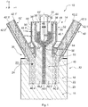
- Fig.1 shows, in a transversal cross-section, a shaft smelt reduction furnace 10 equipped with an embodiment of the present charging system.
- the longitudinal, transversal and vertical axes (X, Y, Z) are presented in the figures mainly for ease of explanation.
- Such furnace 10 is a type of shaft furnace, where it is conventionally distinguished between the lower shaft region formed by a smelt reduction vessel 12 and the upper shaft region formed by a charging system, generally indicated at 14, arranged on the vessel 12.
- the smelt reduction vessel 12 conventionally includes a bottom wall 16, forming the furnace hearth, and lateral walls 18. In practice, these walls consist of an outer metallic envelope 20 internally covered by a ceramic wear lining 22. Vessel 12 is typically of rectangular cross section as seen in a horizontal plane, i.e. in plane (X, Y). It may be noted that the cross-section view of Fig.1 is a vertical cross section view along the width of the furnace, meaning that the length axis of the furnace (length axis of the vessel) is parallel to axis X in the drawing.
- the vessel 12 thus comprises two longitudinal walls 18 extending along the furnace length axis and two end walls 18' (in Fig.2 ), perpendicular to the length axis. These walls define an interior volume of generally rectangular parallelpipedic shape, the interior top edges of these walls defining the rectangular charge opening 23 at the top of vessel 12.
- vessel 12 further includes a number of tuyeres, materialized by arrows 24, for injecting hot air blasts in the lower shaft region; as well as one or more tap holes (not shown) for extracting the hot metal.
- the shaft smelt reduction vessel 12 is only briefly described herein since it is not the focus of the invention and can be of conventional and/or of any appropriate design.
- the charging system 14 comprises a frame structure 30 that is mounted on the vessel opening 23 defined by the top edges of the furnace walls 18, 18'.
- the frame structure 30 supports a center shaft arrangement 32 configured to extract gases from the vessel interior and for introducing material, namely meltdown material, into the furnace.
- the center shaft arrangement 32 extends along the furnace length axis X and comprises:
- the center shaft arrangement 32 is designed to form a vertical stack 40 of materials in the shaft furnace 10, comprising several columns of material.
- a pair of lateral feeders 42, 42', one on each side of the center shaft arrangement 14, is advantageously provided to introduce a third material into the furnace.
- iron bearing material is typically fed into the second feed channels 38, 38'.
- Reducing material mainly carbonaceous material, is introduced via the first feed channels 36, 36' and the lateral feeders 42, 42'.
- the stack 40 is shown schematically as extending vertically over the whole furnace height.
- the lower shaft region contains molten metal.
- the fuel (reducing/carbonaceous material) and iron bearing material are preheated and partially reduced in the upper shaft region.
- the charge is then melted under a reducing atmosphere in the central melting zone.
- Final reduction of residual iron oxides occurs as well slagging of gangue and ashes proceeds in the lower shaft region.
- Metal and slag droplets super heat and accumulate in the hearth.
- the configuration of the center shaft arrangement 14 and lateral feeders 42, 42' allows forming into the furnace a stack 40 of material comprising a central column 40.1 that results from the material flowing through the first feed channels 36, 36' and further through central feed opening 56.
- Central material column 40.1 is in-between two columns 40.2 and 40.3, which are each formed by the material flowing through the second feed channels 38' and 38, respectively.. The latter are in turn between two material columns 40.4 and 40.5 that are adjacent the longitudinal furnace walls 18 and result from the material introduced via lateral feeders 42' and 42.
- the materials for the five columns can be distributed as follows:
- pig iron columns 40.2 and 40.3 will mainly consist of iron ore and other iron bearing materials.
- the pair of columns (40.2, 40.3), resp. (40.4, 40.5) can be fed with the same materials or with different materials, as indicated above.
- each column of material extends over the whole length of the vessel interior, as defined by vessel walls 18 and 18'.
- the center shaft arrangement 32 comprises a number of longitudinally extending walls that define the various feed channels and the off-gas passage, and that are supported by the frame structure 30.
- the center hood 34 comprises two facing off-gas panels 44, 44' that define a central off-gas duct or channel 46 to evacuate gases rising from the furnace interior.
- Off-gas panels 44, 44' are sensibly vertically arranged, and preferably straight.
- the center hood 34 has a top cover 34.1 (in Fig.2 ) closing the off-gas duct and provided a top opening for extraction piping (not shown).
- Two partition walls 48, 48' are arranged on the sides of center hood 34 and cooperate with off-gas panels 44, 44' to define the first feed channels 36, 36'.
- the partition walls 48, 48' cooperate also with further laterally arranged outer walls 50, 50' to define the second feed channels 38, 38'.
- the outer walls 50, 50' generally extend vertically; the upper portion is straight and parallel to the facing portion of the respective partition wall 48, 48'.
- outer walls 50, 50' are connected with the frame structure 30, defining a rectangular upper shaft passage 52 that is vertically aligned with the vessel opening 23.
- the lateral feeders 42, 42' each include a pair of walls 42.1, 42.2 and 42.1', 42.2', which are here straight, inclined walls extending parallel to one another.
- Feeder wall 42.1, resp. 42.1' is connected to the frame 30 below the charge passage 52, i.e. downstream of the center shaft arrangement 14.
- the cooperating feeder wall 42.2, resp. 42.2' is also connected to the frame structure 30, but spaced from the other feeder wall to define the feed passage there-between that opens into the furnace and more precisely directly into the upper area of vessel 12, i.e. below the center shaft arrangement.
- the vessel walls 18, 18' as well as the walls 44, 48, 50... of the charging system 12 may be provided with internal cooling pipes/channels, typically arranged in the refractory lining, for circulating a coolant fluid.
- partition walls 48, 48' comprise lower wall portions 54, 54' that extend towards each other below the center hood 34 to define a center feed passage 56.
- material descending through the first feed channels 38, 38' may, before flowing through the center feed passage 56, accumulate on the lower portions 54, 54' according to the angle of repose of the granular material, thereby permitting self-adjustment of the first material stock-line, indicated 60, in the shaft arrangement 14.
- the partition walls 48, 48' have straight upper portions 48.1, 48.1' and inclined lower portions 54, 54' converging towards the center of the furnace.
- the partition walls 48, 48' thus form a kind of funnel, in which the center hood 34 is arranged.
- the center hood 34 defines, with the upper region 48.1, 48.1' of the partition walls, the first feed channels 36, 36'.
- There the granular material is constrained between the cooperating walls. But once the granular material passes beyond/downstream the lower edges of the off-gas panels 48, 48', it is no longer vertically constrained by the latter.
- the granular material may thus freely accumulate on the beveled surfaces offered by lower partition walls 54, 54', where it will actually accumulate according to the angle of repose of the granular material.
- angle of repose' is used herein according to its conventional meaning. That is, having regard to granular material, the angle of repose designates the maximum angle of a stable slope of a pile of such granular material. For example, when bulk granular material is poured onto a horizontal base surface, a conical pile forms. The internal angle between the surface of the pile and the base surface is known as the angle of repose; essentially, the angle of repose is the angle a pile forms with the horizontal.
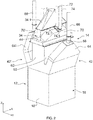
- the shaft furnace 10 is shown in perspective in Fig.2 .
- the charging system 14 is designed as a gas-tight structure on top of vessel 12, connected to piping for evacuating off-gases and for supplying the respective feed channels.
- the whole center shaft arrangement 32, as well as the lateral feeders 42, 42' are advantageously enclosed in a metallic envelope.
- This envelope in internally covered with a refractory liner, thereby forming the outer walls 50, 50' as well as the walls of the lateral feeders 42, 42'.
- two opposite transversally (Y, Z plane) extending end walls 62 correspond (only one can be seen) to the end walls 18' of the furnace vessel and thus delimit the longitudinal extent of the center shaft arrangement 32, first and second feed channels and of the lateral feeders.
- This design makes it clear that all channels defined by said walls are open upwards and have a rectangular flow cross-section.
- each lateral feeder 42 is closed by a respective cover 64.
- Material here coal, arrives therein from above via pipes 66 that are in communication with material supply means (not shown).
- Each pipe 66 opens into the respective cover 64, 64' at a charging point 68.
- a cover 70, 70' is arranged on each side of the center shaft arrangement 32 to cover the first and second channels 36, 36', 38 and 38'.
- An internal partition separates each cover 70, 70' into two regions so that pipes 72 communicate with the first channels 36, 36' and pipes 74 communicate with the second channels 38, 38'.
- each of these pipes 72 and 74 are connected to respective charging points 72.1 and 74.1 in the cover and, at their upper ends, with material supply means.
- each pipe or pair of pipes has its upper end in communication with a proportioning valve located downstream of a material hopper, generally via intermediate an intermediate bin and seal valves (not shown).
- the material is simply charged in the respective feed channels via the pipes into covers 64 and 70, without movable tubes or chutes.
- the material falls from the pipes into the respective covers and further in the corresponding feed channels; under its natural gravitary flow, the granular material tends to form a triangular heap.
- Several charging points can be provided in each cover, if desired, in particular for furnaces of greater length.
- the charging level in the respective feed channels can be monitored by means of radars, as is known in the art, or by any other appropriate system.
- iron bearing material is typically introduced as the second material, i.e. in the second feed channels (material 2 and 3 as described before).
- the iron bearing material is of granular form, typically with a particle size in ranging from 5 to 300 mm.
- the iron bearing material can be preliminarily formed into agglomerates, pellets, briquettes or the like, during hot or cold processing, using binders and/or additives.
- the agglomerates may further contain reducing material, in particular to form self-reducing agglomerates.
- Carbonaceous material is charge into the furnace via the first feed channels and the lateral feeders, e.g. using material such as materials 1, 4 and 5 described above
- the Carbonaceous material loaded into lateral feeders 42, 42' may have a size of 5 to 300 mm.
- the charge level may be monitored in the respective channels by means of radars, as mentioned above.
- the stock-line level of the center material column adjusts itself based on the angle of repose of this material. This guarantees a constant stock-line level over the whole furnace length.
- the present charging system thus permits the building of a central column of material 1, which improves the efficiency of the thermal exchange between the ascending gasses and the charge by minimizing the wall effect. Furthermore, it ensures a constant and homogeneous charging level, which is beneficial in terms of permeability and distribution of the gasses.
- a minimum and maximum charge levels for channels 36, 36' and 38, 38' are indicated Lmin and Lmax. This represents the base of the respective heap of material formed in the channels and further in the corresponding covers.
- the stock-line level 60 adjusts itself based on the angle of repose of the material residing on the lower portions 54, 54' of partition walls 48, 48', it is independent of the charge level in the channels 36 and 36'.
- the stock-line level 60 can be modified by changing the distance D between the lower edge of off-gas panels 44, 44' and the corresponding lower portions 36 and 36'. Therefore, off-gas panels 44 and 44' are preferably constructed as removable walls or as segmented walls, such that the lower portion can e.g. be replaced by another, longer or shorter wall portion. As it will be understood, increasing distance D will increase the stock-line level 60.
Landscapes
- Engineering & Computer Science (AREA)
- Chemical & Material Sciences (AREA)
- Manufacturing & Machinery (AREA)
- Materials Engineering (AREA)
- Metallurgy (AREA)
- Organic Chemistry (AREA)
- Mechanical Engineering (AREA)
- General Engineering & Computer Science (AREA)
- Vertical, Hearth, Or Arc Furnaces (AREA)
- Furnace Details (AREA)
- Manufacture Of Iron (AREA)
- Furnace Charging Or Discharging (AREA)
Claims (9)
- Système de chargement pour four à cuve de fusion-réduction, comprenant :une structure formant cadre (30) destinée à être montée sur une ouverture de charge supérieure d'une cuve de fusion-réduction (12) ;un agencement de conduit central (32) supporté par ladite structure formant cadre (30) et configuré pour éliminer les gaz émis par le four et pour introduire des matériaux de charge granulaires afin de former une pile (40) de matériaux dans le four, ledit agencement de conduit central comprenant :- une hotte centrale (34) pour l'extraction des gaz émis ;- une paire de premiers canaux d'alimentation (36, 36') pour un premier matériau, un sur chaque côté de ladite hotte centrale ; et- une paire de seconds canaux d'alimentation (38, 38') pour un second matériau, situés sur des côtés respectifs desdits premiers canaux d'alimentation ;ladite hotte centrale comprenant une paire de panneaux d'évacuation des gaz (44, 44') se faisant face définissant un canal d'évacuation des gaz (46), chaque panneau d'évacuation des gaz coopérant avec une paroi de séparation (48, 48') respective pour définir un premier canal d'alimentation (36, 36') respectif ; etchaque paroi de séparation (48, 48') coopérant avec une paroi extérieure (50, 50') respective pour définir un second canal d'alimentation (38, 38') respectif ;les parois de séparation (48, 48') comportant des parties inférieures (54, 54') qui s'étendent l'une vers l'autre sous ladite hotte centrale (34) pour définir un passage d'alimentation central (56), grâce à quoi le matériau descendant à travers lesdits premiers canaux d'alimentation peut, avant de s'écouler à travers ledit passage d'alimentation central, s'accumuler sur lesdites parties inférieures (54, 54') en fonction de l'angle de talus naturel dudit matériau, ce qui permet un réglage automatique du niveau de premier matériau dans l'agencement de conduit central.
- Système de chargement selon la revendication 1, dans lequel chaque paroi de séparation (48, 48') comporte une partie supérieure droite (48.1, 48.1'), de préférence verticale, qui est reliée auxdites parties inférieures ; et lesdites parties inférieures (54, 54') desdites parois de séparation s'étendent plus bas que lesdits panneaux d'évacuation des gaz (44, 44') et sous ledit canal d'évacuation des gaz (46), ledit passage d'alimentation central (56) ayant une section d'écoulement plus étroite que ledit canal d'évacuation des gaz (46).
- Système de chargement selon l'une quelconque des revendications précédentes, comprenant deux chargeurs latéraux (42, 42'), chacun monté sur ladite structure formant cadre et débouchant dans ledit four en aval dudit agencement de conduit central.
- Système de chargement selon l'une quelconque des revendications précédentes, dans lequel lesdites parois extérieures (50, 50') comportent chacune une partie inférieure se reliant audit cadre pour définir un passage de charge, en aval dudit passage d'alimentation central, qui est aligné verticalement avec l'ouverture de charge supérieure de la cuve.
- Système de chargement selon la revendication 4, dans lequel la partie inférieure de chaque paroi extérieure comprend une section se rétrécissant vers l'intérieur et une section verticale qui est positionnée en alignement vertical avec le panneau d'évacuation des gaz respectif ou plus à l'intérieur.
- Système de chargement selon l'une quelconque des revendications précédentes, dans lequel lesdits panneaux d'évacuation des gaz (44, 44') sont montés de manière amovible dans ladite hotte centrale (34) afin de permettre un réglage de la zone d'écoulement entre les arêtes inférieures des panneaux d'évacuation des gaz et les parties inférieures correspondantes des parois de séparation.
- Système de chargement selon l'une quelconque des revendications précédentes, dans lequel un couvercle (70) ferme une ouverture supérieure de chacun desdits premiers et seconds canaux d'alimentation, chacun desdits couvercles comportant au moins un point de chargement permettant une connexion à un système d'alimentation de matériaux.
- Four à cuve de fusion-réduction comprenant de ladite cuve de fusion-réduction (12) et un système de chargement selon l'une quelconque des revendications précédentes monté sur une ouverture de chargement supérieure.
- Four à cuve de fusion-réduction selon la revendication 8, dans lequel ladite cuve de fusion-réduction (12) est de section généralement rectangulaire.
Priority Applications (1)
| Application Number | Priority Date | Filing Date | Title |
|---|---|---|---|
| PL18811569T PL3720976T3 (pl) | 2017-12-07 | 2018-12-06 | Układ ładowania, w szczególności dla pieca szybowego do wytapiania redukcyjnego |
Applications Claiming Priority (2)
| Application Number | Priority Date | Filing Date | Title |
|---|---|---|---|
| LU100535A LU100535B1 (en) | 2017-12-07 | 2017-12-07 | Charging system, in particular for a shaft smelt reduction furnace |
| PCT/EP2018/083843 WO2019110748A1 (fr) | 2017-12-07 | 2018-12-06 | Système de chargement, en particulier pour un four de réduction-fusion à arbre |
Publications (2)
| Publication Number | Publication Date |
|---|---|
| EP3720976A1 EP3720976A1 (fr) | 2020-10-14 |
| EP3720976B1 true EP3720976B1 (fr) | 2021-08-25 |
Family
ID=60972299
Family Applications (1)
| Application Number | Title | Priority Date | Filing Date |
|---|---|---|---|
| EP18811569.5A Active EP3720976B1 (fr) | 2017-12-07 | 2018-12-06 | Système de chargement, en particulier pour un four de réduction-fusion à arbre |
Country Status (12)
| Country | Link |
|---|---|
| US (1) | US11542565B2 (fr) |
| EP (1) | EP3720976B1 (fr) |
| JP (1) | JP2021505838A (fr) |
| KR (1) | KR20200093038A (fr) |
| CN (1) | CN111511932B (fr) |
| AU (1) | AU2018379528A1 (fr) |
| BR (1) | BR112020011200B1 (fr) |
| EA (1) | EA038817B1 (fr) |
| LU (1) | LU100535B1 (fr) |
| PL (1) | PL3720976T3 (fr) |
| UA (1) | UA126822C2 (fr) |
| WO (1) | WO2019110748A1 (fr) |
Families Citing this family (4)
| Publication number | Priority date | Publication date | Assignee | Title |
|---|---|---|---|---|
| LU100535B1 (en) * | 2017-12-07 | 2019-06-12 | Wurth Paul Sa | Charging system, in particular for a shaft smelt reduction furnace |
| LU101960B1 (en) | 2020-07-28 | 2022-01-28 | Wurth Paul Sa | Method for operating a metallurgic plant for producing iron products |
| BR102021000742A2 (pt) | 2021-01-15 | 2022-07-26 | Tecnored Desenvolvimento Tecnologico S.A. | Sistema e método de distribuição de cargas em um forno metalúrgico |
| WO2024216354A1 (fr) * | 2023-04-20 | 2024-10-24 | Tecnored Desenvolvimento Tecnologico S.A. | Four métallurgique |
Family Cites Families (19)
| Publication number | Priority date | Publication date | Assignee | Title |
|---|---|---|---|---|
| DE194613C (fr) * | ||||
| US1945341A (en) | 1931-08-27 | 1934-01-30 | Brassert & Co | Reduction and smelting of ores |
| US3594154A (en) * | 1967-05-20 | 1971-07-20 | Sumitomo Metal Ind | Iron making process and its arrangement thereof |
| GB1176740A (en) * | 1968-03-07 | 1970-01-07 | Tsnii Chernoj Metallurg | A Method of and a Shaft Furnace for Making Spongy Metal. |
| JPH0694567B2 (ja) * | 1991-06-03 | 1994-11-24 | 石川島播磨重工業株式会社 | 原料装入装置 |
| LU88429A1 (fr) | 1993-11-23 | 1995-07-10 | Wurth Paul Sa | Dispositif de chargement d'un four à cuve |
| RU2136762C1 (ru) | 1998-03-20 | 1999-09-10 | Закрытое акционерное общество Научно-производственный и коммерческий центр "ТОТЕМ" | Устройство для загрузки шахтной печи |
| LU90293B1 (fr) * | 1998-10-06 | 2000-04-07 | Wurth Paul Sa | Procédé pour l'enfournement de fines ou de granulés dans un four à arc |
| US6692688B2 (en) | 2001-03-20 | 2004-02-17 | Startec Iron, Llc | Modular furnace |
| US6517603B2 (en) | 2001-03-20 | 2003-02-11 | Startec Iron Llc | Method for recovery of metals having low vaporization temperature |
| US6800113B2 (en) * | 2001-06-28 | 2004-10-05 | Startec Iron Llc | Equipment for distribution and feeding of charge and fuel in shaft furnaces of rectangular cross section |
| KR100948929B1 (ko) | 2007-12-24 | 2010-03-23 | 주식회사 포스코 | 환원로 및 이를 포함하는 용철 제조 장치 |
| JP5166213B2 (ja) * | 2008-11-11 | 2013-03-21 | 株式会社ナニワ炉機研究所 | 溶融炉 |
| LU91645B1 (en) * | 2010-01-27 | 2011-07-28 | Wurth Paul Sa | A charging device for a metallurgical reactor |
| AT511738B1 (de) | 2011-07-21 | 2013-04-15 | Siemens Vai Metals Tech Gmbh | Schmelzreduktionsaggregat und verfahren zum betrieb eines schmelzreduktionsaggregats |
| BR102015005373A2 (pt) * | 2014-12-16 | 2016-10-25 | Tecnored Desenvolvimento Tecnologico S A | forno metalúrgico de obtenção de ligas metálicas |
| CN104634100B (zh) * | 2015-02-13 | 2017-01-18 | 阳谷祥光铜业有限公司 | 一种旋浮熔炼方法、喷嘴和冶金设备 |
| CN105112684A (zh) * | 2015-10-05 | 2015-12-02 | 杨伟燕 | 一种旋浮冶炼喷嘴 |
| LU100535B1 (en) * | 2017-12-07 | 2019-06-12 | Wurth Paul Sa | Charging system, in particular for a shaft smelt reduction furnace |
-
2017
- 2017-12-07 LU LU100535A patent/LU100535B1/en active IP Right Grant
-
2018
- 2018-12-06 UA UAA202003963A patent/UA126822C2/uk unknown
- 2018-12-06 AU AU2018379528A patent/AU2018379528A1/en not_active Abandoned
- 2018-12-06 PL PL18811569T patent/PL3720976T3/pl unknown
- 2018-12-06 CN CN201880078795.4A patent/CN111511932B/zh active Active
- 2018-12-06 BR BR112020011200-3A patent/BR112020011200B1/pt active IP Right Grant
- 2018-12-06 JP JP2020531024A patent/JP2021505838A/ja not_active Ceased
- 2018-12-06 US US16/767,014 patent/US11542565B2/en active Active
- 2018-12-06 WO PCT/EP2018/083843 patent/WO2019110748A1/fr not_active Ceased
- 2018-12-06 EP EP18811569.5A patent/EP3720976B1/fr active Active
- 2018-12-06 EA EA202091371A patent/EA038817B1/ru unknown
- 2018-12-06 KR KR1020207019536A patent/KR20200093038A/ko not_active Ceased
Also Published As
| Publication number | Publication date |
|---|---|
| JP2021505838A (ja) | 2021-02-18 |
| CN111511932B (zh) | 2022-08-05 |
| EP3720976A1 (fr) | 2020-10-14 |
| EA038817B1 (ru) | 2021-10-25 |
| BR112020011200B1 (pt) | 2023-03-28 |
| BR112020011200A2 (pt) | 2020-11-17 |
| LU100535B1 (en) | 2019-06-12 |
| KR20200093038A (ko) | 2020-08-04 |
| CN111511932A (zh) | 2020-08-07 |
| WO2019110748A1 (fr) | 2019-06-13 |
| EA202091371A1 (ru) | 2020-09-02 |
| US20200318207A1 (en) | 2020-10-08 |
| UA126822C2 (uk) | 2023-02-08 |
| AU2018379528A1 (en) | 2020-07-02 |
| PL3720976T3 (pl) | 2022-01-10 |
| US11542565B2 (en) | 2023-01-03 |
Similar Documents
| Publication | Publication Date | Title |
|---|---|---|
| EP3720976B1 (fr) | Système de chargement, en particulier pour un four de réduction-fusion à arbre | |
| JP4143410B2 (ja) | コークス炉煙道ガス共用 | |
| KR101355325B1 (ko) | 고로 조업 방법 | |
| AU2021202096B2 (en) | Metallurgical furnace for producing metal alloys | |
| US20030047038A1 (en) | Method and apparatus for metal smelting | |
| JPS61502899A (ja) | 連続製鋼法および装置 | |
| JPWO2013179541A1 (ja) | ベルレス高炉への原料装入方法 | |
| US12545970B2 (en) | Production method of pig iron | |
| US20020000687A1 (en) | Method of producing reduced iron and production facilities therefor | |
| CN117295826A (zh) | 生铁制造方法以及矿石原料 | |
| WO2009034544A2 (fr) | Four de réduction à pente statique | |
| JP5862514B2 (ja) | スクラップ溶解竪型炉の操業方法 | |
| JP2019127615A (ja) | 高炉の原料装入方法 | |
| JPH07197114A (ja) | コークス充填層方式の竪型製錬炉 | |
| CN121931303A (zh) | 一种dri粉料炼钢装置和方法 | |
| JP2014015653A (ja) | 銑鉄製造方法及び銑鉄製造炉 | |
| WO2011135485A1 (fr) | Procédé et appareil pour préparer du fer à faible teneur en phosphore | |
| JPS59113109A (ja) | 溶融還元炉の原料装入方法と装置 |
Legal Events
| Date | Code | Title | Description |
|---|---|---|---|
| STAA | Information on the status of an ep patent application or granted ep patent |
Free format text: STATUS: UNKNOWN |
|
| STAA | Information on the status of an ep patent application or granted ep patent |
Free format text: STATUS: THE INTERNATIONAL PUBLICATION HAS BEEN MADE |
|
| PUAI | Public reference made under article 153(3) epc to a published international application that has entered the european phase |
Free format text: ORIGINAL CODE: 0009012 |
|
| STAA | Information on the status of an ep patent application or granted ep patent |
Free format text: STATUS: REQUEST FOR EXAMINATION WAS MADE |
|
| 17P | Request for examination filed |
Effective date: 20200602 |
|
| AK | Designated contracting states |
Kind code of ref document: A1 Designated state(s): AL AT BE BG CH CY CZ DE DK EE ES FI FR GB GR HR HU IE IS IT LI LT LU LV MC MK MT NL NO PL PT RO RS SE SI SK SM TR |
|
| AX | Request for extension of the european patent |
Extension state: BA ME |
|
| DAV | Request for validation of the european patent (deleted) | ||
| DAX | Request for extension of the european patent (deleted) | ||
| GRAP | Despatch of communication of intention to grant a patent |
Free format text: ORIGINAL CODE: EPIDOSNIGR1 |
|
| STAA | Information on the status of an ep patent application or granted ep patent |
Free format text: STATUS: GRANT OF PATENT IS INTENDED |
|
| RIC1 | Information provided on ipc code assigned before grant |
Ipc: C21B 7/02 20060101ALI20210301BHEP Ipc: C21B 13/02 20060101ALI20210301BHEP Ipc: F27D 3/00 20060101ALI20210301BHEP Ipc: F27B 1/20 20060101ALI20210301BHEP Ipc: C21B 5/00 20060101AFI20210301BHEP Ipc: F27B 1/00 20060101ALI20210301BHEP Ipc: C21B 7/00 20060101ALI20210301BHEP |
|
| INTG | Intention to grant announced |
Effective date: 20210325 |
|
| GRAS | Grant fee paid |
Free format text: ORIGINAL CODE: EPIDOSNIGR3 |
|
| GRAA | (expected) grant |
Free format text: ORIGINAL CODE: 0009210 |
|
| STAA | Information on the status of an ep patent application or granted ep patent |
Free format text: STATUS: THE PATENT HAS BEEN GRANTED |
|
| AK | Designated contracting states |
Kind code of ref document: B1 Designated state(s): AL AT BE BG CH CY CZ DE DK EE ES FI FR GB GR HR HU IE IS IT LI LT LU LV MC MK MT NL NO PL PT RO RS SE SI SK SM TR |
|
| REG | Reference to a national code |
Ref country code: CH Ref legal event code: EP |
|
| REG | Reference to a national code |
Ref country code: IE Ref legal event code: FG4D Ref country code: AT Ref legal event code: REF Ref document number: 1423853 Country of ref document: AT Kind code of ref document: T Effective date: 20210915 |
|
| REG | Reference to a national code |
Ref country code: DE Ref legal event code: R096 Ref document number: 602018022556 Country of ref document: DE |
|
| REG | Reference to a national code |
Ref country code: FI Ref legal event code: FGE |
|
| REG | Reference to a national code |
Ref country code: SE Ref legal event code: TRGR |
|
| REG | Reference to a national code |
Ref country code: LT Ref legal event code: MG9D |
|
| REG | Reference to a national code |
Ref country code: NL Ref legal event code: MP Effective date: 20210825 |
|
| REG | Reference to a national code |
Ref country code: AT Ref legal event code: MK05 Ref document number: 1423853 Country of ref document: AT Kind code of ref document: T Effective date: 20210825 |
|
| REG | Reference to a national code |
Ref country code: NO Ref legal event code: T2 Effective date: 20210825 |
|
| PG25 | Lapsed in a contracting state [announced via postgrant information from national office to epo] |
Ref country code: ES Free format text: LAPSE BECAUSE OF FAILURE TO SUBMIT A TRANSLATION OF THE DESCRIPTION OR TO PAY THE FEE WITHIN THE PRESCRIBED TIME-LIMIT Effective date: 20210825 Ref country code: RS Free format text: LAPSE BECAUSE OF FAILURE TO SUBMIT A TRANSLATION OF THE DESCRIPTION OR TO PAY THE FEE WITHIN THE PRESCRIBED TIME-LIMIT Effective date: 20210825 Ref country code: LT Free format text: LAPSE BECAUSE OF FAILURE TO SUBMIT A TRANSLATION OF THE DESCRIPTION OR TO PAY THE FEE WITHIN THE PRESCRIBED TIME-LIMIT Effective date: 20210825 Ref country code: AT Free format text: LAPSE BECAUSE OF FAILURE TO SUBMIT A TRANSLATION OF THE DESCRIPTION OR TO PAY THE FEE WITHIN THE PRESCRIBED TIME-LIMIT Effective date: 20210825 Ref country code: BG Free format text: LAPSE BECAUSE OF FAILURE TO SUBMIT A TRANSLATION OF THE DESCRIPTION OR TO PAY THE FEE WITHIN THE PRESCRIBED TIME-LIMIT Effective date: 20211125 Ref country code: PT Free format text: LAPSE BECAUSE OF FAILURE TO SUBMIT A TRANSLATION OF THE DESCRIPTION OR TO PAY THE FEE WITHIN THE PRESCRIBED TIME-LIMIT Effective date: 20211227 Ref country code: HR Free format text: LAPSE BECAUSE OF FAILURE TO SUBMIT A TRANSLATION OF THE DESCRIPTION OR TO PAY THE FEE WITHIN THE PRESCRIBED TIME-LIMIT Effective date: 20210825 |
|
| PG25 | Lapsed in a contracting state [announced via postgrant information from national office to epo] |
Ref country code: LV Free format text: LAPSE BECAUSE OF FAILURE TO SUBMIT A TRANSLATION OF THE DESCRIPTION OR TO PAY THE FEE WITHIN THE PRESCRIBED TIME-LIMIT Effective date: 20210825 Ref country code: GR Free format text: LAPSE BECAUSE OF FAILURE TO SUBMIT A TRANSLATION OF THE DESCRIPTION OR TO PAY THE FEE WITHIN THE PRESCRIBED TIME-LIMIT Effective date: 20211126 |
|
| PG25 | Lapsed in a contracting state [announced via postgrant information from national office to epo] |
Ref country code: NL Free format text: LAPSE BECAUSE OF FAILURE TO SUBMIT A TRANSLATION OF THE DESCRIPTION OR TO PAY THE FEE WITHIN THE PRESCRIBED TIME-LIMIT Effective date: 20210825 |
|
| PG25 | Lapsed in a contracting state [announced via postgrant information from national office to epo] |
Ref country code: DK Free format text: LAPSE BECAUSE OF FAILURE TO SUBMIT A TRANSLATION OF THE DESCRIPTION OR TO PAY THE FEE WITHIN THE PRESCRIBED TIME-LIMIT Effective date: 20210825 |
|
| REG | Reference to a national code |
Ref country code: DE Ref legal event code: R097 Ref document number: 602018022556 Country of ref document: DE |
|
| PG25 | Lapsed in a contracting state [announced via postgrant information from national office to epo] |
Ref country code: SM Free format text: LAPSE BECAUSE OF FAILURE TO SUBMIT A TRANSLATION OF THE DESCRIPTION OR TO PAY THE FEE WITHIN THE PRESCRIBED TIME-LIMIT Effective date: 20210825 Ref country code: SK Free format text: LAPSE BECAUSE OF FAILURE TO SUBMIT A TRANSLATION OF THE DESCRIPTION OR TO PAY THE FEE WITHIN THE PRESCRIBED TIME-LIMIT Effective date: 20210825 Ref country code: RO Free format text: LAPSE BECAUSE OF FAILURE TO SUBMIT A TRANSLATION OF THE DESCRIPTION OR TO PAY THE FEE WITHIN THE PRESCRIBED TIME-LIMIT Effective date: 20210825 Ref country code: EE Free format text: LAPSE BECAUSE OF FAILURE TO SUBMIT A TRANSLATION OF THE DESCRIPTION OR TO PAY THE FEE WITHIN THE PRESCRIBED TIME-LIMIT Effective date: 20210825 Ref country code: CZ Free format text: LAPSE BECAUSE OF FAILURE TO SUBMIT A TRANSLATION OF THE DESCRIPTION OR TO PAY THE FEE WITHIN THE PRESCRIBED TIME-LIMIT Effective date: 20210825 Ref country code: AL Free format text: LAPSE BECAUSE OF FAILURE TO SUBMIT A TRANSLATION OF THE DESCRIPTION OR TO PAY THE FEE WITHIN THE PRESCRIBED TIME-LIMIT Effective date: 20210825 |
|
| PLBE | No opposition filed within time limit |
Free format text: ORIGINAL CODE: 0009261 |
|
| REG | Reference to a national code |
Ref country code: DE Ref legal event code: R119 Ref document number: 602018022556 Country of ref document: DE |
|
| STAA | Information on the status of an ep patent application or granted ep patent |
Free format text: STATUS: NO OPPOSITION FILED WITHIN TIME LIMIT |
|
| PG25 | Lapsed in a contracting state [announced via postgrant information from national office to epo] |
Ref country code: MC Free format text: LAPSE BECAUSE OF FAILURE TO SUBMIT A TRANSLATION OF THE DESCRIPTION OR TO PAY THE FEE WITHIN THE PRESCRIBED TIME-LIMIT Effective date: 20210825 Ref country code: IT Free format text: LAPSE BECAUSE OF FAILURE TO SUBMIT A TRANSLATION OF THE DESCRIPTION OR TO PAY THE FEE WITHIN THE PRESCRIBED TIME-LIMIT Effective date: 20210825 |
|
| REG | Reference to a national code |
Ref country code: CH Ref legal event code: PL |
|
| 26N | No opposition filed |
Effective date: 20220527 |
|
| PG25 | Lapsed in a contracting state [announced via postgrant information from national office to epo] |
Ref country code: SI Free format text: LAPSE BECAUSE OF FAILURE TO SUBMIT A TRANSLATION OF THE DESCRIPTION OR TO PAY THE FEE WITHIN THE PRESCRIBED TIME-LIMIT Effective date: 20210825 |
|
| REG | Reference to a national code |
Ref country code: BE Ref legal event code: MM Effective date: 20211231 |
|
| PG25 | Lapsed in a contracting state [announced via postgrant information from national office to epo] |
Ref country code: LU Free format text: LAPSE BECAUSE OF NON-PAYMENT OF DUE FEES Effective date: 20211206 Ref country code: IE Free format text: LAPSE BECAUSE OF NON-PAYMENT OF DUE FEES Effective date: 20211206 Ref country code: DE Free format text: LAPSE BECAUSE OF NON-PAYMENT OF DUE FEES Effective date: 20220701 |
|
| PG25 | Lapsed in a contracting state [announced via postgrant information from national office to epo] |
Ref country code: FR Free format text: LAPSE BECAUSE OF NON-PAYMENT OF DUE FEES Effective date: 20211231 Ref country code: BE Free format text: LAPSE BECAUSE OF NON-PAYMENT OF DUE FEES Effective date: 20211231 |
|
| PG25 | Lapsed in a contracting state [announced via postgrant information from national office to epo] |
Ref country code: LI Free format text: LAPSE BECAUSE OF NON-PAYMENT OF DUE FEES Effective date: 20211231 Ref country code: CH Free format text: LAPSE BECAUSE OF NON-PAYMENT OF DUE FEES Effective date: 20211231 |
|
| PGFP | Annual fee paid to national office [announced via postgrant information from national office to epo] |
Ref country code: TR Payment date: 20221201 Year of fee payment: 5 Ref country code: SE Payment date: 20221221 Year of fee payment: 5 Ref country code: NO Payment date: 20221220 Year of fee payment: 5 Ref country code: FI Payment date: 20221216 Year of fee payment: 5 |
|
| PGFP | Annual fee paid to national office [announced via postgrant information from national office to epo] |
Ref country code: PL Payment date: 20221128 Year of fee payment: 5 |
|
| P01 | Opt-out of the competence of the unified patent court (upc) registered |
Effective date: 20230524 |
|
| PG25 | Lapsed in a contracting state [announced via postgrant information from national office to epo] |
Ref country code: CY Free format text: LAPSE BECAUSE OF FAILURE TO SUBMIT A TRANSLATION OF THE DESCRIPTION OR TO PAY THE FEE WITHIN THE PRESCRIBED TIME-LIMIT Effective date: 20210825 |
|
| PG25 | Lapsed in a contracting state [announced via postgrant information from national office to epo] |
Ref country code: HU Free format text: LAPSE BECAUSE OF FAILURE TO SUBMIT A TRANSLATION OF THE DESCRIPTION OR TO PAY THE FEE WITHIN THE PRESCRIBED TIME-LIMIT; INVALID AB INITIO Effective date: 20181206 |
|
| GBPC | Gb: european patent ceased through non-payment of renewal fee |
Effective date: 20221206 |
|
| PG25 | Lapsed in a contracting state [announced via postgrant information from national office to epo] |
Ref country code: GB Free format text: LAPSE BECAUSE OF NON-PAYMENT OF DUE FEES Effective date: 20221206 |
|
| PG25 | Lapsed in a contracting state [announced via postgrant information from national office to epo] |
Ref country code: MK Free format text: LAPSE BECAUSE OF FAILURE TO SUBMIT A TRANSLATION OF THE DESCRIPTION OR TO PAY THE FEE WITHIN THE PRESCRIBED TIME-LIMIT Effective date: 20210825 |
|
| REG | Reference to a national code |
Ref country code: SE Ref legal event code: EUG |
|
| PG25 | Lapsed in a contracting state [announced via postgrant information from national office to epo] |
Ref country code: FI Free format text: LAPSE BECAUSE OF NON-PAYMENT OF DUE FEES Effective date: 20231206 |
|
| PG25 | Lapsed in a contracting state [announced via postgrant information from national office to epo] |
Ref country code: MT Free format text: LAPSE BECAUSE OF FAILURE TO SUBMIT A TRANSLATION OF THE DESCRIPTION OR TO PAY THE FEE WITHIN THE PRESCRIBED TIME-LIMIT Effective date: 20210825 |
|
| PG25 | Lapsed in a contracting state [announced via postgrant information from national office to epo] |
Ref country code: NO Free format text: LAPSE BECAUSE OF NON-PAYMENT OF DUE FEES Effective date: 20231231 |
|
| PG25 | Lapsed in a contracting state [announced via postgrant information from national office to epo] |
Ref country code: PL Free format text: LAPSE BECAUSE OF NON-PAYMENT OF DUE FEES Effective date: 20231206 |
|
| PG25 | Lapsed in a contracting state [announced via postgrant information from national office to epo] |
Ref country code: SE Free format text: LAPSE BECAUSE OF NON-PAYMENT OF DUE FEES Effective date: 20231207 |