EP3721090B1 - Auslasslamellenventil - Google Patents
Auslasslamellenventil Download PDFInfo
- Publication number
- EP3721090B1 EP3721090B1 EP18833396.7A EP18833396A EP3721090B1 EP 3721090 B1 EP3721090 B1 EP 3721090B1 EP 18833396 A EP18833396 A EP 18833396A EP 3721090 B1 EP3721090 B1 EP 3721090B1
- Authority
- EP
- European Patent Office
- Prior art keywords
- lamella
- bridge
- outlet
- opening
- openings
- Prior art date
- Legal status (The legal status is an assumption and is not a legal conclusion. Google has not performed a legal analysis and makes no representation as to the accuracy of the status listed.)
- Active
Links
Images



Classifications
-
- F—MECHANICAL ENGINEERING; LIGHTING; HEATING; WEAPONS; BLASTING
- F04—POSITIVE - DISPLACEMENT MACHINES FOR LIQUIDS; PUMPS FOR LIQUIDS OR ELASTIC FLUIDS
- F04B—POSITIVE-DISPLACEMENT MACHINES FOR LIQUIDS; PUMPS
- F04B39/00—Component parts, details, or accessories, of pumps or pumping systems specially adapted for elastic fluids, not otherwise provided for in, or of interest apart from, groups F04B25/00 - F04B37/00
- F04B39/10—Adaptations or arrangements of distribution members
- F04B39/1073—Adaptations or arrangements of distribution members the members being reed valves
Definitions
- the invention relates to an outlet lamellar valve, in particular a lamellar valve for closing and opening an outlet opening in a housing of a compression cylinder of a compressor.
- Compressors are used, for example, in the braking systems of buses or trucks. Such compressors have one or more compression cylinders and are attached directly to the engine of the vehicle. Reciprocating compressors which have a duty cycle with suction, compression and discharge of air are often used. When the compressor is in operation, energy is consumed via the vehicle engine on the one hand due to compression work and on the other hand due to mechanical losses, such as friction in the piston rings or throttling losses of a reed valve.
- energy saving is a major challenge.
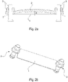
- exhaust reed valves which, as in Fig. 1 , Figures 2a and 2b shown, from a lamella 1, which closes and opens outlet openings 4 of a compression cylinder in a housing 9 of the compression cylinder, from a bridge 2, which restricts deformation of the lamella 1 in an open state of the outlet openings 4, and from fastening elements 3.
- the outlet reed valve blocks the outlet openings 4 in order to prevent pressurized air that has already been expelled from flowing back into the compression cylinder.
- the lamella 1 is bent away from the outlet opening by the air flow in order to allow air to flow out into an outlet channel.
- the maximum radius of curvature of the bent-away lamella 1, which is supported on the bridge 2, is in Fig. 2a given with ⁇ . As stated above, part of the energy of the compressed air is used to bend the lamella 1.
- a valve plate of the housing 9 of the compression cylinder is shown here, which is attached to a cylinder block.
- a separate valve plate is not absolutely necessary and the function of the separate valve plate can be performed by a section integrated in the housing 9 of the compression cylinder.
- JPH04105674U discloses a discharge reed valve for a compressor including a bridge for restricting maximum deformation of the fin with two discharge holes.
- the object on which the invention is based is to provide an outlet lamellar valve which, under given dimensional boundary conditions, reduces a pressure drop at the outlet lamellar valve.
- an outlet lamellar valve according to claim 1. Further developments of the invention are the subject of the dependent claims.
- By providing at least one opening for a fastening element in the lamella it is possible to increase a length of the lamella in order to increase a maximum distance from the lamella to an outlet opening of the compression cylinder with at least approximately the same radius of curvature of the lamella.
- the fastening elements can then attach a bridge, which restricts a maximum deformation of the lamella and thus determines its maximum radius of curvature, at given fastening points inside the lamella, so that no additional space is required for fastening outside the lamella.
- the at least one opening is advantageously arranged in an outer region of the lamella, it is possible to have the outlet opening with respect to the lamella on one Position where the maximum deformation of the lamella is greatest in order to make an outlet area as large as possible.
- two openings are provided in the lamella. This makes it possible to securely attach the bridge with two fastening elements.
- the lamella has an elongated shape, that is to say a shape in which a dimension in a first direction is significantly smaller than a dimension in a second direction perpendicular to the first direction.
- the openings are arranged in the region of ends in a longitudinal direction, that is to say the direction with the large dimension. This makes it possible to securely fasten the bridge with a large support spacing without the openings in the lamella exposing the outlet openings in a closed position of the lamella.
- the bridge has at least one outflow hole, which is arranged in an area that essentially coincides with at least one of the openings of the lamella arranged as intended in the bridge, so that air, in addition to lateral outlet surfaces, through the opening (s) in the lamella can flow out through the outflow hole in the bridge.
- the openings are advantageously open towards the ends in the longitudinal direction. There is the possibility of using the openings with an enlarged cross-sectional area for an improved outflow of air through the outflow hole.
- the opening is arranged in a central area of the lamella, it is possible to fasten the lamella in the central area.
- the lamella can bend upwards at several points in its edge area, whereby, compared to the fastenings in the edge area, both several outlet openings or outlet openings with a larger overall cross-section can be released and the effort for fastening the bridge is reduced, since this Fastener is only required in one place.
- This lamella has an elongated shape so that, when the outlet openings are arranged in the region of the ends in the longitudinal direction, the lever arm for deforming the lamella is large in order to reduce the force for deforming the lamella and thus a pressure drop.
- An anti-twist device prevents the lamella from twisting, so that the outlet openings are securely closed when the lamella is in a closed state.
- the anti-rotation device is provided as an elevation or depression in the lamella and a depression or elevation that is complementary to the elevation or depression in the housing of the compression cylinder.
- An elevation or depression in the lamella can be easily produced by embossing or a similar manufacturing step.
- FIG. 11 shows a side sectional view of an exhaust reed valve
- FIG Figure 3b shows an isometric view of the exhaust reed valve.
- the outlet lamellar valve is provided, outlet openings ( Fig. 1 : Bzz. 4) in one housing ( Fig. 1 : Bzz. 9) to close and open a compression cylinder of a compressor.
- FIG. 3a and 3b shows how the prior art according to the Figures 1 , 2a and 2b , also a lamella 1 for closing and opening an outlet opening not shown here ( Fig. 1 : Bzz. 4) on.
- a single outlet opening can be provided or, alternatively, a plurality of outlet openings, wherein a total cross-sectional area of the outlet openings should be selected as large as possible in order to minimize a pressure loss when the air is expelled.
- the outlet reed valve also has a bridge 2 in order to restrict deformation of the lamella 1.
- the lamella 1 is released by a stream of air through the outlet openings ( Fig. 1 : Bzz. 4) bent upwards until the outlet openings ( Fig. 1 : Bzz. 4) rests on a support surface 5 facing the lamella 1.
- the bridge 2 has in one area a support surface 5 with a predetermined radius of curvature ⁇ which is essentially identical to that in FIG Fig. 2a
- the radius of curvature shown is ⁇ , so that, on the one hand, the largest possible outlet area is realized, but, on the other hand, an increase in bending stresses does not reduce a service life.
- the bridge 2 has a depression (not shown here) through which the lamella 1 is guided laterally in order to restrict the lamella 1 from shifting laterally.
- the bridge 2 also has through holes 8 for fastening elements 3.
- the fastening elements 3 here each consist of bolts and nuts, but can also be designed in a different form, for example as rivets.
- Figure 4a shows an isometric view of the lamella 1 and the fastening elements 3.
- the openings 6 are not here, as in FIG Figure 3b embodiment shown, formed as through holes matched to a dimension of the fastening element 3, but have dimensions described below.
- Figure 4b shows a plan view of an alternative lamella 1.
- the openings 6 in this lamella 1 are open towards the ends in the longitudinal direction.
- the bridge 2 has through outflow holes 7 with predetermined Dimensions on.
- the outflow holes 7 are each provided in an area which essentially coincides with the openings 6 of the lamella 1 arranged as intended in the bridge 2.
- the dimensions of the openings 6 are selected such that they essentially correspond to the predetermined dimensions of the associated outflow holes 7.
- the bridge 2 has the outflow holes 7 in addition to the through holes 8 for the fastening elements 3.
- Figure 5a Figure 3 is an exploded view of the exhaust reed valve according to an embodiment not forming part of the invention.
- the lamella 1 does not have the opening 6 in an outer area of the lamella 1, but the opening 6 through which the fastening element 3 penetrates the lamella 1 is arranged in a central area.
- the lamella 1 is provided for closing and opening the outlet openings 4.
- the bridge 2 is also provided for limiting the maximum deformation of the lamella 1 in an open state of the outlet openings 4.
- the bridge 2 also has the support surface 5 facing the lamella 1 here. Since the opening 6 for the fastening element 3 is arranged in the central area of the lamella 1, the bridge 2 and also the lamella 1 are fastened here in their respective central area.
- Figure 5b a side view of the bridge of the exhaust valve according to the embodiment of FIG Figure 5a , is shown, here too the radius of curvature ⁇ essentially corresponds to that in Fig. 2a and 3a Radii of curvature ⁇ shown, so that here, too, a service life of the lamella 1 is not reduced by an increase in the bending stresses.
- a rotation lock is provided between the lamella 1 and the housing 9 of the compression cylinder.
- the anti-rotation device consists of three recesses 10 which are made in the housing 9 of the compression cylinder.
- embossings 11 complementary to the recesses 10 are provided, which thus protrude downward and can engage in the recesses 10 in order to ensure a position of the lamella 1 in relation to the housing 9.
- elevations can also be provided in the housing 9, the lamella 1 then having impressions complementary to the elevations.
- the lamella 1 rests against the outlet opening (s) 4 during an intake stroke of the compressor by adopting its original shape and is sucked onto the housing 9 of the compression cylinder by a negative pressure in the compression cylinder in order to close the outlet opening (s). 4 to close.
- the lamella 1 is bent away from the outlet opening (s) 4 by the air flowing out due to the pressure in the compression cylinder, so that the air can flow out.
- the lamella 1 is bent until it rests against the support surface 5 of the bridge 2, a maximum radius of curvature of the lamella 1 being defined. Due to the air flowing out, the lamella 1 lifts from the housing 9 in order to minimize wear on its edges. The air flows out laterally through outflow surfaces.
- outflow hole 7 or the outflow holes 7 and enlarged openings 6 are provided in the lamella 1, air can also flow out of the outlet openings 4, whereby a more undisturbed flow is usually possible here than through the lateral outflow surfaces, due to the installation space.
- the air can flow out of the outlet openings 4 in an area that runs approximately around the outlet opening 4, so that the pressure drop is further reduced.
Landscapes
- Engineering & Computer Science (AREA)
- Mechanical Engineering (AREA)
- General Engineering & Computer Science (AREA)
- Check Valves (AREA)
- Compressor (AREA)
- Applications Or Details Of Rotary Compressors (AREA)
Description
- Die Erfindung betrifft ein Auslasslamellenventil, insbesondere ein Lamellenventil zum Verschließen und Öffnen einer Auslassöffnung in einem Gehäuse eines Kompressionszylinders eines Kompressors.
- Kompressoren werden beispielsweise in Bremsanlagen von Bussen oder Lastkraftwagen verwendet. Solche Kompressoren weisen einen oder mehrere Kompressionszylinder auf und sind direkt an dem Motor des Fahrzeugs angebracht. Häufig werden Hubkolbenkompressoren verwendet, die einen Arbeitszyklus mit einem Ansaugen, einem Verdichten und einem Ausstoßen von Luft aufweisen. Im Betrieb des Kompressors wird einerseits aufgrund einer Kompressionsarbeit und andererseits aufgrund von mechanischen Verlusten, wie beispielsweise einer Reibung der Kolbenringe oder von Drosselverlusten eines Lamellenventils, über den Fahrzeugmotor Energie verbraucht. Heutzutage ist jedoch Energieeinsparung eine hauptsächliche Herausforderung.
- Im Stand der Technik sind Auslasslamellenventile bekannt, die, wie in
Fig. 1 ,Fig. 2a und Fig. 2b gezeigt, aus einer Lamelle 1, die Auslassöffnungen 4 eines Kompressionszylinders in einem Gehäuse 9 des Kompressionszylinders verschließt und öffnet, aus einer Brücke 2, die eine Verformung der Lamelle 1 in einem geöffneten Zustand der Auslassöffnungen 4 einschränkt, und aus Befestigungselementen 3 bestehen. Wenn ein Kolben in dem Kompressionszylinder nach unten geht, blockiert das Auslasslamellenventil die Auslassöffnungen 4, um zu verhindern, dass bereits ausgestoßene, unter Druck stehende, Luft wieder in den Kompressionszylinder zurückströmt. Wenn der Kolben nach oben geht, wird die Lamelle 1 durch den Luftstrom von der Auslassöffnung weggebogen, um Luft in einen Auslasskanal ausströmen zu lassen. Der maximale Krümmungsradius der weggebogenen Lamelle 1, die sich an der Brücke 2 abstützt, ist inFig. 2a mit γ angegeben. Wie oben angegeben, wird ein Teil der Energie der verdichteten Luft dazu verwendet, die Lamelle 1 zu biegen. - Von dem Gehäuse 9 des Kompressionszylinders ist hier eine Ventilplatte dargestellt, die an einem Zylinderblock angebracht ist. Alternativ ist aber nicht zwingend eine separate Ventilplatte erforderlich und die Funktion der separaten Ventilplatte kann von einem in dem Gehäuse 9 des Kompressionszylinders integrierten Abschnitt ausgeübt werden.
- Um den Druckabfall an den Auslasslamellenventilen, der wesentlich für einen Energieverbrauch ist, zu verringern ist es erforderlich, eine Auslassfläche des Auslassventils zu vergrößern.
- Dies ist grundsätzlich durch ein Vergrößern der Verformung der Lamelle 1 möglich, so dass sich die Lamelle 1 weiter von den Auslassöffnungen 4 entfernt, also ein Hub a (
Fig. 2a ) vergrößert wird, und somit ein Auslassraum bzw. die Auslassfläche größer wird. Dabei verformt sich jedoch bei einem gegebenen Bauraum (den Abmessungen des Auslasskanals), der nicht vergrößert werden kann, die Lamelle 1 stärker und wird also mit einem geringeren Krümmungsradius gebogen. Dies führt jedoch zu einer Erhöhung von Biegespannungen in der Lamelle 1 und somit zu einer Verringerung der Lebensdauer der Lamelle 1. - Die Dokumente
DE 1956259 A1 ,US 3384298 A undDE 2842611 A1 offenbaren jeweils ein Druckventil bzw. eine Ventilbaugruppe für Hubkolbenkompressoren oder eine Auslassventileinrichtung für Kompressoren mit einem Lamellenauslassventil mit den Merkmalen gemäß dem Oberbegriff des Anspruchs 1. - Dokument
EP 0571715 A1 offenbart eine Ventilbaugruppe, die eine Lamelle zum Verschließen und Öffnen von Auslassöffnungen aufweist, wobei eine Brücke mit einer Abstützfläche mit einem Krümmungsradius für die Lamelle vorgesehen ist, die eine maximale Verformung der Lamelle in einem geöffneten Zustand einschränkt. Die Lamelle ist in ihrem Zentrum mittels eines Befestigungselements der Brücke befestigt. - Dokument
JPH04105674U - Die der Erfindung zugrunde liegende Aufgabe ist, ein Auslasslamellenventil bereitzustellen, das unter gegebenen maßlichen Randbedingungen einen Druckabfall an dem Auslasslamellenventil verringert.
- Die Aufgabe wird durch ein Auslasslamellenventil gemäß Anspruch 1 gelöst. Weiterentwicklungen der Erfindung sind Gegenstand der abhängigen Ansprüche. Durch ein Vorsehen von mindestens einer Öffnung für ein Befestigungselement in der Lamelle ist es möglich, eine Länge der Lamelle zu vergrößern, um einen maximalen Abstand von der Lamelle zu einer Auslassöffnung des Kompressionszylinders bei einem zumindest annähernd gleichen Krümmungsradius der Lamelle zu vergrößern. Die Befestigungselemente können dann eine Brücke, die eine maximale Verformung der Lamelle einschränkt und somit ihren maximalen Krümmungsradius bestimmt, an gegebenen Befestigungspunkten innerhalb der Lamelle befestigen, so dass kein zusätzlicher Raumbedarf zum Befestigen außerhalb der Lamelle entsteht.
- Wenn die mindestens eine Öffnung vorteilhafterweise in einem Außenbereich der Lamelle angeordnet ist, ist es möglich, die Auslassöffnung bezüglich der Lamelle an einer Stelle zu positionieren, wo die maximale Verformung der Lamelle am größten ist, um eine Auslassfläche so groß wie möglich zu gestalten.
- Erfindungsgemäß sind zwei Öffnungen in der Lamelle vorgesehen. Damit ist es möglich die Brücke mit zwei Befestigungselementen sicher zu befestigen.
- Die Lamelle hat eine längliche Form, also eine Form, bei der eine Abmessung in einer ersten Richtung gegenüber einer Abmessung in einer zweiten Richtung senkrecht zu der ersten Richtung wesentlich geringer ist. Die Öffnungen sind im Bereich von Enden in einer Längsrichtung, also der Richtung mit der großen Abmessung angeordnet. Dadurch ist es möglich, die Brücke mit einem großen Stützabstand sicher zu befestigen, ohne dass die Öffnungen in der Lamelle die Auslassöffnungen in einer verschlossenen Stellung der Lamelle freigeben.
- Die Brücke weist mindestens ein Abströmloch auf, das in einem Bereich, der mit mindestens einer der Öffnungen der bestimmungsgemäß in der Brücke angeordneten Lamelle im Wesentlichen übereinstimmt, angeordnet ist, damit Luft, zusätzlich zu seitlichen Auslassflächen, durch die Öffnung(en) in der Lamelle über das Abströmloch in der Brücke abströmen kann.
- Vorteilhafterweise sind die Öffnungen zu den Enden in der Längsrichtung hin offen. Dabei besteht die Möglichkeit, die Öffnungen mit einer vergrößerten Querschnittsfläche für ein verbessertes Abströmen der Luft durch das Abströmloch zu nutzen.
- Durch das vorteilhafte Vorsehen eines Durchgangslochs zusätzlich zu dem mindestens einen Abströmloch in der Brücke ist es möglich, sowohl die Brücke mittels der Befestigungselemente in dem Durchgangsloch zu befestigen als auch zusätzlich die Luft durch das Abströmloch abströmen zu lassen.
- Wenn die Offnung in einem zentralen Bereich der Lamelle angeordnet ist, besteht die Möglichkeit, die Lamelle in dem zentralen Bereich zu befestigen. Somit kann sich die Lamelle in ihrem Randbereich an mehreren Stellen nach oben biegen, wodurch, verglichen zu den Befestigungen im Randbereich, sowohl mehrere Auslassöffnungen bzw. Auslassöffnungen mit einem größeren Gesamtquerschnitt freigegeben werden können als auch der Aufwand zum Befestigen der Brücke verringert wird, da das Befestigungselement nur an einer Stelle erforderlich ist.
- Diese Lamelle hat eine längliche Form, so dass, bei einem Anordnen der Auslassöffnungen im Bereich der Enden in der Längsrichtung, der Hebelarm zum Verformen der Lamelle groß ist, um die Kraft zum Verformen der Lamelle und damit einen Druckabfall zu reduzieren. Dabei wird durch eine Verdrehsicherung verhindert, dass sich die Lamelle verdreht, so dass die Auslassöffnungen in einem verschlossenen Zustand der Lamelle sicher verschlossen werden.
- Die Verdrehsicherung ist als eine Erhöhung oder Vertiefung in der Lamelle und einer zu der Erhöhung oder Vertiefung komplementären Vertiefung oder Erhöhung in dem Gehäuse des Kompressionszylinders vorgesehen. Eine Erhöhung oder Vertiefung in der Lamelle ist einfach durch ein Prägen oder einen ähnlichen Fertigungsschritt herzustellen.
- Die Erfindung wird nun anhand von Ausführungsbeispielen unter Bezugnahme auf die beigefügten Zeichnungen erläutert.
- Insbesondere zeigt
- Fig. 1
- eine Explosionsdarstellung eines Auslasslamellenventils gemäß dem Stand der Technik;
- Fig. 2a
- eine seitliche Schnittansicht des Auslasslamellenventils gemäß dem Stand der Technik;
- Fig. 2b
- eine isometrische Ansicht des Auslasslamellenventils gemäß dem Stand der Technik ohne Darstellung einer Brücke;
- Fig. 3a
- eine seitliche Schnittansicht eines Auslasslamellenventils;
- Fig. 3b
- eine isometrische Ansicht des Auslasslamellenventils;
- Fig. 4a
- eine isometrische Ansicht einer Lamelle und von Befestigungselemente;
- Fig. 4b
- eine Draufsicht auf eine alternative Lamelle;
- Fig. 4c
- eine isometrische Schnittansicht des Auslasslamellenventils gemäß der Erfindung;
- Fig. 5a
- eine Explosionsdarstellung eines Auslasslamellenventils gemäß einem Ausführungsbeispiel, das nicht Teil der Erfindung ist; und
- Fig. 5b
- eine seitliche Ansicht der Brücke des Auslassventils gemäß dem Ausführungsbeispiel, das nicht Teil der Erfindung ist.
- Räumliche Angaben wie, oben, unten, seitlich, oder ähnliche beziehen sich auf eine Beschreibung eines Auslasslamellenventils das, wie in den Figuren dargestellt, oberhalb eines Kompressionszylinders angeordnet ist, und dessen Lamelle sich, wie ebenfalls in den Figuren dargestellt, nach oben bewegt. Diese Angaben sind aber nicht beschränkend.
-
Fig. 3a zeigt eine seitliche Schnittansicht eines Auslasslamellenventils undFig. 3b zeigt eine isometrische Ansicht des Auslasslamellenventils. - Das Auslasslamellenventil ist vorgesehen, Auslassöffnungen (
Fig. 1 : Bzz. 4) in einem Gehäuse (Fig. 1 : Bzz. 9) eines Kompressionszylinders eines Kompressors zu verschließen und zu öffnen. - Die Ausführungsform des Auslasslamellenventils gemäß der
Figuren 3a und 3b weist, wie der Stand der Technik gemäß denFiguren 1 ,2a und 2b , ebenfalls eine Lamelle 1 zum Verschließen und Öffnen einer hier nicht gezeigten Auslassöffnung (Fig. 1 : Bzz. 4) auf. Es kann eine einzelne Auslassöffnung vorgesehen sein oder alternativ mehrere Auslassöffnungen, wobei eine gesamte Querschnittsfläche der Auslassöffnungen möglichst groß gewählt werden sollte, um einen Druckverlust beim Ausstoßen der Luft zu minimieren. - Das Auslasslamellenventil weist ferner eine Brücke 2 auf, um eine Verformung der Lamelle 1 einzuschränken. Die Lamelle 1 wird durch einen Luftstrom durch die unterhalb der Lamelle 1 angeordnete Auslassöffnungen (
Fig. 1 : Bzz. 4) nach oben gebogen, bis sie in einem maximal geöffneten Zustand der Auslassöffnungen (Fig. 1 : Bzz. 4) an einer der Lamelle 1 zugewandten Abstützfläche 5 anliegt. Die Brücke 2 hat in einem Bereich eine Abstützfläche 5 mit einem vorbestimmten Krümmungsradius γ, der im Wesentlichen identisch zu dem inFig. 2a gezeigten Krümmungsradius γ ist, so dass einerseits eine möglichst große Auslassfläche realisiert wird, andererseits durch eine Vergrößerung von Biegespannungen aber eine Lebensdauer nicht verringert wird. - Ferner weist die Brücke 2 eine hier nicht dargestellte Vertiefung auf, durch die die Lamelle 1 seitlich geführt wird, um ein seitliches Verschieben der Lamelle 1 einzuschränken. Die Brücke 2 weist ferner Durchgangslöcher 8 für Befestigungselemente 3 auf. Die Befestigungselemente 3 bestehen hier jeweils aus Bolzen und Muttern, können aber auch in einer anderen Form, beispielsweise als Niete, ausgeführt sein.
- Wie in
Fig. 3b gezeigt, weist die Lamelle 1, im Gegensatz zu der Lamelle 1 im Stand der Technik (Fig. 1 ,Fig. 2b ), Öffnungen 6 auf, durch die Befestigungselemente 3 jeweils die Lamelle 1 durchdringen können, um die Brücke 2 an dem Gehäuse (Fig. 1 : Bzz. 9) des Kompressionszylinders zu befestigen. Dadurch ist es möglich, bei einem annähernd gleichen Krümmungsradius γ der Lamelle, den Hub a (Fig. 2a ) auf einen Hub a' zu vergrößern. - Ferner ist es alternativ auch möglich, dass nur eine Öffnung 6 vorgesehen ist, wobei dann die Befestigungselemente 3 nur durch diese eine Öffnung 6 dringen. Alternativ besteht auch die Möglichkeit, dass mehr als zwei Öffnungen 6 für die Befestigungselemente 3 vorgesehen sind.
-
Fig. 4a zeigt eine isometrische Ansicht der Lamelle 1 und der Befestigungselemente 3. Die Öffnungen 6 sind hier nicht, wie in der inFig. 3b gezeigten Ausführungsform, als auf eine Abmessung der Befestigungselement 3 abgestimmte Durchgangslöcher gebildet, sondern weisen nachstehend beschriebene Abmessungen auf. -
Fig. 4b zeigt eine Draufsicht auf eine alternative Lamelle 1. Die Öffnungen 6 sind in dieser Lamelle 1 zu den Enden in der Längsrichtung offen. - In
Fig. 4c , einer isometrischen Schnittansicht des Auslasslamellenventils gemäß der Erfindung, weist die Brücke 2 durchgehende Ausströmlöcher 7 mit vorbestimmten Abmessungen auf. Die Ausströmlöcher 7 sind jeweils in einem Bereich, der mit den Öffnungen 6 der bestimmungsgemäß in der Brücke 2 angeordneten Lamelle 1 im Wesentlichen übereinstimmt, vorgesehen. Die Abmessungen der Öffnungen 6 sind so gewählt, dass sie im Wesentlichen den vorbestimmten Abmessungen der zugehörigen Ausströmlöcher 7 entsprechen. Die Brücke 2 weist die Ausströmlöcher 7 zusätzlich zu den Durchgangslöchern 8 für die Befestigungselemente 3 auf. -
Fig. 5a ist eine Explosionsdarstellung des Auslasslamellenventils gemäß einem Ausführungsbeispiel, das nicht Teil der Erfindung ist. Im Gegensatz zu der ersten Ausführungsform weist die Lamelle 1 die Öffnung 6 nicht in einem Außenbereich der Lamelle 1 auf, sondern die Öffnung 6, durch die das Befestigungselement 3 die Lamelle 1 durchdringt, ist in einem zentralen Bereich angeordnet. - Auch hier ist die Lamelle 1 zum Verschließen und Öffnen der Auslassöffnungen 4 vorgesehen. Die Brücke 2 ist ebenfalls zum Einschränken der maximalen Verformung der Lamelle 1 in einem geöffneten Zustand der Auslassöffnungen 4 vorgesehen. Dafür weist die Brücke 2 auch hier die der Lamelle 1 zugewandte Abstützfläche 5 auf. Da die Öffnung 6 für das Befestigungselement 3 in der dem zentralen Bereich der Lamelle 1 angeordnet ist, werden die Brücke 2 und auch die Lamelle 1 hier in ihrem jeweils zentralen Bereich befestigt. Wie in
Fig. 5b , einer seitlichen Ansicht der Brücke des Auslassventils gemäß dem Ausführungsbeispiel vonFig. 5a , gezeigt ist, entspricht auch hier der Krümmungsradius γ im Wesentlichen den inFig. 2a und3a gezeigten Krümmungsradien γ, so dass auch hier eine Lebensdauer der Lamelle 1 durch eine Vergrößerung der Biegespannungen nicht verringert wird. - Wie in
Fig. 5a dargestellt, ist eine Verdrehsicherung zwischen der Lamelle 1 und dem Gehäuse 9 des Kompressionszylinders vorgesehen. Die Verdrehsicherung besteht aus drei Vertiefungen 10, die in dem Gehäuse 9 des Kompressionszylinders eingebracht sind. In der Lamelle 1 sind zu den Vertiefungen 10 komplementäre Einprägungen 11 vorgesehen, die somit nach unten vorstehen und in die Vertiefungen 10 eingreifen können, um eine Stellung der Lamelle 1 zu dem Gehäuse 9 sicherzustellen. Alternativ können in dem Gehäuse 9 auch Erhöhungen vorgesehen sein, wobei die Lamelle 1 dann zu den Erhöhungen komplementäre Einprägungen aufweist. - Im Betrieb liegt die Lamelle 1 während eines Ansaugtakts des Kompressors über ein Einnehmen ihrer ursprünglichen Gestalt an der (den) Auslassöffnung(en) 4 an und wird durch einen Unterdruck in dem Kompressionszylinder an das Gehäuse 9 des Kompressionszylinders gesaugt, um die Auslassöffnung(en) 4 zu verschließen. Während eines Ausstoßtakts wird die Lamelle 1 durch die, aufgrund des Drucks in dem Kompressionszylinder, ausströmende Luft von der (den) Auslassöffnungen 4 weggebogen, so dass die Luft ausströmen kann. Die Lamelle 1 wird soweit gebogen, bis sie an der Abstützfläche 5 der Brücke 2 anliegt, wobei ein maximaler Krümmungsradius der Lamelle 1 festgelegt wird. Die Lamelle 1 hebt, bedingt durch die ausströmende Luft, von dem Gehäuse 9 ab, um einen Verschleiß an ihren Rändern zu minimieren. Die Luft strömt seitlich durch Ausströmflächen ab.
- Durch das erfindungsgemäße Auslasslamellenventil ist es möglich, den Hub a (
Fig. 2a ) der Lamelle 1 bei einem annähernd gleichen Krümmungsradius der Lamelle 1 auf den Hub a' (Fig. 3a ) zu vergrößern, um einen Druckabfall an dem Auslasslamellenventil zu verringern. - Bei einem Vorsehen des Ausströmlochs 7 oder der Ausströmlöcher 7 und vergrößerter Öffnungen 6 in der Lamelle 1 kann hier zusätzlich Luft aus den Auslassöffnungen 4 ausströmen, wobei hier bauraumbedingt üblicherweise ein ungestörteres Ausströmen als durch die seitlichen Ausströmflächen möglich ist.
- Im Ausführungsbeispiel von
Fig. 5a kann die Luft aus den Auslassöffnungen 4 in einem annähernd um die Auslassöffnung 4 umlaufenden Bereich ausströmen, so dass der Druckabfall nochmals reduziert ist. -
- 1
- Lamelle
- 2
- Brücke
- 3
- Befestigungselement
- 4
- Auslassöffnung
- 5
- Abstützfläche
- 6
- Öffnung
- 7
- Ausströmloch
- 8
- Durchgangsloch
- 9
- Gehäuse
- 10
- Vertiefung
- 11
- Einprägung
Claims (3)
- Auslasslamellenventil für eine Auslassöffnung (4) in einem Gehäuse (9) eines Kompressionszylinders eines Kompressors, aufweisendeine Lamelle (1) zum Verschließen und Öffnen der Auslassöffnung (4),eine Brücke (2) zum Einschränken einer maximalen Verformung der Lamelle (1) in einem geöffneten Zustand der Auslassöffnung (4), undmindestens ein Befestigungselement (3) zum Befestigen der Brücke (2) an dem Gehäuse (9) des Kompressionszylinders, wobeidie Brücke (2) in einem Bereich eine der Lamelle (1) zugewandte Abstützfläche (5) aufweist, die einen vorbestimmten Krümmungsradius (y) aufweist, undmindestens eine Öffnung (6) in der Lamelle (1) vorgesehen ist, die ausgebildet ist, das Befestigungselement (3) die Lamelle (1) durchdringen zu lassen, um die Brücke (2) an dem Gehäuse (9) des Kompressionszylinders zu befestigen,wobei zwei Öffnungen (6) in der Lamelle vorgesehen sind,die Lamelle (1) eine längliche Form hat und die Öffnungen (6) im Bereich von Enden in einer Längsrichtung angeordnet sind,dadurch gekennzeichnet, dassdie Brücke (2) mindestens ein Ausströmloch (7) aufweist, das im Wesentlichen in einem Bereich, der mit der mindestens einen Öffnung (6) der bestimmungsgemäß in der Brücke (2) angeordneten Lamelle (1) übereinstimmt, vorgesehen ist.
- Auslasslamellenventil gemäß Anspruch 1, wobei
die Öffnungen (6) zu den Enden in der Längsrichtung hin offen sind. - Auslasslamellenventil gemäß einem der Ansprüche 1 oder 2, wobei
die Brücke (2) zusätzlich zu dem mindestens einen Ausströmloch (7) mindestens ein Durchgangsloch (8) für das Befestigungselement (3) aufweist.
Applications Claiming Priority (2)
| Application Number | Priority Date | Filing Date | Title |
|---|---|---|---|
| DE102017222091.0A DE102017222091A1 (de) | 2017-12-06 | 2017-12-06 | Auslasslamellenventil |
| PCT/EP2018/083316 WO2019110489A1 (de) | 2017-12-06 | 2018-12-03 | Auslasslamellenventil |
Publications (2)
| Publication Number | Publication Date |
|---|---|
| EP3721090A1 EP3721090A1 (de) | 2020-10-14 |
| EP3721090B1 true EP3721090B1 (de) | 2021-11-03 |
Family
ID=65013641
Family Applications (1)
| Application Number | Title | Priority Date | Filing Date |
|---|---|---|---|
| EP18833396.7A Active EP3721090B1 (de) | 2017-12-06 | 2018-12-03 | Auslasslamellenventil |
Country Status (4)
| Country | Link |
|---|---|
| EP (1) | EP3721090B1 (de) |
| CN (1) | CN111433458B (de) |
| DE (1) | DE102017222091A1 (de) |
| WO (1) | WO2019110489A1 (de) |
Family Cites Families (11)
| Publication number | Priority date | Publication date | Assignee | Title |
|---|---|---|---|---|
| AT251178B (de) * | 1965-07-02 | 1966-12-27 | Hoerbiger Ventilwerke Ag | Ventilsatz für Kolbenverdichter |
| DE1956259B2 (de) * | 1969-11-08 | 1971-12-09 | Westinghouse Bremsen und Apparate bau GmbH, 3000 Hannover | Druckventil fuer kompressoren |
| AT353391B (de) * | 1977-01-27 | 1979-11-12 | Hoerbiger & Co | Lamellenventil fuer verdichter |
| JPS53127306U (de) * | 1977-03-17 | 1978-10-09 | ||
| GB2004981B (en) * | 1977-09-29 | 1982-01-27 | Mitsubishi Electric Corp | Discharge valve arrangement for a compressor |
| JPS63158593U (de) * | 1987-04-07 | 1988-10-18 | ||
| JPH04105674U (ja) * | 1991-02-25 | 1992-09-11 | 三輪精機株式会社 | リード弁装置 |
| KR960002111Y1 (ko) * | 1991-05-06 | 1996-03-14 | 삼성전자 주식회사 | 압축기의 토출 밸브 장치 |
| US5213125A (en) * | 1992-05-28 | 1993-05-25 | Thomas Industries Inc. | Valve plate with a recessed valve assembly |
| US5327932A (en) * | 1993-04-19 | 1994-07-12 | Thomas Industries Inc. | Valve restraint enhancement |
| JP2016223398A (ja) * | 2015-06-02 | 2016-12-28 | 大豊工業株式会社 | バキュームポンプ |
-
2017
- 2017-12-06 DE DE102017222091.0A patent/DE102017222091A1/de not_active Withdrawn
-
2018
- 2018-12-03 CN CN201880078991.1A patent/CN111433458B/zh active Active
- 2018-12-03 WO PCT/EP2018/083316 patent/WO2019110489A1/de not_active Ceased
- 2018-12-03 EP EP18833396.7A patent/EP3721090B1/de active Active
Also Published As
| Publication number | Publication date |
|---|---|
| BR112020010273A2 (pt) | 2020-10-13 |
| DE102017222091A1 (de) | 2019-06-06 |
| CN111433458A (zh) | 2020-07-17 |
| WO2019110489A1 (de) | 2019-06-13 |
| EP3721090A1 (de) | 2020-10-14 |
| CN111433458B (zh) | 2022-05-13 |
Similar Documents
| Publication | Publication Date | Title |
|---|---|---|
| DE102013113432A1 (de) | Umschaltventileinheit und Verbrennungsmotor mit einer solchen Umschaltventileinheit | |
| DE102012112481A1 (de) | Rückschlagventil | |
| EP3827182B1 (de) | Hydraulische spannvorrichtung für einen kettentrieb | |
| DE4117406A1 (de) | Ventiltrieb im zylinderkopf einer verbrennungskraftmaschine | |
| WO2022013062A1 (de) | Radialkolbenpumpe | |
| DE2842611A1 (de) | Auslassventileinrichtung eines kompressors | |
| DE102009056920A1 (de) | Bolzennaben eines Kolbens für einen Verbrennungsmotor | |
| DE102019117634A1 (de) | Ventilplatte mit Ventillamellen | |
| EP1771675B1 (de) | Elektrisch ansteuerbares ventil | |
| EP3721089B1 (de) | Lamellenauslassventil | |
| EP3180516A1 (de) | Vollintegrierter zylinderkopf für einen kompressor | |
| WO2018206371A1 (de) | Hubkolbenmaschine | |
| EP3721090A1 (de) | Auslasslamellenventil | |
| EP2183482A1 (de) | Hubkolbenmaschine | |
| EP2867520B1 (de) | Kraftstoffhochdruck-kolbenpumpe | |
| EP4168675B1 (de) | Hubkolbenverdichter | |
| EP3477168B1 (de) | Ventil und pneumatische bremsanlage | |
| DE102004007078B4 (de) | Hubkolbenverdichter, insbesondere Kältemittelverdichter | |
| EP2238349B1 (de) | Kolbenkompressor mit einer ein lamellenventil aufweisenden ventilplatte | |
| AT516091B1 (de) | Leerlaufregelung für mehrstufigen Kolbenverdichter | |
| DE102010046859A1 (de) | Rückschlagventil | |
| WO2024160686A1 (de) | Rückschlagventil, bidirektionale dämpfervorrichtung und verfahren | |
| DE102023201926A1 (de) | Drosselstelle für einen Schwingungsdämpfer | |
| DE102023208738A1 (de) | Rückschlagventil | |
| DE102020208698A1 (de) | Kolben für eine Kolbenpumpe, sowie Kolbenpumpe |
Legal Events
| Date | Code | Title | Description |
|---|---|---|---|
| STAA | Information on the status of an ep patent application or granted ep patent |
Free format text: STATUS: UNKNOWN |
|
| STAA | Information on the status of an ep patent application or granted ep patent |
Free format text: STATUS: THE INTERNATIONAL PUBLICATION HAS BEEN MADE |
|
| PUAI | Public reference made under article 153(3) epc to a published international application that has entered the european phase |
Free format text: ORIGINAL CODE: 0009012 |
|
| STAA | Information on the status of an ep patent application or granted ep patent |
Free format text: STATUS: REQUEST FOR EXAMINATION WAS MADE |
|
| 17P | Request for examination filed |
Effective date: 20200706 |
|
| AK | Designated contracting states |
Kind code of ref document: A1 Designated state(s): AL AT BE BG CH CY CZ DE DK EE ES FI FR GB GR HR HU IE IS IT LI LT LU LV MC MK MT NL NO PL PT RO RS SE SI SK SM TR |
|
| AX | Request for extension of the european patent |
Extension state: BA ME |
|
| RIN1 | Information on inventor provided before grant (corrected) |
Inventor name: VERON, FREDERIC Inventor name: MELLAR, JOERG |
|
| DAV | Request for validation of the european patent (deleted) | ||
| DAX | Request for extension of the european patent (deleted) | ||
| GRAP | Despatch of communication of intention to grant a patent |
Free format text: ORIGINAL CODE: EPIDOSNIGR1 |
|
| STAA | Information on the status of an ep patent application or granted ep patent |
Free format text: STATUS: GRANT OF PATENT IS INTENDED |
|
| INTG | Intention to grant announced |
Effective date: 20210608 |
|
| GRAS | Grant fee paid |
Free format text: ORIGINAL CODE: EPIDOSNIGR3 |
|
| GRAA | (expected) grant |
Free format text: ORIGINAL CODE: 0009210 |
|
| STAA | Information on the status of an ep patent application or granted ep patent |
Free format text: STATUS: THE PATENT HAS BEEN GRANTED |
|
| AK | Designated contracting states |
Kind code of ref document: B1 Designated state(s): AL AT BE BG CH CY CZ DE DK EE ES FI FR GB GR HR HU IE IS IT LI LT LU LV MC MK MT NL NO PL PT RO RS SE SI SK SM TR |
|
| REG | Reference to a national code |
Ref country code: GB Ref legal event code: FG4D Free format text: NOT ENGLISH |
|
| REG | Reference to a national code |
Ref country code: AT Ref legal event code: REF Ref document number: 1444175 Country of ref document: AT Kind code of ref document: T Effective date: 20211115 Ref country code: CH Ref legal event code: EP |
|
| REG | Reference to a national code |
Ref country code: DE Ref legal event code: R096 Ref document number: 502018007717 Country of ref document: DE |
|
| REG | Reference to a national code |
Ref country code: IE Ref legal event code: FG4D Free format text: LANGUAGE OF EP DOCUMENT: GERMAN |
|
| REG | Reference to a national code |
Ref country code: SE Ref legal event code: TRGR |
|
| REG | Reference to a national code |
Ref country code: LT Ref legal event code: MG9D |
|
| REG | Reference to a national code |
Ref country code: NL Ref legal event code: MP Effective date: 20211103 |
|
| PG25 | Lapsed in a contracting state [announced via postgrant information from national office to epo] |
Ref country code: RS Free format text: LAPSE BECAUSE OF FAILURE TO SUBMIT A TRANSLATION OF THE DESCRIPTION OR TO PAY THE FEE WITHIN THE PRESCRIBED TIME-LIMIT Effective date: 20211103 Ref country code: LT Free format text: LAPSE BECAUSE OF FAILURE TO SUBMIT A TRANSLATION OF THE DESCRIPTION OR TO PAY THE FEE WITHIN THE PRESCRIBED TIME-LIMIT Effective date: 20211103 Ref country code: FI Free format text: LAPSE BECAUSE OF FAILURE TO SUBMIT A TRANSLATION OF THE DESCRIPTION OR TO PAY THE FEE WITHIN THE PRESCRIBED TIME-LIMIT Effective date: 20211103 Ref country code: BG Free format text: LAPSE BECAUSE OF FAILURE TO SUBMIT A TRANSLATION OF THE DESCRIPTION OR TO PAY THE FEE WITHIN THE PRESCRIBED TIME-LIMIT Effective date: 20220203 |
|
| PG25 | Lapsed in a contracting state [announced via postgrant information from national office to epo] |
Ref country code: IS Free format text: LAPSE BECAUSE OF FAILURE TO SUBMIT A TRANSLATION OF THE DESCRIPTION OR TO PAY THE FEE WITHIN THE PRESCRIBED TIME-LIMIT Effective date: 20220303 Ref country code: PT Free format text: LAPSE BECAUSE OF FAILURE TO SUBMIT A TRANSLATION OF THE DESCRIPTION OR TO PAY THE FEE WITHIN THE PRESCRIBED TIME-LIMIT Effective date: 20220303 Ref country code: PL Free format text: LAPSE BECAUSE OF FAILURE TO SUBMIT A TRANSLATION OF THE DESCRIPTION OR TO PAY THE FEE WITHIN THE PRESCRIBED TIME-LIMIT Effective date: 20211103 Ref country code: NO Free format text: LAPSE BECAUSE OF FAILURE TO SUBMIT A TRANSLATION OF THE DESCRIPTION OR TO PAY THE FEE WITHIN THE PRESCRIBED TIME-LIMIT Effective date: 20220203 Ref country code: NL Free format text: LAPSE BECAUSE OF FAILURE TO SUBMIT A TRANSLATION OF THE DESCRIPTION OR TO PAY THE FEE WITHIN THE PRESCRIBED TIME-LIMIT Effective date: 20211103 Ref country code: LV Free format text: LAPSE BECAUSE OF FAILURE TO SUBMIT A TRANSLATION OF THE DESCRIPTION OR TO PAY THE FEE WITHIN THE PRESCRIBED TIME-LIMIT Effective date: 20211103 Ref country code: HR Free format text: LAPSE BECAUSE OF FAILURE TO SUBMIT A TRANSLATION OF THE DESCRIPTION OR TO PAY THE FEE WITHIN THE PRESCRIBED TIME-LIMIT Effective date: 20211103 Ref country code: GR Free format text: LAPSE BECAUSE OF FAILURE TO SUBMIT A TRANSLATION OF THE DESCRIPTION OR TO PAY THE FEE WITHIN THE PRESCRIBED TIME-LIMIT Effective date: 20220204 Ref country code: ES Free format text: LAPSE BECAUSE OF FAILURE TO SUBMIT A TRANSLATION OF THE DESCRIPTION OR TO PAY THE FEE WITHIN THE PRESCRIBED TIME-LIMIT Effective date: 20211103 |
|
| PG25 | Lapsed in a contracting state [announced via postgrant information from national office to epo] |
Ref country code: SM Free format text: LAPSE BECAUSE OF FAILURE TO SUBMIT A TRANSLATION OF THE DESCRIPTION OR TO PAY THE FEE WITHIN THE PRESCRIBED TIME-LIMIT Effective date: 20211103 Ref country code: SK Free format text: LAPSE BECAUSE OF FAILURE TO SUBMIT A TRANSLATION OF THE DESCRIPTION OR TO PAY THE FEE WITHIN THE PRESCRIBED TIME-LIMIT Effective date: 20211103 Ref country code: RO Free format text: LAPSE BECAUSE OF FAILURE TO SUBMIT A TRANSLATION OF THE DESCRIPTION OR TO PAY THE FEE WITHIN THE PRESCRIBED TIME-LIMIT Effective date: 20211103 Ref country code: EE Free format text: LAPSE BECAUSE OF FAILURE TO SUBMIT A TRANSLATION OF THE DESCRIPTION OR TO PAY THE FEE WITHIN THE PRESCRIBED TIME-LIMIT Effective date: 20211103 Ref country code: DK Free format text: LAPSE BECAUSE OF FAILURE TO SUBMIT A TRANSLATION OF THE DESCRIPTION OR TO PAY THE FEE WITHIN THE PRESCRIBED TIME-LIMIT Effective date: 20211103 Ref country code: CZ Free format text: LAPSE BECAUSE OF FAILURE TO SUBMIT A TRANSLATION OF THE DESCRIPTION OR TO PAY THE FEE WITHIN THE PRESCRIBED TIME-LIMIT Effective date: 20211103 |
|
| REG | Reference to a national code |
Ref country code: CH Ref legal event code: PL |
|
| REG | Reference to a national code |
Ref country code: DE Ref legal event code: R097 Ref document number: 502018007717 Country of ref document: DE |
|
| PG25 | Lapsed in a contracting state [announced via postgrant information from national office to epo] |
Ref country code: MC Free format text: LAPSE BECAUSE OF FAILURE TO SUBMIT A TRANSLATION OF THE DESCRIPTION OR TO PAY THE FEE WITHIN THE PRESCRIBED TIME-LIMIT Effective date: 20211103 |
|
| PLBE | No opposition filed within time limit |
Free format text: ORIGINAL CODE: 0009261 |
|
| STAA | Information on the status of an ep patent application or granted ep patent |
Free format text: STATUS: NO OPPOSITION FILED WITHIN TIME LIMIT |
|
| REG | Reference to a national code |
Ref country code: BE Ref legal event code: MM Effective date: 20211231 |
|
| 26N | No opposition filed |
Effective date: 20220804 |
|
| PG25 | Lapsed in a contracting state [announced via postgrant information from national office to epo] |
Ref country code: LU Free format text: LAPSE BECAUSE OF NON-PAYMENT OF DUE FEES Effective date: 20211203 Ref country code: IE Free format text: LAPSE BECAUSE OF NON-PAYMENT OF DUE FEES Effective date: 20211203 Ref country code: AL Free format text: LAPSE BECAUSE OF FAILURE TO SUBMIT A TRANSLATION OF THE DESCRIPTION OR TO PAY THE FEE WITHIN THE PRESCRIBED TIME-LIMIT Effective date: 20211103 |
|
| PG25 | Lapsed in a contracting state [announced via postgrant information from national office to epo] |
Ref country code: SI Free format text: LAPSE BECAUSE OF FAILURE TO SUBMIT A TRANSLATION OF THE DESCRIPTION OR TO PAY THE FEE WITHIN THE PRESCRIBED TIME-LIMIT Effective date: 20211103 Ref country code: BE Free format text: LAPSE BECAUSE OF NON-PAYMENT OF DUE FEES Effective date: 20211231 |
|
| PG25 | Lapsed in a contracting state [announced via postgrant information from national office to epo] |
Ref country code: LI Free format text: LAPSE BECAUSE OF NON-PAYMENT OF DUE FEES Effective date: 20211231 Ref country code: CH Free format text: LAPSE BECAUSE OF NON-PAYMENT OF DUE FEES Effective date: 20211231 |
|
| PGFP | Annual fee paid to national office [announced via postgrant information from national office to epo] |
Ref country code: SE Payment date: 20221221 Year of fee payment: 5 Ref country code: GB Payment date: 20221222 Year of fee payment: 5 Ref country code: FR Payment date: 20221219 Year of fee payment: 5 |
|
| PG25 | Lapsed in a contracting state [announced via postgrant information from national office to epo] |
Ref country code: IT Free format text: LAPSE BECAUSE OF FAILURE TO SUBMIT A TRANSLATION OF THE DESCRIPTION OR TO PAY THE FEE WITHIN THE PRESCRIBED TIME-LIMIT Effective date: 20211103 |
|
| P01 | Opt-out of the competence of the unified patent court (upc) registered |
Effective date: 20230508 |
|
| PG25 | Lapsed in a contracting state [announced via postgrant information from national office to epo] |
Ref country code: CY Free format text: LAPSE BECAUSE OF FAILURE TO SUBMIT A TRANSLATION OF THE DESCRIPTION OR TO PAY THE FEE WITHIN THE PRESCRIBED TIME-LIMIT Effective date: 20211103 |
|
| PG25 | Lapsed in a contracting state [announced via postgrant information from national office to epo] |
Ref country code: HU Free format text: LAPSE BECAUSE OF FAILURE TO SUBMIT A TRANSLATION OF THE DESCRIPTION OR TO PAY THE FEE WITHIN THE PRESCRIBED TIME-LIMIT; INVALID AB INITIO Effective date: 20181203 |
|
| PG25 | Lapsed in a contracting state [announced via postgrant information from national office to epo] |
Ref country code: MK Free format text: LAPSE BECAUSE OF FAILURE TO SUBMIT A TRANSLATION OF THE DESCRIPTION OR TO PAY THE FEE WITHIN THE PRESCRIBED TIME-LIMIT Effective date: 20211103 |
|
| PG25 | Lapsed in a contracting state [announced via postgrant information from national office to epo] |
Ref country code: TR Free format text: LAPSE BECAUSE OF FAILURE TO SUBMIT A TRANSLATION OF THE DESCRIPTION OR TO PAY THE FEE WITHIN THE PRESCRIBED TIME-LIMIT Effective date: 20211103 |
|
| REG | Reference to a national code |
Ref country code: SE Ref legal event code: EUG |
|
| GBPC | Gb: european patent ceased through non-payment of renewal fee |
Effective date: 20231203 |
|
| PG25 | Lapsed in a contracting state [announced via postgrant information from national office to epo] |
Ref country code: MT Free format text: LAPSE BECAUSE OF FAILURE TO SUBMIT A TRANSLATION OF THE DESCRIPTION OR TO PAY THE FEE WITHIN THE PRESCRIBED TIME-LIMIT Effective date: 20211103 |
|
| PG25 | Lapsed in a contracting state [announced via postgrant information from national office to epo] |
Ref country code: GB Free format text: LAPSE BECAUSE OF NON-PAYMENT OF DUE FEES Effective date: 20231203 |
|
| PG25 | Lapsed in a contracting state [announced via postgrant information from national office to epo] |
Ref country code: FR Free format text: LAPSE BECAUSE OF NON-PAYMENT OF DUE FEES Effective date: 20231231 |
|
| PG25 | Lapsed in a contracting state [announced via postgrant information from national office to epo] |
Ref country code: GB Free format text: LAPSE BECAUSE OF NON-PAYMENT OF DUE FEES Effective date: 20231203 Ref country code: FR Free format text: LAPSE BECAUSE OF NON-PAYMENT OF DUE FEES Effective date: 20231231 |
|
| REG | Reference to a national code |
Ref country code: AT Ref legal event code: MM01 Ref document number: 1444175 Country of ref document: AT Kind code of ref document: T Effective date: 20231203 |
|
| PG25 | Lapsed in a contracting state [announced via postgrant information from national office to epo] |
Ref country code: AT Free format text: LAPSE BECAUSE OF NON-PAYMENT OF DUE FEES Effective date: 20231203 |
|
| PG25 | Lapsed in a contracting state [announced via postgrant information from national office to epo] |
Ref country code: SE Free format text: LAPSE BECAUSE OF NON-PAYMENT OF DUE FEES Effective date: 20231204 |
|
| PGFP | Annual fee paid to national office [announced via postgrant information from national office to epo] |
Ref country code: DE Payment date: 20251229 Year of fee payment: 8 |
|
| PGFP | Annual fee paid to national office [announced via postgrant information from national office to epo] |
Ref country code: AT Payment date: 20260410 Year of fee payment: 5 |