EP3721183B1 - Dispositif de mesure fonctionnant sur batterie - Google Patents
Dispositif de mesure fonctionnant sur batterie Download PDFInfo
- Publication number
- EP3721183B1 EP3721183B1 EP19748690.5A EP19748690A EP3721183B1 EP 3721183 B1 EP3721183 B1 EP 3721183B1 EP 19748690 A EP19748690 A EP 19748690A EP 3721183 B1 EP3721183 B1 EP 3721183B1
- Authority
- EP
- European Patent Office
- Prior art keywords
- housing
- measuring device
- battery
- adhesive layer
- magnet
- Prior art date
- Legal status (The legal status is an assumption and is not a legal conclusion. Google has not performed a legal analysis and makes no representation as to the accuracy of the status listed.)
- Active
Links
Images
Classifications
-
- G—PHYSICS
- G01—MEASURING; TESTING
- G01F—MEASURING VOLUME, VOLUME FLOW, MASS FLOW OR LIQUID LEVEL; METERING BY VOLUME
- G01F23/00—Indicating or measuring liquid level or level of fluent solid material, e.g. indicating in terms of volume or indicating by means of an alarm
- G01F23/22—Indicating or measuring liquid level or level of fluent solid material, e.g. indicating in terms of volume or indicating by means of an alarm by measuring physical variables, other than linear dimensions, pressure or weight, dependent on the level to be measured, e.g. by difference of heat transfer of steam or water
- G01F23/28—Indicating or measuring liquid level or level of fluent solid material, e.g. indicating in terms of volume or indicating by means of an alarm by measuring physical variables, other than linear dimensions, pressure or weight, dependent on the level to be measured, e.g. by difference of heat transfer of steam or water by measuring the variations of parameters of electromagnetic or acoustic waves applied directly to the liquid or fluent solid material
- G01F23/284—Electromagnetic waves
-
- G—PHYSICS
- G01—MEASURING; TESTING
- G01F—MEASURING VOLUME, VOLUME FLOW, MASS FLOW OR LIQUID LEVEL; METERING BY VOLUME
- G01F15/00—Details of, or accessories for, apparatus of groups G01F1/00 - G01F13/00 insofar as such details or appliances are not adapted to particular types of such apparatus
- G01F15/18—Supports or connecting means for meters
-
- G—PHYSICS
- G01—MEASURING; TESTING
- G01F—MEASURING VOLUME, VOLUME FLOW, MASS FLOW OR LIQUID LEVEL; METERING BY VOLUME
- G01F23/00—Indicating or measuring liquid level or level of fluent solid material, e.g. indicating in terms of volume or indicating by means of an alarm
- G01F23/22—Indicating or measuring liquid level or level of fluent solid material, e.g. indicating in terms of volume or indicating by means of an alarm by measuring physical variables, other than linear dimensions, pressure or weight, dependent on the level to be measured, e.g. by difference of heat transfer of steam or water
- G01F23/28—Indicating or measuring liquid level or level of fluent solid material, e.g. indicating in terms of volume or indicating by means of an alarm by measuring physical variables, other than linear dimensions, pressure or weight, dependent on the level to be measured, e.g. by difference of heat transfer of steam or water by measuring the variations of parameters of electromagnetic or acoustic waves applied directly to the liquid or fluent solid material
- G01F23/296—Acoustic waves
Definitions
- the invention relates to a battery-operated measuring device with an adhesive layer for attaching the measuring device to a desired measuring location.
- the measuring device can be designed in particular for filling level measurement, in particular for radar-based filling level measurement.
- the invention relates to a method for putting a measuring device into operation.
- plastic foils are regularly used as an insulator between the battery and the voltage tap of the electronics in order to prevent the battery from being discharged before the measuring device is put into operation.
- the electronics of the measuring device are thus separated from the power supply by the plastic film.
- the plastic foil is removed by the operator, which closes the contact between the battery and the voltage tap.
- the housing of the measuring device has an opening at least at one point for removing the plastic foil.
- Measuring devices such as industrial measuring devices, are often operated in environments in which explosive or corrosive gases or liquids can occur that should not come into contact with the electronics and sensors of the measuring device.
- dust particles can occur, in particular electrically conductive dust particles, which can negatively affect the electronics and sensors. Among other things, this can be relevant for tank systems or chemical plants, such as refineries or paint factories.
- measuring devices can be used to detect the filling level of a product in a container.
- the filling material can in particular be a liquid or a bulk material.
- the filling level can be determined using radar-based methods, as is the case, for example, in U.S. 8,970,395 B2 is disclosed, are measured, with radar signals being radiated onto the surface of the filling material.
- the propagation time of the radar signal from the level measuring device to the surface of the filling material and back is proportional to the length of the path covered, so that the level can be determined from the measured propagation time if the position of the level measuring device and the container geometry are known. It is often necessary to record other measured variables, for example the temperature.
- a battery-operated measuring device that is easy to produce can be provided in an advantageous manner. This is made possible by the subject matter of the independent patent claims. Further developments of the invention result from the dependent claims and the following description.
- the present invention relates to a measuring device for measuring a fill level and/or limit level in a container using radar, which has a housing with an electronic and sensor unit arranged therein for detecting a measured variable, a battery for supplying energy to the electronic and sensor unit, a magnetic switch, a Magnet for actuating the magnetic switch, has an adhesive layer and a protective film to cover the adhesive layer.
- the adhesive layer is arranged on the outside of the housing and is designed to attach the measuring device to a desired measurement location, with the protective film being connected to the magnet in such a way that removing the protective film from the adhesive layer results in the magnet being removed from the housing.
- the measuring device is designed such that the removal of the magnet from the housing switches the magnetic switch from a first switch state to a second switch state, wherein in the first switch state at least part of the electronics and sensor unit is not supplied with energy from the battery, and wherein the part of the electronics and sensor unit is powered by the battery in the second switch state.
- the protective film By providing the protective film with the magnet connected to it, it can be ensured in an advantageous manner that the battery does not discharge when the measuring device is stored. Furthermore, by activating the energy supply by removing the protective film, on the one hand the energy supply can be activated in a simple and intuitive manner for a user and on the other hand the adhesive layer can be exposed at the same time, which is intended for attaching the measuring device to the measuring location, for example on a container and/or executed.
- the housing can advantageously be designed to be completely closed, so that the components of the measuring device arranged therein can be comprehensively and reliably protected from external influences.
- the measuring device can, for example, achieve a high International Protection (IP) degree of protection, such as IP 68 and/or 69.
- IP International Protection
- the battery can advantageously be prevented from discharging before the measuring device is put into operation, in order to extend the life of the battery and/or the operating time to increase the measuring device and to improve the storability of the measuring device.
- the electronics and sensor unit can be designed to record various measured variables, such as fill level, limit level and/or any other measured variable (such as temperature and/or pressure).
- the electronics and sensor unit for detecting the filling level and/or a limit level of a filling material, for example by means of a radar-based filling level and/or Point level measurement carried out in a container.
- the electronics and sensor unit can have an antenna.
- an antenna For example, a parabolic antenna, a horn antenna, a Cassegrain antenna, a patch antenna and/or an antenna array can be used.
- the control of the antenna array can be designed to be adaptive, for example, in order to be able to adapt the directional characteristic of the antenna array, for example to achieve strong beam bundling.
- the electronics and sensor unit can also have a transmit/receive filter (duplexer) that can be used to switch between transmission and reception processes.
- the transmit-receive filter can be set up in particular to enable a time-based discrimination between the radar signal, which can be emitted by the electronics and sensor unit (also called the transmit signal), and a part of the radar signal reflected on the filling material (also called the receive signal).
- the electronics and sensor unit can use both analog and digital signal processing methods to detect a measured variable such as the fill level of a filling material in a container.
- the electronics and sensor unit can have, for example, at least one amplifier, low-pass filter, frequency mixer and/or band-pass filter for analog signal processing.
- the electronics and sensor unit can have an analog/digital converter for sampling and quantifying analog signals.
- the electronics and sensor assembly may include one or more digital signal processing processors, such as a microprocessor, digital signal processor, and/or other application specific instruction set processors (ASIPs).
- ASIPs application specific instruction set processors
- the electronics and sensor unit can have at least one dedicated memory component for data and/or program code, in particular a volatile or non-volatile memory.
- the Electronics and sensor unit have one or more application-specific integrated circuits (ASICs).
- ASICs application-specific integrated circuits
- the measuring device can be designed, for example, to carry out measurements in environments in which dust, liquids or gases occur, which can impair the operation of the electronics and sensor unit. Furthermore, it may be necessary to carry out measurements in environments where explosive gases are present.
- the housing of the measuring device can be designed to completely enclose the electronics and sensor unit, the battery and the magnetic switch.
- the housing of the measuring device can be designed in such a way that it cannot be opened, so that, for example, the battery for supplying energy to the electronic and sensor unit cannot be replaced.
- the magnet and the magnetic switch can advantageously prevent the battery from being discharged before the measuring device is put into operation.
- the measuring device can have several batteries for supplying energy to the electronics and sensor unit.
- the batteries can be connected in series or in parallel, for example. It is also possible for different batteries to supply electrical energy to different components of the electronics and sensor unit.
- the term “battery” includes a primary cell, a secondary cell and interconnections of primary and/or secondary cells. Therefore, the term “battery” means both chargeable and non-chargeable stores for electrical energy, for example on an electrochemical basis.
- the adhesive layer of the measuring device is arranged on the outside of the housing of the measuring device and is designed to attach the measuring device to a desired measuring location.
- the measuring device for measuring the Filling level of a filling material in a container the adhesive layer for a cohesive attachment of the measuring device to a wall of the container in which the filling level is to be measured.
- the size of the adhesive layer can be around 6 ⁇ 6 cm 2 , for example. However, it is also possible for larger or smaller adhesive layers to be used.
- the adhesive layer can have any geometry, such as a round, oval, elliptical, square, polygonal and/or rectangular geometry.
- the adhesive layer is covered by a protective sheet which is bonded to the magnet such that peeling the protective sheet from the adhesive layer will remove the magnet from the housing.
- the magnet can be glued to the protective film.
- the protective film it is also possible, for example, for the protective film to completely or partially enclose the magnet.
- the magnet is preferably a permanent magnet. This can be designed, for example, as a metallic alloy of iron, nickel and/or aluminum with additives of cobalt, manganese and copper or as a ceramic material.
- the protective film can protrude at least partially over an edge of the adhesive layer. This allows comprehensive protection of the adhesive layer as well as easy removal of the protective film by a user.
- a magnetic switch is a switch that is switched and/or actuated via a magnetic field.
- the magnetic switch can be used as a reed switch, for example be executed.
- an electrical contact can be open in the first switch state, while the electrical contact is closed in the second switch state.
- the measuring device can therefore be designed such that an electrical circuit is interrupted in the first switch state and/or that the electrical circuit is closed in the second switch state.
- the measuring device is designed so that in the first switch state of the magnetic switch the battery does not supply at least part of the electronics and sensor unit with energy. Switching the magnetic switch to the second switch state results in the part of the electronics and sensor unit being supplied with energy.
- the part of the electronics and sensor unit that is not supplied with energy in the first switch state can, for example, be a part of the electronics and sensor unit which consumes a lot of energy, for example more than another part of the electronics and sensor unit.
- the measuring device can also be designed so that the entire electronics and sensor unit is supplied with energy from the battery in the second switch state and/or that the electronics and sensor unit is completely disconnected from the battery in the first switch state. Since the battery does not supply at least part of the electronics and sensor unit with energy when the magnetic switch is in the first switch state, the power consumption of the measuring device before it is put into operation can be reduced and the service life of the battery can thus be extended.
- the adhesive layer By removing the protective film from the adhesive layer, the adhesive layer can be exposed for attaching the measuring device to the desired measuring location.
- battery operation is activated, ie removing the protective film from the adhesive layer also means that the electronic and sensor unit is supplied with energy by the battery.
- the coupling of the effects achieved by removing the protective film simplifies the commissioning of the measuring device. Especially for measurement locations that are difficult to access It is also important that the measuring device according to the invention cannot be installed at the measuring site without activating battery operation. It can therefore be ruled out that the battery is unintentionally not activated.
- the housing completely encloses the battery, the electronic and sensor unit and the magnetic switch.
- the measuring device cannot have any plastic film to insulate the battery before it is put into operation.
- the housing of the measuring device can therefore also have no opening for removing the plastic foil.
- the housing can form a closed interior space in which the electronics and sensor unit, the battery and the magnetic switch are arranged.
- the fully enclosing housing can protect the electronics and sensor unit, the battery and the magnetic switch from dust, gases and liquids in the vicinity of the measuring device. As a result, safe and reliable operation of the measuring device can be made possible.
- a level measuring device with a completely enclosing housing can be operated inside or outside the container in which the level is to be measured.
- the housing of the measuring device is designed to enable the measured value to be measured to be measured through the housing.
- the housing can be made of a plastic, for example, which can be essentially transparent to the radar signal.
- only a section of the housing can be transparent to the radar signal emitted by the electronics and sensor unit, and the electronics and sensor unit can be designed so that the radar signal propagates through the transparent section of the housing.
- the housing can in particular be designed in such a way that a radar signal emitted by the electronics and sensor unit can be transmitted through the housing, in particular through a housing wall.
- the housing can be made of a plastic, for example polyethylene (PE) and/or high-density polyethylene (HDPE), which is essentially transparent to the radar signal emitted by the electronics and sensor unit. It is also possible that only a section of the housing is transparent to the radar signal emitted by the electronics and sensor unit, and/or the electronics and sensor unit can be designed so that the radar signal propagates through the transparent section of the housing.
- PE polyethylene
- HDPE high-density polyethylene
- a thickness and/or wall thickness of the housing wall can be in a range from 1 mm to 5 mm, for example to ensure sufficient mechanical stability.
- the thickness of the housing can be smaller than in another partial area of the housing.
- the housing encloses the battery, the electronics and sensor unit and the magnetic switch hermetically, in particular in a dust-tight, water-tight and/or air-tight manner.
- the housing of the measuring device can be designed and/or designed to achieve protection class IP 68 and/or IP 69, ie it is dust-tight and offers protection against the ingress of water even in the event of constant submersion.
- the housing can be designed to prevent gases from penetrating into the interior of the housing. This can be relevant, for example, in plants in the chemical industry where explosive or corrosive gases can occur.
- the electronics and sensor unit is set up to measure a fill level in a container using radar.
- the desired measuring point is a container wall.
- the electronics and sensor unit can have an antenna from which a radar signal can be radiated in the direction of the filling material surface.
- the electronics and sensor unit can be designed to determine the transit time between the emission of the radar signal (or transmission signal) and the reception of the radar signal (or reception signal) reflected from the surface of the filling material. For example, if the speed of propagation of the radar signal in the medium between the measuring device and the surface of the filling material is known, the distance between the measuring device and the surface of the filling material can be calculated and/or determined from the propagation time of the radar signal.
- this propagation speed can be approximated with the speed of light with sufficient accuracy.
- the height of the filling material can be determined, for example, if the height of the measuring device above the bottom of the container is known in advance. Since the radar signal is sometimes only partially reflected by the product surface, while another part of the radar signal propagates through the product, the level can also be measured by measuring the time between receiving the part of the radar signal reflected from the product surface and receiving the part of the radar signal reflected from the product surface Container bottom reflected part of the radar signal is determined. The speed of the radar signal within the filling material must be taken into account.
- the container wall can be made of a plastic such as polyethylene or polypropylene, for example.
- the measuring device can be arranged outside of the container, with the radar signal propagating through the housing of the measuring device and the container wall. However, it is also possible for the measuring device to be arranged inside the container in which the fill level is to be measured. Depending on the intended measurement location, the adhesive layer can therefore be mounted either on the top or bottom of the measuring device, as well as the magnetic switch accordingly.
- the adhesive layer has a recess for the magnet and/or the magnet is arranged in a recess between the housing and the protective film.
- the gap in the adhesive layer for receiving the magnet can prevent the magnet from sticking to the adhesive layer.
- the magnet can be designed as a small magnetic plate which is connected to the protective film on one side without the risk of the opposite side of the small magnetic plate sticking to the adhesive layer.
- the magnet can be arranged closer to the housing and the magnetic switch arranged therein. By reducing the distance to the magnetic switch, it can be achieved that the magnet generates a stronger magnetic field in the area of the magnetic switch, so that the magnet reliably holds the magnetic switch in the first switch state.
- the housing is designed to enable a measurement through the housing and/or the detection of the measured variable by means of the electronics and sensor unit through the housing, in particular through a housing wall. This can be particularly advantageous when the housing completely encloses the electronics and sensor unit, the battery and the magnetic switch.
- the housing comprises at least two housing components, and the at least two housing components are joined together by means of welding and/or gluing.
- the housing can consist of two housing components which are glued together using a suitable adhesive and/or joined together using ultrasonic welding, so that the joint consists of the melted material of the two Housing components can exist.
- the at least two housing components are preferably made of the same plastic (for example polyethylene or polypropylene).
- the housing can be made of two identical half-parts. But it is also possible that different housing components are made of different materials.
- the housing of the radar sensor is made entirely of plastic, in particular a thermoplastic. This enables cost-effective production using injection molding.
- the housing is made of a plastic with a low relative permittivity (1.5-3), such as polyethylene or polypropylene. Since the radar sensor measures through the housing, this reduces the ringing of the antenna, improves the signal quality received at close range and thus reduces the blocking distance of the sensor.
- the blocking distance is the distance within which no or no reliable measurement/evaluation of the received signals is possible.
- the housing is injection molded in one piece from plastic.
- a housing that is injection-molded in one piece from plastic is particularly advantageous since it does not have any connection points at which different housing components are connected to one another and at which leaks can occur. Molding the electronics and sensor unit, the battery and the magnetic switch to form a one-piece housing can therefore lead to a particularly safe and robust measuring devices, for example for radar-based level measurement.
- the magnetic switch is a reed switch.
- the reed switch can have a magnetic switch tongue which can move when the magnet is removed from the housing and thus the magnetic switch, so that the switch can be switched from the first to the second switch state and vice versa.
- An electrical contact can be closed and/or opened by the movement of the magnetic switch tongue.
- the reed switch can be held and/or closed in an open (or first) and/or a closed (or second) switch state by the magnetic field of the magnet connected to the protective film.
- the switch state can change when the magnet is removed from the magnetic switch by peeling off the protective film from the adhesive layer.
- a reed switch may also have two magnetic circuits that move relative to each other upon removal of the magnet from the housing/magnetic switch. Furthermore, a second magnet can be arranged in the housing of the measuring device, which keeps the reed switch in the second switch state as long as there is no magnetic field acting from outside the housing.
- the measuring device has a communication unit arranged in the housing, the communication unit being set up to enable wireless transmission of measurement data through the housing.
- the communication unit can use in particular known technologies such as Bluetooth (eg Bluetooth Low Energy), ZigBee, Wi-Fi (eg Wi-Fi HaLow) and/or cellular mobile radio standards such as 2G, 3G or 4G (eg LTE Cat 0).
- the communication unit can also be set up to provide an optical communication connection.
- the communication unit can thus have a Bluetooth module, a radio module, a WLAN module, and/or an infrared module.
- the communication unit can be set up to send measured values at fixed times, in particular periodically.
- the communication unit can also be set up to receive and process messages and/or control signals from other devices.
- the communication unit can be set up to receive and process a message and/or a control signal with which another device queries a measured value.
- the communication unit can be set up to trigger and/or cause the electronics and sensor unit to carry out a measurement in response to the control signal.
- the communication unit can be set up to send the measured value determined by the electronics and sensor unit in response to the trigger as a response to the measured value query and/or the control signal of the other device.
- the communication unit can also be set up to receive and process a message and/or a control signal from another device, with which the other device communicates a measured value.
- the communication unit can be set up to correct the measured value determined by the electronics and sensor unit of the measuring device using the measured value received from the other device, for example in order to send the corrected measured value.
- the communication unit can also be used to receive configuration data for configuration of the measuring device.
- the measuring device can have a display device, in particular an energy-efficient display device, for example a liquid crystal display, via which the measured value determined by the electronics and sensor unit is displayed.
- a display device in particular an energy-efficient display device, for example a liquid crystal display, via which the measured value determined by the electronics and sensor unit is displayed.
- the present invention relates to a method for putting a measuring device into operation, as described above and below.
- the method includes a step of activating the energy supply of the electronics and sensor unit by the battery by peeling off the protective film from the adhesive layer and a step of attaching the measuring device to the desired measuring location using the adhesive layer. Pulling off the protective film from the adhesive layer means that the adhesive layer can be exposed for attaching the measuring device to the desired measuring location and that the electronic and sensor unit is supplied with energy by the battery.
- the coupling of the effects achieved by removing the protective film simplifies the commissioning of the measuring device.
- the measuring device can have a housing with an electronic and sensor unit arranged therein for detecting a measured variable, a battery for supplying energy to the electronic and sensor unit, a switch, an adhesive layer and a protective film for covering the adhesive layer.
- the adhesive layer can be arranged on the outside of the housing and designed to attach the measuring device to a desired measuring location.
- the measuring device can be designed in such a way that the protective film keeps the housing under tension, so that removing the protective film from the adhesive layer can cause mechanical deformation of the housing.
- the Measuring device can also be designed so that the switch switches from a first switch state to a second switch state as a result of the mechanical deformation of the housing, wherein in the first switch state at least part of the electronic and sensor unit is not supplied with energy from the battery, and wherein the part of the electronics and sensor unit is supplied with energy from the battery in the second switch state.
- the measuring device can have a housing with an electronic and sensor unit arranged therein for detecting a measured variable, a battery for supplying energy to the electronic and sensor unit, an adhesive layer and a protective film for covering the adhesive layer.
- the adhesive layer can be arranged on the outside of the housing and designed to attach the measuring device to a desired measuring location. At least part of the electronics and sensor unit cannot be supplied with energy from the battery.
- the measuring device can be designed in such a way that pulling the protective film off the adhesive layer triggers a chemical reaction, in particular a reaction with atmospheric oxygen.
- the measuring device can also be designed so that an electrical contact is closed by the chemical reaction. The closing of the electrical contact can lead to the part of the electronics and sensor unit being supplied with energy from the battery.
- the measuring device can have a housing with an electronic and sensor unit arranged therein for detecting a measured variable, a battery for supplying energy to the electronic and sensor unit, an electronic switch, an adhesive layer and a protective film for covering the adhesive layer.
- the electronic switch can in particular be a transistor.
- the adhesive layer can be arranged on the outside of the housing and designed to attach the measuring device to a desired measuring location.
- the protective film can be electrostatically charged in such a way that peeling off the protective film from the adhesive layer switches the electronic switch from a first switch state to a second switch state, wherein in the first switch state at least part of the electronics and sensor unit is not supplied with energy from the battery and wherein the part of the electronics and sensor unit is supplied with energy from the battery in the second switch state.
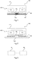
- FIG. 1 shows schematically a measuring device 100 according to the invention.
- the measuring device 100 has an electronics and sensor unit 120 , a battery 110 for supplying the electronics and sensor unit with energy, and a magnetic switch 130 .
- the measuring device has a housing 170 with a Housing wall 171, which completely encloses the electronics and sensor unit, the battery and the magnetic switch, so that dust, moisture and/or air and/or explosive gas cannot penetrate into the interior space enclosed by the housing.
- the battery cannot be replaced due to the closed housing.
- the magnetic switch can be designed as a reed switch. At least a part of the electronic and sensor unit is separated from the power supply by the battery by the reed switch as long as the magnet 140 keeps the magnetic switch 130 open and/or in a first switch state.
- an adhesive layer 160 for attaching the measuring device to a desired measuring location.
- the adhesive layer is covered by a protective film 150.
- a magnet 140 is connected to the protective film. If the protective film 150 is pulled off the adhesive layer 160 to attach the measuring device, the magnet 140 is removed from the magnetic switch 130 at the same time. As a result, the magnetic switch closes or switches to the second switch state, so that the electronic and sensor unit is supplied with energy from the battery and the device starts operating.
- FIG figure 2 shows schematically the measuring device 100 according to FIG figure 1 , after the protective film with the magnet has been removed from the adhesive layer 160 and the measuring device has been attached to the desired measuring location 180.
- the desired measurement location 180 is a container wall.
- the adhesive layer 160 ensures a material connection between the measuring point 180 and the housing 170 of the measuring device.
- the measuring device can, on the one hand, record measurement data of the container contents and, on the other hand, measurement data from the environment through the housing 170 and the container wall 180 .
- the container wall is preferably made of plastic (polyethylene, polyethylene).
- the measurement data are measurement data correlating with a fill level and/or a fill level of a medium in a container. These will measured using radar-based methods. However, other measurement data such as the temperature, for example the ambient temperature, and/or pressure, for example the air pressure, are also conceivable.
- figure 2 further illustrates that removing the magnet from the magnetic switch 130 causes the magnetic switch to close or transition to the second switch state such that the battery 110 powers the electronics and sensor assembly 120 .
- FIG figure 3 shows a flowchart to illustrate steps of a method for starting up the measuring device 100 according to an embodiment of the invention. Unless otherwise described, the measuring device 100 of FIG figure 3 the same features and elements as the measuring device 100 of FIG Figures 1 and 2 exhibit.
- a first step S1 the electronic and sensor unit 120 is supplied with energy from the battery 110 by removing the protective film 150 from the adhesive layer 160 .
- the measuring device 100 is attached and/or fixed at the desired measuring location 180 by means of the adhesive layer 160.
Landscapes
- Physics & Mathematics (AREA)
- Electromagnetism (AREA)
- Fluid Mechanics (AREA)
- General Physics & Mathematics (AREA)
- Thermal Sciences (AREA)
- Acoustics & Sound (AREA)
- Testing Or Calibration Of Command Recording Devices (AREA)
- Secondary Cells (AREA)
Claims (12)
- Dispositif de mesure (100) destiné à mesurer un niveau de remplissage et/ou un niveau d'interface dans un récipient par radar, pourvu :d'un boîtier (170) dans lequel est disposée une unité d'électronique et de capteur (120) destinée à acquérir une grandeur de mesure, d'une batterie (110) destinée à alimenter en énergie ladite unité d'électronique et de capteur, d'un interrupteur magnétique (130), d'un aimant (140) destiné à actionner ledit interrupteur magnétique, d'une couche adhésive (160) et d'une feuille de protection (150) destinée à recouvrir ladite couche adhésive ;ladite couche adhésive étant disposée à l'extérieur sur ledit boîtier et réalisée de manière à ce qu'elle permette de monter ledit dispositif de mesure à un lieu de mesure (180) souhaité ;ladite feuille de protection étant reliée audit aimant de manière à ce qu'un retrait de la feuille de protection de la couche adhésive ait pour conséquence que l'aiment soit retiré dudit boîtier ;ledit dispositif de mesure étant réalisé de manière à ce que le retrait dudit aimant dudit boîtier fait en sorte que ledit interrupteur magnétique passe d'un premier état d'interrupteur à un deuxième état d'interrupteur ;au moins une partie de l'unité d'électronique et de capteur n'étant, dans ledit premier état d'interrupteur, pas alimentée en énergie par ladite batterie ;cette partie de l'unité d'électronique et de capteur étant,dans ledit deuxième état d'interrupteur, alimentée en énergie par ladite batterie.
- Dispositif de mesure (100) selon la revendication 1,
le boîtier (170) renfermant l'intégralité de la batterie (110), de l'unité d'électronique et de capteur (120) et de l'interrupteur magnétique (130). - Dispositif de mesure (100) selon l'une des revendications 1 ou 2,
le boîtier (170) renfermant hermétiquement, notamment de manière étanche à la poussière, étanche à l'eau et/ou étanche à l'air, la batterie (110), l'unité d'électronique et de capteur (120) et l'interrupteur magnétique (130). - Dispositif de mesure (100) selon l'une des revendications précédentes,
le lieu de mesure (180) souhaité étant une paroi de récipient. - Dispositif de mesure (100) selon l'une des revendication précédentes,la couche adhésive (160) comportant un évidement destiné à l'aimant (140) ; et/ouledit aimant étant disposé dans un évidement entre le boîtier (170) et la feuille de protection (150).
- Dispositif de mesure (100) selon l'une des revendication précédentes,
le boîtier (170) étant réalisé de manière à ce qu'il permette d'acquérir la grandeur de mesure, au moyen de l'unité d'électronique et de capteur (120), à travers ledit boîtier, notamment à travers une paroi de boîtier dudit boîtier. - Dispositif de mesure (100) selon l'une des revendication précédentes,
le boîtier (170) comprenant au moins deux composants de boîtier ; et lesdits au moins deux composants de boîtier étant assemblés par soudage et/ou collage. - Dispositif de mesure (100) selon l'une des revendications 1 à 6,
le boîtier (170) étant réalisé d'une seule pièce par injection de matière plastique. - Dispositif de mesure (100) selon l'une des revendications précédentes,
l'intégralité du boîtier (170) étant fabriquée en une matière plastique, s'agissant notamment d'une matière thermoplastique. - Dispositif de mesure (100) selon l'une des revendication précédentes,
l'interrupteur magnétique (130) étant un interrupteur reed. - Dispositif de mesure (100) selon l'une des revendication précédentes, comportant en outre :
une unité de communication disposée dans ledit boîtier, ladite unité de communication étant conçue pour permettre une transmission sans fil de données de mesure à travers le boîtier (170). - Procédé de mise en œuvre du dispositif de mesure (100) selon la revendication 1, comportant les étapes consistant à :activer une alimentation en énergie de l'unité d'électronique et de capteur (120) par la batterie (110), en retirant la feuille de protection (150) de la couche adhésive (160) ; etmonter ledit dispositif de mesure sur le lieu de mesure (180) souhaité, au moyen de ladite couche adhésive.
Applications Claiming Priority (2)
| Application Number | Priority Date | Filing Date | Title |
|---|---|---|---|
| DE102018212965.7A DE102018212965A1 (de) | 2018-08-02 | 2018-08-02 | Batteriebetriebene messvorichtung |
| PCT/EP2019/067970 WO2020025251A1 (fr) | 2018-08-02 | 2019-07-04 | Dispositif de mesure fonctionnant sur batterie |
Publications (2)
| Publication Number | Publication Date |
|---|---|
| EP3721183A1 EP3721183A1 (fr) | 2020-10-14 |
| EP3721183B1 true EP3721183B1 (fr) | 2022-01-12 |
Family
ID=67514549
Family Applications (1)
| Application Number | Title | Priority Date | Filing Date |
|---|---|---|---|
| EP19748690.5A Active EP3721183B1 (fr) | 2018-08-02 | 2019-07-04 | Dispositif de mesure fonctionnant sur batterie |
Country Status (6)
| Country | Link |
|---|---|
| US (1) | US12392650B2 (fr) |
| EP (1) | EP3721183B1 (fr) |
| KR (1) | KR102603004B1 (fr) |
| CN (1) | CN112513588A (fr) |
| DE (1) | DE102018212965A1 (fr) |
| WO (1) | WO2020025251A1 (fr) |
Families Citing this family (2)
| Publication number | Priority date | Publication date | Assignee | Title |
|---|---|---|---|---|
| EP4303491A1 (fr) | 2022-07-08 | 2024-01-10 | EWR Consult - Ingeneurbüro für Umwelttechnik e.U. | Procédé de détermination de la charge totale, biogénique et fossile de carbone et de co2, ainsi que du débit volumique des gaz d'échappement lors de la combustion des déchets et des combustibles résiduaires |
| DE102022119150A1 (de) * | 2022-07-29 | 2024-02-01 | Xeotech Gmbh | Vorrichtung sowie Verfahren zum Betreiben einer Vorrichtung |
Citations (3)
| Publication number | Priority date | Publication date | Assignee | Title |
|---|---|---|---|---|
| US8970395B2 (en) * | 2012-06-29 | 2015-03-03 | Rosemount Tank Radar Ab | Battery-powered level gauge system adapted for wireless communication |
| US20150373487A1 (en) * | 2014-06-23 | 2015-12-24 | Hirschmann Car Communication Inc. | Long life container tracking device and method for detecting tampering with the tracking device |
| WO2018057911A1 (fr) * | 2016-09-23 | 2018-03-29 | Mc10, Inc. | Procédés et systèmes pour relier une source d'alimentation à des dispositifs mobiles |
Family Cites Families (18)
| Publication number | Priority date | Publication date | Assignee | Title |
|---|---|---|---|---|
| DE19904303A1 (de) * | 1999-01-28 | 2000-08-24 | Bosch Gmbh Robert | Gehäuse für ein elektronisches Gerät in der Mikrowellentechnik |
| WO2003085365A1 (fr) * | 2002-04-10 | 2003-10-16 | Vega Grieshaber Kg | Appareil de mesure de niveau renfermant de l'equipement electronique et une antenne dans un boitier |
| US8886272B2 (en) | 2004-07-13 | 2014-11-11 | Dexcom, Inc. | Analyte sensor |
| US20070129769A1 (en) * | 2005-12-02 | 2007-06-07 | Medtronic, Inc. | Wearable ambulatory data recorder |
| GB0815897D0 (en) * | 2008-09-01 | 2008-10-08 | Benmore Ventures Ltd | Container illumination device |
| US8928190B2 (en) * | 2009-12-31 | 2015-01-06 | Ultralife Corporation | System and method for activating an isolated device |
| DE202011004772U1 (de) * | 2011-04-01 | 2011-06-01 | Sensorentechnologie Gettorf GmbH, 24214 | Füllstandssensor |
| US10018487B2 (en) | 2011-06-15 | 2018-07-10 | Honeywell International Inc. | Methods and systems for activating sealed sensors in the field |
| EP4736749A2 (fr) | 2013-04-30 | 2026-05-06 | Abbott Diabetes Care Inc. | Systèmes, dispositifs et procédés d'activation de dispositif électrique éco-énergétique |
| DE102014006276A1 (de) * | 2014-05-02 | 2015-11-05 | Meas Deutschland Gmbh | Messvorrichtung sowie Verfahren zum Messen des Pegels einer Flüssigkeit in einem Behälter |
| WO2015181770A2 (fr) | 2014-05-30 | 2015-12-03 | Eltek S.P.A. | Capteur pour détecter le niveau d'un milieu |
| US20150371511A1 (en) * | 2014-06-23 | 2015-12-24 | Hirschmann Car Communication Inc. | Long life container tracking device and method for detecting movement of container structure |
| MX380917B (es) * | 2015-02-18 | 2025-03-12 | Ti Group Automotive Systems Llc | Transmisor de nivel. |
| CN104931940B (zh) * | 2015-06-11 | 2017-03-01 | 西安理工大学 | 一种基于锁相跟踪环路的穿墙探测墙体抑制方法 |
| CN205543216U (zh) * | 2016-01-29 | 2016-08-31 | 桂林电子科技大学 | 一种用于隐藏目标探测的超宽带双极化天线 |
| ITUA20161342A1 (it) * | 2016-03-04 | 2017-09-04 | Eltek Spa | Dispositivo sensore per contenitori di sostanze liquide |
| ITUA20163239A1 (it) * | 2016-04-18 | 2017-10-18 | Eltek Spa | Dispositivo per la rilevazione del livello di un mezzo |
| CN107642279A (zh) * | 2017-09-01 | 2018-01-30 | 深圳圣保路皮具有限公司 | 拉片内置磁铁式磁感应五金报警锁 |
-
2018
- 2018-08-02 DE DE102018212965.7A patent/DE102018212965A1/de active Pending
-
2019
- 2019-07-04 US US17/263,665 patent/US12392650B2/en active Active
- 2019-07-04 WO PCT/EP2019/067970 patent/WO2020025251A1/fr not_active Ceased
- 2019-07-04 EP EP19748690.5A patent/EP3721183B1/fr active Active
- 2019-07-04 CN CN201980050750.0A patent/CN112513588A/zh active Pending
- 2019-07-04 KR KR1020217004388A patent/KR102603004B1/ko active Active
Patent Citations (3)
| Publication number | Priority date | Publication date | Assignee | Title |
|---|---|---|---|---|
| US8970395B2 (en) * | 2012-06-29 | 2015-03-03 | Rosemount Tank Radar Ab | Battery-powered level gauge system adapted for wireless communication |
| US20150373487A1 (en) * | 2014-06-23 | 2015-12-24 | Hirschmann Car Communication Inc. | Long life container tracking device and method for detecting tampering with the tracking device |
| WO2018057911A1 (fr) * | 2016-09-23 | 2018-03-29 | Mc10, Inc. | Procédés et systèmes pour relier une source d'alimentation à des dispositifs mobiles |
Also Published As
| Publication number | Publication date |
|---|---|
| KR102603004B1 (ko) | 2023-11-16 |
| KR20210034022A (ko) | 2021-03-29 |
| CN112513588A (zh) | 2021-03-16 |
| DE102018212965A1 (de) | 2020-02-06 |
| WO2020025251A1 (fr) | 2020-02-06 |
| US12392650B2 (en) | 2025-08-19 |
| US20210215525A1 (en) | 2021-07-15 |
| EP3721183A1 (fr) | 2020-10-14 |
Similar Documents
| Publication | Publication Date | Title |
|---|---|---|
| EP3605032B1 (fr) | Capteur radar destiné à la mesure de niveau de remplissage ou de niveau limite | |
| EP3605031B1 (fr) | Capteur radar destiné à la mesure de niveau de remplissage ou de niveau limite | |
| EP3721183B1 (fr) | Dispositif de mesure fonctionnant sur batterie | |
| EP3913819A1 (fr) | Procédé de calibrage d'un système de mesure utilisant la réflectométrie de domaine temporel | |
| EP3973484B1 (fr) | Suivi de produits | |
| US20150082881A1 (en) | Apparatus for determining and/or monitoring at least one process variable of a medium | |
| WO2007085518A2 (fr) | Dispositif permettant de déterminer et de surveiller le niveau d'un milieu dans un contenant | |
| DE102013112025A1 (de) | Vorrichtung zur Bestimmung oder Überwachung des Füllstands eines Mediums in einem Behälter | |
| US12061107B2 (en) | Calibration method for a TDR measurement | |
| US6798184B2 (en) | Integrated sensor device and measuring system using the same | |
| WO2012062574A1 (fr) | Cellule de batterie, procédé de fabrication d'une cellule de batterie et utilisation d'une cellule de batterie | |
| US20260056155A1 (en) | Capacitance-based humidity and gas sensing rfid tags | |
| DE102012215883A1 (de) | Energiespeicher mit Dichtigkeitsüberwachung | |
| WO2021083571A1 (fr) | Système de détection, utilisation d'un système de détection, dispositif et procédé de mesure d'un niveau de remplissage | |
| DE102019205393B4 (de) | Sensor zur Füllstand- oder Grenzstandmessung | |
| KR20120125241A (ko) | 전자 유체 표시기 및 표시 방법 | |
| WO2023099268A1 (fr) | Jauge de niveau actionnée par radar | |
| RU2772745C1 (ru) | Измерительное устройство с батарейным питанием | |
| US20240035873A1 (en) | High-frequency module for a level meter | |
| EP4040117A1 (fr) | Appareil de mesure pourvu de dispositif de fixation souple | |
| WO1993008036A1 (fr) | Procede, dispositif et capuchon de valve de mesure et d'indication de la pression de gonflage d'un pneu | |
| EP4478046A2 (fr) | Compteur de gaz avec détection automatique de configuration et procédé de configuration | |
| DE102009055406B3 (de) | Vorrichtung und Verfahren zur Aufnahme von Messdaten einer Messgröße | |
| CN202049393U (zh) | 一种智能射频导纳物位控制器 | |
| DE4133991A1 (de) | Vorrichtung zum messen und anzeigen des druckes in einem mit einem ventil ausgeruesteten luftreifen |
Legal Events
| Date | Code | Title | Description |
|---|---|---|---|
| STAA | Information on the status of an ep patent application or granted ep patent |
Free format text: STATUS: UNKNOWN |
|
| STAA | Information on the status of an ep patent application or granted ep patent |
Free format text: STATUS: THE INTERNATIONAL PUBLICATION HAS BEEN MADE |
|
| PUAI | Public reference made under article 153(3) epc to a published international application that has entered the european phase |
Free format text: ORIGINAL CODE: 0009012 |
|
| STAA | Information on the status of an ep patent application or granted ep patent |
Free format text: STATUS: REQUEST FOR EXAMINATION WAS MADE |
|
| 17P | Request for examination filed |
Effective date: 20200706 |
|
| AK | Designated contracting states |
Kind code of ref document: A1 Designated state(s): AL AT BE BG CH CY CZ DE DK EE ES FI FR GB GR HR HU IE IS IT LI LT LU LV MC MK MT NL NO PL PT RO RS SE SI SK SM TR |
|
| AX | Request for extension of the european patent |
Extension state: BA ME |
|
| STAA | Information on the status of an ep patent application or granted ep patent |
Free format text: STATUS: EXAMINATION IS IN PROGRESS |
|
| 17Q | First examination report despatched |
Effective date: 20201218 |
|
| GRAP | Despatch of communication of intention to grant a patent |
Free format text: ORIGINAL CODE: EPIDOSNIGR1 |
|
| STAA | Information on the status of an ep patent application or granted ep patent |
Free format text: STATUS: GRANT OF PATENT IS INTENDED |
|
| DAV | Request for validation of the european patent (deleted) | ||
| DAX | Request for extension of the european patent (deleted) | ||
| INTG | Intention to grant announced |
Effective date: 20210726 |
|
| GRAS | Grant fee paid |
Free format text: ORIGINAL CODE: EPIDOSNIGR3 |
|
| GRAA | (expected) grant |
Free format text: ORIGINAL CODE: 0009210 |
|
| STAA | Information on the status of an ep patent application or granted ep patent |
Free format text: STATUS: THE PATENT HAS BEEN GRANTED |
|
| AK | Designated contracting states |
Kind code of ref document: B1 Designated state(s): AL AT BE BG CH CY CZ DE DK EE ES FI FR GB GR HR HU IE IS IT LI LT LU LV MC MK MT NL NO PL PT RO RS SE SI SK SM TR |
|
| REG | Reference to a national code |
Ref country code: GB Ref legal event code: FG4D Free format text: NOT ENGLISH |
|
| REG | Reference to a national code |
Ref country code: CH Ref legal event code: EP |
|
| REG | Reference to a national code |
Ref country code: DE Ref legal event code: R096 Ref document number: 502019003234 Country of ref document: DE |
|
| REG | Reference to a national code |
Ref country code: IE Ref legal event code: FG4D Free format text: LANGUAGE OF EP DOCUMENT: GERMAN |
|
| REG | Reference to a national code |
Ref country code: AT Ref legal event code: REF Ref document number: 1462683 Country of ref document: AT Kind code of ref document: T Effective date: 20220215 |
|
| REG | Reference to a national code |
Ref country code: LT Ref legal event code: MG9D |
|
| REG | Reference to a national code |
Ref country code: NL Ref legal event code: MP Effective date: 20220112 |
|
| PG25 | Lapsed in a contracting state [announced via postgrant information from national office to epo] |
Ref country code: NL Free format text: LAPSE BECAUSE OF FAILURE TO SUBMIT A TRANSLATION OF THE DESCRIPTION OR TO PAY THE FEE WITHIN THE PRESCRIBED TIME-LIMIT Effective date: 20220112 |
|
| PG25 | Lapsed in a contracting state [announced via postgrant information from national office to epo] |
Ref country code: SE Free format text: LAPSE BECAUSE OF FAILURE TO SUBMIT A TRANSLATION OF THE DESCRIPTION OR TO PAY THE FEE WITHIN THE PRESCRIBED TIME-LIMIT Effective date: 20220112 Ref country code: RS Free format text: LAPSE BECAUSE OF FAILURE TO SUBMIT A TRANSLATION OF THE DESCRIPTION OR TO PAY THE FEE WITHIN THE PRESCRIBED TIME-LIMIT Effective date: 20220112 Ref country code: PT Free format text: LAPSE BECAUSE OF FAILURE TO SUBMIT A TRANSLATION OF THE DESCRIPTION OR TO PAY THE FEE WITHIN THE PRESCRIBED TIME-LIMIT Effective date: 20220512 Ref country code: NO Free format text: LAPSE BECAUSE OF FAILURE TO SUBMIT A TRANSLATION OF THE DESCRIPTION OR TO PAY THE FEE WITHIN THE PRESCRIBED TIME-LIMIT Effective date: 20220412 Ref country code: LT Free format text: LAPSE BECAUSE OF FAILURE TO SUBMIT A TRANSLATION OF THE DESCRIPTION OR TO PAY THE FEE WITHIN THE PRESCRIBED TIME-LIMIT Effective date: 20220112 Ref country code: HR Free format text: LAPSE BECAUSE OF FAILURE TO SUBMIT A TRANSLATION OF THE DESCRIPTION OR TO PAY THE FEE WITHIN THE PRESCRIBED TIME-LIMIT Effective date: 20220112 Ref country code: ES Free format text: LAPSE BECAUSE OF FAILURE TO SUBMIT A TRANSLATION OF THE DESCRIPTION OR TO PAY THE FEE WITHIN THE PRESCRIBED TIME-LIMIT Effective date: 20220112 Ref country code: BG Free format text: LAPSE BECAUSE OF FAILURE TO SUBMIT A TRANSLATION OF THE DESCRIPTION OR TO PAY THE FEE WITHIN THE PRESCRIBED TIME-LIMIT Effective date: 20220412 |
|
| PG25 | Lapsed in a contracting state [announced via postgrant information from national office to epo] |
Ref country code: PL Free format text: LAPSE BECAUSE OF FAILURE TO SUBMIT A TRANSLATION OF THE DESCRIPTION OR TO PAY THE FEE WITHIN THE PRESCRIBED TIME-LIMIT Effective date: 20220112 Ref country code: LV Free format text: LAPSE BECAUSE OF FAILURE TO SUBMIT A TRANSLATION OF THE DESCRIPTION OR TO PAY THE FEE WITHIN THE PRESCRIBED TIME-LIMIT Effective date: 20220112 Ref country code: GR Free format text: LAPSE BECAUSE OF FAILURE TO SUBMIT A TRANSLATION OF THE DESCRIPTION OR TO PAY THE FEE WITHIN THE PRESCRIBED TIME-LIMIT Effective date: 20220413 Ref country code: FI Free format text: LAPSE BECAUSE OF FAILURE TO SUBMIT A TRANSLATION OF THE DESCRIPTION OR TO PAY THE FEE WITHIN THE PRESCRIBED TIME-LIMIT Effective date: 20220112 |
|
| PG25 | Lapsed in a contracting state [announced via postgrant information from national office to epo] |
Ref country code: IS Free format text: LAPSE BECAUSE OF FAILURE TO SUBMIT A TRANSLATION OF THE DESCRIPTION OR TO PAY THE FEE WITHIN THE PRESCRIBED TIME-LIMIT Effective date: 20220512 |
|
| REG | Reference to a national code |
Ref country code: DE Ref legal event code: R097 Ref document number: 502019003234 Country of ref document: DE |
|
| PG25 | Lapsed in a contracting state [announced via postgrant information from national office to epo] |
Ref country code: SM Free format text: LAPSE BECAUSE OF FAILURE TO SUBMIT A TRANSLATION OF THE DESCRIPTION OR TO PAY THE FEE WITHIN THE PRESCRIBED TIME-LIMIT Effective date: 20220112 Ref country code: SK Free format text: LAPSE BECAUSE OF FAILURE TO SUBMIT A TRANSLATION OF THE DESCRIPTION OR TO PAY THE FEE WITHIN THE PRESCRIBED TIME-LIMIT Effective date: 20220112 Ref country code: RO Free format text: LAPSE BECAUSE OF FAILURE TO SUBMIT A TRANSLATION OF THE DESCRIPTION OR TO PAY THE FEE WITHIN THE PRESCRIBED TIME-LIMIT Effective date: 20220112 Ref country code: EE Free format text: LAPSE BECAUSE OF FAILURE TO SUBMIT A TRANSLATION OF THE DESCRIPTION OR TO PAY THE FEE WITHIN THE PRESCRIBED TIME-LIMIT Effective date: 20220112 Ref country code: DK Free format text: LAPSE BECAUSE OF FAILURE TO SUBMIT A TRANSLATION OF THE DESCRIPTION OR TO PAY THE FEE WITHIN THE PRESCRIBED TIME-LIMIT Effective date: 20220112 Ref country code: CZ Free format text: LAPSE BECAUSE OF FAILURE TO SUBMIT A TRANSLATION OF THE DESCRIPTION OR TO PAY THE FEE WITHIN THE PRESCRIBED TIME-LIMIT Effective date: 20220112 |
|
| PLBE | No opposition filed within time limit |
Free format text: ORIGINAL CODE: 0009261 |
|
| STAA | Information on the status of an ep patent application or granted ep patent |
Free format text: STATUS: NO OPPOSITION FILED WITHIN TIME LIMIT |
|
| PG25 | Lapsed in a contracting state [announced via postgrant information from national office to epo] |
Ref country code: AL Free format text: LAPSE BECAUSE OF FAILURE TO SUBMIT A TRANSLATION OF THE DESCRIPTION OR TO PAY THE FEE WITHIN THE PRESCRIBED TIME-LIMIT Effective date: 20220112 |
|
| 26N | No opposition filed |
Effective date: 20221013 |
|
| PG25 | Lapsed in a contracting state [announced via postgrant information from national office to epo] |
Ref country code: SI Free format text: LAPSE BECAUSE OF FAILURE TO SUBMIT A TRANSLATION OF THE DESCRIPTION OR TO PAY THE FEE WITHIN THE PRESCRIBED TIME-LIMIT Effective date: 20220112 Ref country code: MC Free format text: LAPSE BECAUSE OF FAILURE TO SUBMIT A TRANSLATION OF THE DESCRIPTION OR TO PAY THE FEE WITHIN THE PRESCRIBED TIME-LIMIT Effective date: 20220112 |
|
| REG | Reference to a national code |
Ref country code: CH Ref legal event code: PL |
|
| REG | Reference to a national code |
Ref country code: BE Ref legal event code: MM Effective date: 20220731 |
|
| PG25 | Lapsed in a contracting state [announced via postgrant information from national office to epo] |
Ref country code: LU Free format text: LAPSE BECAUSE OF NON-PAYMENT OF DUE FEES Effective date: 20220704 Ref country code: LI Free format text: LAPSE BECAUSE OF NON-PAYMENT OF DUE FEES Effective date: 20220731 Ref country code: CH Free format text: LAPSE BECAUSE OF NON-PAYMENT OF DUE FEES Effective date: 20220731 |
|
| PG25 | Lapsed in a contracting state [announced via postgrant information from national office to epo] |
Ref country code: BE Free format text: LAPSE BECAUSE OF NON-PAYMENT OF DUE FEES Effective date: 20220731 |
|
| P01 | Opt-out of the competence of the unified patent court (upc) registered |
Effective date: 20230508 |
|
| PG25 | Lapsed in a contracting state [announced via postgrant information from national office to epo] |
Ref country code: IT Free format text: LAPSE BECAUSE OF FAILURE TO SUBMIT A TRANSLATION OF THE DESCRIPTION OR TO PAY THE FEE WITHIN THE PRESCRIBED TIME-LIMIT Effective date: 20220112 Ref country code: IE Free format text: LAPSE BECAUSE OF NON-PAYMENT OF DUE FEES Effective date: 20220704 |
|
| PG25 | Lapsed in a contracting state [announced via postgrant information from national office to epo] |
Ref country code: MK Free format text: LAPSE BECAUSE OF FAILURE TO SUBMIT A TRANSLATION OF THE DESCRIPTION OR TO PAY THE FEE WITHIN THE PRESCRIBED TIME-LIMIT Effective date: 20220112 Ref country code: CY Free format text: LAPSE BECAUSE OF FAILURE TO SUBMIT A TRANSLATION OF THE DESCRIPTION OR TO PAY THE FEE WITHIN THE PRESCRIBED TIME-LIMIT Effective date: 20220112 |
|
| PG25 | Lapsed in a contracting state [announced via postgrant information from national office to epo] |
Ref country code: HU Free format text: LAPSE BECAUSE OF FAILURE TO SUBMIT A TRANSLATION OF THE DESCRIPTION OR TO PAY THE FEE WITHIN THE PRESCRIBED TIME-LIMIT; INVALID AB INITIO Effective date: 20190704 |
|
| PG25 | Lapsed in a contracting state [announced via postgrant information from national office to epo] |
Ref country code: MT Free format text: LAPSE BECAUSE OF FAILURE TO SUBMIT A TRANSLATION OF THE DESCRIPTION OR TO PAY THE FEE WITHIN THE PRESCRIBED TIME-LIMIT Effective date: 20220112 |
|
| REG | Reference to a national code |
Ref country code: AT Ref legal event code: MM01 Ref document number: 1462683 Country of ref document: AT Kind code of ref document: T Effective date: 20240704 |
|
| PGFP | Annual fee paid to national office [announced via postgrant information from national office to epo] |
Ref country code: DE Payment date: 20250722 Year of fee payment: 7 |
|
| PGFP | Annual fee paid to national office [announced via postgrant information from national office to epo] |
Ref country code: GB Payment date: 20250724 Year of fee payment: 7 |
|
| PG25 | Lapsed in a contracting state [announced via postgrant information from national office to epo] |
Ref country code: AT Free format text: LAPSE BECAUSE OF NON-PAYMENT OF DUE FEES Effective date: 20240704 |
|
| PGFP | Annual fee paid to national office [announced via postgrant information from national office to epo] |
Ref country code: FR Payment date: 20250723 Year of fee payment: 7 |
|
| PG25 | Lapsed in a contracting state [announced via postgrant information from national office to epo] |
Ref country code: TR Free format text: LAPSE BECAUSE OF FAILURE TO SUBMIT A TRANSLATION OF THE DESCRIPTION OR TO PAY THE FEE WITHIN THE PRESCRIBED TIME-LIMIT Effective date: 20220112 |
|
| PGFP | Annual fee paid to national office [announced via postgrant information from national office to epo] |
Ref country code: AT Payment date: 20260410 Year of fee payment: 5 |