EP3722068B1 - Broche d'éjection pourvue d'une sécurité anti-rotation - Google Patents
Broche d'éjection pourvue d'une sécurité anti-rotation Download PDFInfo
- Publication number
- EP3722068B1 EP3722068B1 EP20169351.2A EP20169351A EP3722068B1 EP 3722068 B1 EP3722068 B1 EP 3722068B1 EP 20169351 A EP20169351 A EP 20169351A EP 3722068 B1 EP3722068 B1 EP 3722068B1
- Authority
- EP
- European Patent Office
- Prior art keywords
- head
- ejector pin
- support plate
- ejector
- shaft
- Prior art date
- Legal status (The legal status is an assumption and is not a legal conclusion. Google has not performed a legal analysis and makes no representation as to the accuracy of the status listed.)
- Active
Links
Images

Classifications
-
- B—PERFORMING OPERATIONS; TRANSPORTING
- B29—WORKING OF PLASTICS; WORKING OF SUBSTANCES IN A PLASTIC STATE IN GENERAL
- B29C—SHAPING OR JOINING OF PLASTICS; SHAPING OF MATERIAL IN A PLASTIC STATE, NOT OTHERWISE PROVIDED FOR; AFTER-TREATMENT OF THE SHAPED PRODUCTS, e.g. REPAIRING
- B29C45/00—Injection moulding, i.e. forcing the required volume of moulding material through a nozzle into a closed mould; Apparatus therefor
- B29C45/17—Component parts, details or accessories; Auxiliary operations
- B29C45/40—Removing or ejecting moulded articles
- B29C45/4005—Ejector constructions; Ejector operating mechanisms
- B29C45/401—Ejector pin constructions or mountings
-
- B—PERFORMING OPERATIONS; TRANSPORTING
- B22—CASTING; POWDER METALLURGY
- B22D—CASTING OF METALS; CASTING OF OTHER SUBSTANCES BY THE SAME PROCESSES OR DEVICES
- B22D17/00—Pressure die casting or injection die casting, i.e. casting in which the metal is forced into a mould under high pressure
- B22D17/20—Accessories: Details
- B22D17/22—Dies; Die plates; Die supports; Cooling equipment for dies; Accessories for loosening and ejecting castings from dies
- B22D17/2236—Equipment for loosening or ejecting castings from dies
Definitions
- the present invention relates generally to casting tools, and for example to an ejector pin for ejecting molded parts and to a support plate-ejector pin arrangement with one or more such ejector pins.
- the general task is to remove the solidified molded part from the mold at the end of the casting process. This is often done using one or more ejector pins, which are arranged on a movable support plate and each extend into the mold through a hole; the ejector pins are usually flush with the inner wall of the mold when the ejector is not activated.
- Ejection of a cast part occurs after opening the casting tool by moving the support plate with the ejector pin(s) towards the mold, causing the ejector pin(s) to penetrate the mold and thus eject the molded part.
- Ejector pins are known as case ejectors (with internal clearance) and as solid pins (without internal clearance) (see e.g. the mentioned DE 43 16 029 C1 as well as DE 33 45 366 A1 ).
- the shape of the front face of the ejector pin corresponds to the shape of the mold at the point where the ejector pin is located. If, for example, the wall of the mold is inclined, the ejector pin will have a corresponding inclination on the front face (relative to its longitudinal axis). If, for example, the mold has a step at the corresponding point, the ejector pin will also have a corresponding step on the front face. In such cases, the ejector pin must be installed in a defined position with respect to rotation about its own axis and be secured against twisting about its own axis.
- the invention relates to an ejector pin for ejecting molded parts from casting tools according to claim 1.
- the bevel can be formed by milling or other suitable manufacturing processes. It is preferably formed by forming (e.g. upsetting).
- the bevel is provided in sections on the peripheral surface of the head. However, it is formed all the way around the head.
- the bevel has an angle to the shaft longitudinal axis in a range of 3° to 10°.
- the head peripheral surface comprises, in particular in an upper partial section of the head peripheral surface, a contact surface for contact with the complementary recess in the support plate.
- a center offset can be generated by varying the distance between the opposite straight circumferential sections and the shaft center. This in turn means that different radii and surface lengths can be formed, which enable the installation position of the ejector pin to be easily distinguished visually.
- the different radii due to the center offset increase the optical recognition and even enable haptic recognition for a user.
- a two-sided anti-twisting device which has a higher accuracy than a one-sided anti-twisting device.
- the compression of the head also enables a space-saving design of the head shape, so that narrow distances can be provided between the ejector pins in a support plate.
- a further aspect relates to a support plate-ejector pin arrangement with a support plate with one or more bores with receptacles into which ejector pins of the above-mentioned type are inserted.
- the receptacles are complementary to the ejector pin head shape and receive the heads.
- the shafts pass through the bores.
- the bores have a diameter so much larger than the shafts that the position of the ejector pin(s) in the support plate in the transverse direction to the opposite straight peripheral sections is defined by these peripheral sections in cooperation with complementary peripheral sections of the receptacles, but not by the bores.
- Fig. 1 shows a side view of an injection mold in which embodiments of the ejector pins according to the invention are installed. Before a detailed description the Fig. 1 First, various explanations of the embodiments follow.
- the described embodiments show an ejector pin with a shaft and a head formed by forming (e.g. upsetting).
- the head can also be designed by milling or other suitable methods.
- the head has two opposite, straight peripheral sections, viewed in the longitudinal direction of the shaft.
- the opposite, straight peripheral sections serve to prevent rotation when the ejector pin is mounted in a complementary support plate.
- the support plate has a complementary recess for receiving the head, which - depending on the shape of the head - has at least two opposite, straight peripheral sections.
- the opposite, straight peripheral sections run parallel to one another. In some of these embodiments, they are at the same distance from the shaft center, i.e. are symmetrical to it. In other of these embodiments, however, they run at different distances from the shaft center, i.e. are asymmetrical to it.
- the opposing straight circumferential sections do not run parallel to one another, but rather at a small angle to one another, for example.
- one or more of the opposing straight circumferential sections are composed of subsections at an angle.
- the property "straight" in these cases therefore refers to the fact that they are composed of straight subsections.
- the head can essentially have the shape of a hexagon, in which two subsections adjacent to one another at 60 degrees together form a "straight circumferential section composed of subsections at an angle", and two such composite sections are opposite one another (however, in the case of such a hexagon, a "symmetry-cancelling measure for eliminating the 60-degree symmetry is also required). be added, see below).
- the head is also shaped in such a way that the ejector pin can only be mounted in the complementary support plate in one clear installation position.
- the head shape has (only) 360-degree symmetry, i.e. it only covers itself after a rotation of 360 degrees at the earliest (in contrast, for example, a head with symmetrically connected and symmetrically arranged straight peripheral sections has 180-degree symmetry, and a hexagon head (which covers itself after a rotation of 60 degrees) has 60-degree symmetry).
- the head therefore has a shape that excludes such an installation, e.g. only rotated by 180 degrees or 60 degrees.
- another straight circumferential section that runs at right angles to the opposite straight circumferential sections and a curved circumferential section opposite this are provided.
- Some of the embodiments are produced, for example, by first The head was formed in a rough form by forming the shaft material (e.g. by upsetting), and then the opposite straight peripheral sections were worked out by removing material, e.g. by milling or grinding.
- the upsetting can be done centrally to the longitudinal axis of the shaft.
- the head is already produced with the straight peripheral sections by uniforms (e.g. upsetting), for example by arranging the end of the shaft to be formed in a suitable shape during the forming process.
- the flat surfaces corresponding to the straight peripheral sections can be produced with significantly greater accuracy than, for example, the DE 33 45 366 A1 proposed eccentric heads.
- the opposite straight peripheral sections of the described embodiments are manufactured with tolerances of less than or equal to 0.02 mm relative to one another.
- tolerances of the eccentric heads mentioned are usually only in the order of magnitude of 0.2 mm.
- an increase in accuracy of approximately one order of magnitude ie a factor of 10
- the accuracy in defining the angular position of the ejector pin is increased even further, since the surfaces mentioned are generally supported against rotation in a complementary receptacle with a larger lever arm than an eccentric head of the corresponding size.
- the embodiments also describe a support plate-ejector pin arrangement, i.e. a support plate with one or more built-in ejector pins of the type mentioned.
- the support plate has one or more receptacles that are complementary to the ejector pin head shape, i.e. also two opposite, straight peripheral sections.
- the receptacles can be produced, for example, by milling.
- the DE 33 45 366 A1 known eccentric ejector pins tend to become distorted in the support plate. The probable reason for this was found to be that when the head is manufactured by forming (e.g. upsetting), the shaft is also compressed and that this becomes somewhat thicker (typically by 0.02 to 0.05 mm thicker, although this can vary considerably from case to case). Since the eccentric head of the DE 33 45 366 A1 in a complementary support plate recess does not act as a locking element on its own, but only in conjunction with the shaft, which is supported in the shaft bore by the support plate, had to be taken into account in the DE 33 45 366 A1 In practice, the diameter of the shaft bore should be chosen without air, i.e. equal to the nominal shaft diameter. Due to the aforementioned (varying) thickening of the shaft, this led to a more or less pronounced distortion of the ejector pin in the support plate.
- the ejector pin is "floating" in the shaft bore; that is, the diameter of the shaft bore is chosen to be large enough that the position of the ejector pin in the support plate in the transverse direction to the opposite straight peripheral sections is defined by these peripheral sections in cooperation with the complementary peripheral sections of the receptacle, but not by the shaft bore.
- the shaft bore has a diameter that is 0.1 mm larger than the shaft, in other embodiments it is even 0.2 mm larger.
- the tolerance of the pin angular position depends on a number of factors (which are difficult to control), such as head diameter, head position, thickening of the shaft, incorporation of the shaft bore in the support plate, incorporation of the head shape in the support plate), this tolerance in the embodiments of the invention depends only on the tolerance of the straight peripheral sections relative to one another and their incorporation in the support plate. It has also been shown that the tendency to warp observed with eccentric heads is excluded with the embodiments of the ejector pin. In addition, the straight peripheral sections allow the angular position of an ejector pin to be defined precisely, unlike with the known eccentric heads.
- FIG. 1 shows a side sectional view of an exemplary casting mold 1 with ejection device in a known construction (known e.g. from the above-mentioned DE 33 45 366 A1 ).
- the casting mold 1 is essentially made up of an upper and a lower mold half 2, 3 (designations such as “top” and “bottom” refer to the Fig. 1 Orientation of the casting mold 1 shown). Between the two mold halves 2, 3 there is a mold cavity 4.
- the lower mold half 3 is equipped with the ejection device. This is made up of several (here: two) ejector pins 5 according to the embodiments of the invention described in more detail below, which are accommodated in bores in the lower mold half 3 so that they can be moved longitudinally.
- the ejector pins 5 have a cylindrical (e.g. circular cylindrical) shaft 6 and a flange-like protruding head 7 formed on it. They are installed with their heads 7 in a rotationally secure manner in a support plate 8 which can be moved in the longitudinal direction of the shafts 6 by an ejection drive in the direction of the mold cavity 4. After opening the mold (ie removing the upper mold half 2), the molding produced in the mold cavity 4 is ejected by moving the support plate 8 in the direction mentioned, whereby it moves the ejector pins 5 upwards; these accordingly press the molding upwards and thus push it away from the lower mold half 3.
- a cylindrical e.g. circular cylindrical
- flange-like protruding head 7 formed on it. They are installed with their heads 7 in a rotationally secure manner in a support plate 8 which can be moved in the longitudinal direction of the shafts 6 by an ejection drive in the direction of the mold cavity 4.
- the front faces 9 of the ejector pins 5 in the non-ejection position each form part of the wall of the lower mold half 3.
- this wall runs inclined to the longitudinal axis of the ejector pins 5; consequently, the front faces 9 are also designed with a corresponding inclination relative to the ejector pin longitudinal axis.
- the shape of the heads 7 of the ejector pins 5 described below and their accommodation in complementary recesses 10 of the support plate 8 ensure that the ejector pins 5 cannot twist, and thus their inclined front faces 9 always remain in the correct position and thus always present the correct inclination.
- the front area of the ejector pins 5 can have any shape predetermined by the desired shape of the mold cavity 4.
- An anti-twisting device is always necessary if this shape is not rotationally symmetrical with respect to the longitudinal axis of the ejector pins 5.
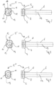
- Fig. 2 shows a first embodiment of the ejector pin 5, the head 7 of which has two opposite straight peripheral sections 11, which run parallel to one another at the same distance from the longitudinal axis 13 of the ejector pin 5.
- the head 7 also has another straight peripheral section 19 on one side, but a curved peripheral section 12 on the opposite side.
- the straight sections 11, 19 do not touch one another; rather, there is a radius 14 between them.
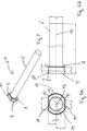
- the head 7 additionally has a circumferential slope S. This slope is also present in the embodiments according to Figs. 3 and used and designed accordingly.
- the head peripheral surface K comprises, in particular in an upper section of the head peripheral surface, a contact surface AF for contact with the complementary recess in the support plate.
- the head 7 comprises on its underside a support surface A for contact with the support plate 8.
- the bevel S can have an angle to the longitudinal axis in a range of 1° to 25°. This range is preferably in a range between 1° and 15°, particularly preferably the angle W is 5°. This serves for pre-centering for simple and quick assembly of the ejector pin 5′′′ in the support plate.
- FIG. 4 Another example of an ejector pin (here marked 5") is shown in Fig. 4
- the head 7 has two opposite straight peripheral sections 11, 11', one of which is formed by two subsections 11' joined at an angle. This already ensures a clear definition of the installation position (360-degree symmetry), so that the straight peripheral sections 11, 11' are connected to equally curved peripheral sections 12 on both sides.
- the head 7 is produced by upsetting and then working out the straight and curved sections 11, 11', 12, 19 and the radii 14 by milling or grinding.
- the opposite straight sections 11, 11' are in the embodiments of the Fig. 2 to Fig. 4 and 7 to 8b with a tolerance of approximately 0.02 mm relative to one another. Since the other circumferential sections 12, 19 do not serve to define the angular position of the ejector pin 5, 5', 5", 5′′′, they are manufactured with larger tolerances in some embodiments.
- the head 7 is already formed together with the sections 11, 11', 12, 19 by upsetting, without subsequent material-removing machining of these sections 11, 11', 12, 19.
- the ejector pin 5, 5', 5", 5′′′ is a solid pin (without internal clearance). In other embodiments, however, it is a sleeve pin (with internal clearance) which can, for example, be accommodated in a fixed pin protruding into the mold cavity 4 (see, for example, the above-mentioned DE 43 16 029 C1 ).
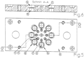
- Fig. 5 shows a top view of an exemplary support plate 8 for several ejector pins 5, e.g. the one in Fig. 2
- the support plate 8 has a through hole 15 for each ejector pin 5 to be accommodated, with a diameter that is larger than the shaft 6 for the purpose of floating accommodation (e.g. increased by 0.2 mm) and a recess 16 for the positive, play-free accommodation of the head 7 within the tolerances (note: parallel to the straight peripheral sections 11, larger tolerances - and thus greater clearance - than perpendicular to them, since this parallel direction does not need to be used to define the ejector pin angle position).
- Fig. 5 shows a top view of an exemplary support plate 8 for several ejector pins 5, e.g. the one in Fig. 2
- the support plate 8 has a through hole 15 for each ejector pin 5 to be accommodated, with a diameter that is larger than the shaft 6 for the purpose of floating accommodation (e.g. increased by 0.2
- the exemplary support plate 8 has two concentric circular arrangements of such bores 15 and recesses 16, the inner arrangement being designed for smaller ejector pins than the outer arrangement for larger ejector pins.
- the shape of the recesses 16 is complementary to that of the head 7 of the embodiment of Fig. 2 ; ie, the recesses 16 have two opposite straight peripheral sections 17, a further straight peripheral section 17' (with radii in between) and a curved peripheral section 18.
- peripheral sections 17, 17', 18 are complementary to those (11, 19, 12) of the head 7, which allows the head 7 to be received with practically no play, and thus a practically no play form fit (within the given tolerances) between the head 7 and the recess 16 despite the floating reception of the shaft 6 in the through hole 15.
- the slope S can have an angle to the longitudinal axis in a range of 1° to 25°. In another embodiment not claimed, this range is preferably in a range between 1° and 15°, particularly preferably the angle W is 5°. This serves for pre-centering for simple and quick assembly of the ejector pin 5′′′ in the support plate.
- the head 7 also has two opposite, straight, parallel circumferential sections 11, which, however, run at different distances from each other to the longitudinal axis 13 of the ejector pin 5′′′. This already ensures a clear definition of the installation position (360-degree symmetry).
- the two head circumferential surfaces 11, 11' have different lengths A and B, which are caused by the center offset from the center axis.
- the different head circumferential surface lengths A and B also ensure a clear definition of the installation position.
- the circumferential sections 12 also have different radii KR1 and KR2, which also enables the optical differentiation and recognition of the corresponding installation positions of the ejector pin 5′′′.
- the described embodiments of the invention allow an ejector pin anti-twisting device in the installation position in the support plate that does not lead to tension and is repeatable.
- the angular position of an ejector pin with anti-twist protection is precisely defined so that the shape of the front face of the ejector pin can be machined before it is installed in the carrier plates and molds.
- the two straight head surfaces 11, 11' form reference surfaces that can be used to align the ejector pin.
- the bevel S enables pre-centering.
Landscapes
- Engineering & Computer Science (AREA)
- Mechanical Engineering (AREA)
- Manufacturing & Machinery (AREA)
- Moulds For Moulding Plastics Or The Like (AREA)
Claims (12)
- Goupille d'éjection (5, 5', 5") destinée à éjecter des pièces moulées d'outils de coulée (1), comprenant :un arbre (6), etune tête (7) surmoulée sur celui-ci, dans laquelle la tête (7) est formée de telle manière que la goupille d'éjection (5, 5', 5") peut être montée seulement dans une position de montage unique dans une plaque de support (8) complémentaire,la tête (7) présente, vue dans la direction longitudinale de l'arbre, au moins deux sections périphériques rectilignes opposées (11), qui servent au blocage anti-rotation lorsque la goupille d'éjection (5, 5',5") est montée dans une plaque de support (8) complémentaire,dans laquellela tête (7) comprend sur son côté inférieur une surface d'appui (A) destinée à venir en appui sur la plaque de support (8) et présente, sur une section partielle supérieure de sa surface périphérique (K), une surface de contact (AF) destinée à venir en contact contre un évidement complémentaire dans la plaque de support (8),caractérisée en ce quela tête (7) présente sur une section partielle inférieure de sa surface périphérique (K) un biseau (5) destiné au centrage préalable, dans laquelle le biseau (5) est réalisé de manière périphérique autour de la tête (7) et de manière à jouxter la surface d'appui (A), et le biseau (5) présente un angle par rapport à l'axe longitudinal de l'arbre de 3 à 10 degrés.
- Goupille d'éjection (5) selon la revendication 1, dans laquelle les sections périphériques rectilignes opposées (11) s'étendent de manière parallèle les unes aux autres à distance égale par rapport au point central de l'arbre.
- Goupille d'éjection (5') selon la revendication 1, dans laquelle les sections périphériques rectilignes opposées (11) s'étendent de manière parallèle les unes par rapport aux autres à une distance différente par rapport au point central de l'arbre.
- Goupille d'éjection (5") selon la revendication 1, dans laquelle les sections périphériques rectilignes opposées (11, 11') ne s'étendent pas de manière parallèle les unes par rapport aux autres.
- Goupille d'éjection (5") selon la revendication 1, dans laquelle une ou plusieurs des sections périphériques rectilignes opposées (11, 11') sont composées de manière angulaire de sous-sections (11').
- Goupille d'éjection (5) selon l'une quelconque des revendications 1 à 3, dans laquelle la tête (7) présente pour créer la position de montage unique une autre section périphérique rectiligne (19) ainsi qu'une section périphérique incurvée (12) opposée à celle-ci.
- Procédé de fabrication d'une goupille d'éjection (5, 5', 5") selon l'une quelconque des revendications 1 à 6, dans lequel la tête (7) est fabriquée par refaçonnage du matériau de l'arbre et les sections périphériques rectilignes opposées (11) sont fabriquées par fraisage ou ponçage.
- Procédé de fabrication d'une goupille d'éjection (5, 5', 5") selon l'une quelconque des revendications 1 à 6, dans lequel la tête (7) avec les sections périphériques rectilignes opposées (11) et son biseau (S) est fabriquée par refaçonnage du matériau de l'arbre.
- Procédé selon la revendication 7 ou 8, dans lequel le refaçonnage est une compression centrée.
- Goupille d'éjection (5, 5', 5") selon l'une quelconque des revendications 1 à 6 ou fabriquée selon un des procédés 7 à 9, dans laquelle les sections périphériques rectilignes opposées (11) sont produites avec des tolérances inférieures ou égales à 0,02 mm.
- Ensemble plaque de support - goupille d'éjection avec une plaque de support (8) avec un ou plusieurs alésages (15) avec des réceptacles (16), dans lesquels des goupilles d'éjection (5, 5', 5") selon l'une quelconque des revendications 1 à 6 sont insérées, dans lequel les réceptacles (16) sont complémentaires à la forme de tête de goupille d'éjection et reçoivent les têtes (7), et les arbres (6) traversent les alésages (15), et les alésages présentent un diamètre bien plus grand que celui des arbres (6) de sorte que la position de la ou des goupilles d'éjection (5, 5', 5") dans la plaque de support (8) dans la direction transversale par rapport aux sections périphériques rectilignes opposées est définie par ces sections périphériques en coopération avec des sections périphériques (17) complémentaires à celles-ci des réceptacles (16), et non par les alésages (15).
- Ensemble plaque de support-goupille d'éjection selon la revendication 11, où l'alésage (15) présente un diamètre qui est plus grand que le diamètre de l'arbre (6) d'au moins 0,1 mm, en particulier d'au moins 0,2 mm.
Applications Claiming Priority (1)
| Application Number | Priority Date | Filing Date | Title |
|---|---|---|---|
| DE202019102059.8U DE202019102059U1 (de) | 2019-04-10 | 2019-04-10 | Auswerfstift mit Verdrehsicherung |
Publications (3)
| Publication Number | Publication Date |
|---|---|
| EP3722068A1 EP3722068A1 (fr) | 2020-10-14 |
| EP3722068B1 true EP3722068B1 (fr) | 2024-12-18 |
| EP3722068C0 EP3722068C0 (fr) | 2024-12-18 |
Family
ID=66816826
Family Applications (1)
| Application Number | Title | Priority Date | Filing Date |
|---|---|---|---|
| EP20169351.2A Active EP3722068B1 (fr) | 2019-04-10 | 2020-04-14 | Broche d'éjection pourvue d'une sécurité anti-rotation |
Country Status (4)
| Country | Link |
|---|---|
| EP (1) | EP3722068B1 (fr) |
| DE (1) | DE202019102059U1 (fr) |
| ES (1) | ES3014200T3 (fr) |
| PL (1) | PL3722068T3 (fr) |
Families Citing this family (3)
| Publication number | Priority date | Publication date | Assignee | Title |
|---|---|---|---|---|
| CN112371945B (zh) * | 2020-10-20 | 2021-10-08 | 苏州恒荣精密机电有限公司 | 一种带高、密、薄散热齿结构件模具 |
| DE202023103235U1 (de) | 2023-06-13 | 2023-07-11 | Knarr Vertriebs Gmbh | Auswerferstift zum Auswerfen von Formteilen |
| CN120619329B (zh) * | 2025-08-13 | 2025-10-21 | 长春鼎业天成新能源开发有限公司 | 一种具有防损脱模功能的集装箱角件铸造成型装置 |
Citations (5)
| Publication number | Priority date | Publication date | Assignee | Title |
|---|---|---|---|---|
| DE2427636A1 (de) * | 1974-06-07 | 1975-12-18 | Hasco Normalien Hasenclever Co | Auswerfereinheit in werkzeugformen |
| DE10355163A1 (de) * | 2003-11-26 | 2005-07-07 | Kunststoff-Zentrum in Leipzig gemeinnützige Gesellschaft mbH | Vorrichtung zum Entformen von Teilen aus einem Kunststoffverarbeitungswerkzeug mittels Ultraschall |
| WO2008014910A2 (fr) * | 2006-07-31 | 2008-02-07 | Drei-S-Werk Präzisionswerkzeuge GmbH & Co. Fertigungs-KG | Broche d'outil pour un moule d'outil et procédé de fabrication d'une telle broche d'outil |
| CN102672913A (zh) * | 2012-05-10 | 2012-09-19 | 浙江凯华模具有限公司 | 注塑模具斜导柱滑块式二次脱模机构 |
| CN202862533U (zh) * | 2012-11-13 | 2013-04-10 | 中国科学院宁波材料技术与工程研究所 | 树脂传递模塑模具及树脂传递模塑成型系统 |
Family Cites Families (4)
| Publication number | Priority date | Publication date | Assignee | Title |
|---|---|---|---|---|
| DE3345366A1 (de) | 1983-12-15 | 1985-06-27 | Hans-Joachim 4971 Hüllhorst Meyke | Auswerferstift fuer formen der kunststoff - verarbeitung |
| DE4316029C1 (de) | 1993-05-13 | 1994-11-17 | Rainer Knarr | Stufenloser Hülsenauswerfer |
| DE19607785A1 (de) * | 1996-03-01 | 1997-09-04 | Meyke Hans Joachim | Auswerferstift für Formen der Kunststoff-Verarbeitung |
| DE202004018293U1 (de) | 2004-11-25 | 2005-03-17 | Knarr Rainer | Auswerferstift |
-
2019
- 2019-04-10 DE DE202019102059.8U patent/DE202019102059U1/de active Active
-
2020
- 2020-04-14 EP EP20169351.2A patent/EP3722068B1/fr active Active
- 2020-04-14 PL PL20169351.2T patent/PL3722068T3/pl unknown
- 2020-04-14 ES ES20169351T patent/ES3014200T3/es active Active
Patent Citations (5)
| Publication number | Priority date | Publication date | Assignee | Title |
|---|---|---|---|---|
| DE2427636A1 (de) * | 1974-06-07 | 1975-12-18 | Hasco Normalien Hasenclever Co | Auswerfereinheit in werkzeugformen |
| DE10355163A1 (de) * | 2003-11-26 | 2005-07-07 | Kunststoff-Zentrum in Leipzig gemeinnützige Gesellschaft mbH | Vorrichtung zum Entformen von Teilen aus einem Kunststoffverarbeitungswerkzeug mittels Ultraschall |
| WO2008014910A2 (fr) * | 2006-07-31 | 2008-02-07 | Drei-S-Werk Präzisionswerkzeuge GmbH & Co. Fertigungs-KG | Broche d'outil pour un moule d'outil et procédé de fabrication d'une telle broche d'outil |
| CN102672913A (zh) * | 2012-05-10 | 2012-09-19 | 浙江凯华模具有限公司 | 注塑模具斜导柱滑块式二次脱模机构 |
| CN202862533U (zh) * | 2012-11-13 | 2013-04-10 | 中国科学院宁波材料技术与工程研究所 | 树脂传递模塑模具及树脂传递模塑成型系统 |
Non-Patent Citations (2)
| Title |
|---|
| 2 November 2016 (2016-11-02), Retrieved from the Internet <URL:https://web.archive.org/web/20161115000000*/http://www.biker-normalien.com/produkte/auswerferstifte/auswerferstifte-din-1530-form-d.html> [retrieved on 20230927] * |
| 31 July 2016 (2016-07-31), Retrieved from the Internet <URL:https://www.acbtools.nl/wp-content/uploads/2016/11/4020-DIN-1530-D.pdf> [retrieved on 20230927] * |
Also Published As
| Publication number | Publication date |
|---|---|
| ES3014200T3 (en) | 2025-04-21 |
| PL3722068T3 (pl) | 2025-06-30 |
| DE202019102059U1 (de) | 2019-05-27 |
| EP3722068C0 (fr) | 2024-12-18 |
| EP3722068A1 (fr) | 2020-10-14 |
Similar Documents
| Publication | Publication Date | Title |
|---|---|---|
| DE3934495C1 (fr) | ||
| EP3093080B1 (fr) | Dispositif de changement de matrice comprenant une matrice interchangeable et dome de matrice adaptés et procédé destiné au retrait et à l'insertion de la matrice interchangeable | |
| EP3468765B1 (fr) | Moule d'injection avec dispositif de centrage ajustable d'un noyau de moule | |
| EP3722068A1 (fr) | Broche d'éjection pourvue de sécurité anti-torsion | |
| EP3265304B1 (fr) | Presse à poudre et boîtier de mandrin avec de préférence plusieurs pistons mobiles pour un pressage transversal | |
| EP3265302B1 (fr) | Presse radiale | |
| EP0287777A2 (fr) | Dispositif de serrage d'outils ou de pièces, ayant une manche cylindrique | |
| WO2015114449A1 (fr) | Élément de tête d'outil pour la fabrication d'une tête d'outil, tête d'outil et moyen de réception d'outil ainsi que procédé de fabrication d'un élément de tête d'outil et d'une tête d'outil | |
| EP3595829B1 (fr) | Dispositif pour injecter un noyau | |
| EP3959058B1 (fr) | Unité de moulage par injection pour une machine de moulage par injection pour la transformation de matières plastiques | |
| EP0695619B1 (fr) | Moule d'injection | |
| EP0061072A2 (fr) | Moule d'injection | |
| EP3075504A1 (fr) | Dispositif de fabrication d'éléments de formage en béton dans une machine à mouler | |
| WO2020169462A1 (fr) | Corps monobloc de dispositif d'alimentation, destiné à être utilisé lors de la coulée de métaux | |
| DE202022104415U1 (de) | Schieberanordnung | |
| DE202016106336U1 (de) | Führungssäule mit Käfighalter eines Säulenführungsgestells | |
| EP4476057B1 (fr) | Agencement à coulisseau | |
| DE102006037709B4 (de) | Schnellspanneinheit, Schnellspannsystem, Maschinen- oder Werkzeugteil und Ur- oder Umformwerkzeug | |
| DE102020106191A1 (de) | Spritzgussform für tubusförmige Kunststoffteile | |
| WO2016097000A1 (fr) | Soupape de limitation de pression | |
| DE102019130415A1 (de) | Schutzkappe | |
| DE102005047620B9 (de) | Haltemodul für Rollkugeln | |
| EP4196343B1 (fr) | Presse à poudre permettant de produire des articles pressés | |
| DE10205730A1 (de) | Zweistufen-Auswerfer bei einem Formwerkzeug | |
| DE2639818A1 (de) | Selbstzentrierendes und selbstspannendes spannfutter fuer werkzeugmaschinen, insbesondere fuer drehbaenke |
Legal Events
| Date | Code | Title | Description |
|---|---|---|---|
| PUAI | Public reference made under article 153(3) epc to a published international application that has entered the european phase |
Free format text: ORIGINAL CODE: 0009012 |
|
| STAA | Information on the status of an ep patent application or granted ep patent |
Free format text: STATUS: THE APPLICATION HAS BEEN PUBLISHED |
|
| AK | Designated contracting states |
Kind code of ref document: A1 Designated state(s): AL AT BE BG CH CY CZ DE DK EE ES FI FR GB GR HR HU IE IS IT LI LT LU LV MC MK MT NL NO PL PT RO RS SE SI SK SM TR |
|
| AX | Request for extension of the european patent |
Extension state: BA ME |
|
| STAA | Information on the status of an ep patent application or granted ep patent |
Free format text: STATUS: REQUEST FOR EXAMINATION WAS MADE |
|
| 17P | Request for examination filed |
Effective date: 20210414 |
|
| RBV | Designated contracting states (corrected) |
Designated state(s): AL AT BE BG CH CY CZ DE DK EE ES FI FR GB GR HR HU IE IS IT LI LT LU LV MC MK MT NL NO PL PT RO RS SE SI SK SM TR |
|
| STAA | Information on the status of an ep patent application or granted ep patent |
Free format text: STATUS: EXAMINATION IS IN PROGRESS |
|
| TPAC | Observations filed by third parties |
Free format text: ORIGINAL CODE: EPIDOSNTIPA |
|
| 17Q | First examination report despatched |
Effective date: 20210716 |
|
| GRAP | Despatch of communication of intention to grant a patent |
Free format text: ORIGINAL CODE: EPIDOSNIGR1 |
|
| STAA | Information on the status of an ep patent application or granted ep patent |
Free format text: STATUS: GRANT OF PATENT IS INTENDED |
|
| INTG | Intention to grant announced |
Effective date: 20240708 |
|
| GRAS | Grant fee paid |
Free format text: ORIGINAL CODE: EPIDOSNIGR3 |
|
| GRAA | (expected) grant |
Free format text: ORIGINAL CODE: 0009210 |
|
| STAA | Information on the status of an ep patent application or granted ep patent |
Free format text: STATUS: THE PATENT HAS BEEN GRANTED |
|
| AK | Designated contracting states |
Kind code of ref document: B1 Designated state(s): AL AT BE BG CH CY CZ DE DK EE ES FI FR GB GR HR HU IE IS IT LI LT LU LV MC MK MT NL NO PL PT RO RS SE SI SK SM TR |
|
| REG | Reference to a national code |
Ref country code: CH Ref legal event code: EP |
|
| REG | Reference to a national code |
Ref country code: DE Ref legal event code: R096 Ref document number: 502020009978 Country of ref document: DE |
|
| REG | Reference to a national code |
Ref country code: IE Ref legal event code: FG4D Free format text: LANGUAGE OF EP DOCUMENT: GERMAN |
|
| U01 | Request for unitary effect filed |
Effective date: 20250114 |
|
| U07 | Unitary effect registered |
Designated state(s): AT BE BG DE DK EE FI FR IT LT LU LV MT NL PT RO SE SI Effective date: 20250120 |
|
| PG25 | Lapsed in a contracting state [announced via postgrant information from national office to epo] |
Ref country code: HR Free format text: LAPSE BECAUSE OF FAILURE TO SUBMIT A TRANSLATION OF THE DESCRIPTION OR TO PAY THE FEE WITHIN THE PRESCRIBED TIME-LIMIT Effective date: 20241218 |
|
| REG | Reference to a national code |
Ref country code: ES Ref legal event code: FG2A Ref document number: 3014200 Country of ref document: ES Kind code of ref document: T3 Effective date: 20250421 |
|
| PG25 | Lapsed in a contracting state [announced via postgrant information from national office to epo] |
Ref country code: NO Free format text: LAPSE BECAUSE OF FAILURE TO SUBMIT A TRANSLATION OF THE DESCRIPTION OR TO PAY THE FEE WITHIN THE PRESCRIBED TIME-LIMIT Effective date: 20250318 |
|
| PG25 | Lapsed in a contracting state [announced via postgrant information from national office to epo] |
Ref country code: GR Free format text: LAPSE BECAUSE OF FAILURE TO SUBMIT A TRANSLATION OF THE DESCRIPTION OR TO PAY THE FEE WITHIN THE PRESCRIBED TIME-LIMIT Effective date: 20250319 |
|
| PG25 | Lapsed in a contracting state [announced via postgrant information from national office to epo] |
Ref country code: RS Free format text: LAPSE BECAUSE OF FAILURE TO SUBMIT A TRANSLATION OF THE DESCRIPTION OR TO PAY THE FEE WITHIN THE PRESCRIBED TIME-LIMIT Effective date: 20250318 |
|
| U20 | Renewal fee for the european patent with unitary effect paid |
Year of fee payment: 6 Effective date: 20250424 |
|
| PG25 | Lapsed in a contracting state [announced via postgrant information from national office to epo] |
Ref country code: SM Free format text: LAPSE BECAUSE OF FAILURE TO SUBMIT A TRANSLATION OF THE DESCRIPTION OR TO PAY THE FEE WITHIN THE PRESCRIBED TIME-LIMIT Effective date: 20241218 |
|
| PGFP | Annual fee paid to national office [announced via postgrant information from national office to epo] |
Ref country code: PL Payment date: 20250401 Year of fee payment: 6 |
|
| PGFP | Annual fee paid to national office [announced via postgrant information from national office to epo] |
Ref country code: ES Payment date: 20250519 Year of fee payment: 6 |
|
| PG25 | Lapsed in a contracting state [announced via postgrant information from national office to epo] |
Ref country code: IS Free format text: LAPSE BECAUSE OF FAILURE TO SUBMIT A TRANSLATION OF THE DESCRIPTION OR TO PAY THE FEE WITHIN THE PRESCRIBED TIME-LIMIT Effective date: 20250418 |
|
| PG25 | Lapsed in a contracting state [announced via postgrant information from national office to epo] |
Ref country code: SK Free format text: LAPSE BECAUSE OF FAILURE TO SUBMIT A TRANSLATION OF THE DESCRIPTION OR TO PAY THE FEE WITHIN THE PRESCRIBED TIME-LIMIT Effective date: 20241218 |
|
| PGFP | Annual fee paid to national office [announced via postgrant information from national office to epo] |
Ref country code: CZ Payment date: 20250402 Year of fee payment: 6 |
|
| PLBE | No opposition filed within time limit |
Free format text: ORIGINAL CODE: 0009261 |
|
| STAA | Information on the status of an ep patent application or granted ep patent |
Free format text: STATUS: NO OPPOSITION FILED WITHIN TIME LIMIT |
|
| REG | Reference to a national code |
Ref country code: CH Ref legal event code: L10 Free format text: ST27 STATUS EVENT CODE: U-0-0-L10-L00 (AS PROVIDED BY THE NATIONAL OFFICE) Effective date: 20251029 |
|
| REG | Reference to a national code |
Ref country code: CH Ref legal event code: H13 Free format text: ST27 STATUS EVENT CODE: U-0-0-H10-H13 (AS PROVIDED BY THE NATIONAL OFFICE) Effective date: 20251125 |
|
| 26N | No opposition filed |
Effective date: 20250919 |
|
| PG25 | Lapsed in a contracting state [announced via postgrant information from national office to epo] |
Ref country code: MC Free format text: LAPSE BECAUSE OF FAILURE TO SUBMIT A TRANSLATION OF THE DESCRIPTION OR TO PAY THE FEE WITHIN THE PRESCRIBED TIME-LIMIT Effective date: 20241218 |
|
| GBPC | Gb: european patent ceased through non-payment of renewal fee |
Effective date: 20250414 |
|
| PG25 | Lapsed in a contracting state [announced via postgrant information from national office to epo] |
Ref country code: GB Free format text: LAPSE BECAUSE OF NON-PAYMENT OF DUE FEES Effective date: 20250414 |
|
| PG25 | Lapsed in a contracting state [announced via postgrant information from national office to epo] |
Ref country code: CH Free format text: LAPSE BECAUSE OF NON-PAYMENT OF DUE FEES Effective date: 20250430 |
|
| PG25 | Lapsed in a contracting state [announced via postgrant information from national office to epo] |
Ref country code: IE Free format text: LAPSE BECAUSE OF NON-PAYMENT OF DUE FEES Effective date: 20250414 |