EP3722799B1 - Procédé de détermination de la géométrie d'un objet en fonction des données du procédé de mesure non destructive - Google Patents
Procédé de détermination de la géométrie d'un objet en fonction des données du procédé de mesure non destructive Download PDFInfo
- Publication number
- EP3722799B1 EP3722799B1 EP19168532.0A EP19168532A EP3722799B1 EP 3722799 B1 EP3722799 B1 EP 3722799B1 EP 19168532 A EP19168532 A EP 19168532A EP 3722799 B1 EP3722799 B1 EP 3722799B1
- Authority
- EP
- European Patent Office
- Prior art keywords
- expert
- geometry
- data set
- grid
- defect
- Prior art date
- Legal status (The legal status is an assumption and is not a legal conclusion. Google has not performed a legal analysis and makes no representation as to the accuracy of the status listed.)
- Active
Links
Images



Classifications
-
- G—PHYSICS
- G01—MEASURING; TESTING
- G01N—INVESTIGATING OR ANALYSING MATERIALS BY DETERMINING THEIR CHEMICAL OR PHYSICAL PROPERTIES
- G01N27/00—Investigating or analysing materials by the use of electric, electrochemical, or magnetic means
- G01N27/72—Investigating or analysing materials by the use of electric, electrochemical, or magnetic means by investigating magnetic variables
- G01N27/82—Investigating or analysing materials by the use of electric, electrochemical, or magnetic means by investigating magnetic variables for investigating the presence of flaws
- G01N27/83—Investigating or analysing materials by the use of electric, electrochemical, or magnetic means by investigating magnetic variables for investigating the presence of flaws by investigating stray magnetic fields
-
- G—PHYSICS
- G01—MEASURING; TESTING
- G01N—INVESTIGATING OR ANALYSING MATERIALS BY DETERMINING THEIR CHEMICAL OR PHYSICAL PROPERTIES
- G01N27/00—Investigating or analysing materials by the use of electric, electrochemical, or magnetic means
- G01N27/72—Investigating or analysing materials by the use of electric, electrochemical, or magnetic means by investigating magnetic variables
- G01N27/82—Investigating or analysing materials by the use of electric, electrochemical, or magnetic means by investigating magnetic variables for investigating the presence of flaws
-
- G—PHYSICS
- G01—MEASURING; TESTING
- G01N—INVESTIGATING OR ANALYSING MATERIALS BY DETERMINING THEIR CHEMICAL OR PHYSICAL PROPERTIES
- G01N29/00—Investigating or analysing materials by the use of ultrasonic, sonic or infrasonic waves; Visualisation of the interior of objects by transmitting ultrasonic or sonic waves through the object
- G01N29/22—Details, e.g. general constructional or apparatus details
- G01N29/24—Probes
- G01N29/2412—Probes using the magnetostrictive properties of the material to be examined, e.g. electromagnetic acoustic transducers [EMAT]
-
- G—PHYSICS
- G01—MEASURING; TESTING
- G01N—INVESTIGATING OR ANALYSING MATERIALS BY DETERMINING THEIR CHEMICAL OR PHYSICAL PROPERTIES
- G01N29/00—Investigating or analysing materials by the use of ultrasonic, sonic or infrasonic waves; Visualisation of the interior of objects by transmitting ultrasonic or sonic waves through the object
- G01N29/44—Processing the detected response signal, e.g. electronic circuits specially adapted therefor
- G01N29/4409—Processing the detected response signal, e.g. electronic circuits specially adapted therefor by comparison
- G01N29/4427—Processing the detected response signal, e.g. electronic circuits specially adapted therefor by comparison with stored values, e.g. threshold values
-
- G—PHYSICS
- G01—MEASURING; TESTING
- G01N—INVESTIGATING OR ANALYSING MATERIALS BY DETERMINING THEIR CHEMICAL OR PHYSICAL PROPERTIES
- G01N29/00—Investigating or analysing materials by the use of ultrasonic, sonic or infrasonic waves; Visualisation of the interior of objects by transmitting ultrasonic or sonic waves through the object
- G01N29/44—Processing the detected response signal, e.g. electronic circuits specially adapted therefor
- G01N29/4409—Processing the detected response signal, e.g. electronic circuits specially adapted therefor by comparison
- G01N29/4436—Processing the detected response signal, e.g. electronic circuits specially adapted therefor by comparison with a reference signal
Definitions
- the invention relates to a method for determining the geometry of a metallic, in particular magnetizable object, in particular a pipe or a tank.
- Such objects are examined for defects using non-destructive measuring methods.
- the results of the measuring methods are evaluated in order to be able to draw conclusions about the type and/or size of defects. Based on this, it can then be determined how much load the object can be subjected to, for example, or whether and to what extent repairs or replacement of the object are necessary. In order to prevent unnecessary measures, it is important to be able to describe the defects and their geometry as precisely as possible.
- An example of an object to be examined in this way is a pipeline.
- One of the main tasks of pipeline inspections, especially with so-called intelligent pigs, is to predict safe operating conditions that result from the condition of the pipeline.
- Pipeline operators are particularly interested in the condition of any welds and the number and size of defects, on the basis of which a load limit and, depending on this, a maximum operating pressure can be set.
- the so-called "burst pressure”, ie the pressure at which a pipeline is destroyed, is used to quantitatively determine the load limit.
- Defects are, for example, areas with metal losses due to of corrosion, cracks or other weakenings on a wall of an object intended in particular for the storage or transport of liquid or gaseous media. These include, for example, pipes, pipelines or tanks.
- Non-destructive measuring methods can be used. While MFL examinations using the magnetic leakage flux density (MFL measuring method) are preferably used to find defects due to corrosion, other methods, in particular those using ultrasound, are used to detect cracks on the inside or outside of an object.
- These non-destructive measuring methods include electromagnetic-acoustic methods (EMAT methods), in which sound waves, in particular in the form of guided waves, are generated in the pipe wall of the object to be examined due to eddy current-induced magnetic fields, as well as methods that introduce ultrasound directly into the object wall, hereinafter referred to as ultrasound methods or UT methods. Cracks close to the surface, in particular smaller ones, are also searched for in the state of the art using eddy current measuring methods, hereinafter referred to as EC measuring methods.
- EMAT methods electromagnetic-acoustic methods
- MFL data magnetic flux leakage data
- MFL measurements magnetic flux leakage measurements
- the US 2016/0187523 A1 an electromagnetic sensor for non-destructive inspection of pipelines in boreholes.
- the US 2016/0187523 A1 The evaluation of the measured values obtained as described can be used to determine the number of pipes in a borehole, the dimensions of the pipes such as diameter and wall thickness, as well as the presence of defects such as corrosion, cracks, holes or decreasing wall thicknesses.
- US6,541,964 B1 shows a device for a non-destructive measuring method and a method for evaluating the measurement results in order to determine the hydride content in an electrically conductive substrate.
- the method is based on a method for determining layer thicknesses, in particular the thickness of an oxide layer, of fuel rods made of a zirconium alloy.
- the layer thicknesses and the hydride content of the substrate can be determined using the method of US6,541,964 B1 determined by evaluating data obtained from a single measurement procedure.
- an automated evaluation of the measurement data from the non-destructive measurement methods is desirable.
- the problem here is that the measurement results of the non-destructive measurement methods can be changed not only as a result of defects but also by local changes in the geometry of the object. These occur, for example, in the area of weld seams, attachments and/or built-in components of the object. These can be support structures attached to the object, clamps surrounding the object, measuring technology attached to the object, shut-off technology and/or branching pipes.
- sacrificial anodes may have been attached to the object as part of cathodic corrosion protection, or areas with defects identified in previous inspections may have been reinforced by applied material.
- sacrificial anodes may have been attached to the object as part of cathodic corrosion protection, or areas with defects identified in previous inspections may have been reinforced by applied material.
- the task is therefore to provide a method by which a geometry for a subsequent automated analysis of defects can be created on the basis of measurement data from at least one non-destructive measuring method, and on the basis of which a load-bearing limit of an object can be determined.
- a representation of the defect-free geometry of the object is created in the form of an object grid from the reference data set of the object generated by the measurement method.
- This can include representations of weld seams as well as attachments and/or built-in components.
- Such a representation of the real object measured using non-destructive measurement methods is a suitable starting point for the subsequent determination of defects or defect geometries and the calculation of the remaining load-bearing capacity of the object being examined.
- the determination of the object grid can be carried out for the object being examined as a whole or only for individual sub-areas. Several individual sub-areas can also be selected in such a way that the respective evaluations of the sub-areas as a whole correspond to an evaluation of the entire object being examined.
- a classification of anomaly-free areas and anomalous areas of the object is carried out on the basis of at least parts of the at least one reference data set.
- Anomalous areas of the reference data set are spatial areas to which measurement data that differ significantly from neighboring areas are assigned. It is assumed that these anomalies are due to defects.
- Anomaly-free areas are preferably connected areas in which the measured values measured by the non-destructive measuring method do not change or only change within a certain tolerance range, in which the gradient of the change is below certain limit values, the deviation of individual measured values from a mean is less than a certain threshold and/or the deviation of a mean in a local area from the mean values of the adjacent local areas is below a threshold.
- the areas affected by anomalies are then the remaining areas. It is also conceivable to use a neural network that has been trained for this task. In this case, explicitly specified threshold values are dispensed with. Alternatively, the areas affected by anomalies can also be determined, with the remaining areas then representing anomaly-free areas. These methods can also be combined.
- the method according to the invention creates an initial object grid, using previously known information about the object, for example the pipeline diameter and the wall thickness in the case of pipelines.
- a simulation routine calculates a prediction data set of the at least one non-destructive measuring method. For this purpose, a virtual measurement is simulated using the non-destructive measuring method on the basis of the initial object grid. Then at least parts of the prediction data set are compared with at least parts of the at least one reference data set, with the anomalous areas of the reference data set or the object being excluded from the comparison. If the compared data match sufficiently accurately, the initial object grid is considered to be sufficiently accurate. Representation of the actual shape of the defect-free object and can be used in further processes for evaluating the defects.
- an iterative adjustment of the initial object grid to the geometry of the object in the anomaly-free areas takes place in the IT unit.
- a new initial object grid is created and a new prediction data set is calculated for this by the simulation routine.
- a comparison of at least parts of the new prediction data set with at least parts of the at least one reference data set, excluding the anomalous areas, is carried out in order to determine the match. This is repeated until a stop criterion for the iterative adjustment is reached.
- the initial object grid then available is used as the object grid describing the geometry of the object.
- an interpolation or extrapolation of information from the reference data set and/or object grid from the anomaly-free areas to the anomaly-affected areas preferably takes place.
- the information from the anomaly-free areas can be interpolated and/or extrapolated to the anomaly-affected areas and an auxiliary reference data set obtained in this way can be used to determine the object grid. It is also conceivable to initially create an object grid only for the areas classified as anomaly-free.
- This object grid has In the anomalous areas, gaps appear which can then be closed by interpolation or extrapolation from the anomaly-free areas. In this way, an object grid representing the geometry of the object is obtained, which can then be used for further analyses of defects or defect geometries in the anomalous areas.
- the method according to the invention is carried out completely and in particular automatically on an EDP unit, which may optionally consist of several computers.
- the associated computer program can be a single program or it can be a program package comprising a plurality of program modules which, for example, run in a distributed manner on different EDP systems or subunits due to resources and can be stored there on respective EDP media.
- a computer has in particular the typical means of a data processing unit such as one or more processors, at least temporary memory (RAM), data communication means, display and/or input units.
- the simulation routine is set up by specifying parameters that represent the material properties of the object, the geometry of a sensor used in the non-destructive measuring method, the distance of the sensor from the object surface and/or operating conditions of the sensor.
- the simulation routine must be adapted to the specific problem to be solved in order to be able to calculate reliable solutions.
- a measurement is often carried out using the respective non-destructive measuring method on an object with a known geometry.
- the simulation routine simulates a virtual measuring run using this known geometry.
- the simulation routine can be considered set up if, when comparing the recorded measured values and the simulated measured values, the differences remain below a certain limit.
- the simulation routine then outputs sufficiently reliable results.
- the simulation routing can be set up by iteratively changing one or more parameters.
- parameters can be specified that represent known properties of the object to be measured or the measuring method used.
- the operating conditions can include, for example, the feed rate of the sensor, the magnetic field strength for magnetic sensors, the excitation frequency for ultrasonic sensors and/or the properties of a coupling medium. This makes setting up the simulation routine easier and faster.
- the classification into anomaly-free areas and anomaly-affected areas is carried out on the basis of at least parts of at least two reference data sets obtained by different non-destructive measuring methods.
- the classification can be carried out simultaneously on both reference data sets or one after the other. To do this, the data sets must be prepared in such a way that they match in terms of their location information. This ensures that a defect that is measured in both measuring methods can also be identified as the same defect.
- the combination of parts of reference data sets obtained by two different non-destructive measuring methods enables a more reliable classification.
- Certain measurement methods are more sensitive to certain defects than others. While MFL measurement methods and EC measurement methods are particularly well suited to detecting surface defects such as corrosion, the ultrasound-based EMAT and UT measurement methods are particularly well suited to detecting cracks and other structural changes inside the wall of the object.
- MFL measurement methods and EC measurement methods are particularly well suited to detecting surface defects such as corrosion
- the ultrasound-based EMAT and UT measurement methods are particularly well suited to detecting cracks and other structural changes inside the wall of the object.
- the aforementioned MFL, EMAT, UT and EC measuring methods are preferably used as non-destructive measuring methods.
- the method uses a first reference data set generated on the basis of an MFL measuring method, in particular with axial or circumferential magnetization, and at least one further reference data set generated on the basis of an eddy current, EMAT or ultrasound measuring method. If a measuring method such as an EMAT method generates a data set with several sub-data sets, e.g. due to sensors recording several signals, then all sub-data sets are preferably used in the method.
- the reference data sets are preferably amplitudes ("counts") integrated over time at the respective wall positions or measuring positions, the so-called A-scans.
- the reference data sets generated on the basis of MFL measurements can preferably be differentiated with regard to the direction of magnetization.
- an anomaly-free area is assigned to a predefined local element of the object. This is used when creating the initial object grid or inserted into the initial object grid. This step simplifies the creation of an initial object grid.
- the object examined using the non-destructive measurement method can contain weld seams, attachments and/or add-ons, or have another previously known locally modified geometry. The creation of the object grid can be made easier if this previously known information is used during creation.
- corresponding elements such as weld seams, add-ons such as support elements, clamps, reinforcing elements or, for example, sacrificial anodes of a cathodic rust protection, as well as sleeves attached for repair purposes are predefined in their shape and/or extent.
- the measurement results of the non-destructive measurement methods naturally look different in these areas than in areas of an unchanged wall of the object, for example the pipeline wall in pipelines.
- these changes are uniform and, compared to most defects, are large-scale.
- they are predictable because the position of the elements causing the change is known.
- the weld seams are particularly interesting, as they are regularly found in pipelines.
- the following Examination or evaluation of defects in the area of a weld seam is interesting. This cannot currently be carried out or can only be done with great effort.
- a detection can be carried out in the classification, for example whether it is a weld seam or a support structure.
- the element detected in this way can then be used with its known general shape or general dimensions when creating the initial object grid or can be subsequently inserted into the initial object grid at the appropriate point in order to adapt it to the actual shape of the object being examined.
- the respective local element is particularly preferably described using a parametric geometry model. This can significantly reduce the effort involved in creating the object grid.
- the previously known information about the local element is used for this purpose. For example, it can be known about a weld seam that it extends in the circumferential direction around the object and can be described with sufficient accuracy by a weld seam width and a superelevation.
- a predefined parametric geometry model of a local element can be adapted to the actual local shape of the object by varying just a few parameters.
- the process for creating an object grid is thereby significantly accelerated.
- a change in just one or more Parameters of the parametric geometry model can also be limited by certain limit values within which they can be modified. Such a limitation can minimize the risk of obtaining physically nonsensical results.
- the reliability of the method is increased.
- the initial object grid can be adapted in the iterative process by means of grid modification.
- the grid as such, in particular the connections between a grid point and its neighboring grid points or the grid elements, are retained. However, the position of a grid point or the distance to the neighboring grid points can be varied. If necessary, the grid can also be divided and new grid points inserted. Grid modifications can be carried out with relatively little computational effort. The process can therefore be carried out quickly and easily.
- the general topology of the grid is known. Grid elements that are less suitable for free, automatic grid creation can also be used.
- the initial object grid can also be created by calculating a new grid within a changed contour of the initial object grid. In this case, only the edge points of the object grid are moved and a new object grid is created.
- the simulation routine calculates a new prediction data set based on the new object grid.
- the object grid obtained is then used to determine defect geometries in the anomalous areas.
- the use of an object grid obtained according to the method according to the invention when determining a defect geometry also enables the defect geometry to be determined in areas of weld seams and/or attachments or built-ins in the object. Without creating a corresponding object grid, automated evaluation is difficult in these areas. An automated evaluation method must recognize whether a deviation of the measurement results from simulated measurement results of an expected object geometry, for example a simple pipe shape in pipelines, is due to defects or to modification of the measurement results by weld seams or attachments or built-ins.
- the method determines the geometry of one or more real, examined defects of a metallic and in particular magnetizable object, in particular a pipe or a tank, based on a reference data set of the object generated using different, non-destructive measuring methods.
- the object is at least partially represented on or by the at least two-dimensional, preferably three-dimensional object grid obtained using the method according to the invention in a computer unit.
- the method according to the invention comprises a determination, in particular a generation, of an initial defect geometry as the starting defect geometry.
- Initial defect geometry can be mapped directly onto the object grid or represented by it, but it can also be present in a parameter representation, for example on an at least two-dimensional defect grid.
- a determination, in particular a generation, of respective prediction data sets is carried out as initial prediction data sets on the basis of the common initial defect geometry. This is done by simulation or by assigning a measurement that matches the respective reference data set.
- an iterative adaptation of the initial defect geometry to the geometry of the real defect or defects is carried out by means of the computer unit, wherein this adaptation is preferably carried out by means of at least one, preferably several expert routines running in competition with one another and in particular parallel to one another, wherein in the or respective expert routines a respective expert defect geometry is generated by means of at least one separate algorithm or a separate search strategy and on the basis of the initial defect geometry.
- the expert routine has its own algorithm if at least one of the algorithms available to the expert routine for adapting the defect geometry differs at least partially from the algorithms of another expert routine.
- stochastic Processes are used to differentiate the algorithms of different expert routines.
- Each expert routine has at least one algorithm for adapting the defect geometry, preferably several algorithms are available to at least one expert routine. The selection of an algorithm based on stochastic processes can also be made or specified within an expert routine.
- a respective expert prediction data set is determined on the basis of the respective expert defect geometry, in particular by simulation or assignment of a measurement that matches the respective reference data set, wherein the expert defect geometry underlying the respective expert prediction data set is made available to at least one, preferably several and in particular all of the expert routines as a new initial defect geometry for further adaptation to the geometry of the real defect or defects if the respective expert prediction data set is more similar to the respective reference data set than the corresponding initial prediction data set and/or a fitness function that takes into account the at least two expert prediction data sets is improved. Subsequently, i.e. for the next comparisons of the respective expert defect geometries with the new initial defect geometry in the iteration, the expert prediction data sets belonging to the new initial defect geometry are used as new initial prediction data sets.
- a measure of similarity can also be formed via the fitness function, so that, for example, in one embodiment, a new initial defect geometry is provided by an expert routine for the further iteration steps even if an approximation - albeit significant - of only one of the simulated or assigned expert prediction data sets to the respective reference data set results.
- expert prediction data sets generated on the basis of the same initial defect geometry are compared with the respective reference data sets in a measurement method-specific manner, thus avoiding the disadvantages of the separate evaluation known from the prior art.
- a simulated EMAT scan is compared with the EMAT reference data set obtained on the basis of the real measurement
- a simulated MFL scan is compared with the MFL reference data set obtained on the basis of the real measurement, etc.
- the burst pressure of the object under investigation can be calculated at least 10% - 20% more accurately and, for example, a pipeline can be operated at higher pressures.
- the object under investigation needs to be inspected less often, e.g. by excavation.
- the combined evaluation of data obtained on the basis of different measurement methods minimizes the problem of singular, local solutions, i.e. the determination of the defect geometry is more robust.
- the associated expert defect geometry is made available as the initial defect geometry for the further and for the corresponding expert routine. Based on this solution, a next iteration step is started from this geometry, unless another expert routine has found a better solution, for example during its own defect geometry determination that is still ongoing, which is then made available to further or all expert routines.
- the expert routines compete with each other in such a way that the distribution of the resources of the IT unit, in particular in the form of computing time, to a respective expert routine is carried out depending on a success rate, which in particular takes into account the number of initial defect geometries calculated by the expert routine and made available for one or more other expert routines, and/or depending on a reduction of a fitness function, which in particular takes into account the number of expert prediction data sets generated for the reduction.
- the competition between the expert routines arises in particular from the fact that the part of the program designed as a monitoring routine then increasingly allocates resources to the respective expert routines, in particular in the form of computing time, CPU or GPU time is preferably allocated if these are more successful than other expert routines.
- An expert routine is successful if it has found a defect geometry that is more suitable for the reference data set, for example a simulated EMAT measurement, and this is made available to the other expert routines.
- the program can specify that none or individual expert routines do not fall below a certain percentage of computing time in order to avoid the problem of singular and exotic defect geometries or results from the individual routines. In this way, in the event that a previously successful expert routine only finds a local and not a global solution, a way out of the blockage situation that otherwise occurs in the state of the art can be found.
- the adjustment using the expert routines is carried out until an expert stop criterion is met.
- This is, for example, a residual difference in the measured and simulated measurement data. It can also be an external expert stop criterion, for example based on the available computing time or a particularly predeterminable number of iterations or a particularly predeterminable or specified or The expert stop criterion can also be a combination of these criteria.
- a load limit of an object that is subject to pressure at least during operation and is designed in particular as an oil, gas or water pipeline is determined, wherein in the method a data set describing one or more defects is used as an input data set in a calculation of the load limit, designed in particular as forward modeling, wherein the input data set is initially generated according to the method described above or below for determining the geometry of a defect.
- the advantageous representation of the defect geometry in particular as a non-parameterized true three-dimensional Geometry, i.e. as a two-dimensional surface with respective depth values, makes simplifications previously assumed to be necessary in the industry superfluous, so that for this reason too, an increase in the accuracy of defect determination as a whole is ensured in a way that was previously unattainable.
- the accuracy of the maximum depth is reduced to the level that can be achieved depending on the measurement accuracy, i.e. around ⁇ 5% of the wall thickness compared to around ⁇ 10% of the wall thickness for sizing according to the state of the art described above.
- the prediction of the load limit depending on the geometry of the defect achieves increases in accuracy, particularly for critical cases, from ⁇ 50% to ⁇ 5%.
- the advantage of the invention therefore lies in particular in an adequate representation of the defect geometry achieved for the first time, which is precisely what makes this increase possible.
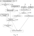
- Fig.1 shows the sequence of a possible implementation of the method according to the invention.
- a model for the non-destructive sensor 21 is created. This is required for the simulation of measurement data or reference data sets.
- a simulation routine is set up in step 22. This can be done by specifying known parameters that determine the material properties and properties of the used sensor. Alternatively or additionally, the parameters can be adjusted iteratively until the results of the simulation routine for the non-destructive measuring method used match the measurement data of the calibration measurement with sufficient accuracy based on the known geometry of the calibration object.
- the simulation routine can also be prepared and reused for several measurements using the non-destructive measuring method.
- one or more reference data sets are created.
- Fig.1 shows in step 2 the creation of a reference data set based on the data sets 1 of several measurement runs.
- a classification is carried out in step 23 into anomaly-free areas and anomaly-affected areas.
- an object grid representing the intact geometry of the object is created in step 24.
- Information from previous measurement runs in the object with no or fewer defects can also be used for this purpose.
- the object grid can be created and then completed by extrapolation and/or interpolation into the anomalous areas. It is also conceivable to carry out an interpolation and/or extrapolation based on the reference data sets from the anomaly-free areas into the anomalous areas.
- the creation of the object grid in step 24 is carried out by an iterative process.
- a first initial object grid is guessed or, for example, specified on the basis of an estimated object geometry. This is adjusted in an iterative process.
- An initial object grid can, for example, be a Fig. 2 If the object being examined has a weld in this area, an iterative adjustment of the initial object grid will be made until it has a shape that represents the weld, as shown in Fig. 3 and Fig. 4
- This adaptation can be done by mesh morphing, i.e. adapting the original object grid by moving individual grid points.
- a parametric description of the weld seam by means of a parametric geometry model can also be used.
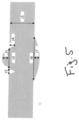
- Fig.5 shows such a parametric geometry model.
- the parameters describe the wall thickness of the object (zs), the respective extension of the weld on both sides (z 3 , z 6 ), the weld reinforcement (z 1 , z 7 ), as well as the width and depth of notches on the weld (z 2 , z 4 ).
- the object grid can thus be changed in the area of the weld by adjusting a small number of parameters.
- Data sets that are precisely matched to one another can be treated together, whereby the method according to the invention realizes the simultaneous treatment of the data sets by using a fitness function that takes into account the data sets to be considered together.
- step 7 the reference data sets available in step 6 are accessed, for which purpose an initial defect geometry is first determined as the starting defect geometry in step 8. This is done as described above on the basis of a neural network into which the reference data sets are read as input data sets.
- the solution of the neural network is then made available as one or more initial defect geometries x 1 ... x n for the individual expert modules.
- the number of parameter values describing the defect geometries can be kept as small as possible. This is achieved, for example, by means of a dynamic Grid adaptation is achieved. Since the number of depth values corresponds to the number of nodes in the defect grid 5, the number of nodes can also be the number of defect parameters. Starting with a comparatively coarse grid, this is gradually refined in relevant areas.
- the Fig.5 For example, for a given node spacing of 14 mm, a corresponding grid cell size of 14 mm x 14 mm and defect limits of 30%, 50% and 80% of the wall thickness, the Fig.5
- the refinement shown can be achieved in the relevant grid area, whereby those cells that exceed the above depth values are successively subdivided.
- the grid deformation then correlates with the assumed defect geometry, ie in areas of large gradients there is a larger number of grid points.
- a new expert defect geometry is calculated in step 14 for each defect in the respective expert routines and it is checked under 14.1 whether this needs to be made available to the other expert routines. This is the case if, as described above, a fitness function has been improved and no stop criterion has yet ended the defect finding. In this case, the iteration continues with the defect geometry or geometry that is made available to all expert routines. Otherwise, the The process ends with the determination of the defect geometries and in particular the specification of the accuracy of the solution. In addition, the burst pressure can be calculated based on the defect geometries found.
- the workflow of a group of expert routines 11 that are in competition with each other is simulated on the computer unit.
- the program can have various modules that can enter data into certain areas of the computer unit independently of each other and in particular not synchronized with each other so that they can be further processed there. This takes place in particular under the supervision of a monitoring routine 9 ( Fig.7 ).
- a plurality of expert routines 11 thus maintains a number of calculation slots 13 depending on the above-defined result, ie, for example, the number of initial defect geometries written into a common memory area 12, in order to generate expert defect geometries and/or to be able to carry out associated MFL simulations or, in the case of an independent MFL simulation module, to have them carried out.
- the simulations of the measurement data matching the individual expert defect geometries are also carried out under the supervision of the monitoring routine 9 in the simulation modules 16 for the purpose of creating the expert prediction data sets.
- the number of The number of program modules intended for carrying out simulations is equal to the number of slots.
- the monitoring routine 9 monitors the number of iterations and the resulting changes in the initial defect geometry and further monitors whether an associated stop criterion has been reached. The result is then calculated according to block 17, which corresponds to block 14.2 of Fig.6 corresponds to, is output.
- the number of calculation slots 13 available for an expert routine 11 and the simulation routines subsequently made available can vary such that a first expert routine can, for example, utilize up to 50% of the total computing time available for the calculation slots and simulation routines.
- the initial defect geometries are stored in the memory area 12.
- This can be a memory area accessible to the expert routines 11.
- Log files from the expert routines 11 and monitoring routine 9 as well as instructions for the expert routines 11 can also be stored there, which are then implemented independently by the expert routines 11. For example, this can be an interrupt command that is set when the stop criterion is reached.
- the expert routines 11 are independent program modules that generate new expert defect geometries and enter them into the simulation routines 16. Furthermore, the expert routines 11 can be used to A fitness function is generated based on the expert prediction data set and compared with the initial prediction data set stored in area 12. If the expert prediction data sets are more similar to the reference data sets overall than the data sets stored in area 12, these expert prediction data sets are then used as new initial prediction data sets.
- a new defect geometry is randomly generated in the expert routines 11.
- Machine learning algorithms or empirical rules can be used for this.
- These search strategies are based on an assumed probability distribution p(x,y) of grid points whose depth value results in a maximum reduction of the fitness function in order to determine a corrosion-based defect geometry.
- the probability function is used to identify N grid points (x n ,y n ).
- the parameter representation of the group of defects (x 1 ...x n ) already used above can also be assumed as the subject of the probability distribution, whereby for the purpose of simpler explanation, the probability distribution is referred to below in relation to N grid points (x,y) or (x n ,y n ).
- the depth function which in this case describes the depth D of the corrosion at the grid point, is changed by ⁇ D, with the sign of the change being randomly generated.
- Such an algorithm varies the defect geometry at positions where the simulated MFL measurement signal H the best for the best known solution has the largest difference to the measured signal H m .
- the monitoring routine 9 shown has two functions in particular: Firstly, it checks whether the stop criterion has been reached and secondly, the resources of the IT unit are allocated between the individual experts based on their success.
- the respective non-destructive measurements for the expert defect geometries are simulated.
- An expert routine can iterate until it finds a solution whose expert prediction data sets are better than the initial prediction data sets stored in area 12. If this is the case, the expert routine 11 can try to achieve further better solutions based on the already improved solution.
- the method according to the invention allows the condition of a pipe and thus the pressure that can be specified for safe operation of the pipeline to be specified much more realistically, while operational safety is still guaranteed.
- the method according to the invention with the expert routines competing for resources of the computer unit, means that such a result can be made available to pipeline operators more quickly or at least in the same evaluation time as with the prior art.
Landscapes
- Physics & Mathematics (AREA)
- Chemical & Material Sciences (AREA)
- General Health & Medical Sciences (AREA)
- General Physics & Mathematics (AREA)
- Life Sciences & Earth Sciences (AREA)
- Pathology (AREA)
- Analytical Chemistry (AREA)
- Biochemistry (AREA)
- Immunology (AREA)
- Health & Medical Sciences (AREA)
- Engineering & Computer Science (AREA)
- Signal Processing (AREA)
- Electromagnetism (AREA)
- Chemical Kinetics & Catalysis (AREA)
- Electrochemistry (AREA)
- Investigating Or Analyzing Materials By The Use Of Ultrasonic Waves (AREA)
- Analysing Materials By The Use Of Radiation (AREA)
Claims (14)
- Procédé de détermination de la géométrie d'un objet métallique, notamment magnétisable, notamment d'un tube ou d'un réservoir, présentant notamment un ou plusieurs défauts réels examinés, avec un ensemble de données de référence de l'objet généré sur la base d'au moins une mesure effectuée par au moins un procédé de mesure non destructif, le procédé de détermination comprenant de préférence une représentation au moins partielle de l'objet sur ou à travers une grille d'objets au moins tridimensionnelle à l'aide d'une unité informatique, une classification de zones exemptes d'anomalies et de zones affectées par des anomalies de l'objet étant effectuée sur la base d'au moins des parties de l'au moins un ensemble de données de référence, une grille d'objet initiale étant créée sur la base d'informations déjà connues sur l'objet, un ensemble de données de prédiction de l'au moins un procédé de mesure non destructif étant calculé à l'aide de la grille d'objet initiale par une routine de simulation, une comparaison au moins de parties de l'ensemble de données de prédiction à au moins des parties dudit au moins un ensemble de données de référence étant effectuée à l'exclusion des zones affectées par des anomalies et, en fonction d'au moins une mesure de précision, la grille d'objet initiale est utilisée comme grille d'objet décrivant la géométrie de l'objet ou une adaptation itérative de la grille d'objet initiale à la géométrie de l'objet dans les zones exemptes d'anomalies étant effectuée au moyen de l'unité informatique, une nouvelle grille d'objet initiale étant créée au cours de l'itération et pour cela un nouvel ensemble de données de prédiction étant calculé par la routine de simulation et une comparaison au moins de parties du nouvel ensemble de données de prédiction à au moins des parties de l'au moins un ensemble de données de référence étant effectuée à l'exclusion des zones affectées par des anomalies jusqu'à ce qu'un critère d'arrêt soit présent puis la présente grille d'objet initiale étant utilisée comme grille d'objet décrivant la géométrie de l'objet.
- Procédé selon la revendication 1, caractérisé en ce qu'une interpolation ou extrapolation d'informations de l'ensemble de données de référence et/ou de la grille d'objet étant effectuée depuis les zones exemptes d'anomalies vers les zones affectées par des anomalies.
- Procédé selon la revendication 1 ou 2, caractérisé en ce que la routine de simulation est ajustée par spécification de paramètres qui représentent les propriétés matérielles de l'objet, la géométrie d'un capteur utilisé dans le procédé de mesure non destructif, la distance du capteur à la surface de l'objet et/ou des conditions de fonctionnement du capteur.
- Procédé selon l'une des revendications précédentes, caractérisé en ce que la classification est effectuée sur la base au moins de parties d'au moins deux ensembles de données de référence obtenues par des procédés de mesure non destructifs différents.
- Procédé selon l'une des revendications précédentes, caractérisé par l'utilisation d'un premier ensemble de données de référence généré sur la base d'un procédé de mesure de densité de flux de dispersion magnétique, en particulier avec magnétisation axiale ou circonférentielle, et d'au moins un autre ensemble de données de référence généré sur la base d'un procédé de mesure par courants de Foucault, par une technique électro-magnéto-acoustique ou par ultrasons.
- Procédé selon l'une des revendications précédentes, caractérisé en ce que, lors de la classification, une association d'une zone exempte d'anomalie à un élément local prédéfini de l'objet est effectuée et cette association est utilisée lors de la création de la grille d'objet initiale ou est insérée dans la grille d'objet initiale.
- Procédé selon la revendication 6, caractérisé en ce que l'élément local, se présentant notamment sous forme de cordon de soudure, est décrit au moyen d'un modèle géométrique paramétrique.
- Procédé selon la revendication 7, caractérisé en ce qu'une variation d'au moins un paramètre du modèle géométrique paramétrique est effectuée lors de l'adaptation itérative de la grille d'objet initiale.
- Procédé selon l'une des revendications précédentes, caractérisé en ce que l'adaptation itérative de la grille d'objet initiale est effectuée par modification de la grille.
- Procédé selon l'une des revendications précédentes, caractérisé en ce que, lors de l'adaptation itérative de la grille d'objet initiale, la grille d'objet initiale est créée par calcul d'une nouvelle grille à l'intérieur d'un contour modifié de la grille d'objet initiale.
- Procédé selon l'une des revendications précédentes, caractérisé en ce que la grille d'objet est utilisée pour déterminer des géométries de défauts dans les zones affectées par des anomalies,
la géométrie d'un ou plusieurs défauts réels examinés d'un objet métallique et en particulier magnétisable, en particulier d'un tube ou d'un réservoir, étant déterminée au moyen d'au moins deux ensembles de données de référence de l'objet générés sur la base de procédés de mesures non destructifs différents,- l'objet étant au moins partiellement représenté sur ou à travers la grille d'objet au moins bidimensionnelle, de préférence tridimensionnelle, dans une unité informatique,- ledit procédé comprenant une détermination d'au moins une première géométrie de défaut comme géométrie de défaut initiale,- la détermination d'ensembles de données de prédiction respectifs comme ensembles de données de prédiction initiaux sur la base de la géométrie de défaut initiale par simulation ou attribution d'une mesure qui correspond à l'ensemble de données de référence respectif,- l'adaptation itérative de la géométrie de défaut initiale à la géométrie du ou des défauts réels au moyen de l'unité informatique et au moyen d'au moins une, de préférence plusieurs, routines expertes (11), notamment en compétition et plus particulièrement en parallèle,- une géométrie de défaut experte respective étant générée dans la ou les routines expertes respectives (11) au moyen d'au moins un algorithme propre et sur la base de la géométrie de défaut initiale,- sur la base de la géométrie de défaut experte respective, des ensembles de données de prédiction experts respectifs étant déterminés par simulation ou attribution d'une mesure qui correspond à l'ensemble de données de référence respectif,- et la géométrie de défaut experte sur laquelle sont basés les ensembles de données de prédiction experte respectifs étant ensuite mise à la disposition d'au moins une des routines expertes (11), en particulier de toutes, comme nouvelle géométrie de défaut initiale pour une adaptation ultérieure à la géométrie du ou des défauts réels lorsque les ensembles de données de prédiction experts d'une routine experte respective (11) sont davantage similaires aux ensembles de données de référence respectifs que les ensembles de données de prédiction initiaux et/ou qu'une fonction de fitness prenant en compte lesdites au moins deux ensembles de données de prédiction experts est améliorée,- puis les ensembles de données de prédiction experts appartenant à la nouvelle géométrie de défaut initiale sont utilisés comme nouveaux ensembles de données de prédiction initiaux,- l'adaptation itérative étant effectuée à l'aide des routines expertes (11) jusqu'à ce qu'un critère d'arrêt expert soit satisfait. - Procédé selon la revendication 11, caractérisé en ce qu'un ensemble de données basé sur un procédé de mesure par courants de Foucault, par une technique électro-magnéto-acoustique ou par ultrasons est utilisé comme premier ensemble de données de référence et au moins un autre ensemble de données de référence est utilisé comme ensemble de données généré sur la base d'un autre procédé de mesure issu de ce groupe de procédés de mesure.
- Procédé selon l'une des revendications 11 ou 12, caractérisé en ce que les routines expertes (11) fonctionnent en compétition les unes avec les autres de façon à effectuer une distribution des ressources de l'unité informatique vers une routine experte respective (11), notamment sous forme de temps de calcul, de préférence de temps CPU et/ou GPU, en fonction d'un taux de réussite qui prend notamment en compte le nombre de géométries de défaut initiales calculées par cette routine experte (11) et mises à disposition d'une ou plusieurs autres routines expertes (11), et/ou en fonction d'une réduction de la fonction fitness dans laquelle est notamment pris en compte le nombre d'ensembles de données de prédiction experts générés pour la réduction.
- Procédé de détermination d'une limite de charge d'un objet soumis à une pression au moins pendant le fonctionnement et en particulier conçu comme une canalisation de pétrole, de gaz ou d'eau, dans lequel un ensemble de données décrivant un ou plusieurs défauts est utilisé comme ensemble de données d'entrée lors d'un calcul de la limite de charge, caractérisé en ce que l'ensemble de données d'entrée est d'abord déterminé selon un procédé selon l'une des revendications précédentes.
Priority Applications (7)
| Application Number | Priority Date | Filing Date | Title |
|---|---|---|---|
| US17/602,950 US12140567B2 (en) | 2019-04-09 | 2020-04-09 | Method for determining the geometry of an object based on data from non-destructive measuring methods |
| BR112021020340-0A BR112021020340B1 (pt) | 2019-04-09 | 2020-04-09 | Método para determinar a geometria de um objeto metálico com base em dados de métodos de medição não destrutivos e método para determinar um limite de carga de um objeto sob pressão |
| AU2020271630A AU2020271630B2 (en) | 2019-04-09 | 2020-04-09 | Method for determining the geometry of an object on the basis of data from non-destructive measurement methods |
| CA3136522A CA3136522A1 (fr) | 2019-04-09 | 2020-04-09 | Procede pour determiner la geometrie d'un objet sur la base de donnees d'un procede de mesure non destructif |
| MX2021012415A MX2021012415A (es) | 2019-04-09 | 2020-04-09 | Metodo para determinar la geometria de un objeto en funcion de datos de metodos de medicion no destructivos. |
| PCT/EP2020/060188 WO2020208154A1 (fr) | 2019-04-09 | 2020-04-09 | Procédé pour déterminer la géométrie d'un objet sur la base de données d'un procédé de mesure non destructif |
| CONC2021/0015065A CO2021015065A2 (es) | 2019-04-09 | 2021-11-08 | Método para determinar la geometría de un objeto en función de datos de métodos de medición no destructivos |
Applications Claiming Priority (1)
| Application Number | Priority Date | Filing Date | Title |
|---|---|---|---|
| EP19168281 | 2019-04-09 |
Publications (3)
| Publication Number | Publication Date |
|---|---|
| EP3722799A1 EP3722799A1 (fr) | 2020-10-14 |
| EP3722799B1 true EP3722799B1 (fr) | 2024-09-11 |
| EP3722799C0 EP3722799C0 (fr) | 2024-09-11 |
Family
ID=66334171
Family Applications (1)
| Application Number | Title | Priority Date | Filing Date |
|---|---|---|---|
| EP19168532.0A Active EP3722799B1 (fr) | 2019-04-09 | 2019-04-10 | Procédé de détermination de la géométrie d'un objet en fonction des données du procédé de mesure non destructive |
Country Status (9)
| Country | Link |
|---|---|
| US (1) | US12140567B2 (fr) |
| EP (1) | EP3722799B1 (fr) |
| AR (1) | AR118631A1 (fr) |
| AU (1) | AU2020271630B2 (fr) |
| CA (1) | CA3136522A1 (fr) |
| CO (1) | CO2021015065A2 (fr) |
| ES (1) | ES2998810T3 (fr) |
| MX (1) | MX2021012415A (fr) |
| WO (1) | WO2020208154A1 (fr) |
Family Cites Families (12)
| Publication number | Priority date | Publication date | Assignee | Title |
|---|---|---|---|---|
| SE515544C2 (sv) * | 1998-11-26 | 2001-08-27 | Westinghouse Atom Ab | Förfarande och anordning för bestämning av hydridinnehåll |
| AU2003257362A1 (en) * | 2003-09-11 | 2005-03-29 | Autoform Engineering Gmbh | Determination of a model of a geometry of a metal sheet forming stage |
| US8788219B2 (en) * | 2010-05-11 | 2014-07-22 | Röntgen Technische Dienst B.V. | Method of determining an edge of an anomaly, method of determining interaction, method of aligning, computer program product, and data carrier |
| US9642560B2 (en) * | 2013-04-03 | 2017-05-09 | Brainlab Ag | Method and device for determining the orientation of a co-ordinate system of an anatomical object in a global co-ordinate system |
| US9562877B2 (en) * | 2014-07-11 | 2017-02-07 | Halliburton Energy Services, Inc. | Evaluation tool for concentric wellbore casings |
| US10613244B2 (en) * | 2014-07-11 | 2020-04-07 | Halliburton Energy Services, Inc. | Focused symmetric pipe inspection tools |
| US10559103B2 (en) * | 2015-06-12 | 2020-02-11 | Amada Holdings Co., Ltd. | Generation of geometry of objects |
| GB2554308B (en) | 2015-07-10 | 2021-04-07 | Halliburton Energy Services Inc | High quality visualization in a corrosion inspection tool for multiple pipes |
| ES3040734T3 (en) * | 2017-10-06 | 2025-11-04 | Rosen Ip Ag | Method for determining the geometry of a defect and for determining a load capacity limit |
| ES2903199T3 (es) * | 2019-04-09 | 2022-03-31 | Rosen Swiss Ag | Método para la determinación de la geometría de un punto defectuoso y para la determinación de un límite de la capacidad de carga |
| ES2942784T3 (es) * | 2019-04-09 | 2023-06-06 | Rosen Swiss Ag | Procedimiento para la determinación de la geometría de un defecto sobre la base de procedimientos de medición no destructivos utilizando inversión directa |
| DE102019121806A1 (de) * | 2019-08-13 | 2021-02-18 | Volume Graphics Gmbh | Computerimplementiertes Verfahren zum Ändern einer Modell-Geometrie eines Objekts |
-
2019
- 2019-04-10 ES ES19168532T patent/ES2998810T3/es active Active
- 2019-04-10 EP EP19168532.0A patent/EP3722799B1/fr active Active
-
2020
- 2020-04-08 AR ARP200100998A patent/AR118631A1/es active IP Right Grant
- 2020-04-09 WO PCT/EP2020/060188 patent/WO2020208154A1/fr not_active Ceased
- 2020-04-09 US US17/602,950 patent/US12140567B2/en active Active
- 2020-04-09 CA CA3136522A patent/CA3136522A1/fr active Pending
- 2020-04-09 AU AU2020271630A patent/AU2020271630B2/en active Active
- 2020-04-09 MX MX2021012415A patent/MX2021012415A/es unknown
-
2021
- 2021-11-08 CO CONC2021/0015065A patent/CO2021015065A2/es unknown
Also Published As
| Publication number | Publication date |
|---|---|
| AU2020271630B2 (en) | 2023-08-17 |
| AR118631A1 (es) | 2021-10-20 |
| CO2021015065A2 (es) | 2021-11-19 |
| MX2021012415A (es) | 2022-01-19 |
| BR112021020340A2 (pt) | 2021-12-07 |
| CA3136522A1 (fr) | 2020-10-15 |
| AU2020271630A1 (en) | 2021-11-04 |
| EP3722799C0 (fr) | 2024-09-11 |
| US12140567B2 (en) | 2024-11-12 |
| EP3722799A1 (fr) | 2020-10-14 |
| ES2998810T3 (en) | 2025-02-21 |
| US20220308018A1 (en) | 2022-09-29 |
| WO2020208154A1 (fr) | 2020-10-15 |
Similar Documents
| Publication | Publication Date | Title |
|---|---|---|
| EP3722800B1 (fr) | Procédé de détermination de la géométrie d'un point défectueux sur la base d'un procédé de mesure non destructive à l'aide d'une inversion directe | |
| DE102019102484A1 (de) | Verarbeitung von dreidimensionalen Bilddatensätzen | |
| EP3467489B1 (fr) | Procédé de détermination de la géométrie d'un défaut et de détermination de la capacité de charge | |
| EP3956736B1 (fr) | Procédé mis en oeuvre par ordinateur pour la détermination de défauts d'un objet fabriqué au moyen d'un processus de fabrication additive | |
| EP3722798B1 (fr) | Procédé de détermination de la géométrie d'un point défectueux et de détermination de la capacité de charge | |
| DE112018003282T5 (de) | Riss-Evaluierungskriteriums-Formulierungsverfahren, Riss-Evaluierungsverfahren durch interne Fehlerinspektion und Wartungsverwaltungsverfahren | |
| DE112018003588T5 (de) | Restlebensdauer-Bewertungsverfahren und Instandhaltungsverwaltungsverfahren | |
| DE102013211616A1 (de) | Verfahren und Vorrichtung zur Defektgrößenbewertung | |
| DE102019121285A1 (de) | Systeme und Verfahren zur Lokalisierung systematischer Fehler mittels physical failure analysis (PFA) | |
| EP1451689A2 (fr) | Procede et systeme de traitement d'hypotheses d'erreurs | |
| EP3722799A1 (fr) | Procédé de détermination de la géométrie d'un objet en fonction des données du procédé de mesure non destructive | |
| EP1421559B1 (fr) | Dispositif et procede permettant d'evaluer la qualite d'un objet | |
| DE102016200779A1 (de) | Untersuchungsverfahren für ein zu wartendes hohles Bauteil einer Strömungsmaschine | |
| DE102019220090B3 (de) | Verfahren und Vorrichtung zum automatisierten Bewerten eines Kernbruchdefektes in einem Hohlraum in einem Gussbauteil | |
| DE102007036822B4 (de) | Verfahren zur Modifikation fertiger Maschinenkomponentenschmiedeteile für die Ultraschallprüfungs-Erfassung | |
| DE102019201069A1 (de) | Verfahren zum Ermitteln einer Prüflingsorientierung für eine 2D-Röntgenanlage | |
| DE102018110940A1 (de) | Verfahren zur Bestimmung von Fehlstellen eines metallischen Objekts | |
| WO2026062154A1 (fr) | Procédé d'apprentissage d'un réseau neuronal pour déterminer la géométrie de défauts sur la base de procédés de mesure non destructive | |
| DE102024108828A1 (de) | Verfahren und Vorrichtung zur Überprüfung einer Oberfläche eines Bauteils | |
| DE102010006106B3 (de) | Verfahren zur Ermittlung zumindest eines Teils einer Mittellinie eines Hohlorgans, Recheneinheit und Datenträger | |
| DE102024202246A1 (de) | Verfahren zum Erzeugen eines Trainingsdatensatzes | |
| DE102019123826A1 (de) | Computerimplementiertes Verfahren zum Erstellen eines Netzes zum Simulieren eines Objekts | |
| DE102019118924A1 (de) | Verfahren und Vorrichtung zur Generierung von Trainingsdaten für ein maschinelles Lernverfahren zum Bestimmen von Merkmalen von Strukturauffälligkeiten eines räumlich ausgedehnten Objekts | |
| WO2010046117A2 (fr) | Procédé et tomodensitomètre à rayons x pour examiner un objet par tomodensitométrie | |
| DE202014105831U1 (de) | Vorrichtung zur Ermittlung und Beurteilung der Festigkeit von Bauteilen anhand der Porosität in einem statisch und/oder zyklisch belasteten Gussbauteil |
Legal Events
| Date | Code | Title | Description |
|---|---|---|---|
| PUAI | Public reference made under article 153(3) epc to a published international application that has entered the european phase |
Free format text: ORIGINAL CODE: 0009012 |
|
| STAA | Information on the status of an ep patent application or granted ep patent |
Free format text: STATUS: THE APPLICATION HAS BEEN PUBLISHED |
|
| AK | Designated contracting states |
Kind code of ref document: A1 Designated state(s): AL AT BE BG CH CY CZ DE DK EE ES FI FR GB GR HR HU IE IS IT LI LT LU LV MC MK MT NL NO PL PT RO RS SE SI SK SM TR |
|
| AX | Request for extension of the european patent |
Extension state: BA ME |
|
| STAA | Information on the status of an ep patent application or granted ep patent |
Free format text: STATUS: REQUEST FOR EXAMINATION WAS MADE |
|
| 17P | Request for examination filed |
Effective date: 20210412 |
|
| RBV | Designated contracting states (corrected) |
Designated state(s): AL AT BE BG CH CY CZ DE DK EE ES FI FR GB GR HR HU IE IS IT LI LT LU LV MC MK MT NL NO PL PT RO RS SE SI SK SM TR |
|
| STAA | Information on the status of an ep patent application or granted ep patent |
Free format text: STATUS: EXAMINATION IS IN PROGRESS |
|
| 17Q | First examination report despatched |
Effective date: 20220405 |
|
| RAP1 | Party data changed (applicant data changed or rights of an application transferred) |
Owner name: ROSEN IP AG |
|
| REG | Reference to a national code |
Ref country code: DE Ipc: G01N0029240000 Ref country code: DE Ref legal event code: R079 Ref document number: 502019012084 Country of ref document: DE Free format text: PREVIOUS MAIN CLASS: G01N0027830000 Ipc: G01N0029240000 |
|
| GRAP | Despatch of communication of intention to grant a patent |
Free format text: ORIGINAL CODE: EPIDOSNIGR1 |
|
| STAA | Information on the status of an ep patent application or granted ep patent |
Free format text: STATUS: GRANT OF PATENT IS INTENDED |
|
| RIC1 | Information provided on ipc code assigned before grant |
Ipc: G01N 27/83 20060101ALI20240422BHEP Ipc: G01N 29/24 20060101AFI20240422BHEP |
|
| INTG | Intention to grant announced |
Effective date: 20240513 |
|
| GRAS | Grant fee paid |
Free format text: ORIGINAL CODE: EPIDOSNIGR3 |
|
| GRAA | (expected) grant |
Free format text: ORIGINAL CODE: 0009210 |
|
| STAA | Information on the status of an ep patent application or granted ep patent |
Free format text: STATUS: THE PATENT HAS BEEN GRANTED |
|
| AK | Designated contracting states |
Kind code of ref document: B1 Designated state(s): AL AT BE BG CH CY CZ DE DK EE ES FI FR GB GR HR HU IE IS IT LI LT LU LV MC MK MT NL NO PL PT RO RS SE SI SK SM TR |
|
| REG | Reference to a national code |
Ref country code: GB Ref legal event code: FG4D Free format text: NOT ENGLISH |
|
| REG | Reference to a national code |
Ref country code: CH Ref legal event code: EP |
|
| REG | Reference to a national code |
Ref country code: DE Ref legal event code: R096 Ref document number: 502019012084 Country of ref document: DE |
|
| REG | Reference to a national code |
Ref country code: IE Ref legal event code: FG4D Free format text: LANGUAGE OF EP DOCUMENT: GERMAN |
|
| U01 | Request for unitary effect filed |
Effective date: 20240911 |
|
| U07 | Unitary effect registered |
Designated state(s): AT BE BG DE DK EE FI FR IT LT LU LV MT NL PT RO SE SI Effective date: 20240917 |
|
| PG25 | Lapsed in a contracting state [announced via postgrant information from national office to epo] |
Ref country code: GR Free format text: LAPSE BECAUSE OF FAILURE TO SUBMIT A TRANSLATION OF THE DESCRIPTION OR TO PAY THE FEE WITHIN THE PRESCRIBED TIME-LIMIT Effective date: 20241212 |
|
| PG25 | Lapsed in a contracting state [announced via postgrant information from national office to epo] |
Ref country code: HR Free format text: LAPSE BECAUSE OF FAILURE TO SUBMIT A TRANSLATION OF THE DESCRIPTION OR TO PAY THE FEE WITHIN THE PRESCRIBED TIME-LIMIT Effective date: 20240911 |
|
| PG25 | Lapsed in a contracting state [announced via postgrant information from national office to epo] |
Ref country code: RS Free format text: LAPSE BECAUSE OF FAILURE TO SUBMIT A TRANSLATION OF THE DESCRIPTION OR TO PAY THE FEE WITHIN THE PRESCRIBED TIME-LIMIT Effective date: 20241211 |
|
| PG25 | Lapsed in a contracting state [announced via postgrant information from national office to epo] |
Ref country code: RS Free format text: LAPSE BECAUSE OF FAILURE TO SUBMIT A TRANSLATION OF THE DESCRIPTION OR TO PAY THE FEE WITHIN THE PRESCRIBED TIME-LIMIT Effective date: 20241211 Ref country code: HR Free format text: LAPSE BECAUSE OF FAILURE TO SUBMIT A TRANSLATION OF THE DESCRIPTION OR TO PAY THE FEE WITHIN THE PRESCRIBED TIME-LIMIT Effective date: 20240911 Ref country code: GR Free format text: LAPSE BECAUSE OF FAILURE TO SUBMIT A TRANSLATION OF THE DESCRIPTION OR TO PAY THE FEE WITHIN THE PRESCRIBED TIME-LIMIT Effective date: 20241212 |
|
| REG | Reference to a national code |
Ref country code: ES Ref legal event code: FG2A Ref document number: 2998810 Country of ref document: ES Kind code of ref document: T3 Effective date: 20250221 |
|
| PG25 | Lapsed in a contracting state [announced via postgrant information from national office to epo] |
Ref country code: IS Free format text: LAPSE BECAUSE OF FAILURE TO SUBMIT A TRANSLATION OF THE DESCRIPTION OR TO PAY THE FEE WITHIN THE PRESCRIBED TIME-LIMIT Effective date: 20250111 |
|
| PG25 | Lapsed in a contracting state [announced via postgrant information from national office to epo] |
Ref country code: SM Free format text: LAPSE BECAUSE OF FAILURE TO SUBMIT A TRANSLATION OF THE DESCRIPTION OR TO PAY THE FEE WITHIN THE PRESCRIBED TIME-LIMIT Effective date: 20240911 |
|
| PG25 | Lapsed in a contracting state [announced via postgrant information from national office to epo] |
Ref country code: CZ Free format text: LAPSE BECAUSE OF FAILURE TO SUBMIT A TRANSLATION OF THE DESCRIPTION OR TO PAY THE FEE WITHIN THE PRESCRIBED TIME-LIMIT Effective date: 20240911 Ref country code: PL Free format text: LAPSE BECAUSE OF FAILURE TO SUBMIT A TRANSLATION OF THE DESCRIPTION OR TO PAY THE FEE WITHIN THE PRESCRIBED TIME-LIMIT Effective date: 20240911 |
|
| PG25 | Lapsed in a contracting state [announced via postgrant information from national office to epo] |
Ref country code: SK Free format text: LAPSE BECAUSE OF FAILURE TO SUBMIT A TRANSLATION OF THE DESCRIPTION OR TO PAY THE FEE WITHIN THE PRESCRIBED TIME-LIMIT Effective date: 20240911 |
|
| U20 | Renewal fee for the european patent with unitary effect paid |
Year of fee payment: 7 Effective date: 20250424 |
|
| PGFP | Annual fee paid to national office [announced via postgrant information from national office to epo] |
Ref country code: ES Payment date: 20250519 Year of fee payment: 7 |
|
| PGFP | Annual fee paid to national office [announced via postgrant information from national office to epo] |
Ref country code: NO Payment date: 20250422 Year of fee payment: 7 |
|
| PLBE | No opposition filed within time limit |
Free format text: ORIGINAL CODE: 0009261 |
|
| STAA | Information on the status of an ep patent application or granted ep patent |
Free format text: STATUS: NO OPPOSITION FILED WITHIN TIME LIMIT |
|
| 26N | No opposition filed |
Effective date: 20250612 |
|
| REG | Reference to a national code |
Ref country code: CH Ref legal event code: H13 Free format text: ST27 STATUS EVENT CODE: U-0-0-H10-H13 (AS PROVIDED BY THE NATIONAL OFFICE) Effective date: 20251125 |
|
| PG25 | Lapsed in a contracting state [announced via postgrant information from national office to epo] |
Ref country code: MC Free format text: LAPSE BECAUSE OF FAILURE TO SUBMIT A TRANSLATION OF THE DESCRIPTION OR TO PAY THE FEE WITHIN THE PRESCRIBED TIME-LIMIT Effective date: 20240911 |
|
| PG25 | Lapsed in a contracting state [announced via postgrant information from national office to epo] |
Ref country code: CH Free format text: LAPSE BECAUSE OF NON-PAYMENT OF DUE FEES Effective date: 20250430 |
|
| PGFP | Annual fee paid to national office [announced via postgrant information from national office to epo] |
Ref country code: GB Payment date: 20260324 Year of fee payment: 8 |
|
| PG25 | Lapsed in a contracting state [announced via postgrant information from national office to epo] |
Ref country code: IE Free format text: LAPSE BECAUSE OF NON-PAYMENT OF DUE FEES Effective date: 20250410 |