EP3722801B1 - Ultrasonic flaw detection method - Google Patents
Ultrasonic flaw detection method Download PDFInfo
- Publication number
- EP3722801B1 EP3722801B1 EP17933982.5A EP17933982A EP3722801B1 EP 3722801 B1 EP3722801 B1 EP 3722801B1 EP 17933982 A EP17933982 A EP 17933982A EP 3722801 B1 EP3722801 B1 EP 3722801B1
- Authority
- EP
- European Patent Office
- Prior art keywords
- mode
- flaw
- specimen
- ultrasonic
- ultrasound waves
- Prior art date
- Legal status (The legal status is an assumption and is not a legal conclusion. Google has not performed a legal analysis and makes no representation as to the accuracy of the status listed.)
- Active
Links
Images




Classifications
-
- G—PHYSICS
- G01—MEASURING; TESTING
- G01N—INVESTIGATING OR ANALYSING MATERIALS BY DETERMINING THEIR CHEMICAL OR PHYSICAL PROPERTIES
- G01N29/00—Investigating or analysing materials by the use of ultrasonic, sonic or infrasonic waves; Visualisation of the interior of objects by transmitting ultrasonic or sonic waves through the object
- G01N29/04—Analysing solids
- G01N29/07—Analysing solids by measuring propagation velocity or propagation time of acoustic waves
-
- G—PHYSICS
- G01—MEASURING; TESTING
- G01N—INVESTIGATING OR ANALYSING MATERIALS BY DETERMINING THEIR CHEMICAL OR PHYSICAL PROPERTIES
- G01N29/00—Investigating or analysing materials by the use of ultrasonic, sonic or infrasonic waves; Visualisation of the interior of objects by transmitting ultrasonic or sonic waves through the object
- G01N29/04—Analysing solids
- G01N29/043—Analysing solids in the interior, e.g. by shear waves
-
- G—PHYSICS
- G01—MEASURING; TESTING
- G01N—INVESTIGATING OR ANALYSING MATERIALS BY DETERMINING THEIR CHEMICAL OR PHYSICAL PROPERTIES
- G01N29/00—Investigating or analysing materials by the use of ultrasonic, sonic or infrasonic waves; Visualisation of the interior of objects by transmitting ultrasonic or sonic waves through the object
- G01N29/04—Analysing solids
- G01N29/06—Visualisation of the interior, e.g. acoustic microscopy
- G01N29/0654—Imaging
- G01N29/069—Defect imaging, localisation and sizing using, e.g. time of flight diffraction [TOFD], synthetic aperture focusing technique [SAFT], Amplituden-Laufzeit-Ortskurven [ALOK] technique
-
- G—PHYSICS
- G01—MEASURING; TESTING
- G01N—INVESTIGATING OR ANALYSING MATERIALS BY DETERMINING THEIR CHEMICAL OR PHYSICAL PROPERTIES
- G01N29/00—Investigating or analysing materials by the use of ultrasonic, sonic or infrasonic waves; Visualisation of the interior of objects by transmitting ultrasonic or sonic waves through the object
- G01N29/04—Analysing solids
- G01N29/11—Analysing solids by measuring attenuation of acoustic waves
-
- G—PHYSICS
- G01—MEASURING; TESTING
- G01N—INVESTIGATING OR ANALYSING MATERIALS BY DETERMINING THEIR CHEMICAL OR PHYSICAL PROPERTIES
- G01N29/00—Investigating or analysing materials by the use of ultrasonic, sonic or infrasonic waves; Visualisation of the interior of objects by transmitting ultrasonic or sonic waves through the object
- G01N29/22—Details, e.g. general constructional or apparatus details
- G01N29/221—Arrangements for directing or focusing the acoustical waves
-
- G—PHYSICS
- G01—MEASURING; TESTING
- G01N—INVESTIGATING OR ANALYSING MATERIALS BY DETERMINING THEIR CHEMICAL OR PHYSICAL PROPERTIES
- G01N29/00—Investigating or analysing materials by the use of ultrasonic, sonic or infrasonic waves; Visualisation of the interior of objects by transmitting ultrasonic or sonic waves through the object
- G01N29/22—Details, e.g. general constructional or apparatus details
- G01N29/24—Probes
-
- G—PHYSICS
- G01—MEASURING; TESTING
- G01N—INVESTIGATING OR ANALYSING MATERIALS BY DETERMINING THEIR CHEMICAL OR PHYSICAL PROPERTIES
- G01N29/00—Investigating or analysing materials by the use of ultrasonic, sonic or infrasonic waves; Visualisation of the interior of objects by transmitting ultrasonic or sonic waves through the object
- G01N29/22—Details, e.g. general constructional or apparatus details
- G01N29/24—Probes
- G01N29/2487—Directing probes, e.g. angle probes
-
- G—PHYSICS
- G01—MEASURING; TESTING
- G01N—INVESTIGATING OR ANALYSING MATERIALS BY DETERMINING THEIR CHEMICAL OR PHYSICAL PROPERTIES
- G01N29/00—Investigating or analysing materials by the use of ultrasonic, sonic or infrasonic waves; Visualisation of the interior of objects by transmitting ultrasonic or sonic waves through the object
- G01N29/22—Details, e.g. general constructional or apparatus details
- G01N29/26—Arrangements for orientation or scanning by relative movement of the head and the sensor
-
- G—PHYSICS
- G01—MEASURING; TESTING
- G01N—INVESTIGATING OR ANALYSING MATERIALS BY DETERMINING THEIR CHEMICAL OR PHYSICAL PROPERTIES
- G01N29/00—Investigating or analysing materials by the use of ultrasonic, sonic or infrasonic waves; Visualisation of the interior of objects by transmitting ultrasonic or sonic waves through the object
- G01N29/22—Details, e.g. general constructional or apparatus details
- G01N29/26—Arrangements for orientation or scanning by relative movement of the head and the sensor
- G01N29/262—Arrangements for orientation or scanning by relative movement of the head and the sensor by electronic orientation or focusing, e.g. with phased arrays
-
- G—PHYSICS
- G01—MEASURING; TESTING
- G01N—INVESTIGATING OR ANALYSING MATERIALS BY DETERMINING THEIR CHEMICAL OR PHYSICAL PROPERTIES
- G01N29/00—Investigating or analysing materials by the use of ultrasonic, sonic or infrasonic waves; Visualisation of the interior of objects by transmitting ultrasonic or sonic waves through the object
- G01N29/44—Processing the detected response signal, e.g. electronic circuits specially adapted therefor
-
- G—PHYSICS
- G01—MEASURING; TESTING
- G01N—INVESTIGATING OR ANALYSING MATERIALS BY DETERMINING THEIR CHEMICAL OR PHYSICAL PROPERTIES
- G01N29/00—Investigating or analysing materials by the use of ultrasonic, sonic or infrasonic waves; Visualisation of the interior of objects by transmitting ultrasonic or sonic waves through the object
- G01N29/44—Processing the detected response signal, e.g. electronic circuits specially adapted therefor
- G01N29/4472—Mathematical theories or simulation
-
- G—PHYSICS
- G01—MEASURING; TESTING
- G01N—INVESTIGATING OR ANALYSING MATERIALS BY DETERMINING THEIR CHEMICAL OR PHYSICAL PROPERTIES
- G01N29/00—Investigating or analysing materials by the use of ultrasonic, sonic or infrasonic waves; Visualisation of the interior of objects by transmitting ultrasonic or sonic waves through the object
- G01N29/44—Processing the detected response signal, e.g. electronic circuits specially adapted therefor
- G01N29/48—Processing the detected response signal, e.g. electronic circuits specially adapted therefor by amplitude comparison
-
- G—PHYSICS
- G01—MEASURING; TESTING
- G01N—INVESTIGATING OR ANALYSING MATERIALS BY DETERMINING THEIR CHEMICAL OR PHYSICAL PROPERTIES
- G01N2291/00—Indexing codes associated with group G01N29/00
- G01N2291/01—Indexing codes associated with the measuring variable
- G01N2291/011—Velocity or travel time
-
- G—PHYSICS
- G01—MEASURING; TESTING
- G01N—INVESTIGATING OR ANALYSING MATERIALS BY DETERMINING THEIR CHEMICAL OR PHYSICAL PROPERTIES
- G01N2291/00—Indexing codes associated with group G01N29/00
- G01N2291/02—Indexing codes associated with the analysed material
- G01N2291/023—Solids
- G01N2291/0234—Metals, e.g. steel
-
- G—PHYSICS
- G01—MEASURING; TESTING
- G01N—INVESTIGATING OR ANALYSING MATERIALS BY DETERMINING THEIR CHEMICAL OR PHYSICAL PROPERTIES
- G01N2291/00—Indexing codes associated with group G01N29/00
- G01N2291/02—Indexing codes associated with the analysed material
- G01N2291/028—Material parameters
- G01N2291/0289—Internal structure, e.g. defects, grain size, texture
-
- G—PHYSICS
- G01—MEASURING; TESTING
- G01N—INVESTIGATING OR ANALYSING MATERIALS BY DETERMINING THEIR CHEMICAL OR PHYSICAL PROPERTIES
- G01N2291/00—Indexing codes associated with group G01N29/00
- G01N2291/04—Wave modes and trajectories
- G01N2291/042—Wave modes
- G01N2291/0427—Flexural waves, plate waves, e.g. Lamb waves, tuning fork, cantilever
-
- G—PHYSICS
- G01—MEASURING; TESTING
- G01N—INVESTIGATING OR ANALYSING MATERIALS BY DETERMINING THEIR CHEMICAL OR PHYSICAL PROPERTIES
- G01N2291/00—Indexing codes associated with group G01N29/00
- G01N2291/04—Wave modes and trajectories
- G01N2291/044—Internal reflections (echoes), e.g. on walls or defects
-
- G—PHYSICS
- G01—MEASURING; TESTING
- G01N—INVESTIGATING OR ANALYSING MATERIALS BY DETERMINING THEIR CHEMICAL OR PHYSICAL PROPERTIES
- G01N2291/00—Indexing codes associated with group G01N29/00
- G01N2291/04—Wave modes and trajectories
- G01N2291/056—Angular incidence, angular propagation
-
- G—PHYSICS
- G01—MEASURING; TESTING
- G01N—INVESTIGATING OR ANALYSING MATERIALS BY DETERMINING THEIR CHEMICAL OR PHYSICAL PROPERTIES
- G01N2291/00—Indexing codes associated with group G01N29/00
- G01N2291/04—Wave modes and trajectories
- G01N2291/057—Angular incidence, parallel to surface propagation
-
- G—PHYSICS
- G01—MEASURING; TESTING
- G01N—INVESTIGATING OR ANALYSING MATERIALS BY DETERMINING THEIR CHEMICAL OR PHYSICAL PROPERTIES
- G01N2291/00—Indexing codes associated with group G01N29/00
- G01N2291/10—Number of transducers
- G01N2291/106—Number of transducers one or more transducer arrays
-
- G—PHYSICS
- G01—MEASURING; TESTING
- G01N—INVESTIGATING OR ANALYSING MATERIALS BY DETERMINING THEIR CHEMICAL OR PHYSICAL PROPERTIES
- G01N2291/00—Indexing codes associated with group G01N29/00
- G01N2291/26—Scanned objects
- G01N2291/263—Surfaces
- G01N2291/2632—Surfaces flat
Definitions
- the invention relates to an ultrasonic flaw detection method that determines the properties of a specimen using ultrasound.
- a steel sheet manufactured by a steel manufacturer, etc. may have a flaw on its front or back surface, and such a flaw is detected by an ultrasonic flaw detection device.
- Patent Literature 2 discusses an ultrasonic method for testing an inner diameter cladded pipe adjacent to welds comprising use of multiple beams, bands and pulses in addition to pulseshaping and beamforming, spectral and directional averaging, as well as spatial filtering and pattern recognition.
- Patent Literature 3 discusses a phased array ultrasonic testing apparatus which includes: an array probe for ultrasonic transmission and reception; a transmitter for sequentially exciting transducers of the probe in a predetermined order; a circuit for preparing a composite signal from reception output from the probe; and a circuit for preparing an image signal indicating an internal flaw of a tested body in synchronism with the composite signal in accordance with a transmission beam index point and a steered angle of an ultrasonic main beam.
- Patent Literature 4 discusses an ultrasonic inspection method for inspecting the surface layer part and deeper parts of a subject by using a double crystal angle probe.
- Patent Literature 5 discusses an ultrasound testing device for detecting cracks of large area and depth.
- Patent Literature 6 discusses an ultrasonic test head for testing flaws in a workpiece including two acoustically separate ultrasonic transducers in a common housing.
- the invention is made to solve such a problem, and an object of the invention is to provide an ultrasonic flaw detection method capable of determining on which one of the front and back sides of a steel sheet a flaw is located.
- An ultrasonic flaw detection method includes, in particular: generating ultrasound waves corresponding to transmission signals to be provided to the ultrasonic probe, and sending out the ultrasound waves into a specimen, and receiving echoes of the respective ultrasound waves having propagated through the specimen and outputting the received echoes as reception signals; generating, as the transmission signals, signals that are used by the ultrasonic probe to send out the ultrasound waves to the specimen obliquely at a respective plurality of angles; and determining, from the reception signals, amplitudes of the echoes corresponding to the plurality of angles, and periods of time from when the respective ultrasound waves are sent out until the respective echoes are received, as reception times, and identifying a location of an acoustic discontinuous portion in the specimen from the reception times and a ratio between the amplitudes.
- the ultrasonic flaw detection device sends out ultrasound waves to a specimen obliquely at a respective plurality of angles, determines amplitudes and reception times of echoes corresponding to the plurality of angles, and identifies a location of an acoustic discontinuous portion in the specimen from the reception times and a ratio between the amplitudes. By this, it can be determined on which one of the front and back sides of the specimen a flaw is located.
- FIG. 1 is a configuration diagram of an ultrasonic flaw detection device of the present embodiment.
- the ultrasonic flaw detection device shown in the drawing includes an ultrasonic probe 1 and a transceiver 2.
- the ultrasonic probe 1 is an angle probe, and has a function of transmitting ultrasound waves which are driven by transmission signals to be provided thereto into a steel sheet 100 which is a specimen, and receiving echoes of the ultrasound waves having propagated through the steel sheet 100 and outputting the echoes as reception signals.
- the details of the ultrasonic probe 1 are shown in FIG. 2 .
- the ultrasonic probe 1 includes a wedge 1a and a transducer 1b.
- the transducer 1b is formed by arraying a plurality of transducer elements.
- the transceiver 2 has a function of providing transmission signals to the ultrasonic probe 1, and performing signal processing on reception signals which are echoes obtained by the ultrasonic probe 1, and includes a signal processing unit 3, a transmitting unit 4, and a receiving unit 5.
- the signal processing unit 3 includes a transmission signal processing unit 3a and a reception signal processing unit 3b.
- the transmission signal processing unit 3a has a function of generating, as transmission signals, signals that are used by the ultrasonic probe 1 to send out ultrasound waves to the steel sheet 100 obliquely at a plurality of angles, and providing the transmission signals to the transmitting unit 4.
- the reception signal processing unit 3b has a function of receiving, through the receiving unit 5, reception signals obtained by the ultrasonic probe 1, determining, from the reception signals, amplitudes and reception times of ultrasonic echoes corresponding to the plurality of angles, and identifying a location of an acoustic discontinuous portion in the steel sheet 100 from the reception times and a ratio between the amplitudes.
- the transmitting unit 4 has a function of generating signals for driving the transducer 1b of the ultrasonic probe 1, on the basis of the transmission signals provided from the transmission signal processing unit 3a.
- the receiving unit 5 has a function of amplifying the reception signals from the ultrasonic probe 1, as necessary, and transmitting the reception signals to the reception signal processing unit 3b in the signal processing unit 3.
- FIG. 3 is a block diagram schematically showing an exemplary hardware configuration of the signal processing unit 3.
- the signal processing unit 3 includes a processor 301 including a CPU, a read only memory (ROM) 302, a random access memory (RAM) 303, a storage 304, a transmission/reception interface circuit 305, a display interface circuit 306, and a display 307.
- the processor 301, the ROM 302, the RAM 303, the storage 304, the transmission/reception interface circuit 305, the display interface circuit 306, and the display 307 are mutually connected through a signal path 308 such as a bus circuit.
- the processor 301 uses the RAM 303 as a working memory, and executes an ultrasonic measurement program read from the ROM 302 or the storage 304, and thereby implements the functions of the transmission signal processing unit 3a and the reception signal processing unit 3b.
- the storage 304 is a storage unit that is formed using, for example, a volatile memory such as a synchronous DRAM (SDRAM), a hard disk drive (HDD), or a solid-state drive (SSD), and that stores programs corresponding to the functions of the transmission signal processing unit 3a and the reception signal processing unit 3b, and stores processing results.
- the transmission/reception interface circuit 305 is an interface circuit used for signal transmission with the transmitting unit 4 and signal transmission with the receiving unit 5.
- the display interface circuit 306 is an interface circuit used for signal transmission with the display 307.
- the display 307 displays a result of determination of a flaw location.
- the result may be displayed as characters, or may be displayed using an LED lamp.
- a display method is not limited thereto.
- FIGS. 4 and 5 respectively show the phase velocities and group velocities of plate waves that propagate through a steel sheet with a thickness of 3.6 mm.
- the phase velocity and the group velocity vary depending on the frequency. Note that although many modes propagate in practice, here, three modes, A0, SO, and S 1, are shown.
- plate waves that propagate through a steel sheet with a thickness of 3.6 mm at a frequency of 2.25 MHz will be described.
- the phase velocities of A0 and S0 are both about 3000 m/s, and are almost identical. Therefore, it is conceivable that by setting the angle of incidence of the ultrasonic probe 1 in such a manner that a plate wave with a phase velocity of 3000 m/s propagates, a mode having both characteristics of A0 and S0 propagates. In the present embodiment, this mode is called an "A0S0 mode".
- the phase velocity of S1 is about 4000 m/s.
- FIG. 6 shows simulation conditions.
- FIGS. 6A and 6B show response characteristics of the ultrasonic probe 1 used in the simulation, and FIG. 6A shows a relationship between time and relative amplitude, and FIG. 6B shows a relationship between frequency and relative amplitude.
- FIGS. 6C and 6D are diagrams respectively showing, at a time when the flaw 101 is present on the front and back sides of the steel sheet 100, relative positional relationships between the ultrasonic probe 1 and the steel sheet 100.
- FIGS. 6C and 6D echoes from the flaw 101 are obtained with a distance L from the ultrasonic probe 1 to the flaw 101 changed from 150 mm to 450 mm.
- FIG. 6E shows a shape of the flaw.
- FIG. 6E shows the flaw 101 present on the front side of the steel sheet 100, and when the flaw 101 is present on the back side, the flaw shape is vertically reversed.
- an angle probe is formed by allowing the transducer 1b to contact with a liquid with a sound velocity of 1680 m/s, and using the liquid as the wedge 1a.
- the angle of incidence for allowing the AOSO mode to propagate is set to 34.5°.
- the angle of incidence for allowing the S 1 mode to propagate is set to 24.6°.
- FIGS. 7A to 7G show echoes obtained when the flaw 101 present on the front side of the steel sheet 100 is detected by allowing the AOSO mode to propagate at an angle of incidence of 34.5°.
- FIGS. 7A to 7G show examples of a distance of 150 mm to 450 mm, respectively. As shown in the drawings, the echo height decreases with the distance up to a distance of about 350 mm, but the echo height exhibits an increasing tendency at a distance of 400 mm and more.
- FIG. 8 shows echoes obtained when the flaw present on the front side of the steel sheet 100 is detected by allowing the S1 mode to propagate at an angle of incidence of 24.6°.
- FIGS. 8A to 8G show examples of a distance of 150 mm to 450 mm, respectively. As shown in the drawings, the echo height gradually decreases with the distance.
- FIG. 9 shows changes in echo height relative to the distance at a time when the flaw 101 is present on the front side of the steel sheet 100.
- the echo height of the S1 mode generated at an angle of incidence of 24.6° gradually decreases with the distance
- the echo height of the AOSO mode generated at an angle of incidence of 34.5° exhibits a complex characteristic in which the echo height decreases and then increases.
- FIG. 10 shows echoes obtained when the flaw 101 present on the back side of the steel sheet 100 is detected by allowing the AOSO mode to propagate at an angle of incidence of 34.5°.
- FIGS. 10A to 10G show examples of a distance of 150 mm to 450 mm, respectively. As shown in the drawings, the echo height increases with the distance, but decreases with the distance after the distance exceeds 350 mm. This is a reverse tendency to that at a time when the flaw 101 is present on the front side.
- FIG. 11 shows echoes obtained when the flaw 101 present on the back side of the steel sheet 100 is detected by allowing the S1 mode to propagate at an angle of incidence of 24.6°.
- FIGS. 11A to 11G show examples of a distance of 150 mm to 450 mm, respectively. As shown in the drawings, the echo height gradually decreases with the distance. This is the same tendency as that at a time when the flaw 101 is present on the front side.
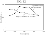
- FIG. 12 shows changes in echo height relative to the distance at a time when the flaw 101 is present on the back side of the steel sheet 100.
- the echo height of the S1 mode generated at an angle of incidence of 24.6° gradually decreases with the distance
- the echo height of the AOSO mode generated at an angle of incidence of 34.5° exhibits a complex characteristic in which the echo height increases and then decreases.
- FIG. 13 shows results of sound field simulation (a distance of 300 mm) obtained when the AOSO mode is propagated at an angle of incidence of 34.5°.
- FIG. 13 from 10 ⁇ s to 30 ⁇ s sound fields near the ultrasonic probe 1 are shown, and from 90 ⁇ s to 110 ⁇ s sound fields near the flaw 101 are shown.
- energy of the plate wave is concentrated on the front side of the steel sheet 100.
- the energy distribution changes little by little with propagation, and when the plate wave reaches the flaw 101 present at a location with a distance of 300 mm, the energy of the plate wave is concentrated on the back side of the steel sheet 100.
- FIG. 14 shows a simulated representation of a transition of the energy distribution of the AOSO mode.
- the energy of the plate wave becomes stronger on the front side of the steel sheet 100.
- a state in which the energy becomes stronger on the back side is obtained.
- the plate wave propagates in such a manner that after going through a state in which the front and back sides have a comparable energy distribution again, the energy becomes stronger on the front side.
- the AOSO mode has the characteristics shown in FIGS. 9 and 12 .
- FIG. 15 shows results of sound field simulation (a distance of 300 mm) obtained when the S1 mode is propagated at an angle of incidence of 24.6°.
- FIG. 15 shows results of sound field simulation (a distance of 300 mm) obtained when the S1 mode is propagated at an angle of incidence of 24.6°.
- FIG. 15 shows from 10 ⁇ s to 30 ⁇ s sound fields near the ultrasonic probe 1 are shown, and from 120 ⁇ s to 140 ⁇ s sound fields near the flaw 101 are shown.
- a sound field distribution hardly changes, and is substantially uniform in a plate thickness direction.
- FIG. 16 shows a simulated representation of a transition of an energy distribution of the S1 mode.
- the energy distribution hardly changes. Since the energy distribution is substantially uniform in the plate thickness direction, changes in echo height relative to the distance are almost the same between in a case where the flaw 101 is present on the front side of the steel sheet 100 and in a case where the flaw 101 is present on the back side of the steel sheet 100.
- the S1 mode has the characteristics shown in FIGS. 9 and 12 .
- FIG. 17 is a flowchart showing the operation of the transmission signal processing unit 3a
- FIG. 18 is a flowchart showing the operation of the reception signal processing unit 3b.
- the transmission signal processing unit 3a transmits delay signals for the respective arrayed transducer elements of the transducer 1b to the transmitting unit 4 so as to obtain the angle of incidence at which the AOSO mode propagates (step ST11).
- the transmitting unit 4 generates excitation signals using the delay signals transmitted from the transmission signal processing unit 3a, to excite the respective arrayed transducer elements of the transducer 1b in the ultrasonic probe 1.
- An example of FIG. 2 shows the state of propagation of ultrasound in the wedge 1a in a case in which a delay time assigned to the arrayed leftmost element of the transducer 1b is long and a delay time assigned to the rightmost element is short. Note that the angle of incidence at which the AOSO mode propagates changes depending on the thickness of the steel sheet 100, the sound velocity of the wedge 1a, and the frequency, and thus is not limited to the angle (34.5°) shown in the simulation.
- each of the arrayed transducer elements of the transducer 1b in the ultrasonic probe 1 receives, as an echo, the corresponding plate wave reflected by the flaw 101, converts the echo into an electrical signal, and transmits the electrical signal to the receiving unit 5.
- the receiving unit 5 amplifies the echo as necessary, and transmits the echo to the signal processing unit 3.
- the reception signal processing unit 3b assigns a delay time corresponding to each of the arrayed transducer elements of the transducer 1b to the corresponding echo, and combines the echo of each of the transducer elements.
- the amplitude of the echo is determined as E1 and the reception time of the echo is determined as T1, and the values of the E1 and T1 are stored in the RAM 303 or the storage 304 that is included in the reception signal processing unit 3b (step ST21).
- plate waves in AOSO mode are allowed to propagate through the steel sheet 100 by controlling the angle of incidence and the angle at which reception is performed in a phased array system, by which the transmission and reception are performed.
- the angle of incidence is changed in the phased array system, to generate plate waves in S1 mode in the steel sheet 100.
- the transmission signal processing unit 3a transmits delay signals for the respective arrayed transducer elements of the transducer 1b to the transmitting unit 4 so as to obtain the angle of incidence at which the S1 mode propagates (step ST12).
- the angle of incidence at which the S1 mode propagates changes depending on the thickness of the steel sheet 100, the sound velocity of the wedge 1a, and the frequency, and thus is not limited to the angle (24.6°) shown in the simulation.
- each of the arrayed transducer elements of the transducer 1b in the ultrasonic probe 1 receives, as an echo, the corresponding plate wave reflected by the flaw 101, converts the echo into an electrical signal, and transmits the electrical signal to the receiving unit 5.
- the receiving unit 5 amplifies the echo as necessary, and transmits the echo to the signal processing unit 3.
- the reception signal processing unit 3b determines the amplitude E2 and reception time T2 of the echo in S 1 mode in the phased array system, and stores the amplitude E2 and the reception time T2 in the RAM 303 or the storage 304 that is included in the reception signal processing unit 3b (step ST22).
- the group velocity of a plate wave is also determined. Namely, it is possible to estimate, from a reception time of an echo, a distance from the ultrasonic probe 1 to the flaw 101.
- the group velocity of the AOSO mode is substantially 3000 m/s regardless of the frequency, and thus, from T1 ⁇ 3000 m/s, a back-and-forth propagation distance of the AOSO mode can be determined.
- the reception signal processing unit 3b determines a distance from the ultrasonic probe 1 to the flaw 101, and sets the distance as L (step ST23).
- the reception signal processing unit 3b compares the amplitude E1 of the AOSO mode with the amplitude E2 of the S 1 mode, and determines, from characteristics of the echo height relative to the distance, on which one of the front and back sides of the steel sheet 100 the flaw 101 is present (step ST24). For example, if the characteristics of the echo height relative to the distance are the same as those of FIGS. 9 and 12 , then when the value of the distance L is 300 mm, the following relationships are evident:
- the reception signal processing unit 3b displays the determination result on the display 307.
- the ultrasonic probe 1 may send out ultrasound to the steel sheet 100 at a plurality of angles by mechanically scanning.
- a plurality of angles may be obtained by using a type of variable angle probe as the ultrasonic probe 1.
- a plurality of angles may be obtained by using a plurality of angle probes having different angles of incidence.
- the angle probe does not need to be used as long as an ultrasonic probe that allows ultrasound to obliquely enter the steel sheet 100 is used.
- an ultrasonic flaw detection device of the first embodiment includes: an ultrasonic probe that generates ultrasound waves corresponding to transmission signals to be provided thereto, and sends out the ultrasound waves into a specimen, and receives echoes of the respective ultrasound waves having propagated through the specimen, and outputs the received echoes as reception signals; a transmission signal processing unit that generates, as the transmission signals, signals that are used by the ultrasonic probe to send out the ultrasound waves to the specimen obliquely at a respective plurality of angles; and a reception signal processing unit that determines, from the reception signals, amplitudes of the echoes corresponding to the plurality of angles, and periods of time from when the respective ultrasound waves are sent out until the respective echoes are received, as reception times, and identifies a location of an acoustic discontinuous portion in the specimen from the reception times and a ratio between the amplitudes, and thus, there is an advantageous effect of being able to determine on which one of the front and back sides of the specimen a flaw is
- a transducer of the ultrasonic probe includes a plurality of arrayed transducer elements, and the transmission signal processing unit generates a set of signals having different delay times corresponding to the respective plurality of transducer elements, as a signal corresponding to each of the plurality of angles, and thus, a configuration for sending out ultrasound waves at the plurality of angles can be easily implemented.
- the ultrasonic probe sends out the ultrasound waves to the specimen obliquely at the respective plurality of angles by mechanically scanning, and thus, as the ultrasonic probe, various probes can be selected.
- an ultrasonic flaw detection device relates to a configuration in which plate waves in a plurality of different modes are allowed to propagate through a specimen using an ultrasonic probe, and the properties of the specimen are determined from the amplitude ratio and amounts of receive time of a plurality of received echoes, and is suitable for detecting a flaw, including determining on which one of the front and back of a steel sheet the flaw is present.
Landscapes
- Physics & Mathematics (AREA)
- General Physics & Mathematics (AREA)
- Chemical & Material Sciences (AREA)
- Life Sciences & Earth Sciences (AREA)
- Health & Medical Sciences (AREA)
- Analytical Chemistry (AREA)
- Biochemistry (AREA)
- General Health & Medical Sciences (AREA)
- Immunology (AREA)
- Pathology (AREA)
- Acoustics & Sound (AREA)
- Engineering & Computer Science (AREA)
- Signal Processing (AREA)
- Algebra (AREA)
- Mathematical Analysis (AREA)
- Mathematical Optimization (AREA)
- Mathematical Physics (AREA)
- Pure & Applied Mathematics (AREA)
- Investigating Or Analyzing Materials By The Use Of Ultrasonic Waves (AREA)
Applications Claiming Priority (1)
| Application Number | Priority Date | Filing Date | Title |
|---|---|---|---|
| PCT/JP2017/044038 WO2019111381A1 (ja) | 2017-12-07 | 2017-12-07 | 超音波探傷装置 |
Publications (3)
| Publication Number | Publication Date |
|---|---|
| EP3722801A1 EP3722801A1 (en) | 2020-10-14 |
| EP3722801A4 EP3722801A4 (en) | 2020-11-25 |
| EP3722801B1 true EP3722801B1 (en) | 2024-10-23 |
Family
ID=66750212
Family Applications (1)
| Application Number | Title | Priority Date | Filing Date |
|---|---|---|---|
| EP17933982.5A Active EP3722801B1 (en) | 2017-12-07 | 2017-12-07 | Ultrasonic flaw detection method |
Country Status (4)
| Country | Link |
|---|---|
| US (1) | US11307174B2 (ja) |
| EP (1) | EP3722801B1 (ja) |
| JP (1) | JP6671565B2 (ja) |
| WO (1) | WO2019111381A1 (ja) |
Families Citing this family (5)
| Publication number | Priority date | Publication date | Assignee | Title |
|---|---|---|---|---|
| JP7236893B2 (ja) * | 2019-03-20 | 2023-03-10 | 三菱電機株式会社 | 液体検知方法および液体検知装置 |
| US11143625B2 (en) * | 2019-11-14 | 2021-10-12 | The Boeing Company | Ultrasonic inspection of parts |
| US11578971B2 (en) | 2021-02-12 | 2023-02-14 | Holloway Ndt & Engineering Inc. | Ultrasonic testing using a phased array |
| EP4323723A4 (en) | 2021-04-15 | 2025-05-28 | Oscps Motion Sensing Inc. | OPTICAL GYROSCOPES AND METHODS FOR MANUFACTURING OPTICAL GYROSCOPES |
| CN117538411B (zh) * | 2023-10-11 | 2025-10-31 | 闽江学院 | 一种槟榔芋变质检测方法、系统、设备和介质 |
Family Cites Families (17)
| Publication number | Priority date | Publication date | Assignee | Title |
|---|---|---|---|---|
| US4294118A (en) * | 1979-10-29 | 1981-10-13 | Sumitomo Kinzoku Kogyo Kabushiki Kaisha | Fully automatic ultrasonic flaw detection apparatus |
| US4435984A (en) * | 1980-04-21 | 1984-03-13 | Southwest Research Institute | Ultrasonic multiple-beam technique for detecting cracks in bimetallic or coarse-grained materials |
| US4570487A (en) * | 1980-04-21 | 1986-02-18 | Southwest Research Institute | Multibeam satellite-pulse observation technique for characterizing cracks in bimetallic coarse-grained component |
| US4497210A (en) | 1982-07-05 | 1985-02-05 | Tokyo Shibaura Denki Kabushiki Kaisha | Phased array ultrasonic testing apparatus and testing method therefor |
| JPS62261955A (ja) * | 1986-05-09 | 1987-11-14 | Toshiba Corp | 超音波探傷装置 |
| DE3715914A1 (de) * | 1987-05-13 | 1988-12-01 | Fraunhofer Ges Forschung | Verfahren und vorrichtung zum nachweis von rissen mit hilfe von ultraschall |
| WO1991002971A1 (fr) * | 1989-08-21 | 1991-03-07 | Hitachi Construction Machinery Co., Ltd. | Detecteur ultrasonique de defauts |
| DE9214948U1 (de) | 1992-11-03 | 1994-03-10 | Siemens AG, 80333 München | Ultraschallwandler-Anordnung |
| JPH06331603A (ja) | 1993-05-18 | 1994-12-02 | Nippon Steel Corp | 鋼板表面疵探傷方法 |
| EP0829714A4 (en) * | 1996-03-28 | 2007-06-27 | Mitsubishi Electric Corp | ULTRASONIC SOUND DETECTOR AND ULTRASONIC PROCEDURE FOR DETECTING ERRORS |
| DE19627957A1 (de) * | 1996-07-11 | 1998-01-15 | Bbc Reaktor Gmbh | Ultraschallwinkelprüfkopf und Verfahren zum Betreiben des Winkelprüfkopfes |
| US5814731A (en) * | 1997-01-28 | 1998-09-29 | Alexander; Alton Michel | Ultrasonic scanning apparatus for nondestructive site characterization of structures using a planar based acoustic transmitter and receiver in a rolling pond |
| JP4552309B2 (ja) * | 2000-11-02 | 2010-09-29 | 株式会社Ihi | 超音波探傷方法及び装置 |
| US7093490B2 (en) * | 2004-02-23 | 2006-08-22 | Hitachi, Ltd. | Ultrasonic flaw detecting method and ultrasonic flaw detector |
| JP5800667B2 (ja) * | 2011-10-17 | 2015-10-28 | 日立Geニュークリア・エナジー株式会社 | 超音波検査方法,超音波探傷方法及び超音波検査装置 |
| JP2013156166A (ja) * | 2012-01-30 | 2013-08-15 | Mitsubishi Heavy Ind Ltd | 超音波探傷方法 |
| JP2013242202A (ja) * | 2012-05-18 | 2013-12-05 | Hitachi-Ge Nuclear Energy Ltd | 超音波検査方法及び超音波検査装置 |
-
2017
- 2017-12-07 EP EP17933982.5A patent/EP3722801B1/en active Active
- 2017-12-07 US US16/757,685 patent/US11307174B2/en active Active
- 2017-12-07 WO PCT/JP2017/044038 patent/WO2019111381A1/ja not_active Ceased
- 2017-12-07 JP JP2019557948A patent/JP6671565B2/ja active Active
Also Published As
| Publication number | Publication date |
|---|---|
| JP6671565B2 (ja) | 2020-03-25 |
| WO2019111381A1 (ja) | 2019-06-13 |
| EP3722801A1 (en) | 2020-10-14 |
| US11307174B2 (en) | 2022-04-19 |
| US20200249205A1 (en) | 2020-08-06 |
| JPWO2019111381A1 (ja) | 2020-04-02 |
| EP3722801A4 (en) | 2020-11-25 |
Similar Documents
| Publication | Publication Date | Title |
|---|---|---|
| EP3722801B1 (en) | Ultrasonic flaw detection method | |
| Ying et al. | Multi-mode laser-ultrasound imaging using Time-domain Synthetic Aperture Focusing Technique (T-SAFT) | |
| JP4776707B2 (ja) | 超音波画像化装置 | |
| KR101225244B1 (ko) | 자동 빔 집속 장치 및 이를 이용한 비파괴 검사 방법 | |
| JP2008209364A (ja) | 管体の超音波探傷装置および超音波探傷方法 | |
| US9488623B2 (en) | Guided wave mode sweep technique for optimal mode and frequency excitation | |
| CA3110818A1 (en) | Continuous wave ultrasound or acoustic non-destructive testing | |
| CN104605890A (zh) | 一种剪切波峰值波形校正的方法、装置、系统及其应用 | |
| EP3985388A1 (en) | Ultrasound flaw detection method, ultrasound flaw detection device, manufacturing equipment line for steel material, manufacturing method for steel material, and quality assurance method for steel material | |
| JP4166222B2 (ja) | 超音波探傷方法及び装置 | |
| JP2010266416A (ja) | フェーズドアレイ開口合成処理方法並びにその適用効果評価方法 | |
| US20110126628A1 (en) | Non-destructive ultrasound inspection with coupling check | |
| KR101826917B1 (ko) | 다중 채널 초음파를 이용한 장거리 배관 진단 방법 | |
| Han et al. | Application of ultrasonic phased array total focusing method in weld inspection using an inclined wedge | |
| JP3635453B2 (ja) | 超音波横波斜角探傷方法及び装置 | |
| JP2014077708A (ja) | 検査装置および検査方法 | |
| CN108369214A (zh) | 超声波检测物体的方法 | |
| JP2006234701A (ja) | 超音波探傷装置及び超音波探傷装置方法 | |
| JP5567472B2 (ja) | 超音波検査方法及び超音波検査装置 | |
| JP2012054843A (ja) | 空気超音波センサー及び空気超音波センサーの整合層の形状決定方法 | |
| JP2006162614A (ja) | 超音波プローブ並びに検査方法及びシステム | |
| EP2354808B1 (en) | Object probing device, object probing program, and object probing method | |
| JP4270040B2 (ja) | 超音波探傷方法 | |
| Stepinski et al. | Designing 2D arrays for SHM of planar structures: a review | |
| JP5428249B2 (ja) | 管体の肉厚形状測定装置、その方法および管体の製造方法 |
Legal Events
| Date | Code | Title | Description |
|---|---|---|---|
| STAA | Information on the status of an ep patent application or granted ep patent |
Free format text: STATUS: THE INTERNATIONAL PUBLICATION HAS BEEN MADE |
|
| PUAI | Public reference made under article 153(3) epc to a published international application that has entered the european phase |
Free format text: ORIGINAL CODE: 0009012 |
|
| STAA | Information on the status of an ep patent application or granted ep patent |
Free format text: STATUS: REQUEST FOR EXAMINATION WAS MADE |
|
| 17P | Request for examination filed |
Effective date: 20200529 |
|
| AK | Designated contracting states |
Kind code of ref document: A1 Designated state(s): AL AT BE BG CH CY CZ DE DK EE ES FI FR GB GR HR HU IE IS IT LI LT LU LV MC MK MT NL NO PL PT RO RS SE SI SK SM TR |
|
| AX | Request for extension of the european patent |
Extension state: BA ME |
|
| A4 | Supplementary search report drawn up and despatched |
Effective date: 20201022 |
|
| RIC1 | Information provided on ipc code assigned before grant |
Ipc: G01N 29/48 20060101ALI20201016BHEP Ipc: G01N 29/11 20060101AFI20201016BHEP Ipc: G01N 29/04 20060101ALI20201016BHEP Ipc: G01N 29/24 20060101ALI20201016BHEP Ipc: G01N 29/44 20060101ALI20201016BHEP Ipc: G01N 29/22 20060101ALI20201016BHEP |
|
| DAV | Request for validation of the european patent (deleted) | ||
| DAX | Request for extension of the european patent (deleted) | ||
| STAA | Information on the status of an ep patent application or granted ep patent |
Free format text: STATUS: EXAMINATION IS IN PROGRESS |
|
| 17Q | First examination report despatched |
Effective date: 20221107 |
|
| REG | Reference to a national code |
Ref legal event code: R079 Ref country code: DE Ref document number: 602017085727 Country of ref document: DE Free format text: PREVIOUS MAIN CLASS: G01N0029110000 Ipc: G01N0029060000 |
|
| GRAP | Despatch of communication of intention to grant a patent |
Free format text: ORIGINAL CODE: EPIDOSNIGR1 |
|
| GRAP | Despatch of communication of intention to grant a patent |
Free format text: ORIGINAL CODE: EPIDOSNIGR1 |
|
| STAA | Information on the status of an ep patent application or granted ep patent |
Free format text: STATUS: GRANT OF PATENT IS INTENDED |
|
| RIC1 | Information provided on ipc code assigned before grant |
Ipc: G01N 29/48 20060101ALI20240528BHEP Ipc: G01N 29/44 20060101ALI20240528BHEP Ipc: G01N 29/24 20060101ALI20240528BHEP Ipc: G01N 29/22 20060101ALI20240528BHEP Ipc: G01N 29/04 20060101ALI20240528BHEP Ipc: G01N 29/26 20060101ALI20240528BHEP Ipc: G01N 29/11 20060101ALI20240528BHEP Ipc: G01N 29/07 20060101ALI20240528BHEP Ipc: G01N 29/06 20060101AFI20240528BHEP |
|
| INTG | Intention to grant announced |
Effective date: 20240614 |
|
| GRAS | Grant fee paid |
Free format text: ORIGINAL CODE: EPIDOSNIGR3 |
|
| GRAA | (expected) grant |
Free format text: ORIGINAL CODE: 0009210 |
|
| STAA | Information on the status of an ep patent application or granted ep patent |
Free format text: STATUS: THE PATENT HAS BEEN GRANTED |
|
| AK | Designated contracting states |
Kind code of ref document: B1 Designated state(s): AL AT BE BG CH CY CZ DE DK EE ES FI FR GB GR HR HU IE IS IT LI LT LU LV MC MK MT NL NO PL PT RO RS SE SI SK SM TR |
|
| REG | Reference to a national code |
Ref country code: GB Ref legal event code: FG4D |
|
| REG | Reference to a national code |
Ref country code: CH Ref legal event code: EP |
|
| REG | Reference to a national code |
Ref country code: DE Ref legal event code: R096 Ref document number: 602017085727 Country of ref document: DE |
|
| REG | Reference to a national code |
Ref country code: IE Ref legal event code: FG4D |
|
| REG | Reference to a national code |
Ref country code: LT Ref legal event code: MG9D |
|
| REG | Reference to a national code |
Ref country code: NL Ref legal event code: MP Effective date: 20241023 |
|
| REG | Reference to a national code |
Ref country code: AT Ref legal event code: MK05 Ref document number: 1735229 Country of ref document: AT Kind code of ref document: T Effective date: 20241023 |
|
| PG25 | Lapsed in a contracting state [announced via postgrant information from national office to epo] |
Ref country code: NL Free format text: LAPSE BECAUSE OF FAILURE TO SUBMIT A TRANSLATION OF THE DESCRIPTION OR TO PAY THE FEE WITHIN THE PRESCRIBED TIME-LIMIT Effective date: 20241023 |
|
| PG25 | Lapsed in a contracting state [announced via postgrant information from national office to epo] |
Ref country code: NL Free format text: LAPSE BECAUSE OF FAILURE TO SUBMIT A TRANSLATION OF THE DESCRIPTION OR TO PAY THE FEE WITHIN THE PRESCRIBED TIME-LIMIT Effective date: 20241023 |
|
| PG25 | Lapsed in a contracting state [announced via postgrant information from national office to epo] |
Ref country code: PT Free format text: LAPSE BECAUSE OF FAILURE TO SUBMIT A TRANSLATION OF THE DESCRIPTION OR TO PAY THE FEE WITHIN THE PRESCRIBED TIME-LIMIT Effective date: 20250224 Ref country code: HR Free format text: LAPSE BECAUSE OF FAILURE TO SUBMIT A TRANSLATION OF THE DESCRIPTION OR TO PAY THE FEE WITHIN THE PRESCRIBED TIME-LIMIT Effective date: 20241023 Ref country code: IS Free format text: LAPSE BECAUSE OF FAILURE TO SUBMIT A TRANSLATION OF THE DESCRIPTION OR TO PAY THE FEE WITHIN THE PRESCRIBED TIME-LIMIT Effective date: 20250223 |
|
| PG25 | Lapsed in a contracting state [announced via postgrant information from national office to epo] |
Ref country code: FI Free format text: LAPSE BECAUSE OF FAILURE TO SUBMIT A TRANSLATION OF THE DESCRIPTION OR TO PAY THE FEE WITHIN THE PRESCRIBED TIME-LIMIT Effective date: 20241023 |
|
| PG25 | Lapsed in a contracting state [announced via postgrant information from national office to epo] |
Ref country code: BG Free format text: LAPSE BECAUSE OF FAILURE TO SUBMIT A TRANSLATION OF THE DESCRIPTION OR TO PAY THE FEE WITHIN THE PRESCRIBED TIME-LIMIT Effective date: 20241023 |
|
| PG25 | Lapsed in a contracting state [announced via postgrant information from national office to epo] |
Ref country code: ES Free format text: LAPSE BECAUSE OF FAILURE TO SUBMIT A TRANSLATION OF THE DESCRIPTION OR TO PAY THE FEE WITHIN THE PRESCRIBED TIME-LIMIT Effective date: 20241023 |
|
| PG25 | Lapsed in a contracting state [announced via postgrant information from national office to epo] |
Ref country code: NO Free format text: LAPSE BECAUSE OF FAILURE TO SUBMIT A TRANSLATION OF THE DESCRIPTION OR TO PAY THE FEE WITHIN THE PRESCRIBED TIME-LIMIT Effective date: 20250123 |
|
| PG25 | Lapsed in a contracting state [announced via postgrant information from national office to epo] |
Ref country code: AT Free format text: LAPSE BECAUSE OF FAILURE TO SUBMIT A TRANSLATION OF THE DESCRIPTION OR TO PAY THE FEE WITHIN THE PRESCRIBED TIME-LIMIT Effective date: 20241023 Ref country code: LV Free format text: LAPSE BECAUSE OF FAILURE TO SUBMIT A TRANSLATION OF THE DESCRIPTION OR TO PAY THE FEE WITHIN THE PRESCRIBED TIME-LIMIT Effective date: 20241023 Ref country code: GR Free format text: LAPSE BECAUSE OF FAILURE TO SUBMIT A TRANSLATION OF THE DESCRIPTION OR TO PAY THE FEE WITHIN THE PRESCRIBED TIME-LIMIT Effective date: 20250124 |
|
| PG25 | Lapsed in a contracting state [announced via postgrant information from national office to epo] |
Ref country code: PL Free format text: LAPSE BECAUSE OF FAILURE TO SUBMIT A TRANSLATION OF THE DESCRIPTION OR TO PAY THE FEE WITHIN THE PRESCRIBED TIME-LIMIT Effective date: 20241023 |
|
| PG25 | Lapsed in a contracting state [announced via postgrant information from national office to epo] |
Ref country code: RS Free format text: LAPSE BECAUSE OF FAILURE TO SUBMIT A TRANSLATION OF THE DESCRIPTION OR TO PAY THE FEE WITHIN THE PRESCRIBED TIME-LIMIT Effective date: 20250123 |
|
| PG25 | Lapsed in a contracting state [announced via postgrant information from national office to epo] |
Ref country code: SM Free format text: LAPSE BECAUSE OF FAILURE TO SUBMIT A TRANSLATION OF THE DESCRIPTION OR TO PAY THE FEE WITHIN THE PRESCRIBED TIME-LIMIT Effective date: 20241023 |
|
| PG25 | Lapsed in a contracting state [announced via postgrant information from national office to epo] |
Ref country code: MC Free format text: LAPSE BECAUSE OF FAILURE TO SUBMIT A TRANSLATION OF THE DESCRIPTION OR TO PAY THE FEE WITHIN THE PRESCRIBED TIME-LIMIT Effective date: 20241023 |
|
| PG25 | Lapsed in a contracting state [announced via postgrant information from national office to epo] |
Ref country code: DK Free format text: LAPSE BECAUSE OF FAILURE TO SUBMIT A TRANSLATION OF THE DESCRIPTION OR TO PAY THE FEE WITHIN THE PRESCRIBED TIME-LIMIT Effective date: 20241023 |
|
| PG25 | Lapsed in a contracting state [announced via postgrant information from national office to epo] |
Ref country code: EE Free format text: LAPSE BECAUSE OF FAILURE TO SUBMIT A TRANSLATION OF THE DESCRIPTION OR TO PAY THE FEE WITHIN THE PRESCRIBED TIME-LIMIT Effective date: 20241023 |
|
| PG25 | Lapsed in a contracting state [announced via postgrant information from national office to epo] |
Ref country code: RO Free format text: LAPSE BECAUSE OF FAILURE TO SUBMIT A TRANSLATION OF THE DESCRIPTION OR TO PAY THE FEE WITHIN THE PRESCRIBED TIME-LIMIT Effective date: 20241023 |
|
| REG | Reference to a national code |
Ref country code: DE Ref legal event code: R097 Ref document number: 602017085727 Country of ref document: DE |
|
| PG25 | Lapsed in a contracting state [announced via postgrant information from national office to epo] |
Ref country code: SK Free format text: LAPSE BECAUSE OF FAILURE TO SUBMIT A TRANSLATION OF THE DESCRIPTION OR TO PAY THE FEE WITHIN THE PRESCRIBED TIME-LIMIT Effective date: 20241023 |
|
| PG25 | Lapsed in a contracting state [announced via postgrant information from national office to epo] |
Ref country code: CZ Free format text: LAPSE BECAUSE OF FAILURE TO SUBMIT A TRANSLATION OF THE DESCRIPTION OR TO PAY THE FEE WITHIN THE PRESCRIBED TIME-LIMIT Effective date: 20241023 |
|
| PG25 | Lapsed in a contracting state [announced via postgrant information from national office to epo] |
Ref country code: IT Free format text: LAPSE BECAUSE OF FAILURE TO SUBMIT A TRANSLATION OF THE DESCRIPTION OR TO PAY THE FEE WITHIN THE PRESCRIBED TIME-LIMIT Effective date: 20241023 |
|
| REG | Reference to a national code |
Ref country code: CH Ref legal event code: PL |
|
| PG25 | Lapsed in a contracting state [announced via postgrant information from national office to epo] |
Ref country code: LU Free format text: LAPSE BECAUSE OF NON-PAYMENT OF DUE FEES Effective date: 20241207 |
|
| PLBE | No opposition filed within time limit |
Free format text: ORIGINAL CODE: 0009261 |
|
| STAA | Information on the status of an ep patent application or granted ep patent |
Free format text: STATUS: NO OPPOSITION FILED WITHIN TIME LIMIT |
|
| PG25 | Lapsed in a contracting state [announced via postgrant information from national office to epo] |
Ref country code: SE Free format text: LAPSE BECAUSE OF FAILURE TO SUBMIT A TRANSLATION OF THE DESCRIPTION OR TO PAY THE FEE WITHIN THE PRESCRIBED TIME-LIMIT Effective date: 20241023 |
|
| GBPC | Gb: european patent ceased through non-payment of renewal fee |
Effective date: 20250123 |
|
| 26N | No opposition filed |
Effective date: 20250724 |
|
| P01 | Opt-out of the competence of the unified patent court (upc) registered |
Free format text: CASE NUMBER: UPC_APP_4903_3722801/2025 Effective date: 20250827 |
|
| REG | Reference to a national code |
Ref country code: BE Ref legal event code: MM Effective date: 20241231 |
|
| PG25 | Lapsed in a contracting state [announced via postgrant information from national office to epo] |
Ref country code: GB Free format text: LAPSE BECAUSE OF NON-PAYMENT OF DUE FEES Effective date: 20250123 Ref country code: BE Free format text: LAPSE BECAUSE OF NON-PAYMENT OF DUE FEES Effective date: 20241231 |
|
| PG25 | Lapsed in a contracting state [announced via postgrant information from national office to epo] |
Ref country code: CH Free format text: LAPSE BECAUSE OF NON-PAYMENT OF DUE FEES Effective date: 20241231 |
|
| PG25 | Lapsed in a contracting state [announced via postgrant information from national office to epo] |
Ref country code: IE Free format text: LAPSE BECAUSE OF NON-PAYMENT OF DUE FEES Effective date: 20241207 |
|
| PGFP | Annual fee paid to national office [announced via postgrant information from national office to epo] |
Ref country code: DE Payment date: 20251028 Year of fee payment: 9 |
|
| PGFP | Annual fee paid to national office [announced via postgrant information from national office to epo] |
Ref country code: FR Payment date: 20251117 Year of fee payment: 9 |
|
| PG25 | Lapsed in a contracting state [announced via postgrant information from national office to epo] |
Ref country code: CY Free format text: LAPSE BECAUSE OF FAILURE TO SUBMIT A TRANSLATION OF THE DESCRIPTION OR TO PAY THE FEE WITHIN THE PRESCRIBED TIME-LIMIT; INVALID AB INITIO Effective date: 20171207 |