EP3723268B1 - Interface intégrée au composant - Google Patents
Interface intégrée au composant Download PDFInfo
- Publication number
- EP3723268B1 EP3723268B1 EP20163658.6A EP20163658A EP3723268B1 EP 3723268 B1 EP3723268 B1 EP 3723268B1 EP 20163658 A EP20163658 A EP 20163658A EP 3723268 B1 EP3723268 B1 EP 3723268B1
- Authority
- EP
- European Patent Office
- Prior art keywords
- electronics
- motor
- control
- interface
- commutation
- Prior art date
- Legal status (The legal status is an assumption and is not a legal conclusion. Google has not performed a legal analysis and makes no representation as to the accuracy of the status listed.)
- Active
Links
Images
Classifications
-
- H—ELECTRICITY
- H02—GENERATION; CONVERSION OR DISTRIBUTION OF ELECTRIC POWER
- H02P—CONTROL OR REGULATION OF ELECTRIC MOTORS, ELECTRIC GENERATORS OR DYNAMO-ELECTRIC CONVERTERS; CONTROLLING TRANSFORMERS, REACTORS OR CHOKE COILS
- H02P6/00—Arrangements for controlling synchronous motors or other dynamo-electric motors using electronic commutation dependent on the rotor position; Electronic commutators therefor
- H02P6/08—Arrangements for controlling the speed or torque of a single motor
-
- H—ELECTRICITY
- H02—GENERATION; CONVERSION OR DISTRIBUTION OF ELECTRIC POWER
- H02K—DYNAMO-ELECTRIC MACHINES
- H02K11/00—Structural association of dynamo-electric machines with electric components or with devices for shielding, monitoring or protection
- H02K11/30—Structural association with control circuits or drive circuits
-
- H—ELECTRICITY
- H02—GENERATION; CONVERSION OR DISTRIBUTION OF ELECTRIC POWER
- H02K—DYNAMO-ELECTRIC MACHINES
- H02K11/00—Structural association of dynamo-electric machines with electric components or with devices for shielding, monitoring or protection
- H02K11/40—Structural association with grounding devices
-
- H—ELECTRICITY
- H02—GENERATION; CONVERSION OR DISTRIBUTION OF ELECTRIC POWER
- H02P—CONTROL OR REGULATION OF ELECTRIC MOTORS, ELECTRIC GENERATORS OR DYNAMO-ELECTRIC CONVERTERS; CONTROLLING TRANSFORMERS, REACTORS OR CHOKE COILS
- H02P6/00—Arrangements for controlling synchronous motors or other dynamo-electric motors using electronic commutation dependent on the rotor position; Electronic commutators therefor
- H02P6/14—Electronic commutators
- H02P6/16—Circuit arrangements for detecting position
- H02P6/17—Circuit arrangements for detecting position and for generating speed information
-
- G—PHYSICS
- G08—SIGNALLING
- G08C—TRANSMISSION SYSTEMS FOR MEASURED VALUES, CONTROL OR SIMILAR SIGNALS
- G08C19/00—Electric signal transmission systems
Definitions
- the invention relates to an interface of a commutation electronics for controlling direct current motors, in particular direct current motors of fans.
- Speed-controlled brushless DC motors are used in a variety of ways in industry, for example in variable speed combustion air fans for modern gas heaters. These fans are often controlled by control electronics via a standardized PWM interface, in which the control electronics generate a PWM signal that usually corresponds to the desired motor power of the fan, e.g. a PWM signal with a duty cycle of 10% means a motor power of 10% of the maximum engine power.
- the required duty cycle can be controlled by the control electronics according to the requirements.
- the control electronics of a device are connected via an interface to the commutation electronics for commutation of the EC motor.
- a galvanic separation is usually provided between the control electronics and the commutation electronics.
- the galvanic separation can be arranged on the input side in the interface area of the commutation electronics. After such a galvanic separation, the PWM signal is recorded by electronics integrated in the EC motor and converted by the motor commutation electronics via a driver module into a control signal for the motor winding.
- a certain speed is set for the received signal, which is usually measured by a Hall sensor and transmitted to the control unit via a (further) galvanic isolation.
- the control unit evaluates this speed information, which is received from the Hall sensors of the commutation electronics, and adjusts the PWM signal if there is a deviation from the target value.
- the motor manufacturers provide the commutation electronics on the motor side with an interface for the control electronics.
- the control electronics are provided by the customer. or from a third party, but usually not from the motor manufacturer.
- the manufacturer of a boiler control system provides the control for the commutation electronics of the motor of a fan that is used in the boiler. This creates an interface between the commutation electronics on the motor side and the user-side control electronics. If, for example, the setpoint signal for the fan is specified as a PWM signal depending on the boiler type, the motor manufacturer must convert this into a corresponding speed.
- the commutation electronics are located on the motor, the corresponding electronic components on the motor control side are different for different required motor powers, but the control electronics (i.e. customer side), such as a boiler control, remain fundamentally the same, since the target speed is specified as a PWM signal.
- a further disadvantage is that when designed with commutation electronics integrated into the motor, the connection cables for the mains voltage and control signals, due to their weight and rigidity, place a load on the vibration dampers of the motor and influence the vibration characteristics.
- control electronics then have to transmit fast switching signals to the motor, which can emit interference over the length of the cable, particularly in the case of long cables, and in turn require extensive and costly interference suppression and EMC protection measures.
- control electronics would have to be adapted to the respective motor: e.g. to the electrical power consumption of the motor. This creates a high degree of variance in the application-side control units, which is undesirable and expensive.
- EP 2 528 228 A2 a device for controlling an electric motor in a motor vehicle by means of an electronic control unit.
- the device comprises the control unit, a first line via which electrical energy is applied to a control circuit of the motor, and a second line via which the control circuit is connected to ground, and wherein the device has means for transmitting a control signal with information regarding a desired speed of the electric motor from the control unit to the control circuit and means for transmitting a functional status signal with information regarding a function of the electric motor from the control circuit to the control unit.
- the means for transmitting the control signal and the means for transmitting the functional status signal are designed as a common line. Further motor controls are known from EN 10 2016 119826 A1 and WO 2004/114513 A1 known. 1
- the invention is therefore based on the object of overcoming the aforementioned disadvantages and providing an optimized and improved PWM interface between control electronics and commutation electronics of an EC motor, which nevertheless allows a high degree of flexibility.
- a basic idea of the invention is a PWM interface between the control unit and engine electronics in which in particular the galvanic isolation between the control unit and engine electronics is arranged in such a way that only three connecting lines of the interface are required. It is particularly advantageous if these are only at a common voltage potential compared to a reference potential.
- the connecting lines of the interface for the voltage supply and for the transmission of a PWM signal are designed such that one of the three connecting lines is designed as a bi-directional communication line in order to transmit a PWM signal for the speed control of the EC motor to the commutation electronics.
- Slow signals in the sense of the present invention are those signals which are at least a factor of 8, preferably a factor of 10, below the transmission speed of the PWM signals (e.g. setpoint signals 2 kHz and PWM signals 200 kHz).
- control electronics only the control electronics have a mains voltage connection, while the motor control is supplied with the required voltage via the interface.
- control electronics provide a rectified voltage, preferably filtered and sieved direct current, for the motor electronics via a rectifier.
- the interface provides two connections for the reference potential and the direct current potential ready.
- an interface connection provides the reference potential, which is formed at the output of the rectifier from a mains voltage that is present at the mains voltage connection, to the motor electronics. This measure can already save a complex switching power supply or additional rectifier.
- control electronics also have a galvanic isolating device, preferably designed as an optocoupler, from which an interface connection for transmitting the setpoint signal for speed control leads to the motor electronics.
- a galvanic isolating device preferably designed as an optocoupler
- one or the aforementioned interface connection for transmitting the setpoint signal for speed control is designed as a bi-directional connection in order to transmit recorded actual value signals of the speed of the motor from the motor electronics to the control electronics via the same connection (with opposite signal flow direction).
- synchronous data communication can be implemented.
- the aforementioned bi-directional interface connection is designed to transmit the setpoint signal directly to a commutation electronics of the motor control.
- the setpoint signal can be transmitted, for example, via the optocoupler to the said bi-directional connection line is output and fed directly via the interface to the commutation electronics, which processes the signal for commutation and feeds it to the motor as a control signal via a driver module.
- the idea of the present invention involves a spatial and functional division, whereby the control electronics and the motor electronics are arranged on circuit boards that are spatially completely separate from each other and are only electrically and signal-wise connected to each other via the interface, but can access or use common system resources.
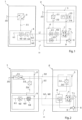
- the Figure 1 shows a schematic diagram known from the prior art Circuit arrangement with external control electronics 1, an interface 10 and a motor control 2 for the EC motor 8 of a fan.
- a PWM signal is conventionally generated and transmitted via the connecting line 45 and, after a galvanic isolation 61, is detected by the motor electronics 2 integrated in the fan and converted by the motor commutation electronics 62 via a motor driver (driver module) 7 into a control signal 71 for the motor 8.
- a speed is generated, which is usually measured by a Hall sensor 9 and transmitted via a galvanic isolation 63 to the control electronics 1 via the interface 10, namely the connecting line 46.
- the control unit evaluates this speed information.
- Both the external control electronics 1 have a mains voltage connection 30 and the motor electronics 2 have a mains voltage connection 50.
- a galvanic isolation 61 and a second galvanic isolation 63 are provided in the motor control 2.
- the one galvanic isolation 61 serves to separate the transmission path from the control electronics 1 to the motor control 2 and the second galvanic isolation 63 is required to separate the transmission path of the speed transmission to the control electronics 1.
- the control electronics 1 provides an internal supply voltage 31 and this is fed into the input of the voltage converter 4.
- the voltage converter 51 provides an internal supply voltage 52 for the motor commutation electronics.
- the control electronics 4 generates by means of the speed controller 42 via a Driver stage 44 uses the target speed 41 to generate the PWM signal for speed control of motor 8.
- the control electronics 4 also receive the actual speed via the return line 46.
- a speed sensor 9 (Hall sensor) is provided for this purpose.
- FIG. 2 an embodiment of a circuit arrangement according to the invention, also with an external control 1, an interface 10 and a motor control 2.
- the same reference numerals in the figures indicate the same structural or functional features. As can be seen, this arrangement only requires a mains connection 30 on the control electronics 1.
- the interface 10 comprises three interface connections 32, 35 and (45, 46) between the control electronics 1 and a motor electronics 2, wherein the voltage supply of the control electronics 1 is supplied as a rectified mains voltage to the motor electronics 2 via the interface connection 32.
- the interface connections 32, 45 between the control electronics 1 and the motor electronics 2 are at a common relative voltage potential compared to the reference potential at the interface connection 35. Furthermore, the arrangement designed in this way only requires one galvanic isolating device 44.
- the reference number 46 refers to the same connecting line as the reference number 45 and represents a bi-directional connecting line as a communication connection.
- the PWM signal with speed feedback known from the state of the art is used in the design according to Figure 2 replaced by this bidirectional communication interface connection 45, 46 between the control electronics 4 and motor commutation electronics 6, which digitally transmits both the speed setpoint and the actual value from the speed sensor 9 of the motor 8. transmits. Since a PWM signal with steep edges no longer has to be transmitted continuously, but only a target value for the speed, which is converted by the commutation electronics 6 via the motor driver 7 directly into a control signal 71 for the motor 8, comparatively slow signals can be transmitted. This also enables the use of slower, cheaper optocouplers for the galvanic isolation.
- the voltage reference via connection 35 for the communication interface is the same as for the rectified mains voltage at connection 32.
- the galvanic isolation takes place in such a way that the communication signal is tied to the mains voltage, i.e. it can be routed via the same cable as the supply voltage of the motor electronics 2. There is no mixing of low-voltage and mains voltage signals and communication therefore only requires one additional connecting cable.
Landscapes
- Engineering & Computer Science (AREA)
- Power Engineering (AREA)
- Control Of Motors That Do Not Use Commutators (AREA)
- Control Of Direct Current Motors (AREA)
Claims (10)
- Dispositif composé d'une électronique de commande (1) d'un appareil comprenant une électronique de régulation (4) et une électronique de moteur (2) d'un moteur à commutation électronique (EC) (8), et d'une interface entre l'électronique de commande (1) et l'électronique de moteur (2) isolée galvaniquement de celle-ci et qui comprend une électronique de commutation de moteur (6), dans lequel l'interface est réalisée avec exactement trois lignes de raccordement (32, 35, 45) entre l'électronique de commande (1) et l'électronique de moteur (2) pour l'alimentation en tension et pour la transmission d'un signal MIL, dans lequel l'une des trois lignes de raccordement est prévue comme une ligne de communication bidirectionnelle, notamment comme une liaison de communication bidirectionnelle (45), entre l'électronique de régulation (4) et l'électronique de commutation de moteur (6) pour transmettre un signal MIL pour la régulation de la vitesse de rotation du moteur EC (8), dans lequel seule l'électronique de commande (1) dispose d'une borne de tension (alternative) de réseau (30) et fournit par l'intermédiaire d'un redresseur (30) la tension de réseau dans une tension d'alimentation redressée pour l'électronique de moteur (2).
- Dispositif selon la revendication 1, caractérisé en ce que les lignes de raccordement (32, 35, 45) sont sur un potentiel de tension commun.
- Dispositif selon l'une quelconque des revendications 1 ou 2, caractérisé en ce qu'une ligne de raccordement (35) fournit à l'électronique de moteur (2) le potentiel de référence qui est formé à la sortie du redresseur (30) à partir d'une tension de réseau au niveau de la borne de tension de réseau (30).
- Dispositif selon la revendication 3, caractérisé en ce que le potentiel de référence est amené à un module d'attaque (7) de l'électronique de moteur (2) par l'intermédiaire de la ligne de raccordement (35) de l'interface.
- Dispositif selon l'une quelconque des revendications précédentes, caractérisé en ce que l'électronique de commande (1) dispose d'un dispositif d'isolation galvanique (44), de préférence réalisé sous forme d'optocoupleur, à partir duquel une ligne de raccordement (44, 45) mène à l'électronique de moteur (2) pour transmettre un signal de valeur de consigne pour la régulation de vitesse de rotation.
- Dispositif selon la revendication 5, caractérisé en ce que l'une des lignes de raccordement (44, 45) est réalisée comme une liaison bidirectionnelle pour transmettre le signal de valeur de consigne pour la régulation de vitesse de rotation afin de transmettre des signaux de valeur réelle de la vitesse de rotation du moteur (8) de l'électronique de moteur (2) à l'électronique de commande (1).
- Dispositif selon l'une quelconque des revendications précédentes, caractérisé en ce que la ligne de raccordement (44, 45) conçue de manière bidirectionnelle selon la revendication 6 est réalisée pour transmettre le signal de valeur de consigne directement à une électronique de commutation (6) de la commande de moteur (2).
- Dispositif selon l'une quelconque des revendications précédentes 5 à 7, caractérisé en ce que le signal de valeur de consigne pour la vitesse de rotation est amené à un module d'attaque (7) de l'électronique de moteur (2) par l'intermédiaire de l'électronique de commutation (6) prévue dans la commande de moteur (2).
- Dispositif selon l'une quelconque des revendications précédentes, caractérisé en ce que l'électronique de commande (1) et l'électronique de moteur (2) sont disposées sur des cartes de circuits imprimés physiquement complètement séparées l'une de l'autre et ne sont reliées électriquement l'une à l'autre en technique de signal que par l'interface.
- Dispositif selon l'une quelconque des revendications précédentes en combinaison avec la revendication 5, caractérisé en ce que la vitesse de transmission des signaux de valeur de consigne est inférieure à la vitesse de transmission des signaux MIL au moins d'un facteur 8, de préférence d'un facteur 10.
Applications Claiming Priority (1)
| Application Number | Priority Date | Filing Date | Title |
|---|---|---|---|
| DE102019109546.8A DE102019109546A1 (de) | 2019-04-11 | 2019-04-11 | Komponentenintegrierte Schnittstelle |
Publications (2)
| Publication Number | Publication Date |
|---|---|
| EP3723268A1 EP3723268A1 (fr) | 2020-10-14 |
| EP3723268B1 true EP3723268B1 (fr) | 2024-05-01 |
Family
ID=69845220
Family Applications (1)
| Application Number | Title | Priority Date | Filing Date |
|---|---|---|---|
| EP20163658.6A Active EP3723268B1 (fr) | 2019-04-11 | 2020-03-17 | Interface intégrée au composant |
Country Status (3)
| Country | Link |
|---|---|
| EP (1) | EP3723268B1 (fr) |
| CN (1) | CN210223036U (fr) |
| DE (1) | DE102019109546A1 (fr) |
Family Cites Families (4)
| Publication number | Priority date | Publication date | Assignee | Title |
|---|---|---|---|---|
| SE526852C2 (sv) * | 2003-06-26 | 2005-11-08 | Kongsberg Automotive Ab | Metod och arrangemang för styrning av likströmsmotor |
| DE102010031244B4 (de) * | 2010-03-19 | 2023-01-12 | Tridonic Ag | Modulares LED-Beleuchtungssystem |
| DE102011076449A1 (de) * | 2011-05-25 | 2012-11-29 | Automotive Lighting Reutlingen Gmbh | Verfahren und Vorrichtung zur Steuerung und/oder Regelung eines Elektromotors |
| DE102016119826A1 (de) * | 2016-10-18 | 2018-04-19 | Ebm-Papst St. Georgen Gmbh & Co. Kg | Vorrichtung zur potentialgetrennten Lüfteransteuerung sowie Lüftersystem und Ansteuerverfahren |
-
2019
- 2019-04-11 DE DE102019109546.8A patent/DE102019109546A1/de not_active Withdrawn
- 2019-05-13 CN CN201920677064.3U patent/CN210223036U/zh not_active Expired - Fee Related
-
2020
- 2020-03-17 EP EP20163658.6A patent/EP3723268B1/fr active Active
Also Published As
| Publication number | Publication date |
|---|---|
| DE102019109546A1 (de) | 2020-10-15 |
| CN210223036U (zh) | 2020-03-31 |
| EP3723268A1 (fr) | 2020-10-14 |
Similar Documents
| Publication | Publication Date | Title |
|---|---|---|
| DE102004059151B4 (de) | Steuervorrichtung für einen Generator eines Kraftfahrzeuges mit mindestens zwei Kommunikationsanschlüssen | |
| EP2013966A1 (fr) | Unité de commande pour un moteur électrique, en particulier pour un moteur à ventilateurs | |
| DE102007005571B4 (de) | Lüfteranordnung mit erhöhter Verfügbarkeit und Verfahren zu ihrem Betrieb | |
| EP3078112B1 (fr) | Actionneur avec capteur de position | |
| EP2898596B1 (fr) | Installation de cyclage thermodynamique | |
| DE102009024572B4 (de) | Motorsteuerungseinrichtung und Motorsteuerungsverfahren | |
| EP3123608B1 (fr) | Etage d'entrée pour controler un moteur et le controle du moteur, notamment pour un moteur électrique | |
| EP3475771B1 (fr) | Dispositif de commande de ventilateur à séparation de potentiel ainsi que système de ventilateurs et procédé de commande | |
| EP3723268B1 (fr) | Interface intégrée au composant | |
| EP3063505B1 (fr) | Capteur de position permettant de détecter une position d'un actionneur | |
| EP0903008B1 (fr) | Dispositif a moteur commute electroniquement | |
| DE19947501C5 (de) | Aktuator-Sensor-Interface-Slave | |
| EP3723269A1 (fr) | Conception d'interface entre une commande et une électronique de commutation des moteurs à courant continu | |
| EP3182607B1 (fr) | Ventilateurs pouvant produire des signaux d'état et les transmettre par l'intermédiaire d'une ligne d'alimentation | |
| DE202019102073U1 (de) | Komponentenintegrierte Schnittstelle | |
| DE202019102074U1 (de) | Schnittstellenauslegung zwischen einer Steuerung und einer Kommutierungselektronik von Gleichstrommotoren | |
| DE102010019083A1 (de) | Verfahren und Synchronisationseinrichtung zur Synchronisierung von mindestens zwei RWA- und Lüftungsklappenantrieben | |
| EP1873899A2 (fr) | Commande de la vitesse du ventilateur et procédé destiné au réglage de la vitesse d'un ventilateur | |
| EP2402182B1 (fr) | Système d'opération d'un moteur courant continu dans une application pour un véhicule | |
| DE102013226603B4 (de) | Sicherheitstechnik-spannungsinsel, stromrichter, versorger, und verfahren zur sicheren ansteuerung von parallel geschalteten leistungsteilen eines stromrichters | |
| WO2019161837A1 (fr) | Contrôleur pour un moteur électrique et actionneur | |
| DE102019218348A1 (de) | Elektrische heizvorrichtung für ein kraftfahrzeug | |
| DE102009039579A1 (de) | Gleichspannungswandler-Anordnung für ein Kraftfahrzeug | |
| DE3310206A1 (de) | Verfahren und schaltungsanordnung zum regeln der drehzahl eines asynchron-motors | |
| DE202014007752U1 (de) | Stromerzeuger zur Bereitstellung eines Wechselstromes und eines Gleichstromes, Generatoranordnung |
Legal Events
| Date | Code | Title | Description |
|---|---|---|---|
| PUAI | Public reference made under article 153(3) epc to a published international application that has entered the european phase |
Free format text: ORIGINAL CODE: 0009012 |
|
| STAA | Information on the status of an ep patent application or granted ep patent |
Free format text: STATUS: THE APPLICATION HAS BEEN PUBLISHED |
|
| AK | Designated contracting states |
Kind code of ref document: A1 Designated state(s): AL AT BE BG CH CY CZ DE DK EE ES FI FR GB GR HR HU IE IS IT LI LT LU LV MC MK MT NL NO PL PT RO RS SE SI SK SM TR |
|
| AX | Request for extension of the european patent |
Extension state: BA ME |
|
| STAA | Information on the status of an ep patent application or granted ep patent |
Free format text: STATUS: REQUEST FOR EXAMINATION WAS MADE |
|
| 17P | Request for examination filed |
Effective date: 20210407 |
|
| RBV | Designated contracting states (corrected) |
Designated state(s): AL AT BE BG CH CY CZ DE DK EE ES FI FR GB GR HR HU IE IS IT LI LT LU LV MC MK MT NL NO PL PT RO RS SE SI SK SM TR |
|
| STAA | Information on the status of an ep patent application or granted ep patent |
Free format text: STATUS: EXAMINATION IS IN PROGRESS |
|
| 17Q | First examination report despatched |
Effective date: 20220502 |
|
| GRAP | Despatch of communication of intention to grant a patent |
Free format text: ORIGINAL CODE: EPIDOSNIGR1 |
|
| STAA | Information on the status of an ep patent application or granted ep patent |
Free format text: STATUS: GRANT OF PATENT IS INTENDED |
|
| RIC1 | Information provided on ipc code assigned before grant |
Ipc: G08C 19/00 20060101ALN20231018BHEP Ipc: H02K 11/30 20160101ALI20231018BHEP Ipc: H02K 11/40 20160101ALI20231018BHEP Ipc: H02P 6/17 20160101ALI20231018BHEP Ipc: H02P 6/08 20160101AFI20231018BHEP |
|
| INTG | Intention to grant announced |
Effective date: 20231102 |
|
| GRAS | Grant fee paid |
Free format text: ORIGINAL CODE: EPIDOSNIGR3 |
|
| P01 | Opt-out of the competence of the unified patent court (upc) registered |
Effective date: 20240212 |
|
| GRAA | (expected) grant |
Free format text: ORIGINAL CODE: 0009210 |
|
| STAA | Information on the status of an ep patent application or granted ep patent |
Free format text: STATUS: THE PATENT HAS BEEN GRANTED |
|
| AK | Designated contracting states |
Kind code of ref document: B1 Designated state(s): AL AT BE BG CH CY CZ DE DK EE ES FI FR GB GR HR HU IE IS IT LI LT LU LV MC MK MT NL NO PL PT RO RS SE SI SK SM TR |
|
| REG | Reference to a national code |
Ref country code: GB Ref legal event code: FG4D Free format text: NOT ENGLISH |
|
| REG | Reference to a national code |
Ref country code: CH Ref legal event code: EP |
|
| REG | Reference to a national code |
Ref country code: IE Ref legal event code: FG4D Free format text: LANGUAGE OF EP DOCUMENT: GERMAN |
|
| REG | Reference to a national code |
Ref country code: DE Ref legal event code: R096 Ref document number: 502020007805 Country of ref document: DE |
|
| REG | Reference to a national code |
Ref country code: LT Ref legal event code: MG9D |
|
| REG | Reference to a national code |
Ref country code: NL Ref legal event code: MP Effective date: 20240501 |
|
| PG25 | Lapsed in a contracting state [announced via postgrant information from national office to epo] |
Ref country code: IS Free format text: LAPSE BECAUSE OF FAILURE TO SUBMIT A TRANSLATION OF THE DESCRIPTION OR TO PAY THE FEE WITHIN THE PRESCRIBED TIME-LIMIT Effective date: 20240901 |
|
| PG25 | Lapsed in a contracting state [announced via postgrant information from national office to epo] |
Ref country code: BG Free format text: LAPSE BECAUSE OF FAILURE TO SUBMIT A TRANSLATION OF THE DESCRIPTION OR TO PAY THE FEE WITHIN THE PRESCRIBED TIME-LIMIT Effective date: 20240501 |
|
| PG25 | Lapsed in a contracting state [announced via postgrant information from national office to epo] |
Ref country code: HR Free format text: LAPSE BECAUSE OF FAILURE TO SUBMIT A TRANSLATION OF THE DESCRIPTION OR TO PAY THE FEE WITHIN THE PRESCRIBED TIME-LIMIT Effective date: 20240501 Ref country code: FI Free format text: LAPSE BECAUSE OF FAILURE TO SUBMIT A TRANSLATION OF THE DESCRIPTION OR TO PAY THE FEE WITHIN THE PRESCRIBED TIME-LIMIT Effective date: 20240501 |
|
| PG25 | Lapsed in a contracting state [announced via postgrant information from national office to epo] |
Ref country code: GR Free format text: LAPSE BECAUSE OF FAILURE TO SUBMIT A TRANSLATION OF THE DESCRIPTION OR TO PAY THE FEE WITHIN THE PRESCRIBED TIME-LIMIT Effective date: 20240802 |
|
| PG25 | Lapsed in a contracting state [announced via postgrant information from national office to epo] |
Ref country code: PT Free format text: LAPSE BECAUSE OF FAILURE TO SUBMIT A TRANSLATION OF THE DESCRIPTION OR TO PAY THE FEE WITHIN THE PRESCRIBED TIME-LIMIT Effective date: 20240902 |
|
| PG25 | Lapsed in a contracting state [announced via postgrant information from national office to epo] |
Ref country code: NL Free format text: LAPSE BECAUSE OF FAILURE TO SUBMIT A TRANSLATION OF THE DESCRIPTION OR TO PAY THE FEE WITHIN THE PRESCRIBED TIME-LIMIT Effective date: 20240501 |
|
| PG25 | Lapsed in a contracting state [announced via postgrant information from national office to epo] |
Ref country code: ES Free format text: LAPSE BECAUSE OF FAILURE TO SUBMIT A TRANSLATION OF THE DESCRIPTION OR TO PAY THE FEE WITHIN THE PRESCRIBED TIME-LIMIT Effective date: 20240501 |
|
| PG25 | Lapsed in a contracting state [announced via postgrant information from national office to epo] |
Ref country code: PL Free format text: LAPSE BECAUSE OF FAILURE TO SUBMIT A TRANSLATION OF THE DESCRIPTION OR TO PAY THE FEE WITHIN THE PRESCRIBED TIME-LIMIT Effective date: 20240501 |
|
| PG25 | Lapsed in a contracting state [announced via postgrant information from national office to epo] |
Ref country code: LV Free format text: LAPSE BECAUSE OF FAILURE TO SUBMIT A TRANSLATION OF THE DESCRIPTION OR TO PAY THE FEE WITHIN THE PRESCRIBED TIME-LIMIT Effective date: 20240501 |
|
| PG25 | Lapsed in a contracting state [announced via postgrant information from national office to epo] |
Ref country code: PT Free format text: LAPSE BECAUSE OF FAILURE TO SUBMIT A TRANSLATION OF THE DESCRIPTION OR TO PAY THE FEE WITHIN THE PRESCRIBED TIME-LIMIT Effective date: 20240902 Ref country code: PL Free format text: LAPSE BECAUSE OF FAILURE TO SUBMIT A TRANSLATION OF THE DESCRIPTION OR TO PAY THE FEE WITHIN THE PRESCRIBED TIME-LIMIT Effective date: 20240501 Ref country code: NO Free format text: LAPSE BECAUSE OF FAILURE TO SUBMIT A TRANSLATION OF THE DESCRIPTION OR TO PAY THE FEE WITHIN THE PRESCRIBED TIME-LIMIT Effective date: 20240801 Ref country code: NL Free format text: LAPSE BECAUSE OF FAILURE TO SUBMIT A TRANSLATION OF THE DESCRIPTION OR TO PAY THE FEE WITHIN THE PRESCRIBED TIME-LIMIT Effective date: 20240501 Ref country code: LV Free format text: LAPSE BECAUSE OF FAILURE TO SUBMIT A TRANSLATION OF THE DESCRIPTION OR TO PAY THE FEE WITHIN THE PRESCRIBED TIME-LIMIT Effective date: 20240501 Ref country code: IS Free format text: LAPSE BECAUSE OF FAILURE TO SUBMIT A TRANSLATION OF THE DESCRIPTION OR TO PAY THE FEE WITHIN THE PRESCRIBED TIME-LIMIT Effective date: 20240901 Ref country code: HR Free format text: LAPSE BECAUSE OF FAILURE TO SUBMIT A TRANSLATION OF THE DESCRIPTION OR TO PAY THE FEE WITHIN THE PRESCRIBED TIME-LIMIT Effective date: 20240501 Ref country code: GR Free format text: LAPSE BECAUSE OF FAILURE TO SUBMIT A TRANSLATION OF THE DESCRIPTION OR TO PAY THE FEE WITHIN THE PRESCRIBED TIME-LIMIT Effective date: 20240802 Ref country code: FI Free format text: LAPSE BECAUSE OF FAILURE TO SUBMIT A TRANSLATION OF THE DESCRIPTION OR TO PAY THE FEE WITHIN THE PRESCRIBED TIME-LIMIT Effective date: 20240501 Ref country code: ES Free format text: LAPSE BECAUSE OF FAILURE TO SUBMIT A TRANSLATION OF THE DESCRIPTION OR TO PAY THE FEE WITHIN THE PRESCRIBED TIME-LIMIT Effective date: 20240501 Ref country code: BG Free format text: LAPSE BECAUSE OF FAILURE TO SUBMIT A TRANSLATION OF THE DESCRIPTION OR TO PAY THE FEE WITHIN THE PRESCRIBED TIME-LIMIT Effective date: 20240501 Ref country code: RS Free format text: LAPSE BECAUSE OF FAILURE TO SUBMIT A TRANSLATION OF THE DESCRIPTION OR TO PAY THE FEE WITHIN THE PRESCRIBED TIME-LIMIT Effective date: 20240801 |
|
| PG25 | Lapsed in a contracting state [announced via postgrant information from national office to epo] |
Ref country code: DK Free format text: LAPSE BECAUSE OF FAILURE TO SUBMIT A TRANSLATION OF THE DESCRIPTION OR TO PAY THE FEE WITHIN THE PRESCRIBED TIME-LIMIT Effective date: 20240501 |
|
| PG25 | Lapsed in a contracting state [announced via postgrant information from national office to epo] |
Ref country code: EE Free format text: LAPSE BECAUSE OF FAILURE TO SUBMIT A TRANSLATION OF THE DESCRIPTION OR TO PAY THE FEE WITHIN THE PRESCRIBED TIME-LIMIT Effective date: 20240501 |
|
| PG25 | Lapsed in a contracting state [announced via postgrant information from national office to epo] |
Ref country code: CZ Free format text: LAPSE BECAUSE OF FAILURE TO SUBMIT A TRANSLATION OF THE DESCRIPTION OR TO PAY THE FEE WITHIN THE PRESCRIBED TIME-LIMIT Effective date: 20240501 |
|
| PG25 | Lapsed in a contracting state [announced via postgrant information from national office to epo] |
Ref country code: SK Free format text: LAPSE BECAUSE OF FAILURE TO SUBMIT A TRANSLATION OF THE DESCRIPTION OR TO PAY THE FEE WITHIN THE PRESCRIBED TIME-LIMIT Effective date: 20240501 Ref country code: RO Free format text: LAPSE BECAUSE OF FAILURE TO SUBMIT A TRANSLATION OF THE DESCRIPTION OR TO PAY THE FEE WITHIN THE PRESCRIBED TIME-LIMIT Effective date: 20240501 |
|
| PG25 | Lapsed in a contracting state [announced via postgrant information from national office to epo] |
Ref country code: SM Free format text: LAPSE BECAUSE OF FAILURE TO SUBMIT A TRANSLATION OF THE DESCRIPTION OR TO PAY THE FEE WITHIN THE PRESCRIBED TIME-LIMIT Effective date: 20240501 |
|
| PG25 | Lapsed in a contracting state [announced via postgrant information from national office to epo] |
Ref country code: SM Free format text: LAPSE BECAUSE OF FAILURE TO SUBMIT A TRANSLATION OF THE DESCRIPTION OR TO PAY THE FEE WITHIN THE PRESCRIBED TIME-LIMIT Effective date: 20240501 Ref country code: SK Free format text: LAPSE BECAUSE OF FAILURE TO SUBMIT A TRANSLATION OF THE DESCRIPTION OR TO PAY THE FEE WITHIN THE PRESCRIBED TIME-LIMIT Effective date: 20240501 Ref country code: RO Free format text: LAPSE BECAUSE OF FAILURE TO SUBMIT A TRANSLATION OF THE DESCRIPTION OR TO PAY THE FEE WITHIN THE PRESCRIBED TIME-LIMIT Effective date: 20240501 Ref country code: EE Free format text: LAPSE BECAUSE OF FAILURE TO SUBMIT A TRANSLATION OF THE DESCRIPTION OR TO PAY THE FEE WITHIN THE PRESCRIBED TIME-LIMIT Effective date: 20240501 Ref country code: DK Free format text: LAPSE BECAUSE OF FAILURE TO SUBMIT A TRANSLATION OF THE DESCRIPTION OR TO PAY THE FEE WITHIN THE PRESCRIBED TIME-LIMIT Effective date: 20240501 Ref country code: CZ Free format text: LAPSE BECAUSE OF FAILURE TO SUBMIT A TRANSLATION OF THE DESCRIPTION OR TO PAY THE FEE WITHIN THE PRESCRIBED TIME-LIMIT Effective date: 20240501 |
|
| REG | Reference to a national code |
Ref country code: DE Ref legal event code: R097 Ref document number: 502020007805 Country of ref document: DE |
|
| PG25 | Lapsed in a contracting state [announced via postgrant information from national office to epo] |
Ref country code: IT Free format text: LAPSE BECAUSE OF FAILURE TO SUBMIT A TRANSLATION OF THE DESCRIPTION OR TO PAY THE FEE WITHIN THE PRESCRIBED TIME-LIMIT Effective date: 20240501 |
|
| PLBE | No opposition filed within time limit |
Free format text: ORIGINAL CODE: 0009261 |
|
| STAA | Information on the status of an ep patent application or granted ep patent |
Free format text: STATUS: NO OPPOSITION FILED WITHIN TIME LIMIT |
|
| 26N | No opposition filed |
Effective date: 20250204 |
|
| PG25 | Lapsed in a contracting state [announced via postgrant information from national office to epo] |
Ref country code: SI Free format text: LAPSE BECAUSE OF FAILURE TO SUBMIT A TRANSLATION OF THE DESCRIPTION OR TO PAY THE FEE WITHIN THE PRESCRIBED TIME-LIMIT Effective date: 20240501 |
|
| PG25 | Lapsed in a contracting state [announced via postgrant information from national office to epo] |
Ref country code: SE Free format text: LAPSE BECAUSE OF FAILURE TO SUBMIT A TRANSLATION OF THE DESCRIPTION OR TO PAY THE FEE WITHIN THE PRESCRIBED TIME-LIMIT Effective date: 20240501 |
|
| PG25 | Lapsed in a contracting state [announced via postgrant information from national office to epo] |
Ref country code: MC Free format text: LAPSE BECAUSE OF FAILURE TO SUBMIT A TRANSLATION OF THE DESCRIPTION OR TO PAY THE FEE WITHIN THE PRESCRIBED TIME-LIMIT Effective date: 20240501 |
|
| REG | Reference to a national code |
Ref country code: CH Ref legal event code: H13 Free format text: ST27 STATUS EVENT CODE: U-0-0-H10-H13 (AS PROVIDED BY THE NATIONAL OFFICE) Effective date: 20251023 |
|
| PG25 | Lapsed in a contracting state [announced via postgrant information from national office to epo] |
Ref country code: LU Free format text: LAPSE BECAUSE OF NON-PAYMENT OF DUE FEES Effective date: 20250317 |
|
| GBPC | Gb: european patent ceased through non-payment of renewal fee |
Effective date: 20250317 |
|
| REG | Reference to a national code |
Ref country code: BE Ref legal event code: MM Effective date: 20250331 |
|
| PG25 | Lapsed in a contracting state [announced via postgrant information from national office to epo] |
Ref country code: GB Free format text: LAPSE BECAUSE OF NON-PAYMENT OF DUE FEES Effective date: 20250317 |
|
| PG25 | Lapsed in a contracting state [announced via postgrant information from national office to epo] |
Ref country code: FR Free format text: LAPSE BECAUSE OF NON-PAYMENT OF DUE FEES Effective date: 20250331 |
|
| PG25 | Lapsed in a contracting state [announced via postgrant information from national office to epo] |
Ref country code: BE Free format text: LAPSE BECAUSE OF NON-PAYMENT OF DUE FEES Effective date: 20250331 |
|
| PG25 | Lapsed in a contracting state [announced via postgrant information from national office to epo] |
Ref country code: CH Free format text: LAPSE BECAUSE OF NON-PAYMENT OF DUE FEES Effective date: 20250331 |
|
| PG25 | Lapsed in a contracting state [announced via postgrant information from national office to epo] |
Ref country code: IE Free format text: LAPSE BECAUSE OF NON-PAYMENT OF DUE FEES Effective date: 20250317 |
|
| PGFP | Annual fee paid to national office [announced via postgrant information from national office to epo] |
Ref country code: DE Payment date: 20260320 Year of fee payment: 7 |