EP3723576B1 - Vorrichtung und verfahren zur kontaminationsfreien durchführung einer endoskopischen untersuchung - Google Patents
Vorrichtung und verfahren zur kontaminationsfreien durchführung einer endoskopischen untersuchung Download PDFInfo
- Publication number
- EP3723576B1 EP3723576B1 EP19728861.6A EP19728861A EP3723576B1 EP 3723576 B1 EP3723576 B1 EP 3723576B1 EP 19728861 A EP19728861 A EP 19728861A EP 3723576 B1 EP3723576 B1 EP 3723576B1
- Authority
- EP
- European Patent Office
- Prior art keywords
- hose
- proximal
- shaft
- endoscope
- opening
- Prior art date
- Legal status (The legal status is an assumption and is not a legal conclusion. Google has not performed a legal analysis and makes no representation as to the accuracy of the status listed.)
- Active
Links
Images








Classifications
-
- A—HUMAN NECESSITIES
- A61—MEDICAL OR VETERINARY SCIENCE; HYGIENE
- A61B—DIAGNOSIS; SURGERY; IDENTIFICATION
- A61B1/00—Instruments for performing medical examinations of the interior of cavities or tubes of the body by visual or photographical inspection, e.g. endoscopes; Illuminating arrangements therefor
- A61B1/00142—Instruments for performing medical examinations of the interior of cavities or tubes of the body by visual or photographical inspection, e.g. endoscopes; Illuminating arrangements therefor with means for preventing contamination, e.g. by using a sanitary sheath
-
- A—HUMAN NECESSITIES
- A61—MEDICAL OR VETERINARY SCIENCE; HYGIENE
- A61B—DIAGNOSIS; SURGERY; IDENTIFICATION
- A61B1/00—Instruments for performing medical examinations of the interior of cavities or tubes of the body by visual or photographical inspection, e.g. endoscopes; Illuminating arrangements therefor
- A61B1/00064—Constructional details of the endoscope body
- A61B1/00066—Proximal part of endoscope body, e.g. handles
- A61B1/00068—Valve switch arrangements
-
- A—HUMAN NECESSITIES
- A61—MEDICAL OR VETERINARY SCIENCE; HYGIENE
- A61B—DIAGNOSIS; SURGERY; IDENTIFICATION
- A61B1/00—Instruments for performing medical examinations of the interior of cavities or tubes of the body by visual or photographical inspection, e.g. endoscopes; Illuminating arrangements therefor
- A61B1/00064—Constructional details of the endoscope body
- A61B1/00071—Insertion part of the endoscope body
- A61B1/0008—Insertion part of the endoscope body characterised by distal tip features
- A61B1/00091—Nozzles
-
- A—HUMAN NECESSITIES
- A61—MEDICAL OR VETERINARY SCIENCE; HYGIENE
- A61B—DIAGNOSIS; SURGERY; IDENTIFICATION
- A61B1/00—Instruments for performing medical examinations of the interior of cavities or tubes of the body by visual or photographical inspection, e.g. endoscopes; Illuminating arrangements therefor
- A61B1/00064—Constructional details of the endoscope body
- A61B1/00071—Insertion part of the endoscope body
- A61B1/0008—Insertion part of the endoscope body characterised by distal tip features
- A61B1/00094—Suction openings
-
- A—HUMAN NECESSITIES
- A61—MEDICAL OR VETERINARY SCIENCE; HYGIENE
- A61B—DIAGNOSIS; SURGERY; IDENTIFICATION
- A61B1/00—Instruments for performing medical examinations of the interior of cavities or tubes of the body by visual or photographical inspection, e.g. endoscopes; Illuminating arrangements therefor
- A61B1/00064—Constructional details of the endoscope body
- A61B1/00071—Insertion part of the endoscope body
- A61B1/0008—Insertion part of the endoscope body characterised by distal tip features
- A61B1/00096—Optical elements
-
- A—HUMAN NECESSITIES
- A61—MEDICAL OR VETERINARY SCIENCE; HYGIENE
- A61B—DIAGNOSIS; SURGERY; IDENTIFICATION
- A61B1/00—Instruments for performing medical examinations of the interior of cavities or tubes of the body by visual or photographical inspection, e.g. endoscopes; Illuminating arrangements therefor
- A61B1/00112—Connection or coupling means
-
- A—HUMAN NECESSITIES
- A61—MEDICAL OR VETERINARY SCIENCE; HYGIENE
- A61B—DIAGNOSIS; SURGERY; IDENTIFICATION
- A61B1/00—Instruments for performing medical examinations of the interior of cavities or tubes of the body by visual or photographical inspection, e.g. endoscopes; Illuminating arrangements therefor
- A61B1/00147—Holding or positioning arrangements
- A61B1/00148—Holding or positioning arrangements using anchoring means
-
- A—HUMAN NECESSITIES
- A61—MEDICAL OR VETERINARY SCIENCE; HYGIENE
- A61B—DIAGNOSIS; SURGERY; IDENTIFICATION
- A61B1/00—Instruments for performing medical examinations of the interior of cavities or tubes of the body by visual or photographical inspection, e.g. endoscopes; Illuminating arrangements therefor
- A61B1/012—Instruments for performing medical examinations of the interior of cavities or tubes of the body by visual or photographical inspection, e.g. endoscopes; Illuminating arrangements therefor characterised by internal passages or accessories therefor
- A61B1/0125—Endoscope within endoscope
-
- A—HUMAN NECESSITIES
- A61—MEDICAL OR VETERINARY SCIENCE; HYGIENE
- A61B—DIAGNOSIS; SURGERY; IDENTIFICATION
- A61B1/00—Instruments for performing medical examinations of the interior of cavities or tubes of the body by visual or photographical inspection, e.g. endoscopes; Illuminating arrangements therefor
- A61B1/012—Instruments for performing medical examinations of the interior of cavities or tubes of the body by visual or photographical inspection, e.g. endoscopes; Illuminating arrangements therefor characterised by internal passages or accessories therefor
- A61B1/015—Control of fluid supply or evacuation
-
- A—HUMAN NECESSITIES
- A61—MEDICAL OR VETERINARY SCIENCE; HYGIENE
- A61B—DIAGNOSIS; SURGERY; IDENTIFICATION
- A61B1/00—Instruments for performing medical examinations of the interior of cavities or tubes of the body by visual or photographical inspection, e.g. endoscopes; Illuminating arrangements therefor
- A61B1/012—Instruments for performing medical examinations of the interior of cavities or tubes of the body by visual or photographical inspection, e.g. endoscopes; Illuminating arrangements therefor characterised by internal passages or accessories therefor
- A61B1/018—Instruments for performing medical examinations of the interior of cavities or tubes of the body by visual or photographical inspection, e.g. endoscopes; Illuminating arrangements therefor characterised by internal passages or accessories therefor for receiving instruments
-
- A—HUMAN NECESSITIES
- A61—MEDICAL OR VETERINARY SCIENCE; HYGIENE
- A61B—DIAGNOSIS; SURGERY; IDENTIFICATION
- A61B1/00—Instruments for performing medical examinations of the interior of cavities or tubes of the body by visual or photographical inspection, e.g. endoscopes; Illuminating arrangements therefor
- A61B1/31—Instruments for performing medical examinations of the interior of cavities or tubes of the body by visual or photographical inspection, e.g. endoscopes; Illuminating arrangements therefor for the rectum, e.g. proctoscopes, sigmoidoscopes, colonoscopes
-
- A—HUMAN NECESSITIES
- A61—MEDICAL OR VETERINARY SCIENCE; HYGIENE
- A61B—DIAGNOSIS; SURGERY; IDENTIFICATION
- A61B1/00—Instruments for performing medical examinations of the interior of cavities or tubes of the body by visual or photographical inspection, e.g. endoscopes; Illuminating arrangements therefor
- A61B1/06—Instruments for performing medical examinations of the interior of cavities or tubes of the body by visual or photographical inspection, e.g. endoscopes; Illuminating arrangements therefor with illuminating arrangements
Definitions
- the present invention relates to an endoscope with a contamination protection device.
- Medical endoscopy is a diagnostic method for examining body openings or cavities, which also offers the possibility of carrying out minimally invasive surgical interventions. The procedure is based on inserting an imaging probe into the body opening to be examined.
- Endoscopes are used for this purpose, which consist of a handle and a rigid or flexible shaft connected thereto, at the tip of which devices for illumination and imaging are provided.
- illumination either the light from a light source arranged outside the endoscope is used, which is conducted through fiber optic bundles running inside the endoscope shaft, or light generated by light sources, in particular LEDs, integrated into the shaft tip, which is more common in today's endoscopes.
- an optical system is arranged at the tip of the shaft, the image of which is registered by a video chip in the most modern endoscopes, processed and read out via a data line that also runs in the shaft.
- an air nozzle is also provided at the tip of the shaft, which can be pressurized via a channel running inside the shaft from pumps or irrigators arranged outside the endoscope.
- the water nozzle is also supplied via a water channel running inside the socket.
- endoscopes usually have an instrumentation channel running through the shaft, through which micromechanical devices such as forceps, grippers or loops on Bowden cables can be guided into the examination room in order to carry out a biopsy, for example.
- the instrument channel can also be used for suction.
- the instrument channel ends at its proximal end in the area of the handle in a Y-shaped distributor piece, which offers both accessibility for an instrument and a connection option for a pump via its two proximal legs.
- Valves for air, water and suction are provided on the handle for operation by the examining doctor, as well as operating elements for angling and fine positioning of the shaft tip, which is controlled by Bowden cables running in the shaft.
- the shaft is roughly positioned in the body opening to be examined by manual advance or retraction.
- the instrumentation mechanism is operated via a separate operating element on the proximal end of the instrument.
- Contamination protection devices for medical endoscopes are known in the prior art. This is how the patent describes it EP1578255B1 a protective cover made of an elastic material which, starting from its tip, is pulled over the endoscope shaft like a condom. At least in the area of the endoscope optics, this cover consists of an optically transparent material in order not to impair the endoscopic imaging. Since the working channels running inside the endoscope shaft are no longer accessible when using such a protective cover, the patent teaches providing separate air, water and instrumentation channels, which are to be arranged between the endoscope shaft and the protective cover and are airtight, watertight and germ-tight at the distal end connected to the protective cover. When using such a protective device according to the prior art, direct contamination of the endoscope during the examination can be avoided.
- the present invention aims to solve the problem of ensuring reliable and comprehensive protection against contamination for endoscopic examinations, which drastically reduces or avoids contamination of the endoscope, the examination environment and the medical staff, but does not result in any restriction in the handling and usability of the endoscope .
- the essential idea of the present invention is to provide a protective volume between the patient's body opening to be examined and the proximal end of the inserted endoscope shaft, which collects all bodily fluids released during the examination and keeps them away from contact with the environment.
- This volume is delimited by an inner sleeve, which essentially corresponds to the protective sleeve on the endoscope shaft described in the prior art, and by a larger outer sleeve, which is attached to the inner sleeve at the proximal end in an airtight, watertight and germ-tight manner.
- suitable means In order to completely seal off the protective volume spanned according to the invention by the outer and inner sleeves from the examination environment, suitable means must be provided at the distal end of the outer sleeve. These consist of connecting pieces which can be connected to devices according to the invention held by the patient.
- such a device For colonoscopic examination of the intestine, such a device is represented by a special pair of diapers for the patient to be examined, which has an opening with a receiving part to which the connecting piece of the outer cover can be connected in an airtight, watertight and germ-tight manner.
- the protective volume is expanded by a section of the diaper and is essentially closed off from the examination environment when the diaper fits snugly and tightly on the patient.
- a suitable teething ring can be used in gastroscopic examinations of the esophagus or the stomach to receive the connection piece of the outer shell, on which a connection part according to the invention is formed.
- a teething ring can be extended like a mask around the jaw area, care being taken to ensure that this does not significantly impair the patient's breathing activity.
- an appropriately dimensioned partition can be positioned between the patient and the medical personnel performing the examination.
- an opening that is suitably arranged relative to the patient bed is to be provided on this, which is provided with a receiving part for connection to the connection piece of the outer shell.
- connection between the connecting part and the connection piece should be airtight, watertight and germ-tight and secured against unintentional opening while the endoscopy is being carried out.
- Suitable screw, plug, clamp or magnetic connections are known for this purpose.
- the outer sleeve can be extended beyond the proximal end of the inner sleeve and also protectively enclose the handle of the endoscope including the handle attachment.
- the inner and outer shell should be made of a material commonly used for medical purposes, which is airtight and watertight and impermeable to germs. It must also have a sufficient degree of resistance to mechanical wear and tear, such as tearing or abrasion, as well as chemical resistance to substances encountered in the course of endoscopic examinations, such as acids or fats.
- the inner and outer shell should in particular be easy to roll up.
- Polybutene (PB) or cycloolefin polymers (COP), for example, are suitable polymeric materials.
- the present invention teaches in an advantageous embodiment the use of a working hose that lines the instrument channel over its entire length and protrudes from the instrument channel opening behind the proximal end of the shaft, which is required in commercially available endoscopes without contamination protection for inserting the instruments is used, ie not for suction.
- the working hose ends in a working hose opening on the face side, to which it is seamlessly formed.
- the working hose In order to be able to use the working hose both for passing through the device and for suction, according to the invention it ends behind the proximal instrument channel opening in a y-shaped two-way hose distributor, which is inserted into a suitable receptacle on the holder of a handle attachment or alternatively attached directly to the proximal instrument channel opening.
- the grip attachment of the first variant can also include attachments for the valves, ie the air valve, water valve and the suction valve.
- the valves ie the air valve, water valve and the suction valve.
- the working hose opens into the distal end of this hose distributor, so that it is accessible for an instrument through one of the two proximal legs of the hose distributor and through the other for suction.
- the suction is controlled via a suction valve which is also provided on the holder of the handle attachment and which is connected via a suction hose to a proximal end of the two-way hose distributor.
- the contamination protection according to the invention can also have more than one working hose, in particular one working hose per instrumentation channel of the endoscope.
- water or air hose there can also be more than one water or air hose.
- endoscopes with an additional water channel are known, also referred to as a jet channel, which opens freely in the tip of the endoscope and is not intended for rinsing the optics, but for rinsing the operation or examination site with water.
- the protection against contamination according to the invention can be supplemented by an additional water hose including a valve.
- the water hose can also have a double lumen, with one lumen being used for flushing the optics and the other as a jet channel.
- the two-way hose distributor is integrated into the outer sleeve, i.e. welded to it in an airtight, watertight and germ-tight manner.
- an instrument protection according to the invention is connected to the proximal end of the two-way hose distributor provided for inserting an instrument.
- This is used to pull the instrument pulled out of the working channel after the end of the instrumentation process, together with the associated Bowden cables and any tissue sample taken, into a protective instrument hose and thus to protect medical staff and the examination environment from contact with adhering dirt.
- the length of this instrument hose is consequently to be dimensioned greater than the length of the working hose, so that the entire contaminated section of the instrument and the Bowden cables can be accommodated in it.
- the two ends of the instrument hose are each provided with a cap with an opening on the front, which is used to connect to the two-way hose distributor or a handle of the instrument.
- the instrument hose should consist of a material that can be pushed together like a bellows, so that the entire instrument protection can be compressed to a small extent, which ensures a clear and compact attachment to the handle attachment.
- the present invention teaches the advantageous design of the distal end section of the inner sleeve in the form of a rigid cap which is placed on a clamping bracket which encompasses the outer surface of the endoscope shaft.
- the plug-in connection is achieved by inserting a tongue running around the clamping bracket into a corresponding groove on the inside the cap snaps into place.
- a bracket-like clamp extending over a part of the circumference of the shaft can be formed on it, by means of which the circumference of the open end of the elastic cap can be expanded to such an extent that it can be pulled away again by exerting the appropriate force loosen the spring of the clamping bracket and pull it off the tip of the shaft.
- the cap can also be clamped onto the tip of the shank without using a clamping bracket with the aid of axially extending elastic branches formed on the open end face of the cap.
- the spring should have appropriate recesses, and in an advantageous embodiment, the hoses should be guided into the interior of the cap and open into openings on the end face.
- the clamp strap that fixes the cap should be underlaid with a seal, which can be made of silicone, Teflon, EPDM rubber or a self-adhesive adhesive.
- the inner and outer sleeves are attached to the proximal end of the endoscope shaft.
- another clamping bracket with a seal underneath can be used, on which the inner and outer shell rest and are fixed by a circumferential clamp.
- proximal nor the distal clamp has to be removed between two contamination-proof examinations, which advantageously reduces the time required to prepare the endoscope for another examination.
- the inner and outer shell in one piece in such a way that they are connected to one another at the proximal end of the inner shell.
- Such a connection can be realized in production, for example, by a welding process, such as ultrasonic welding, which is suitable for connecting polymer materials.
- a welding process such as ultrasonic welding
- the inner sleeve along the endoscope shaft can advantageously be lined with a flexible fabric tube.
- a suitable leak test method would be the differential pressure method, for example.
- the distal end of the outer shell with the connection piece that may be molded onto it is to be connected to the test device so that the leak test applies to the protective volume spanned between the inner and outer shell. It is also necessary to seal the air and water hoses, e.g. with suitable plugs.
- such a sealing plug should be inserted into the proximal end of the hose so that the instrumentation channel lined with the working hose in the endoscope shaft is also checked in the course of the leak test.
- the outer shell at its distal end as well as the air, water and, if applicable, working hose in the area of the handle are to be severed in such a way that the severed ends are sealed airtight. This can be done, for example, using curling tongs.
- the leak test that follows the examination can also be carried out on the contamination protection device that has already been dismantled.
- the proximal end of the working tube which must be opened again for this purpose, should be used as access for the leak test device to the contaminated volume of the contamination protection device. If, in a simpler embodiment of the contamination protection device, there is no working hose, a new opening can be cut into the outer shell as access instead.
- the International Publication WO 2009/086396 A1 describes a sleeve for an endoscope with a cap which can be placed on the distal end of the endoscope shaft, and a rolled-up, flexible, elongate tube attached to the cap, which can be rolled along the endoscope shaft after the cap has been put on.
- the present invention aims to solve the problem of ensuring reliable and comprehensive protection against contamination for endoscopic examinations, which drastically reduces or avoids contamination of the endoscope, the examination environment and the medical staff, but does not result in any restriction in the handling and usability of the endoscope .
- the essential idea of the present invention is to provide a protective volume between the patient's body opening to be examined and the proximal end of the inserted endoscope shaft, which collects all bodily fluids released during the examination and from contact with the environment keeps away.
- This volume is delimited by an inner sleeve, which essentially corresponds to the protective sleeve on the endoscope shaft described in the prior art, and by a larger outer sleeve, which is attached to the inner sleeve at the proximal end in an airtight, watertight and germ-tight manner.
- the part of the endoscope inserted into the body opening to be examined in a patient which is completed in that the instrumentation channel 10 running inside the endoscope shaft 1 is lined by the working channel adjoining the working channel opening 30c.
- the endoscope shaft sealed in this way is encased by the outer sleeve 6 so that the intermediate space forms a protective volume in which body fluids escaping from the patient's body opening during the endoscopic examination are collected.
- This protective volume is sealed off on the patient side by the connecting piece 61 provided on the outer cover 6, which can be connected, for example, to a suitable pair of diapers 7a or a teething ring 7b.
- the sealing of the protective volume at the proximal end of the endoscope shaft 1 is 1 illustrated embodiment is ensured by the clamp 91, which presses the inner and outer shell 3, 6 onto a proximal clamping bracket 93 located underneath. The ends of the inner and outer shell 3, 6 that protrude beyond this are accommodated in the clamp 94 and are thus secured against tearing, for example.
- Corresponding slits are provided in the proximal clamping bracket 93 located under the clamp 91, outer and inner shell 6, 3 for the passage of air and water hoses 4a, 4b beyond the proximal end of the protective volume.
- the handle attachment 21 with the valve holder 22 and the instrument holder 23 is placed on the handle 2 of the endoscope, into which air-water and suction valve 5a, 5b, 5d and the two-way hose distributor 24 are inserted.
- the two-way hose distributor 24, which is connected at its distal end to the working hose 4c protruding from the proximal instrument channel opening 102, enables access to the instrument channel 10 via its two proximal ends.
- the suction hose 4d and the associated suction valve 5d are connected to the angled leg of the hose distributor 24 .
- Air and water valve 5a, 5b are connected to the distal end of the endoscope shaft leading air and water hoses 4a, 4b connected.
- the hoses running out of the valves 5a, 5b, 5d from the endoscope are connected to suitable devices for applying negative or positive pressure or water, which are not claimed within the scope of the present invention.
- FIG. 2 shows a detailed view of the distal end of an advantageous embodiment of the endoscope according to the invention.
- the lighting devices 12, the optics 11 used for imaging and the nozzle 13, which is not operated when the endoscope is used according to the invention, are located under the optically transparent end face 30 of the inner sleeve 3 or the cap 31.
- the end face 30 is pierced by the air hose 4a, which ends in the air hose opening 30a, the water hose 4b with the water hose opening 30b, and the working hose 4c running in the instrumentation channel 10 with the working hose opening 30c.
- the distal clamping bracket 96 can be seen, which encloses the outer surface of the endoscope shaft 1 and is underlaid by the distal seal 95 and acts as a receptacle for the cap 31 placed thereon.
- the Figures 3a to 3d show the assembly of a clamping bracket 96 on the distal end of the endoscope shaft 1.
- both its axial and its radial positioning on the lateral surface of the endoscope shaft 1 are important when assembling the clamping bracket 96. It must be ensured that the end face 30 of the cap 31 is spaced from the end face of the endoscope shaft in such a way that, on the one hand, the viewing angle of the endoscope optics 11 is not significantly restricted and, on the other hand, there is sufficient space around the air and water hoses 4a, 4b from the outside of the endoscope shaft 1 to the end face 30 of the cap 31.
- the working tube opening 30c which is arranged in an advantageous embodiment on the end face 30 of the cap 31, is placed in line with the instrument channel opening 101 on the end face of the endoscope shaft.
- the air and water hose openings 30a, 30b must not cover or shade the lighting devices 12 at the shaft tip.
- the present invention therefore teaches the advantageous use of a positioning aid 960 for mounting the clamping bracket 96, as in Figures 3a to 3d illustrated.
- the positioning aid 960 is connected to the clamping bracket 96 via predetermined breaking points and is broken off after assembly has been completed.
- the essential elements of the positioning aid 960 are a pin which is arranged on its end face and points inward and which is inserted into the instrument channel opening 101, and an opening at the end which is placed over the nozzle 13 protruding from the tip of the shaft. This clearly defines the radial orientation of the positioning aid together with the clamp bracket attached to it, and it is ensured that the cutouts provided for the passage of air and water hoses 4a, 4b in the spring surrounding the clamp bracket are correctly positioned in the sense described above.
- the axial position of the clamping bracket 96 is determined by the fact that the positioning aid 960 is pressed in a form-fitting manner against the end face of the tip of the shank.
- Clamping bracket 96 and positioning aid 960 are each advantageously designed in two parts, and the two clamping bracket halves are connected by a clip-like latching.
- Figure 4a shows a detailed view of the distal end of the endoscope shaft 1 during assembly of an embodiment of the contamination protection device according to the invention.
- the inner shell 3 is initially rolled up to the cap 31 .
- the working hose 4c is inserted into the instrumentation channel 10 in the endoscope shaft 1 and the air and water hoses 4a, 4b (not shown here) are laid on the outside of the shaft 1.
- the distal seal 95 and distal clamp 96 are as below Figures 3a to 3d illustrated mounted around the endoscope shaft 1.
- Figure 4b shows a view of the same assembly situation from the opposite perspective.
- the groove stamped into the cap 31 can be seen therein, into which the spring surrounding the clamping bracket 96 engages for the purpose of the connection.
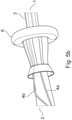
- Figure 5a illustrates the attachment of an advantageous embodiment of the contamination protection device according to the invention to the proximal end of the endoscope shaft 1. Shown are the proximal clamping bracket 93 on the seal 92 and the air and water hoses 4a, 4b, for which corresponding recesses are provided on the clamping bracket 93.
- the fabric hose 32 is shown at the top edge of the picture, which firmly encloses the endoscope shaft 1 together with the air and water hoses 4a, 4b running thereon and forms a base for the inner sleeve 3 to be unrolled.
- Figure 5c shows the form-fitting fixation of the inner and outer casing 3, 6 with the aid of the clamp 91, which presses the two casings onto the proximal clamping bracket 93 located underneath.
- the free ends of the inner and outer shell 3, 6 protruding beyond the clamp 91 are additionally held together by the clamp 94 and, for example, protected against unintentional tearing.
- the outer sleeve 6 is unrolled over the distal end of the shaft.
- proximal clamp 93 nor the distal clamp 96 have to be removed between two contamination-protected examinations. This means that the time required to prepare the endoscope for a further examination is advantageously shortened by the fact that after the contamination protection has been dismantled, the clamping brackets including the seals located underneath remain on the shaft and can be used to attach a further contamination protection.
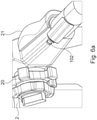
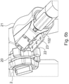
- the Figures 6a to 6c show partial steps of the attachment of an embodiment of the grip attachment 21 according to the invention. This is typically made in at least two parts, one part being an in Figure 6a illustrated ergonomically shaped handpiece 21, which is attached to the side of the handle 2 of the endoscope.
- valve holder 22 is characterized by receptacles for three valves
- instrument holder 23 forms a receptacle for the two-way hose distributor 24, which is arranged above the proximal instrument channel opening 102.
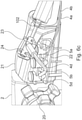
- Figure 6c shows the final assembly state.
- the three valves for air, water and suction 5a, 5b, 5c are inserted into the corresponding receptacles on the valve holder 22 and connected to the air and water hoses 4a, 4b coming from the distal end of the endoscope shaft 1 and the suction hose 4d.
- the hoses exiting the valves are connected to appropriate devices, by means of which the channels can be pressurized with overpressure, underpressure or water.
- the treating doctor can open the three valves 5a, 5b, 5d with the touch of a finger.
- these valves are inexpensive single-use products that are disposed of and changed after each examination.
- the y-shaped two-way tubing manifold 24 shown in the instrument holder 23 is inserted and is connected to the working tube 4c protruding from the proximal instrument channel opening 102.
- the suction hose 4d is connected to the laterally exiting distributor legs, the straight leg of the distributor serves as access for instruments 80 to be used in the course of the examination.
- the area between the distal end of the two-way hose distributor 24 and the proximal instrument channel opening 102, in which the working tube 4c is exposed, is provided for cutting through the working tube 4c in the course of disassembly after the endoscopy has taken place. Curling tongs should advantageously be used for the cutting, which fuses the two cut ends immediately in a germ-proof manner in order to prevent the contamination present in the working hose 4c from escaping.
- FIG. 7 shows an embodiment of the contamination protection device that is preassembled during production for quick and user-friendly attachment to the endoscope shaft 1.
- the aim here is to pull the device onto the shaft 1 in one piece.
- the inner casing 3 and outer casing 6 lie on top of each other and are rolled up together up to the cap 31.
- the air and water hoses 4a, 4b that open out into the front side of the cap 31 are wound up in a spiral, with the winding having a larger diameter than the shaft 1.
- Both hoses 4a, 4b are fixed to the clamp 94 and connected with their proximal ends to the air valve 5a and the water valve 5b.
- the proximal end of the working tube 4c which also ends distally in the end face of the cap 31, is inserted into the distal instrument channel opening 101 and the entire aforementioned structure is pushed over the shaft tip onto the shaft 1 until the cap 31 is on the previously mounted distal clamping bracket 96 snaps into place.
- the clamp 94 is pushed up over the proximal clamping bracket 93, which was likewise installed beforehand, and the inner sleeve 3 and outer sleeve 6 are unrolled in the process. Then only the proximal ends of the two sleeves 3, 6 have to be pushed into the clamp 94 and the clamp 91 closed around it for fixing and sealing in the area of the proximal clamping bracket 93.
- air valve 5a and water valve 5b are attached to the handle attachment 21 and the working hose protruding from the proximal instrument channel opening 102 can be connected to the two-way hose distributor 24 .
- a bracket-like clamp 33 is formed on the proximal end of the cap 31 .
- This is made of a suitably deformable plastic and can be bent around the endoscope shaft and fixed via the click fastener 331, 331'.
- Air hose opening 30a and water hose opening 30b are arranged in a tube shape in a web 332, which clamp 31 and clamp 33 connects.
- the advantage of this embodiment is its smaller diameter compared to the variant with a distal clamping bracket.
- the cap 31 shown with the clamp 33 can advantageously also be used accordingly in an embodiment of the contamination protection device that is preassembled on the production side Figure 7 find use.
- the distal end of the cap can also be made from an optically neutral shrink tubing.
- the objects described in claims 2 to 4 are shown, which serve to connect the distal end of the outer sleeve 6 to the patient.
- this is the diaper pants 7a according to the invention, which are used in colonoscopies.
- These diaper pants 7a are put on by the patient to be examined and have an opening with a connection part 71a, which is suitably positioned relative to the body opening to be examined, ie anus or enterostoma.
- the outer casing 6 can be connected to this connecting part 71a by means of the connecting piece 61a provided at its distal end in an advantageous embodiment, so that an airtight, watertight and germ-tight connection is created.
- the endoscope shaft 1 protected by the inner sleeve 3 is then pushed through the opening provided in the diaper pants 7a and inserted into the body opening of the patient to be examined.
- the intestinal contents or other body fluids that emerge during the examination are thus drained through the diaper pants 7a on the one hand and the on the other hand, the protective volume formed between the outer and inner shell 6, 3 is prevented from escaping into the examination environment.
- the teething ring 7b is used for gastroscopies, at the opening of which the connection part 71b is held up. This in turn serves to connect the outer shell 6 to the patient via the connecting piece 61b.
- the teething ring 7b can be expanded to include sections that enclose the face or at least the jaw area of the patient like a mask.
- a partition wall 7c with an opening and connection part 71c can be used, behind which the patient is positioned during the endoscopic examination.
- the attending physician acts from the front of the partition and is thus protected from direct contamination.
- the dividing wall 7c can take the form of a closed cabin, except for the lead-through opening, in which all contaminations conveyed out of the patient during the examination remain enclosed.
- FIG. 10 shows an embodiment of the endoscope according to the invention, in which a stretched film 7c is used as a separation between the patient and the attending physician.
- This film is provided with an opening to which the outer shell 6 is welded with its distal end, as a result of which an airtight, watertight and germ-tight connection is realized here.
- the separating film 7c should be dimensioned in such a way that it can be folded over and placed under the patient to be examined. As a result, all dirt that occurs during the examination is collected on the film and kept away from the rest of the examination environment, in particular the patient couch.
- FIG. 11 shows the instrument protection 8 according to the invention together with a performed instrument 80, which usually consists of a Micro device 80a consists of an instrument Bowden cable 80b and can be operated with the control element 80c.
- the instrument protection 8 consists of an instrument hose 81 pushed on here like a bellows, which is delimited at both ends by the instrument hose caps 82, on the end faces of which openings for the passage of the instrument 80 are provided.
- the instrument protection 8 is connected to the proximal end of the straight leg of the two-way hose distributor 24 in the illustrated folded state like a bellows.
- the instrument 80 In order to remove the soiled parts of the instrument 80 from the working hose 4c after the surgical intervention without releasing any contamination, it is drawn into the instrument hose 81, which is pulled out to its full length for this purpose.
- the length of the instrument hose 81 is accordingly to be dimensioned in such a way that the micro-device 80a together with the Bowden cable 80b can be completely encased by it.
- the instrument 80 After the instrument 80 has been pulled into the instrument protection 8, it can be removed from the two-way hose distributor 24, with all dirt being held back inside the instrument hose 81.
- Figures 12a to 12c show an advantageous embodiment of the working hose 4c according to the invention with a protective hose 4c1, which is conducive to contamination-protected disassembly.
- the working hose 4c has a predetermined breaking point 4c0, for example in the form of a circumferential notch.
- the protective hose 4c1 is connected to the outside of the working hose 4c in an airtight, watertight and germ-tight manner over the entire circumference, typically by a welded or adhesive connection.
- Figure 12b is shown how the protective hose after breaking the predetermined breaking point 4c0 by pulling on the two separate ends of the Working hose 4c is drawn in length, whereby it is finally torn.
- the polymeric material used for the protective hose 4c1 should have a significantly higher elongation at break than the material of the working hose 4c, so that the end sections torn apart as in Figure 12c are shown so strongly plastically deformed that they close the ends of the working hose 4c like a pocket and protect against the escape of contamination.
- figure 13 shows a perspective overall view of a further embodiment of the endoscope according to the invention with a contamination protection device, in which the two-way hose distributor is connected directly to the proximal instrument channel opening.
- the tubing manifold 24' connects directly to the proximal instrument channel opening 102.
- the air and water valves are combined in a single valve 5ab, which is used together with the suction valve 5d in holders provided for this purpose in the handle 2.
- the proximal end of the working hose 4c leading out of the proximal instrument channel opening 102 and the suction hose 4d leading to the suction valve 5d are connected to the two-way hose distributor 24'.
- the hoses for the compressed air 4a and the water supply 4b are wound around the shaft 1 to secure them and are routed to the combined air/water valve 5ab and connected there.
- figure 14 is the two-way hose distributor of the embodiment suitable for direct connection to the instrument channel opening figure 13 shown schematically in detail.
- the y-shaped two-way hose distributor 24' has three ends or connections.
- the distal end 241 which can in particular have a conical shape, can be inserted into the proximal end 242 of the working hose 4c led out of the instrumentation channel opening 102 .
- the suction tube 4d is connected to one of the two proximal ends, the other end 242 is open and serves as an instrument access.
- the hose distributor 24' is equipped with a ring nut 243, which is seated on the hose distributor 24' in an axially displaceable manner.
- a radially protruding collar 244 formed in the area of the distal end 241 interacts with a stop of the ring nut 243 in order to fasten the tube distributor to a corresponding connection means of the proximal instrument channel opening 102 after the ring nut has been fixed.
- the instrumentation channel opening 102 can have, for example, a widely used Luer lock connection.
- Figures 15A - D illustrate the procedure for the direct connection of a hose distributor suitable for this purpose of the embodiment according to FIG Figures 13 and 14 .
- the working hose 4c is pushed sufficiently far out of the proximal instrument channel opening 102. Then the two-way hose distributor 24' is connected with its distal end 41 by plugging it into the working hose, part figure B.
- the working hose 4c is designed here in such a way that the pressure forces exerted when the two-way hose distributor 24' is inserted the proximal end of the working hose is compressed like a bellows and the bellows section 4c' is thus formed.
- Subfigure C shows the step in which the ring nut 243 of the hose distributor 24' is connected to the proximal instrument channel opening with the aid of a connection means, here a Luer lock connection.
- the endoscope is ready for an examination or operation.
- the two-way hose distributor 24' is detached again and together with the working channel from the proximal instrument channel openings 102 is pulled away, as a result of which the bellows section 4c' of the working channel 4c unfolds again.
- the working hose can now be severed and sealed in one step with hot scissors and thus pulled distally out of the instrumentation channel without contamination.
- figure 16 shows a further embodiment of an endoscope according to the invention with two instrumentation channels and correspondingly two working hoses.
- the distal end of the shaft 1 shown in the left part of the figure has two distal instrument channel openings 101 into which a working hose 4c is to be pushed as part of the protection against contamination according to the invention.
- the two instrumentation channels of the endoscope shown here open proximally into two corresponding instrumentation channel openings 102, partial figure at the top right.
- the valve holders with valves 5ab for air and water and 5d for suction are also shown in this partial figure.
- the instrument channel openings 102 are shown closed with protective caps in the partial figure at the bottom right.
Landscapes
- Health & Medical Sciences (AREA)
- Life Sciences & Earth Sciences (AREA)
- Surgery (AREA)
- Nuclear Medicine, Radiotherapy & Molecular Imaging (AREA)
- Biomedical Technology (AREA)
- Optics & Photonics (AREA)
- Pathology (AREA)
- Radiology & Medical Imaging (AREA)
- Biophysics (AREA)
- Engineering & Computer Science (AREA)
- Physics & Mathematics (AREA)
- Heart & Thoracic Surgery (AREA)
- Medical Informatics (AREA)
- Molecular Biology (AREA)
- Animal Behavior & Ethology (AREA)
- General Health & Medical Sciences (AREA)
- Public Health (AREA)
- Veterinary Medicine (AREA)
- Endoscopes (AREA)
Description
- Die vorliegende Erfindung betrifft ein Endoskop mit Kontaminationsschutzvorrichtung Die medizinische Endoskopie ist ein diagnostisches Verfahren zur Untersuchung von Körperöffnungen oder -höhlen, bei dem auch die Möglichkeit zur Durchführung minimal invasiver operativer Eingriffe gegeben ist. Das Verfahren beruht darauf eine bildgebende Sonde in die zu untersuchende Körperöffnung einzuführen.
- Zu diesem Zweck werden Endoskope verwendet, welche aus einem Griffstück und einem daran anschließenden, starren oder flexiblen Schaft bestehen, an dessen Spitze Vorrichtungen zur Beleuchtung und Bildgebung vorgehalten sind. Zur Beleuchtung wird entweder das Licht einer außerhalb des Endoskops angeordneten Lichtquelle verwendet, das durch im Inneren des Endoskopschafts verlaufende Glasfaserbündel geleitet wird, oder, bei heutigen Endoskopen üblicher, durch in die Schaftspitze integrierte Lichtquellen, insbesondere LEDs, erzeugtes Licht eingesetzt. Zur Darstellung des Untersuchungsobjekts ist an der Schaftspitze eine Optik angeordnet, deren Bild bei Endoskopen modernster Bauart von einem Videochip registriert, weiterverarbeitet und über eine ebenfalls im Schaft verlaufende Datenleitung ausgelesen wird. Zur Manipulation des Untersuchungsobjektes, insbesondere zum dosierten Aufblähen von Hohlorganen und Körperhöhlen, ist an der Schaftspitze ferner eine Luftdüse vorgehalten, welche über einen im Inneren des Schafts verlaufenden Kanal von außerhalb des Endoskop angeordneten Pumpen oder Irrigatoren beaufschlagt werden kann.
- Des Weiteren befindet sich an der Schaftspitze eine abgewinkelt angeordnete Wasserdüse, welche während der Untersuchung zum Abspülen von Körpersekreten von der Schaftspitze verwendet wird, insbesondere um die bildgebende Optik zu reinigen. Auch die Wasserdüse wird über einen im Schaftinneren verlaufenden Wasserkanal versorgt.
- Außerdem weisen Endoskope üblicherweise einen durch den Schaft verlaufenden Instrumentierkanal auf, durch welchen mikromechanische Geräte wie Zangen, Greifer oder Schlingen an Bowdenzügen in den Untersuchungsraum geführt werden können, um bspw. eine Biopsie vorzunehmen.
- Zusätzlich kann der Instrumentierkanal auch zur Absaugung verwendet werden. Dazu mündet er an seinem proximalen Ende im Bereich des Griffstücks in einem y-förmigen Verteilerstück, welches über seine beiden proximalen Schenkel sowohl Zugänglichkeit für ein Instrument als auch eine Anschlussmöglichkeit für eine Pumpe bietet.
- Zur Bedienung durch den untersuchenden Arzt sind an dem Griffstück Ventile für Luft, Wasser und Absaugung vorgehalten sowie Bedienelemente zum Abwinkeln und Feinpositionieren der Schaftspitze, welche über im Schaft verlaufende Bowdenzüge angesteuert wird. Die Grobpositionierung des Schaftes in der zur untersuchenden Körperöffnung wird durch händisches Vorschieben oder Zurückziehen vorgenommen. Die Bedienung der Instrumentiermechanik erfolgt über ein separates, am proximalen Ende des Instruments vorgehaltenes Bedienelement.
- In der Praxis stellen die bei endoskopischen Untersuchungen auftretenden Kontaminationen mit Körperflüssigkeiten ein schwerwiegendes Problem dar. Solche Kontaminationen betreffen dabei so-wohl das Endoskop, die Untersuchungsumgebung, das medizinische Personal als auch, bei Verwendung eines nicht ausreichend sterilisierten Endoskops, den untersuchten Patienten selbst.
- Der Aufwand zur Reinigung und Sterilisation eines gebrauchten Endoskops ist beträchtlich: Er umfasst zahlreiche Arbeitsschritte des mechanischen Reinigens, des Spülens, der Anwendung von Enzymreinigern, des Desinfizierens und des Trocknens, und nimmt in der Praxis typischerweise einen Zeitaufwand von 45 Minuten in Anspruch. Diese Prozedur bedingt hohe Personal- und Gerätekosten und stellt einen entscheidenden Faktor in der Amortisationsdauer der in der Anschaffung kostspieligen Endoskope dar. Es findet dadurch ferner eine unerwünschte Kapitalbindung statt, da für die Gewährleistung eines kontinuierlichen Untersuchungsbetriebes eine Vielzahl an Endoskopen vorgehalten werden muss.
- Neben diesen ökonomischen Aspekten stellt insbesondere das Kontaminationsrisiko für das die Endoskopie durchführende, medizinische Personal ein schwerwiegendes Problem dar. So kommt der behandelnde Arzt durch das händische Verschieben des Endoskopschafts im Zuge der Untersuchung unweigerlich mit Körperflüssigkeiten in Kontakt. Auch bei der Instrumentenentnahme aus dem verschmutzten Instrumentierkanal ist das Kontaminationsrisiko evident. Ebenso ist die im Zuge der Untersuchung entstehende Verschmutzung der Untersuchungsumgebung, insbesondere der Patientenliege, zu beachten.
- Im Stand der Technik sind Kontaminationsschutzvorrichtungen für medizinische Endoskope bekannt. So beschreibt die Patentschrift
EP1578255B1 eine Schutzhülle aus einem elastischen Material, welche ausgehend von seiner Spitze kondomartig über den Endoskopschaft gezogen wird. Diese Hülle besteht dabei zumindest im Bereich der Endoskopoptik aus einem optisch transparenten Material, um die endoskopische Bildgebung nicht zu beeinträchtigen. Da bei Verwendung einer solchen Schutzhülle die im Inneren des Endoskopschafts verlaufenden Arbeitskanäle nicht mehr zugänglich sind, lehrt die Patentschrift separate Luft-, Wasser- und Instrumentierkanäle vorzuhalten, die zwischen Endoskopschaft und Schutzhülle anzuordnen sind und am distalen Ende luft-, wasser- und keimdicht mit der Schutzhülle verbunden sind. Bei Verwendung einer solchen Schutzvorrichtung nach dem Stand der Technik lässt sich eine direkte Kontamination des Endoskops während der Untersuchung vermeiden. - Ungelöst bleibt jedoch das Problem der Kontamination des medizinischen Personals und der Untersuchungsumgebung, woraus in weiterer Folge auch eine indirekte Kontamination des Endoskops resultieren kann. Nachteilig ist außerdem, dass durch Verwendung eines separaten, außenliegenden Instrumentierkanals, welcher üblicherweise einen nicht unbeträchtlichen Durchmesser aufweist, eine signifikante Vergrößerung des Gesamtquerschnitts des Endoskops einhergeht, wodurch die endoskopische Untersuchung für den Patienten mit erhöhten Schmerzen verbunden sein kann bzw. bestimmte kleinräumige Untersuchungsbereiche gar nicht mehr zugänglich sind.
- Die vorliegende Erfindung möchte vor diesem Hintergrund die Aufgabe lösen, einen verlässlichen und umfassenden Kontaminationsschutz für endoskopische Untersuchung zu gewährleisten, welcher Verschmutzung des Endoskops, der Untersuchungsumgebung und des medizinischen Personals drastisch reduziert oder vermeidet, dabei aber zu keinerlei Einschränkung von Handhabbarkeit und Verwendbarkeit des Endoskops führt.
- Erreicht wird dies durch ein Endoskop mit Kontaminationsschutzvorrichtung gemäß einem der Ansprüche 1 - 13, welche gemäß einem der Ansprüche 14-18 angebracht werden kann.
- Die wesentliche Idee der vorliegenden Erfindung besteht dabei darin, zwischen der zu untersuchenden Körperöffnung des Patienten und dem proximalen Ende des eingeführten Endoskopschafts ein Schutzvolumen vorzuhalten, welches alle im Zuge der Untersuchung freiwerdenden Körperflüssigkeiten aufsammelt und von Kontakt mit der Umgebung fernhält. Dieses Volumen wird begrenzt durch eine Innenhülle, welche im Wesentlichen der im Stand der Technik beschriebenen Schutzhülle auf dem Endoskopschaft entspricht, sowie durch eine größer dimensionierte Außenhülle, die am proximalen Ende der Innenhülle an selbiger luft-, wasser- und keimdicht befestigt ist. Während der endoskopischen Untersuchung wird lediglich die Innenhülle in die zu untersuchende Körperöffnung eingeführt, so dass alle beim Herausziehen des Endoskopschafts an der Innenhülle anhaftenden Körperflüssigkeiten oder sonstige Verschmutzungen von der Außenhülle schützend bedeckt werden.
- Im Weiteren werden vorteilhafte Ausführungen des erfindungsgemäßen Endoskops mit Kontaminationsvorrichtung vorgestellt, welche in geeigneter Form miteinander kombiniert werden können.
- Um das erfindungsgemäß durch Außen- und Innenhülle aufgespannte Schutzvolumen vollständig von der Untersuchungsumgebung abzuschließen, sind am distalen Ende der Außenhülle geeignete Mittel vorzuhalten. Diese bestehen aus Anschlussstücken, welche mit patientenseitig vorgehaltenen, erfindungsgemäßen Vorrichtungen verbunden werden können.
- Für koloskopische Untersuchung des Darmes wird eine solche Vorrichtung durch eine spezielle Windelhose für den zu untersuchenden Patienten dargestellt, die eine Öffnung mit einem Aufnahmeteil aufweist, an welches das Anschlussstück der Außenhülle luft-, wasser- und keimdicht angeschlossen werden kann. Auf diese Weise wird das Schutzvolumen um einen Abschnitt der Windelhose erweitert und bei passgenauem, dichtem Sitz der Windelhose am Patienten von der Untersuchungsumgebung im Wesentlichen abgeschlossen.
- In Analogie dazu kann bei gastroskopischen Untersuchungen der Speiseröhre oder des Magens ein geeigneter Beißring für die Aufnahme des Anschlussstückes der Außenhülle verwendet werden, an dem ein erfindungsgemäßes Anschlussteil angeformt ist. Um eine Kontamination der Außenseite der Außenhülle durch aus den Mundwinkeln des Patienten austretende Körperflüssigkeiten zu vermeiden, kann ein solcher Beißring maskenartig um die Kieferpartie erweitert werden, wobei dafür Sorge zu tragen ist, dass damit keine signifikante Beeinträchtigung der Atemtätigkeit des Patienten einhergeht.
- Alternativ kann eine geeignete dimensionierte Trennwand zwischen den zu Patienten und das die Untersuchung durchführende, medizinische Personal positioniert werden. An dieser ist erfindungsgemäß eine relativ zur Patientenliege passend angeordnete Öffnung vorzuhalten, die mit einem Aufnahmeteil zur Verbindung mit dem Anschlussstück der Außenhülle versehen ist. Mit einem solchen Aufbau wird zwar die unmittelbare Untersuchungsumgebung, insbesondere die Patientenliege, Verschmutzungen während der Untersuchung ausgesetzt, nicht aber das auf der anderen Seite der Trennwand befindliche medizinische Personal. Durch geeignete Ausgestaltung der Trennwand, insbesondere in Form einer Kabine, kann das kontaminierte Volumen weiter eingeschränkt bzw. ganz abgeschlossen werden.
- Die Verbindung von Anschlussteil und -stück soll in allen vorgenannten Ausführungsformen luft-, wasser- und keimdicht ausgeführt sein und gesichert gegen unbeabsichtigtes Öffnen während der Durchführung der Endoskopie. Zu diesem Zweck sind geeignete Schraub-, Steck-, Klemm- oder Magnetverbindungen bekannt.
- Als zusätzliche Schutzmaßnahme kann die Außenhülle noch über das proximale Ende der Innenhülle hinausgeführt werden und auch das Griffstück des Endoskops samt Griffaufsatz schützend umhüllen.
- Innen- und Außenhülle sollte aus einem für medizinische Zwecke üblicherweise verwendeten Material bestehen, welches luft- und wasserdicht ist sowie undurchlässig für Krankheitskeime. Es muss ferner ein ausreichendes Maß an Widerstandsfähigkeit gegen mechanischen Verschleiß wie Reißen oder Abrasion aufweisen, sowie chemische Beständigkeit gegen im Zuge von endoskopischen Untersuchungen anzutreffende Substanzen, bspw. Säuren oder Fette. Zum Zwecke der Montage sollten Innen- und Außenhülle insbesondere leicht aufrollbar sein. Als geeignete polymere Werkstoff kommen bspw. Polybuten (PB) oder Cycloolefin-Polymere (COP) in Frage.
- Zum Kontaminationsschutz des im Inneren des Endoskopschafts verlaufenden Instrumentierkanals lehrt vorliegende Erfindung in vorteilhafter Ausführung die Verwendung eines Arbeitsschlauchs, der den Instrumentierkanal auf seiner ganzen Länge auskleidet und hinter dem proximalen Ende des Schaftes aus der Instrumentierkanalöffnung herausragt, die bei handelsüblichen Endoskopen ohne Kontaminationsschutz zum Einführen der Instrumente dient, d.h. nicht der Absaugung. Am distalen Ende der Innenhülle mündet der Arbeitsschlauch stirnseitig in einer Arbeitsschlauchöffnung, an die er nahtlos angeformt ist.
- Um den Arbeitsschlauch sowohl zur Gerätedurchführung als auch zur Absaugung verwenden zu können, mündet er erfindungsgemäß hinter der proximalen Instrumentierkanalöffnung in einem y-förmigen Zwei-Wege-Schlauchverteiler, der in eine passende Aufnahme am Halter eines Griffaufsatzes eingesteckt oder alternativ direkt an der proximalen Instrumentierkanalöffnung befestigt ist.
- Der Griffaufsatz der ersten Variante kann weiterhin Befestigungen für die Ventile, also das Luftventil, Wasserventil und das Absaugventil umfassen. In der zweiten Variante wird vorgeschlagen, den Schlauchverteiler mittels einer axial verschiebbar aufgesetzten Ringmutter auszustatten, mit welcher der Schlauchverteiler lösbar an dem üblicherweise vorhandenen Luerlock-Anschluss des proximalen Instrumentierkanalendes befestigbar ist.
- Der Arbeitsschlauch mündet im distalen Ende dieses Schlauchverteilers, so dass er durch einen der beiden proximalen Schenkel des Schlauchverteilers für ein Instrument und durch den anderen zur Absaugung zugänglich ist.
- Die Absaugung wird dabei in der ersten Variante über ein ebenfalls am Halter des Griffaufsatzes vorgehaltenes Saugventil kontrolliert, das über einen Saugschlauch mit einem proximalen Ende des Zwei-Wege-Schlauchverteilers verbunden ist.
- Für Endoskope mit mehr als einem Instrumentierkanal, bekannt sind beispielsweise Endoskope mit zwei Instrumentierkanälen, kann der erfindungsgemäße Kontaminationsschutz auch mehr als einen Arbeitsschlauch, insbesondere jeweils einen Arbeitsschlauch pro Instrumentierkanal des Endeskops, aufweisen.
- Ebenfalls können mehr als ein Wasser- oder Luftschlauch vorhanden sein. Es sind beispielsweise Endoskope mit einem zusätzlichen Wasserkanal bekannt, auch als Jet-Kanal bezeichnet, welcher in der Endoskopspitze frei mündet und nicht zur Spülung der Optik gedacht ist, sondern dazu, die Operations- oder Untersuchungsstelle mit Wasser zu spülen. Für solche Endoskope kann der erfindungsgemäße Kontaminationsschutz um einen weiteren Wasserschlauch samt Ventil ergänzt werden. Alternativ kann der Wasserschlauch auch doppellumig sein, wobei ein Lumen zur Spülung der Optik und das andere als Jet-Kanal verwendet wird.
- Auf diese Weise wird ein inwendiger Kontaminationsschutz des Endoskopschafts realisiert, welcher eine uneingeschränkte Verwendung des Instrumentierkanals zur Durchführung mikromechanischer Geräte und zur Absaugung ermöglicht.
- In einer weiteren Ausführungsform, bei der die Außenhülle als redundante Schutzmaßnahme hinter dem proximalen Schaftende weitergeführt wird und Griffstück und -aufsatz umhüllt, ist der Zwei-Wege-Schlauchverteiler in die Außenhülle integriert, also etwa luft-, wasser- und keimdicht daran angeschweißt.
- In einer weiteren vorteilhaften Ausführungsform ist an dem zum Einführen eines Instrumentes vorgesehenen, proximalen Ende des Zwei-Wege-Schlauchverteilers ein erfindungsgemäßer Instrumentenschutz angeschlossen. Dieser dient dazu, das nach Abschluss des Instrumentiervorgangs aus dem Arbeitskanal her-ausgezogene Instrument samt zugehöriger Bowdenzüge und etwaig entnommener Gewebeprobe in einen schützenden Instrumentenschlauch einzuziehen und somit medizinisches Personal und Untersuchungsumgebung vor Kontakt mit anhaftenden Verschmutzungen zu bewahren. Die Länge dieses Instrumentenschlauchs ist folglich größer als die Länge des Arbeitsschlauches zu dimensionieren, so dass der gesamte verschmutzte Abschnitt des Instruments und der Bowdenzüge darin Platz findet. Die beiden Enden des Instrumentenschlauchs sind mit je einer Kappe mit stirnseitiger Öffnung versehen, welche der Verbindung mit dem Zwei-Wege-Schlauchverteiler bzw. einem Griffstücks des Instruments dienen. Der Instrumentenschlauch sollte aus einem balgartig zusammenschiebbarem Material bestehen, so dass sich der gesamte Instrumentenschutz auf ein kleines Maß zusammen-drücken lässt, was eine übersichtliche und kompakte Anbringung am Griffansatz gewährleistet.
- Zur Befestigung der Innenhülle an der Spitze des Endoskopschafts lehrt vorliegende Erfindung den distalen Endabschnitt der Innenhülle vorteilhaft in Form einer steifen Kappe auszuführen, die auf einen Klemmbügel gesteckt wird, welcher die Mantelfläche des Endoskopschafts umfasst.
- Die Steckverbindung kommt dadurch zustande, dass eine den Klemmbügel umlaufende Feder in eine entsprechende Nut an der Innenseite der Kappe einrastet. Um die Kappe einfach und schnell wieder lösen zu können, kann an ihr ein sich über einen Teil des Schaftumfangs erstreckender bügelartiger Klemmer angeformt sein, mittels dessen bei entsprechender Kraftausübung der Umfang der offenen Stirnseite der elastischen Kappe soweit erweitert werden kann, dass sie sich wieder von der Feder des Klemmbügels lösen und von der Schaftspitze abziehen lässt.
- Alternativ kann die Kappe auch ohne Verwendung eines Klemmbügels mit Hilfe an der offenen Stirnseite der Kappe angeformte, axial verlaufende elastische Branchen auf die Schaftspitze geklemmt werden.
- Zur platzsparenden Durchführung von Luft- und Wasserschläuchen sollte die Feder entsprechende Aussparungen aufweisen, und die Schläuche in vorteilhafter Ausführungsform in das Kappeninnere geführt werden und in Öffnungen auf der Stirnfläche münden.
- Der die Kappe fixierende Klemmbügel sollte von einer Dichtung unterlegt sein, die bspw. aus Silikon, Teflon, EPDM Kautschuk oder einem selbstklebenden Adhäsiv bestehen kann.
- In weiterer vorteilhafter Ausführung sind Innen- und Außenhülle am proximalen Ende des Endoskopschafts befestigt. Dazu kann ein weiterer von einer Dichtung unterlegter Klemmbügel dienen, auf welchem Innen- und Außenhülle aufliegen und von einer umlaufenden Klemme fixiert werden.
- Weder der proximale noch der distale Klemmbügel müssen zwischen zwei kontaminationsgeschützten Untersuchungen abgenommen werden, wodurch die zur Vorbereitung des Endoskops für eine weitere Untersuchung benötigte Zeit vorteilhaft verkürzt wird.
- Es ist ferner vorteilhaft Innen - und Außenhülle derart einteilig zu fertigen, dass sie am proximalen Ende der Innenhülle miteinander verbunden sind. Eine solche Verbindung kann in der Fertigung bspw. durch ein Schweißverfahren realisiert werden, etwa das zur Verbindung von polymeren Werkstoffen geeignete Ultraschall-Schweißen. Dadurch wird eine potentielle Schwachstelle bzgl. der Dichtheit der Schutzvorrichtung eliminiert und die Anbringung der Hüllen auf dem Endoskopschaft erleichtert. Zur handlicheren Anbringung bzw. Demontage der Kontaminationsschutzvorrichtung kann die Innenhülle entlang des Endoskopschafts vorteilhaft von einem flexiblen Gewebeschlauch unterlegt werden.
- Die zu Anbringung und Demontage der erfindungsgemäßen Kontaminationsschutzvorrichtung an ein Endoskop notwendigen Schritte werden nachstehend im Rahmen der Figurenbeschreibung detailliert angegeben.
- Bei der Verwendung eines erfindungsgemäßen Endoskops ist es vorteilhaft, die Kontaminationsschutzvorrichtung auf Dichtheit zu überprüfen. Eine solche Dichtheitsprüfung kann zum einen nach erfolgter Anbringung der Vorrichtung am Endoskop erfolgen, um ggfs. Material- und Montagefehler zu entdecken.
- Ein geeignetes Verfahren der Dichtheitsprüfung wäre bspw. die Differenzdruck-Methode. Das distale Ende der Außenhülle mit dem ggfs. daran angeformten Anschlussstück ist an das Prüfgerät anzuschließen, so dass die Dichtheitsprüfung dem zwischen Innen- und Außenhülle aufgespannten Schutzvolumen gilt. Dazu ist es außerdem notwendig Luft- und Wasserschlauch abzudichten, bspw. durch geeignete Stöpsel.
- Bei Verwendung einer Ausführungsform der Kontaminationsschutzvorrichtung mit Arbeitsschlauch sollte ein solcher Abdichtstöpsel in das proximale Schlauchende eingesteckt werden, so dass im Zuge der Dichtheitsprüfung auch der vom Arbeitsschlauch ausgekleidete Instrumentierkanal im Endoskopschaft überprüft wird.
- Es ist ferner vorteilhaft, auch nach Abschluss der endoskopischen Untersuchung eine entsprechende Dichtheitsprüfung vorzunehmen. Dadurch kann überprüft werden, ob das Endoskop im Zuge der Untersuchung kontaminiert worden ist und entsprechende Reinigungsmaßnahmen vor der nächsten Verwendung durchzuführen sind. Vor der Dichtheitsprüfung sind die Außenhülle an ihrem distalen Ende sowie Luft-, Wasser- und ggfs. Arbeitsschlauch im Bereich des Griffstücks derart zu durchtrennen, dass die abgetrennten Enden luftdicht verschlossen sind. Dies kann bspw. mittels einer Brennschere geschehen.
- Bei Verwendung einer Ausführungsform der Kontaminationsschutzvorrichtung mit einteilig gefertigter Innen- und Außenhülle kann die an die Untersuchung anschließende Dichtheitsprüfung auch an der bereits demontierten Kontaminationsschutzvorrichtung vorgenommen werden.
- Als Zugang für das Dichtheitsprüfgerät zum kontaminierten Volumen der Kontaminationsschutzvorrichtung sollte in vorteilhafter Ausführungsform das proximale Ende des Arbeitsschlauchs verwendet werden, welches zu diesem Zwecke neuerlich geöffnet werden muss. Ist in einer einfacheren Ausführungsform der Kontaminationsschutzvorrichtung kein Arbeitsschlauch vorhanden, so kann als Zugang stattdessen eine neuerliche Öffnung in die Außenhülle geschnitten werden.
- Weitere Eigenschaften, Merkmale und Vorteile vorliegender Erfindung ergeben sich aus der im Folgenden anhand der Figuren näher erläuterten, beispielhaften Ausführungen. Diese sollen vorliegende Erfindung nur illustrieren und in keiner Weise einschränken.
- Es zeigen:
- Figur 1:
- Gesamtansicht eines erfindungsgemäßen Endoskops
- Figur 2:
- Detailansicht der Spitze eines erfindungsgemäßen Endoskops
- Figur 3a-d:
- Anbringung des distalen Klemmbügels
- Figur 4a,b:
- Anbringung des distalen Endes der Innenhülle
- Figur 5a-c:
- Anbringung der Kontaminationsschutzvorrichtung am proximalen Schaftende
- Figur 6a-c:
- Anbringung der Kontaminationsschutzvorrichtung am Griffstück
- Figur 7:
- Vorteilhafte Ausführungsform zur bedienerfreundlichen Anbringung der Schutzvorrichtung an den Schaft
- Figur 8:
- Vorteilhafte Ausführungsform einer Kappe mit Klickverschluss
- In der Patentschrift
US 4,907,395 wird ein System zum Packen von Wegwerf-Endoskophüllen vorgeschlagen, welches sicherstellt, dass die Endoskophüllen während dem Transport, der Lagerung und dem Aufziehen auf ein Endoskop nicht kontaminiert werden und weiterhin auch die Verbreitung von der benutzten Hülle ausgehender Kontamination unterbindet. - Die internationale Veröffentlichungsschrift
WO 2009/086396 A1 beschreibt eine Hülle für ein Endoskop mit einer Kappe, welche auf das distale Ende des Endoskopschaftes aufsetzbar ist, und einem an der Kappe befestigten aufgerollten, flexiblen, länglichen Schlauch, welche nach dem Aufsetzen der Kappe entlang des Endoskopschaftes abrollbar ist. - Die vorliegende Erfindung möchte vor diesem Hintergrund die Aufgabe lösen, einen verlässlichen und umfassenden Kontaminationsschutz für endoskopische Untersuchung zu gewährleisten, welcher Verschmutzung des Endoskops, der Untersuchungsumgebung und des medizinischen Personals drastisch reduziert oder vermeidet, dabei aber zu keinerlei Einschränkung von Handhabbarkeit und Verwendbarkeit des Endoskops führt.
- Erreicht wird dies durch ein Endoskop mit Kontaminationsschutzvorrichtung gemäß einem der Ansprüche 1 - 13, welche gemäß einem der Ansprüche 14 - 18 angebracht werden kann.
- Die wesentliche Idee der vorliegenden Erfindung besteht dabei darin, zwischen der zu untersuchenden Körperöffnung des Patienten und dem proximalen Ende des eingeführten Endoskopschafts ein Schutzvolumen vorzuhalten, welches alle im Zuge der Untersuchung freiwerdenden Körperflüssigkeiten aufsammelt und von Kontakt mit der Umgebung fernhält. Dieses Volumen wird begrenzt durch eine Innenhülle, welche im Wesentlichen der im Stand der Technik beschriebenen Schutzhülle auf dem Endoskopschaft entspricht, sowie durch eine größer dimensionierte Außenhülle, die am proximalen Ende der Innenhülle an selbiger luft-, wasser- und keimdicht befestigt ist. Während der endoskopischen Untersuchung wird lediglich die Innenhülle in die zu untersuchende Körperöffnung eingeführt, so dass alle beim Herausziehen des Endo-skopschafts an der Innenhülle anhaftenden Körperflüssigkeiten oder sonstige Verschmutzungen von der Außenhülle schützend bedeckt werden.
- Im Weiteren werden vorteilhafte Ausführungen des erfindungsgemäßen Endoskops mit Kontaminationsvorrichtung vorgestellt, welche in geeigneter Form miteinander kombiniert werden können.
in die zu untersuchende Körperöffnung eines Patienten eingeführten Teils des Endoskops gewährleistet, die dadurch vervollständigt wird, dass der im Inneren des Endoskopschafts 1 verlaufende Instrumentierkanal 10 von dem an die Arbeitskanalöffnung 30c anschließenden Arbeitskanal ausgekleidet ist. Der so versiegelte Endoskopschaft wird von der Außenhülle 6 umhüllt, sodass der Zwischenraum ein Schutzvolumen bildet, in dem während der endoskopischen Untersuchung aus der Körperöffnung des Patienten austretende Körperflüssigkeiten aufgefangen werden. Patientenseitig wird dieses Schutzvolumen abgedichtet durch das an der Außenhülle 6 vorgehaltene Anschlussstück 61, welches beispielsweise an eine geeignete Windelhose 7a oder einen Beißring 7b angeschlossen werden kann. Die Abdichtung des Schutzvolumens am proximalen Ende des Endoskopschafts 1 wird in der inFig. 1 dargestellten Ausführungsform durch die Klemme 91 gewährleistet, welche Innen- und Außenhülle 3, 6 auf einen darunter befindlichen proximalen Klemmbügel 93 presst. Die darüber hinaus stehenden Enden von Innen- und Außenhülle 3, 6 werden in die Klammer 94 aufgenommen und somit bspw. gegen Einreißen gesichert. Zur Durchführung von Luft- und Wasserschläuchen 4a, 4b über das proximale Ende des Schutzvolumens hinaus sind in dem unter Klemme 91, Außen- und Innenhülle 6, 3 befindlichen proximalen Klemmbügel 93 entsprechende Schlitze vorgehalten. An das Griffstück 2 des Endoskops ist der Griffaufsatz 21 mit dem Ventilhalter 22 und dem Instrumentierhalter 23 aufgesetzt, in welche Luft-Wasser- und Saugventil 5a, 5b, 5d sowie der Zwei-Wege-Schlauchverteiler 24 eingesteckt sind. Der Zwei-Wege-Schlauchverteiler 24, der mit seinem distalen Ende an den aus der proximalen Instrumentierkanalöffnung 102 herausragenden Arbeitsschlauch 4c angeschlossen ist, ermöglicht über seine beiden proximalen Enden Zugang zum Instrumentierkanal 10. Der proximale Schenkel des Schlauchverteilers 24, welcher die geradlinige Verlängerung des distalen Schenkels bildet, ist für ein an einem Bowdenzug durchgeführtes Instrument 80 vorgesehen, mittels dem minimal invasive operative Eingriffe und Biopsien durchgeführt werden können. An den abgewinkelten Schenkel des Schlauchverteilers 24 sind der Saugschlauch 4d und das zugehörige Saugventil 5d angeschlossen. Luft- und Wasserventil 5a, 5b sind mit den zum distalen Ende des Endoskopschafts führenden Luft- und Wasserschläuchen 4a, 4b verbunden. Die aus den Ventilen 5a, 5b, 5d vom Endoskop weglaufenden Schläuche sind mit geeigneten, im Rahmen vorliegender Erfindung nicht beanspruchten Vorrichtungen zur Beaufschlagung mit Unter- oder Überdruck oder Wasser verbunden. -
Fig. 2 zeigt eine Detailansicht des distalen Endes einer vorteilhaften Ausführungsform des erfindungsgemäßen Endoskops. Unter der optisch transparenten Stirnseite 30 der Innenhülle 3 bzw. der Kappe 31 befinden sich die Beleuchtungsvorrichtungen 12, die zur Bildgebung dienende Optik 11 sowie die Düse 13, die bei erfindungsgemäßer Verwendung des Endoskops nicht betrieben wird. Die Stirnseite 30 wird durchstoßen von dem Luftschlauch 4a, welcher in der Luftschlauchöffnung 30a mündet, dem Wasserschlauch 4b mit der Wasserschlauchöffnung 30b, sowie dem im Instrumentierkanal 10 verlaufenden Arbeitsschlauch 4c mit der Arbeitsschlauchöffnung 30c. Ferner ist inFig. 2 der distale Klemmbügel 96 zu sehen, welcher von der distalen Dichtung 95 unterlegt die Mantelfläche des Endoskopschafts 1 umschließt und als Aufnahme für die darauf aufgesteckte Kappe 31 fungiert. - Anhand der
Fig. 3 bis 6 sollen Details einer besonders vorteilhaften Ausführungsform des erfindungsgemäßen Endoskops dargestellt und die zur Anbringung der Kontaminationsschutzvorrichtung notwendigen Schritte illustriert werden. - Die
Fig. 3a bis 3d zeigen die Montage eines Klemmbügels 96 am distalen Ende des Endoskopschafts 1. Um einen korrekten Sitz der darauf anzubringenden Kappe 31 zu gewährleisten, sind bei der Montage des Klemmbügels 96 sowohl seine axiale als auch seine radiale Positionierung auf der Mantelfläche des Endoskopschafts 1 von Bedeutung. Es muss gewährleistet sein, dass die Stirnseite 30 der Kappe 31 derart von der Stirnseite des Endoskopschafts beabstandet ist, dass einerseits keine signifikante Einschränkung des Blickwinkels der Endoskopoptik 11 hervorgerufen wird, andererseits aber ausreichender Platz besteht um Luft- und Wasserschläuche 4a, 4b von der Außenseite des Endoskopschafts 1 an die Stirnseite 30 der Kappe 31 heranzuführen. Des Weiteren muss gewährleistet sein, dass die in vorteilhafter Ausführungsform auf der Stirnseite 30 der Kappe 31 angeordnete Arbeitsschlauchöffnung 30c in Deckung vor die Instrumentierkanalöffnung 101 an der Stirnseite des Endoskopschafts gesetzt wird. Ferner dürfen die Luft- und Wasserschlauchöffnungen 30a, 30b nicht die Beleuchtungsvorrichtungen 12 an der Schaftspitze bedecken oder abschatten. Vorliegende Erfindung lehrt daher die vorteilhafte Verwendung einer Positionierhilfe 960 für die Montage des Klemmbügels 96, wie inFig. 3a bis 3d illustriert. Die Positionierhilfe 960 ist mit dem Klemmbügel 96 über Sollbruchstellen verbunden und wird nach erfolgter Montage abgebrochen. Die wesentlichen Elemente der Positionierhilfe 960 sind ein auf ihrer Stirnseite angeordneter und ins Innere weisender Zapfen, welcher in die Instrumentierkanalöffnung 101 eingesetzt wird, sowie eine stirnseitige Öffnung, welche über die aus der Schaftspitze herausragende Düse 13 gelegt wird. Dadurch ist die radiale Orientierung der Positionierhilfe samt daran befestigtem Klemmbügel eindeutig festgelegt, und es ist gewährleistet, dass die zur Durchführung von Luft- und Wasserschläuchen 4a, 4b vorgesehenen Aussparungen in der den Klemmbügel umlaufenden Feder im eingangs beschriebenen Sinne korrekt positioniert sind. Die axiale Position des Klemmbügels 96 wird dadurch festgelegt, dass die Positionierhilfe 960 formschlüssig an die Stirnfläche der Schaftspitze angedrückt wird. - Klemmbügel 96 und Positionierhilfe 960 sind vorteilhaft jeweils zweiteilig ausgeführt, und die Verbindung der beiden Klemmbügelhälften kommt durch ein klammerartiges Einrasten zustande.
-
Fig. 4a zeigt eine Detailansicht des distalen Endes des Endoskopschafts 1 während der Montage einer Ausführungsform erfindungsgemäßer Kontaminationsschutzvorrichtung. Die Innenhülle 3 ist dabei zunächst bis an die Kappe 31 aufgerollt. Der Arbeitsschlauch 4c wird in den Instrumentierkanal 10 im Endoskopschaft 1 eingeführt und der hier nicht wiedergegebene Luft- und Wasserschlauch 4a, 4b werden an der Außenseite des Schaftes 1 verlegt. Die distale Dichtung 95 und der distale Klemmbügel 96 sind wie unterFig. 3a bis 3d illustriert um den Endoskopschaft 1 montiert. -
Figur 4b zeigt eine Ansicht derselben Montagesituation aus entgegengesetzter Perspektive. Darin ist die in die Kappe 31 eingeprägte Nut zu erkennen, in welche die den Klemmbügel 96 umlaufende Feder zum Zwecke der Verbindung einrastet. -
Fig. 5a illustriert die Anbringung einer vorteilhaften Ausführungsform erfindungsgemäßer Kontaminationsschutzvorrichtung am proximalen Ende des Endoskopschafts 1. Dargestellt sind der proximale Klemmbügel 93 auf der Dichtung 92 sowie die Luft- und Wasserschläuche 4a, 4b, für deren Durchführung entsprechende Aussparungen am Klemmbügel 93 vorgehalten sind. Am oberen Bildrand ist der Gewebeschlauch 32 dargestellt, welcher den Endoskopschaft 1 samt daran verlaufender Luft- und Wasserschläuche 4a, 4b fest umhüllt und eine Unterlage für die abzurollende Innenhülle 3 bildet. - In
Fig. 5b ist die Innenhülle 3 vollständig über den Endoskopschaft 1 abgerollt worden, derart, dass sie auch den proximalen Klemmbügel 93 überdeckt. Des Weiteren ist die Außenhülle 6 im aufgerollten Zustand über die Innenhülle 3 hochgeschoben worden, ebenfalls bis zum proximalen Klemmbügel 93. Bei Verwendung einer solchen Ausführungsform, bei der Innen- und Außenhülle 3, 6 einteilig gefertigt, d.h. etwa miteinander verschweißt sind, vereinfacht sich die Montage dadurch, dass die Außenhülle 6 nicht separat über die Innenhülle 3 bis zum proximalen Schaftende hochgeschoben werden muss, sondern dies bereits während des Abrollens der Innenhülle 3 geschieht. -
Fig. 5c zeigt die formschlüssige Fixierung von Innen- und Außenhülle 3, 6 mit Hilfe der Klemme 91, welche die beiden Hüllen auf den darunter befindlichen proximalen Klemmbügel 93 presst. Die über die Klemme 91 hinausstehenden freien Enden von Innen- und Außenhülle 3, 6 werden zusätzlich durch die Klammer 94 zusammengehalten und bspw. gegen unbeabsichtigtes Einreißen geschützt. Im Anschluss an die derartige Fixierung am proximalen Schaftende wird die Außenhülle 6 bis über das distale Schaftende abgerollt. - Weder der proximale Klemmbügel 93 noch der distale Klemmbügel 96 müssen zwischen zwei kontaminationsgeschützten Untersuchungen abgenommen werden. D.h. die Zeit, die zur Vorbereitung des Endoskops für eine weitere Untersuchung benötigt wird, ist vorteilhaft dadurch verkürzt, dass nach der Demontage des Kontaminationsschutzes die Klemmbügel samt darunter befindlicher Dichtungen auf dem Schaft verbleiben und zur Befestigung eines weiteren Kontaminationsschutzes verwendet werden können.
- Die
Fig. 6a bis 6c zeigen Teilschritte der Anbringung einer Ausführungsform des erfindungsgemäßen Griffaufsatzes 21. Dieser ist typischerweise mindestens zweiteilig gefertigt, wobei das eine Teil ein inFig. 6a abgebildetes ergonomisch geformtes Handstück 21 darstellt, welches seitlich an das Griffstück 2 des Endoskops angesetzt wird. - Diesem gegenüber wird in
Fig. 6b ein Teil mit Ventilhalter 22 und Instrumentierhalter 23 als Gegenstück aufgesetzt und mit dem Griffstück 21 verbunden, etwa über eine Klickverbindung. Der Ventilhalter 22 ist gekennzeichnet durch Aufnahmen für drei Ventile, der Instrumentierhalter 23 bildet eine Aufnahme für den Zwei-Wege-Schlauchverteiler 24, der oberhalb der proximalen Instrumentierkanalöffnung 102 angeordnet wird. -
Fig. 6c zeigt den finalen Montagezustand. Die drei Ventile für Luft, Wasser und Absaugung 5a, 5b, 5c sind in die entsprechenden Aufnahmen am Ventilhalter 22 eingesetzt und mit den vom distalen Ende des Endoskopschafts 1 kommenden Luft- und Wasserschläuchen 4a, 4b sowie dem Saugschlauch 4d verbunden. Die aus den Ventilen auslaufenden Schläuche werden mit entsprechenden Vorrichtungen verbunden, mittels derer die Kanäle mit Überdruck, Unterdruck oder Wasser beaufschlagt werden können. Während der endoskopischen Untersuchung können die drei Ventile, 5a, 5b, 5d, durch den behandelnden Arzt per Fingerdruck geöffnet werden. In vorteilhafter Ausführungsform sind diese Ventile preisgünstige Einmalprodukte, die nach jeder Untersuchung entsorgt und gewechselt werden. Des Weiteren ist inFig. 6c der y-förmige Zwei-Wege-Schlauchverteiler 24 abgebildet, der in den Instrumentierhalter 23 eingesteckt ist und mit dem aus der proximalen Instrumentierkanalöffnung 102 herausragenden Arbeitsschlauch 4c verbunden ist. An den seitlich auslaufenden Verteilerschenkeln ist der Saugschlauch 4d angeschlossen, der gradlinig verlaufende Schenkel des Verteilers dient als Zugang für im Zuge der Untersuchung zu verwendende Instrumente 80. Der Bereich zwischen dem distalen Ende des Zwei-Wege Schlauchverteilers 24 und der proximalen Instrumentierkanalöffnung 102, in welchem der Arbeitsschlauch 4c freiliegt, ist zum Durchtrennen des Arbeitsschlauch 4c im Zuge der Demontage nach erfolgter Endoskopie vorgesehen. Zum Durchtrennen sollte vorteilhaft eine Brennschere verwendet werden, welche die beiden durchtrennten Enden unmittelbar keimdicht verschmilzt, um ein Austreten der im Arbeitsschlauch 4c vorhandenen Verschmutzungen zu vermeiden. -
Fig. 7 zeigt eine fertigungsseitig vormontierte Ausführungsform der Kontaminationsschutzvorrichtung zur raschen und bedienerfreundlichen Anbringung am Endoskopschaft 1. Dabei wird das Ziel verfolgt, die Vorrichtung in einem Stück auf den Schaft 1 aufzuziehen. Dazu liegen Innenhülle 3 und Außenhülle 6 aufeinander und sind gemeinsam aufgerollt bis an die Kappe 31. Dahinter sind die in der Stirnseite der Kappe 31 mündenden Luft- und Wasserschläuche 4a, 4b spiralförmig aufgewickelt, wobei die Wicklung einen größeren Durchmesser aufweist als der Schaft 1. Beide Schläuche 4a, 4b sind an der Klammer 94 fixiert und mit ihren proximalen Enden an Luftventil 5a und Wasserventil 5b angeschlossen. Zur Anbringung wird das proximale Ende das Arbeitsschlauchs 4c, welcher ebenfalls distal in der Stirnseite der Kappe 31 mündet, in die distale Instrumentierkanalöffnung 101 eingeführt und das gesamte vorgenannte Gebilde über die Schaftspitze auf den Schaft 1 geschoben, bis dass die Kappe 31 auf dem zuvor montierten distalen Klemmbügel 96 einrastet. Die Klammer 94 wird bis über den ebenfalls zuvor montierten proximalen Klemmbügel 93 hinaufgeschoben und dabei Innenhülle 3 und Außenhülle 6 abgerollt. Es müssen anschließend nur noch die proximalen Enden der beiden Hüllen 3, 6 in die Klammer 94 eingeschoben werden und die Klemme 91 zur Fixierung und Abdichtung im Bereich des proximalen Klemmbügels 93 darum geschlossen werden. Zuletzt werden Luftventil 5a und Wasserventil 5b am Griffaufsatz 21 befestigt und der aus der proximalen Instrumentierkanalöffnung 102 herausragende Arbeitsschlauch an den Zwei-Wege-Schlauchverteiler 24 angeschlossen werden. -
Fig. 8 zeigt eine vorteilhafte Ausführungsform der Kappe 31, welche zur Verwendung ohne distalen Klemmbügel geeignet ist. Dazu ist an das proximale Ende der Kappe 31 ein bügelartiger Klemmer 33 angeformt. Dieser ist aus einem geeignet verformbaren Kunststoff gefertigt und kann um den Endoskopschaft zusammengebogen und über den Klickverschluss 331, 331' fixiert werden. Luftschlauchöffnung 30a und Wasserschlauchöffnung 30b sind hier röhrenförmig in einem Steg 332 angeordnet, welcher Klammer 31 und Klemmer 33 verbindet. Der Vorteil dieser Ausführungsform besteht in ihrem geringeren Durchmesser im Vergleich zu der Variante mit distalem Klemmbügel. Die inFig. 8 dargestellte Kappe 31 mit Klemmer 33 kann vorteilhaft auch in einer fertigungsseitig vormontierten Ausführungsform der Kontaminationsschutzvorrichtung entsprechendFig. 7 Verwendung finden. Zudem kann das distale Ende der Kappe auch aus einem optisch neutralen Schrumpfschlauch gefertigt sein. - In
Fig. 9 sind die in den Ansprüchen 2 bis 4 beschriebenen Gegenstände abgebildet, die dem patientenseitigen Anschluss des distalen Endes der Außenhülle 6 dienen. Dies ist zum einen die erfindungsgemäße Windelhose 7a, welche bei Koloskopien Verwendung findet. Diese Windelhose 7a wird von dem zu untersuchenden Patienten angelegt und weist eine Öffnung mit einem Anschlussteil 71a auf, welche geeignet zu der zu untersuchenden Körperöffnung, d. h. Anus oder Enterostoma, positioniert ist. An dieses Anschlussteil 71a kann die Außenhülle 6 mittels des in vorteilhafter Ausführungsform an ihrem distalen Ende vorgehaltenen Anschlussstücks 61a angeschlossen werden, so dass eine luft-, wasser- und keimdichte Verbindung entsteht. Im Zuge der Koloskopie wird dann der von der Innenhülle 3 geschützte Endoskopschaft 1 durch die an der Windelhose 7a vorgehaltene Öffnung durchgeschoben und in die zu untersuchende Körperöffnung des Patienten eingeführt. Der während der Untersuchung austretende Darminhalt bzw. sonstige Körperflüssigkeiten werden somit durch die Windelhose 7a einerseits und das zwischen Außen- und Innenhülle 6, 3 gebildete Schutzvolumen andererseits von einem Austreten in die Untersuchungsumgebung abgehalten. - Für Gastroskopien findet der erfindungsgemäße Beißring 7b Verwendung, an dessen Öffnung das Anschlussteil 71b vorgehalten ist. Dieses dient wiederrum dem patientenseitigen Anschluss der Außenhülle 6 über das Anschlussstück 61b. Um während der Untersuchung das Ausrinnen von Speichel aus den Mundwinkeln des Patienten und damit einhergehende Kontamination der Außenseite der Außenhülle 6 zu vermeiden oder minimieren, kann der Beißring 7b noch um Abschnitte erweitert werden, die das Gesicht oder zumindest die Kieferpartie des Patienten maskenartig umschließen.
- Alternativ zu Windelhose 7a oder Beißring 7b kann eine Trennwand 7c mit Öffnung und Anschlussteil 71c verwendet werden, hinter der der Patient während der endoskopischen Untersuchung positioniert wird. Der behandelnde Arzt agiert von der Vorderseite der Trennwand und ist somit von unmittelbarer Kontamination geschützt. In weiterer vorteilhafter Ausführungsform kann die Trennwand 7c die Form einer bis auf die Durchführungsöffnung geschlossenen Kabine annehmen, in welcher dann sämtliche während der Untersuchung aus dem Patienten geförderten Kontaminationen eingeschlossen bleiben.
-
Fig. 10 zeigt eine Ausführungsform des erfindungsgemäßen Endoskops, bei der eine aufgespannte Folie 7c als Abtrennung zwischen Patient und behandelndem Arzt verwendet wird. Diese Folie ist mit einer Öffnung versehen an welche die Außenhülle 6 mit ihrem distalen Ende angeschweißt ist, wodurch hier eine luft-, wasser- und keimdichte Verbindung realisiert wird. Die trennende Folie 7c sollte derart dimensioniert sein, dass sie umgeschlagen und unter den zu untersuchenden Patienten gelegt werden kann. Dadurch werden alle während der Untersuchung auftretenden Verschmutzungen auf der Folie gesammelt und vom Rest der Untersuchungsumgebung, insbesondere der Patientenliege, ferngehalten. -
Fig. 11 zeigt den erfindungsgemäßen Instrumentenschutz 8 nebst einem durchgeführten Instrument 80, welches üblicherweise aus einem Mikrogerät 80a an einem Instrumentenbowdenzug 80b besteht und mit dem Bedienelement 80c bedient werden kann. Der Instrumentenschutz 8 besteht aus einem hier balgartig aufgeschobenen Instrumentenschlauch 81, der an beiden Enden von den Instrumentenschlauchkappen 82 begrenzt ist, an deren Stirnseiten jeweils Öffnungen zur Durchführung des Instruments 80 vorgehalten sind. Während der endoskopischen Untersuchung ist der Instrumentenschutz 8 im dargestellten balgartig zusammengerafften Zustand an das proximale Ende des gradlinigen Schenkels des Zwei-Wege Schlauchverteilers 24 angeschlossen. Um nach erfolgtem chirurgischen Eingriff die verschmutzten Teile des Instruments 80 aus dem Arbeitsschlauch 4c zu entnehmen ohne dabei Kontaminationen freizusetzen, wird es in den Instrumentenschlauch 81 hineingezogen, welcher zu diesem Zwecke zu voller Länge ausgezogen wird. Die Länge des Instrumentenschlauchs 81 ist dementsprechend so zu dimensionieren, dass das Mikrogerät 80a nebst Bowdenzug 80b vollständig von ihm umhüllt werden kann. Nach Einziehen des Instruments 80 in den Instrumentenschutz 8 kann dieser vom Zwei-Wege Schlauchverteiler 24 entfernt werden, wobei nun alle Verschmutzung im Inneren des Instrumentenschlauchs 81 zurückgehalten werden. -
Fig. 12a bis 12c zeigen eine vorteilhafte Ausführungsform des erfindungsgemäßen Arbeitsschlauchs 4c mit einem Schutzschlauch 4c1, welcher einer kontaminationsgeschützten Demontage zuträglich ist. -
Fig. 12a zeigt den montierten Arbeitsschlauch 4c, der aus der proximalen Instrumentierkanalöffnung 102 herausragt und an das distale Ende des Zwei-Wege-Schlauchverteilers 24 im Instrumentierhalter 23 angeschlossen ist. In diesem frei zugänglichen Abschnitt weist der Arbeitsschlauch 4c eine Sollbruchstelle 4c0, etwa in Form einer umlaufenden Kerbung, auf. Vor und hinter dieser Sollbruchstelle 4c0 ist der Schutzschlauch 4c1 auf dem gesamten Umfang luft-, wasser- und keimdicht mit Außenseite des Arbeitsschlauchs 4c verbunden, typischerweise durch eine Schweiß- oder Klebeverbindung.. - In
Fig. 12b ist dargestellt, wie der Schutzschlauch nach Aufbrechen der Sollbruchstelle 4c0 durch Ziehen an den beiden getrennten Enden des Arbeitsschlauchs 4c in die Länge gezogen wird, wodurch er schließlich zerrissen wird. - Der für den Schutzschlauch 4c1 verwendete polymere Werkstoff sollte eine wesentlich höhere Reißdehnung aufweisen als der Werkstoff des Arbeitsschlauchs 4c, so dass die auseinander gerissenen Endabschnitte wie in
Fig. 12c dargestellt so stark plastisch verformt sind, dass sie die Enden des Arbeitsschlauchs 4c taschenartig verschließen und vor Austreten von Kontaminationen schützen. - Anstelle der hier dargestellten Ausführungsform mit an der Außenseite des Arbeitsschlauchs 4c befestigtem Schutzschlauch 4c1, könnte dieser auch sinngemäß im Inneren des Arbeitsschlauchs angebracht sein.
-
Figur 13 zeigt eine perspektivische Gesamtansicht einer weiteren Ausführungsform des erfindungsgemäßen Endoskops mit Kontaminationsschutzvorrichtung, bei welcher der Zwei-Wege-Schlauchverteiler direkt an die proximale Instrumentierkanalöffnung angeschlossen ist. - Anstatt einen Griffaufsatz zur Befestigung des Zwei-Wege-Schlauchverteilers und der Ventile einzusetzen, ist der Schlauchverteiler 24' direkt an die proximale Instumentierkanalöffnung 102 angeschlossen. Die Luft- und Wasserventile sind in einem einzigen Ventil 5ab kombiniert, welches zusammen mit dem Absaugventil 5d in hierfür im Griffstück 2 vorhandene Halterungen eingesetzt sind.
- An den Zwei-Wege-Schlauchverteiler 24' sind einmal das aus der proximalen Instrumentierkanalöffnung 102 herausgeführte proximale Ende des Arbeitsschlauches 4c und weiterhin der zum Absaugventil 5d führende Absaugschlauch 4d angeschlossen. Die Schläuche für die Druckluft 4a und die Wasserversorgung 4b sind zur Sicherung um den Schaft 1 gewickelt und zum kombinierten Luft-/Wasserventile 5ab geführt und dort angeschlossen.
- In
Figur 14 ist der zum direkten Anschluss an die Instrumentierkanalöffnung geeignete Zwei-Wege-Schlauchverteiler der Ausführungsform ausFigur 13 schematisch im Detail dargestellt. - Der y-förmige Zwei-Wege-Schlauchverteiler 24' verfügt über drei Enden bzw. Anschlüsse. Mit dem distalen Ende 241 ist, welches insbesondere konisch geformt sein kann, ist er in das proximale Ende 242 des aus der Instrumentierkanalöffnung 102 herausgeführte Arbeitsschlauchs 4c einsteckbar. An einem der beiden proximalen Enden ist der Absaugschlauch 4d angeschlossen, das andere Ende 242 ist offen und dient als Instrumentenzugang.
- Zur Befestigung an der proximalen Instrumentierkanalöffnung ist der Schlauchverteiler 24' mit einer Ringmutter 243 ausgestattet, welche axial verschiebbar auf dem Schlauchverteiler 24' sitzt. Ein im Bereich des distalen Endes 241 angeformter und radial hervorstehender Kragen 244 wirkt mit einem Anschlag der Ringmutter 243 zusammen um den Schlauchverteiler nach der Fixierung der Ringmutter an einem entsprechenden Anschlussmittel der proximalen Instrumentierkanalöffnung 102 auf diesem zu befestigen. Die Instrumentierkanalöffnung 102 kann hierzu beispielsweise einen weit verbreiteten Luerlock-Anschluss aufweisen.
- Die (Teil-)
Figuren 15A - D illustrieren das Vorgehen beim direkten Anschließen eines hierfür geeigneten Schlauchverteilers der Ausführungsform gemäß derFiguren 13 und 14 . - Zunächst wird wie in Teilfigur A gezeigt der Arbeitschlauch 4c ausreichend weit aus der proximalen Instrumentierkanalöffnung 102 herausgeschoben. Dann wird der Zwei-Wege-Schlauchverteiler 24' mit seinem distalen Ende 41 durch Einstecken mit dem Arbeitsschlauch verbunden, Teil-figur B. Der Arbeitsschlauch 4c ist hier so ausgebildet, dass durch die beim Einstecken des Zwei-Wege-Schlauchverteilers 24' ausgeübten Druckkräfte das proximale Arbeitsschlauchende faltenbalgartig zusammengestaucht und so der Faltenbalganschnitt 4c' gebildet wird. Teilfigur C zeigt den Schritt in dem die Ringmutter 243 des Schlauchverteilers 24' mithilfe eines Anschlussmittels, hier eines Luerlock-Anschlusses, an der proximalen Instrumentierkanalöffnung angeschlossen wird. Nun ist das Endoskop bereit für eine Untersuchung oder Operation. Nach deren Ende wird wie in Teilfigur D angedeutet der Zwei-Wege-Schlauchverteiler 24' wieder gelöst und mitsamt dem Arbeitskanal von der proximalen Instrumentierkanalöffnungen 102 weg gezogen, wodurch sich der Faltenbalgabschnitt 4c' des Arbeitskanals 4c wieder entfaltet. Mit einer Heißschere kann nun der Arbeitsschlauch in einem Schritt durchtrennt und versiegelt und so kontaminationsfrei nach distal aus dem Instrumentierkanal herausgezogen werden.
-
Figur 16 zeigt eine weitere Ausführungsform eines erfindungsgemäßen Endoskops mit zwei Instrumentierkanälen und entsprechend zwei Arbeitsschläuchen. - Das in der linken Teilfigur gezeigte Distale Ende des Schaftes 1 verfügt über zwei distale Instrumentierkanalöffnungen 101, in welche im Rahmen des erfindungsgemäßen Kontaminationsschutzes je ein Arbeitsschlauch 4c zu schieben ist. Die zwei Instrumentierkanäle des her gezeigten Endoskops münden proximal in zwei entsprechenden Instrumentierkanalöffnungen 102, Teilfigur rechts oben. In dieser Teilfigur sind auch die Ventilhalterungen mit Ventilen 5ab für Luft- und Wasser sowie 5d für die Absaugung dargestellt. In der Teilfigur rechts unten sind die Instrumentierkanalöffnungen 102 mit Schutzkappen verschlossen dargestellt.
-
- 1
- Schaft
- 10
- Instrumentierkanal
- 101
- Instrumentierkanalöffnung distal
- 102
- Instrumentierkanalöffnung proximal
- 11
- Optik
- 12
- Beleuchtungsvorrichtung
- 13
- Düse
- 2
- Griffstück
- 20
- Bedienelement Schaftspitzenabwinklung
- 21
- Griffaufsatz
- 22
- Ventilhalter
- 23
- Instrumentierhalter
- 24, 24'
- 2-Wege-Schlauchverteiler
- 241
- distales Ende von 24 und 24'
- 242
- Instrumentenöffnung von 24'
- 243
- Ringmutter
- 3
- Innenhülle
- 30
- Innenhülle Stirnseite
- 30a
- Luftschlauchöffnung
- 30b
- Wasserschlauchöffnung
- 30c
- Arbeitsschlauchöffnung
- 31
- Kappe
- 32
- Gewebeschlauch
- 33
- Klemmer
- 331, 331'
- Klickverschluss
- 332
- Steg
- 4a
- Luftschlauch
- 4b
- Wasserschlauch
- 4c
- Arbeitsschlauch
- 4c'
- Faltenbalgabschnitt
- 4c0
- Sollbruchstelle
- 4c1
- Schutzschlauch
- 4d
- Saugschlauch
- 5a
- Luftventil
- 5b
- Wasserventil
- 5ab
- kombiniertes Luft- und Wasserventil
- 5d
- Saugventil
- 6
- Außenhülle
- 61a,b,c
- Anschlussstücke
- 7a
- Windelhose
- 7b
- Beißring
- 7c
- Trennwand
- 71a,b,c
- Anschlussteile
- 8
- Instrumentenschutz
- 81
- Instrumentenschlauch
- 82
- Instrumentenschlauchkappe
- 80
- Instrument
- 80a
- Mikrogerät
- 80b
- Instrumentenbowdenzug
- 80c
- Bedienelement Instrument
- 91
- Klemme
- 92
- Dichtung proximal
- 93
- Klemmbügel proximal
- 94
- Klammer
- 95
- Dichtung distal
- 96
- Klemmbügel distal
- 960
- Positionierhilfe
Claims (19)
- Endoskop mit Kontaminationsschutzvorrichtung umfassend- einen starren oder flexiblen Schaft (1), an dessen Spitze eine Optik (11), eine Beleuchtungsvorrichtung (12) und eine Düse (13) angeordnet sind,- ein an den Schaft (1) anschließendes Griffstück (2),- eine Innenhülle (3), die an ihrem einen distalen Ende geschlossen und zumindest stirnseitig optisch transparent ist und die entlang des Schafts (1) kondomartig abgerollt ist,- jeweils mindestens einen Luftschlauch (4a) und einen Wasserschlauch (4b), die am distalen Ende der Innenhülle (3) offen enden und mit diesem verbunden sind und die zwischen Schaft (1) und Innenhülle (3) positioniert sind, undwobei eine Außenhülle (6) die Innenhülle (3) umhüllt und an einem proximalen Ende der Innenhülle (3) mit selbiger luft-, wasser- und keimdicht verbunden ist.
- Endoskop nach Anspruch 1, dadurch gekennzeichnet, dass an einem distalen Ende der Außenhülle (6)- ein erstes Anschlussstück (61a) angeformt ist, und eine Windelhose (7a) für einen koloskopisch zu untersuchenden Patienten vorgehalten wird, welche eine Öffnung mit einem ersten Aufnahmeteil (71a) aufweist, an welches das erste Anschlussstück (61a) der Außenhülle (6) luft-, wasser- und keimdicht angeschlossen ist, und/oder- ein zweites Anschlussstück (61b) angeformt ist, und ein Beißring (7b) für einen gastroskopisch zu untersuchenden Patienten vorgehalten wird, welcher eine Öffnung mit einem zweiten Aufnahmeteil (71b) aufweist, an welches das zweite Anschlussstück (61b) der Außenhülle (6) luft-, wasser- und keimdicht angeschlossen ist, und/oder- ein drittes Anschlussstück (61c) angeformt ist, und eine Trennwand (7c) oder Kabine für einen dahinter bzw. darin zu positionierenden, zu untersuchenden Patienten vorgehalten wird, welche eine Öffnung mit einem dritten Aufnahmeteil (71c) aufweist, an welches das dritte Anschlussstück der Außenhülle (6) luft-, wasser- und keimdicht angeschlossen ist.
- Endoskop nach Anspruch 1, dadurch gekennzeichnet, dass eine Folie mit einer Öffnung an ein distales Ende der Außenhülle (6) luft-, wasser- und keimdicht angeschweißt und mittels einer Haltevorrichtung vor einem zu untersuchenden Patienten aufgespannt ist.
- Endoskop nach einem der vorhergehenden Ansprüche, dadurch gekennzeichnet, dass Innenhülle (3) und Außenhülle (6)- aus luft- und wasserdichtem sowie für Krankheitskeime undurchlässigem Material bestehen, und/oder- aus flexibel komprimierbarem Material bestehen, d.h. insbesondere aufrollbar oder balgartig faltbar sind.
- Endoskop nach einem der Ansprüche 1 - 4, dadurch gekennzeichnet, dass- im Schaft (1) mindestens ein Instrumentierkanal (10) verläuft, welcher an der Schaftspitze in jeweils einer distalen Instrumentierkanalöffnung (101) und am Griffstück (2) in einer proximalen Instrumentierkanalöffnung (102) mündet,- die Innenhülle (3) stirnseitig eine zur distalen Instrumentierkanalöffnung (101) kongruente Arbeitsschlauchöffnung (30c) aufweist, und- an die Arbeitsschlauchöffnung (30c) keimdicht anschließend ein Arbeitsschlauch (4c) angeformt ist, welcher im Instrumentierkanal (10) positioniert ist und aus der proximalen Instrumentierkanalöffnung (102) herausragt.
- Endoskop nach Anspruch 5, dadurch gekennzeichnet, dass der Arbeitsschlauch (4c) in seinem aus der proximalen Instrumentierkanalöffnung (102) herausragenden Abschnitt eine Sollbruchstelle (4c0) aufweist, und dass ein Schutzschlauch (4c1) aus einem polymeren Werkstoff, welcher eine höhere Reißdehnung als ein Werkstoff des Arbeitsschlauchs (4c) aufweist, derart an einer Außen- oder Innenseite des Arbeitsschlauchs (4c) befestigt ist, dass der Schutzschlauch (4c1) sowohl vor als auch hinter der Sollbruchstelle (4c0) luft-, wasser- und keimdicht mit dem Arbeitsschlauch (4c) verbunden ist.
- Endoskop nach einem der Ansprüche 1 - 6, gekennzeichnet durch- Ventilhalterungen (22a, 22b) im Griffstück (2), in welche ein Luftventil (5a) und ein Wasserventil (5b) oder ein in einem Ventilblock (5ab) integriertes kombiniertes Luft-/Wasserventil (5ab) sowie ein Absaugventil (5d) einsteckbar sind, und- einen Zwei-Wege-Schlauchverteiler (24') der mit einem distalen, insbesondere konisch geformten, Ende (241) in ein proximales Ende des Arbeitsschlauchs (4c) eingesteckt ist, wobei der Schlauchverteiler (24') weiterhin insbesondere eine Instrumentieröffnung (242) und eine axial relativ zum Schlauch (4c) verschiebbare Ringmutter (243) aufweist, mittels welcher an einer proximalen Instrumentierkanalöffnung (102) des Endoskops befestigbar ist.
- Endoskop nach einem der Ansprüche 1 - 6, gekennzeichnet durch einen auf das Griffstück (2) aufgesteckten Griffaufsatz (21), in welchem vorgehalten sind:- ein Luftventil (5a) und ein Wasserventil (5b) in einem Ventilhalter (22),- ein Instrumentierhalter (23) mit einem darin eingelegten 2-Wege-Schlauchverteiler (24), an dessen einem distalen Ende der Arbeitsschlauch (4c) angeschlossen ist,- ein Saugventil (5d), und- ein Saugschlauch (4d), der an einem ersten proximalen Ende des Schlauchverteilers (24) und dem Saugventil (5d) angeschlossen ist
- Endoskop nach Anspruch 8, dadurch gekennzeichnet, dass an einem zweiten proximalen Ende des Schlauchverteilers (24) ein Instrumentenschutz (8) angeschlossen ist, welcher aus einem balgartig raffbaren Instrumentenschlauch (81) besteht, der an jedem Ende eine Instrumentenschutzkappe (82) mit stirnseitiger Öffnung aufweist, und eine Länge aufweist, die größer ist als eine Länge des Arbeitsschlauchs (4c).
- Endoskop nach einem der vorhergehenden Ansprüche, dadurch gekennzeichnet, dass die Innenhülle (3) und/oder die Außenhülle (6) an einem proximalen Ende des Schafts (1) an einer Mantelfläche des Schafts (1) befestigt ist, insbesondere dadurch dass sie durch eine Klemme (91) oder einen Gummiring auf einen auf der Mantelfläche des Schafts (1) angeordneten und mit einer proximalen Dichtung (92) unterlegten, proximalen Klemmbügel (93) gepresst werden, welcher Durchführungen für Luftschlauch (4a) und Wasserschlauch (4b) aufweist.
- Endoskop nach einem der vorhergehenden Ansprüche, dadurch gekennzeichnet, dass das distale Ende der Innenhülle (3) als eine im Wesentlichen hohlzylindrische Kappe (31) mit einer offenen Stirnseite ausgebildet ist, die an einer der offenen Stirnseite gegenüberliegenden Stirnseite eine Luftschlauchöffnung (30a) und eine Wasserschlauchöffnung (30b) aufweist, an die Luftschlauch (4a) und Wasserschlauch (4b) angeformt sind, wobei- an die Kappe (31) ein bügelartiger Klemmer (33) mit einem Klickverschluss (331, 331') angeformt ist und die Befestigung der Kappe (31) auf dem distalen Ende des Schafts (1) dadurch gewährleistet ist, dass sie auf einem auf einer Mantelfläche des Schafts (1) angeordneten und mit einer distalen Dichtung (95) unterlegten, distalen Klemmbügel (96) aufsitzt, welcher Durchführungen für Luftschlauch (4a) und Wasserschlauch (4b) aufweist, oder- an eine offene Stirnseite der Kappe (31) zur Klemmung auf dem distalen Ende des Schaftes axial verlaufende elastische Branchen angeformt sind.
- Endoskop nach einem der vorhergehenden Ansprüche, dadurch gekennzeichnet, dass Innenhülle (3) und Außenhülle (6) einteilig gefertigt sind, d.h. dass die luft-, wasser- und keimdichte Verbindung der Außenhülle (6) mit dem proximalen Ende der Innenhülle (3) bereits fertigungsseitig vorgehalten wird, bspw. durch Verschweißen und/oder die Innenhülle (3) mit einem Gewebeschlauch unterlegt ist und/oder die Außenhülle (6) das Griffstück (2) und den Griffaufsatz (21) umhüllt.
- Endoskop nach den Ansprüchen 8 und 12, dadurch gekennzeichnet, dass der Zwei-Wege-Schlauchverteiler (24) in den das Griffstück (2) und den Griffaufsatz (21) umhüllenden Abschnitt der Außenhülle (6) integriert ist.
- Verfahren zur Anbringung einer Kontaminationsschutzvorrichtung für ein Endoskop nach Anspruch 1, gekennzeichnet durch die Schritte:- Beaufschlagen des optisch transparenten Bereichs am distalen Ende der Innenhülle (3) mit einem Stoff, der optischen Kontakt mit der Optik (11) des Endoskops herstellt,- Aufstecken des Griffaufsatzes (21) auf das Griffstück (2),- Einführen des distalen Endes des Endoskopschafts (1) in die aufgerollte Innenhülle (3),- kondomartiges Abrollen der Innenhülle (3) unter Einschluss des Schafts (1) und des daran positionierten Luftschlauchs (4a) und Wasserschlauchs (4b),- Verbinden der proximalen Enden von Luftschlauch (4a) und Wasserschlauch (4b) mit Luftventil (5a) und Wasserventil (5b) am Griffaufsatz (21),- Aufschieben der aufgerollten Außenhülle (6) über die Innenhülle (3) und luft-, wasser- und keimdichte Befestigung am proximalen Ende der Innenhülle (3), und- kondomartiges Abrollen der Außenhülle (6) bis über die Spitze des Endoskopschafts (1) hinaus
- Verfahren zur Anbringung einer Kontaminationsschutzvorrichtung für ein Endoskop nach Anspruch 2 gemäß der Verfahrensschritte nach Anspruch 14, dadurch gekennzeichnet, dass anschließend das erste oder zweite oder dritte Anschlussstück (61a,b,c) der Außenhülle (6) mit dem ersten oder zweiten oder dritten Anschlussteil (71a,b,c) verbunden wird.
- Verfahren zur Anbringung einer Kontaminationsschutzvorrichtung für ein Endoskop nach Anspruch 11 gemäß der Verfahrensschritte nach einem der Ansprüche 14 oder 15, dadurch gekennzeichnet, dass zur Befestigung und Verbindung von Innenhülle (3) und Außenhülle (6) folgende Schritte durchgeführt werden:- Aufkleben der proximalen Dichtung (92) auf die Mantelfläche des proximalen Endes des Schafts (1),- Anbringen des proximalen Klemmbügels (93) auf der proximalen Dichtung (92),- Aufkleben der distalen Dichtung (95) auf die Mantelfläche des distalen Endes des Schafts (1),- Anbringen des distalen Klemmbügels (96) auf der distalen Dichtung (95) unter Verwendung einer Positionierhilfe (960),- Positionieren von Luftschlauch (4a) und Wasserschlauch (4b) in den Durchführungen am distalen Klemmbügel (96),- Aufstecken der Kappe (31) auf den distalen Klemmbügel (96),- Positionieren von Luftschlauch (4a) und Wasserschlauch (4b) in den Durchführungen am proximalen Klemmbügel (93),- Positionieren der proximalen Enden von Innenhülle (3) und Außenhülle (6) über dem proximalen Klemmbügel (93), und- Einklemmen von Innenhülle (3) und Außenhülle (6) zwischen dem proximalen Klemmbügel (93) und der Klemme (91) oder dem Gummiring
- Verfahren zur Anbringung einer Kontaminationsschutzvorrichtung für ein Endoskop nach Anspruch 11 gemäß der Verfahrensschritte nach einem der Ansprüche 14 - 16, dadurch gekennzeichnet, dass vor dem Einführen des distalen Endes des Schafts (1) in die aufgerollte Innenhülle (3) das proximale Ende des Arbeitsschlauchs (4c) soweit in die distale Instrumentierkanalöffnung (101) eingeführt wird, dass es aus der proximalen Instrumentieröffnung (102) hervorragt, und dass anschließend- das proximale Ende des Arbeitsschlauchs (4c) mit dem distalen Ende eines 2-Wege-Schlauchverteilers (24, 24'),- das erste proximale Ende des Schlauchverteilers (24, 24') mit dem Saugventil (5d) mittels des Saugschlauchs (4d), und- das zweite proximale Ende des Schlauchverteilers (24, 24') mit dem balgartig gerafften Instrumentenschutz (8)verbunden wird.
- Verfahren nach Anspruch 17 dadurch gekennzeichnet, dass der Schlauchverteiler (24') mittels einer Ringmutter (243) direkt an der proximalen Instrumentierkanalöffnung (102) befestigt wird.
- Verfahren zum Vorbereiten eines Endoskop gemäß einem der Ansprüche 1 - 13 zu einer zweiten kontaminationsgeschützten endoskopischen Untersuchung nach der kontaminationsgeschützten Durchführung einer ersten endoskopischen Untersuchung deren letzter Schritt in dem Herausziehen des Endoskopschafts aus der untersuchten Körperöffnung besteht,
gekennzeichnet durch die Schritte:- Durchtrennen der Außenhülle (6) im Bereich ihres distalen Endes sowie von Luftschlauch (4a) und Wasserschlauch (4b) im Bereich des Griffstücks (2) jeweils mit einer Brennschere, und- Demontage und Entsorgung der Kontaminationsschutzvorrichtung, wobei gegebenenfalls auf der Mantelfläche des Schaftes befestigte Klemmbügel (93, 96) am Endoskop belassen werden,- Bereitstellung eines weiteren Kontaminationsschutzes umfassend Innenhülle (3), Außenhülle (6) sowie Wasser-, Luft- und Arbeitschläuche (4a, 4b, 4c), und- Montage des weiteren Kontaminationsschutzes gemäß einem der Ansprüche 14 - 18, wobei gegebenenfalls das Anbringen des proximalen Klemmbügels (93) und des distalen Klemmbügels (96) als redundant entfällt.
Applications Claiming Priority (2)
| Application Number | Priority Date | Filing Date | Title |
|---|---|---|---|
| DE102018110228.3A DE102018110228A1 (de) | 2018-04-27 | 2018-04-27 | Vorrichtung und Verfahren zur kontaminationsfreien Durchführung einer endoskopischen Untersuchung |
| PCT/DE2019/100380 WO2019206381A1 (de) | 2018-04-27 | 2019-04-26 | Vorrichtung und verfahren zur kontaminationsfreien durchführung einer endoskopischen untersuchung |
Publications (2)
| Publication Number | Publication Date |
|---|---|
| EP3723576A1 EP3723576A1 (de) | 2020-10-21 |
| EP3723576B1 true EP3723576B1 (de) | 2022-02-23 |
Family
ID=66776063
Family Applications (1)
| Application Number | Title | Priority Date | Filing Date |
|---|---|---|---|
| EP19728861.6A Active EP3723576B1 (de) | 2018-04-27 | 2019-04-26 | Vorrichtung und verfahren zur kontaminationsfreien durchführung einer endoskopischen untersuchung |
Country Status (7)
| Country | Link |
|---|---|
| US (1) | US12329357B2 (de) |
| EP (1) | EP3723576B1 (de) |
| JP (1) | JP2021520929A (de) |
| DE (2) | DE102018110228A1 (de) |
| DK (1) | DK3723576T3 (de) |
| ES (1) | ES2913098T3 (de) |
| WO (1) | WO2019206381A1 (de) |
Families Citing this family (12)
| Publication number | Priority date | Publication date | Assignee | Title |
|---|---|---|---|---|
| GB2577912A (en) * | 2018-10-10 | 2020-04-15 | Surgease Innovations Ltd | Digital endoscope |
| DE102019105438A1 (de) | 2019-03-04 | 2020-09-10 | Jürgen Kress | Endoskop mit Schnellwechselschläuchen |
| US12575721B2 (en) | 2019-05-01 | 2026-03-17 | Ambu A/S | Devices, systems, and methods for treating kidney stones |
| CN111358417B (zh) * | 2020-03-05 | 2022-02-22 | 上海市肺科医院(上海市职业病防治院) | 智能化一体式气管镜防护预清洁装置 |
| CN112603244B (zh) * | 2020-12-09 | 2024-08-13 | 佛山阿克索医疗科技有限公司 | 一种内镜手术用辅助探头及其使用方法 |
| TWI790646B (zh) * | 2021-06-15 | 2023-01-21 | 施長碧 | 用於內視鏡之拋棄式外膜套機構 |
| CN217310362U (zh) * | 2022-04-21 | 2022-08-30 | 南微医学科技股份有限公司 | 内衬套及超声内镜 |
| US12582293B2 (en) * | 2022-06-24 | 2026-03-24 | Olympus Medical Systems Corp. | Insertion instrument and endoscope system |
| CN116250792B (zh) * | 2023-02-28 | 2025-07-25 | 湖南省华芯医疗器械有限公司 | 一种前端组件、插入部及内窥镜 |
| CN121487676A (zh) * | 2023-05-15 | 2026-02-06 | 波士顿科学国际有限公司 | 用于内窥镜的带有向外偏置轴的抽吸阀 |
| CN117562485B (zh) * | 2023-11-27 | 2024-06-14 | 济南显微智能科技有限公司 | 一种可调节的蛇骨型3d内窥镜 |
| CN118177687B (zh) * | 2024-03-15 | 2024-09-17 | 济南显微智能科技有限公司 | 一种可调型的3d内窥镜 |
Family Cites Families (13)
| Publication number | Priority date | Publication date | Assignee | Title |
|---|---|---|---|---|
| US3866601A (en) * | 1973-02-20 | 1975-02-18 | James A Russell | Telescopic speculum |
| US4593699A (en) * | 1983-06-13 | 1986-06-10 | Poncy Richard P | Sterile cover for intraoperative ultrasonic diagnostic devices and method and kit for providing same |
| US4646722A (en) * | 1984-12-10 | 1987-03-03 | Opielab, Inc. | Protective endoscope sheath and method of installing same |
| US4907395A (en) * | 1988-05-13 | 1990-03-13 | Opielab, Inc. | Packaging system for disposable endoscope sheaths |
| US5388593A (en) * | 1991-11-04 | 1995-02-14 | Marshfield Medical Research & Education Foundation | Surgical drape for endoscopy |
| US5217001A (en) * | 1991-12-09 | 1993-06-08 | Nakao Naomi L | Endoscope sheath and related method |
| US5433221A (en) * | 1994-10-05 | 1995-07-18 | Adair; Edwin L. | Windowed self-centering drape for surgical camera |
| US6357445B1 (en) * | 2000-09-11 | 2002-03-19 | Timothy A. Shaw | Surgical drape for colonoscopy |
| WO2004060149A1 (de) | 2003-01-03 | 2004-07-22 | Kress Juergen | Hygieneschutz für endoskope |
| WO2007019811A1 (de) * | 2005-08-17 | 2007-02-22 | Axenic Medical Inc. | Hygieneschutz für endoskope, endoskop mit hygieneschutz und verfahren zum aufbringen eines hygieneschutzes auf ein endoskop |
| WO2009086396A1 (en) * | 2007-12-27 | 2009-07-09 | Wilson-Cook Medical Inc. | Multiple band dispenser endoscope sheath |
| WO2010111461A1 (en) * | 2009-03-25 | 2010-09-30 | The Cleveland Clinic Foundation | Medical device sheath |
| CN102038479B (zh) * | 2009-10-23 | 2012-05-23 | 姜克让 | 内窥镜一次性防护套 |
-
2018
- 2018-04-27 DE DE102018110228.3A patent/DE102018110228A1/de not_active Withdrawn
-
2019
- 2019-04-26 WO PCT/DE2019/100380 patent/WO2019206381A1/de not_active Ceased
- 2019-04-26 DK DK19728861.6T patent/DK3723576T3/da active
- 2019-04-26 DE DE112019002179.6T patent/DE112019002179A5/de active Pending
- 2019-04-26 EP EP19728861.6A patent/EP3723576B1/de active Active
- 2019-04-26 JP JP2020556259A patent/JP2021520929A/ja active Pending
- 2019-04-26 US US16/965,978 patent/US12329357B2/en active Active
- 2019-04-26 ES ES19728861T patent/ES2913098T3/es active Active
Also Published As
| Publication number | Publication date |
|---|---|
| DE112019002179A5 (de) | 2021-02-25 |
| DK3723576T3 (da) | 2022-04-11 |
| DE102018110228A1 (de) | 2019-10-31 |
| JP2021520929A (ja) | 2021-08-26 |
| US20210030261A1 (en) | 2021-02-04 |
| US12329357B2 (en) | 2025-06-17 |
| WO2019206381A1 (de) | 2019-10-31 |
| EP3723576A1 (de) | 2020-10-21 |
| ES2913098T3 (es) | 2022-05-31 |
Similar Documents
| Publication | Publication Date | Title |
|---|---|---|
| EP3723576A1 (de) | Vorrichtung und verfahren zur kontaminationsfreien durchführung einer endoskopischen untersuchung | |
| DE68915330T2 (de) | Verpackungseinheit für Endoskophüllen zum einmaligen Gebrauch. | |
| US6908428B2 (en) | Sleeve for endoscopic tools | |
| US5217001A (en) | Endoscope sheath and related method | |
| EP1284120B1 (de) | Einweg-Endoskopmantel | |
| DE69218942T2 (de) | Schutzhülle für endoskop zur verhütung von ansteckung | |
| EP1915087B1 (de) | Hygieneschutz für endoskope und endoskop mit hygieneschutz | |
| EP1578255B1 (de) | Hygieneschutz für endoskope | |
| US20050085694A1 (en) | Endoscope with open channels | |
| EP1083821A1 (de) | Schutzschlauch zur verwendung bei der sterilisierung von flexiblen endoskopen | |
| DE19815598A1 (de) | Flexibler Trokar mit Stülpschlauchsystem | |
| DE102019105438A1 (de) | Endoskop mit Schnellwechselschläuchen | |
| JP2009515639A (ja) | 内視鏡器具の保護スリーブ | |
| EP1034010A2 (de) | Endoskopische einführhilfsvorrichtung | |
| EP2982327B1 (de) | Sterilhülle für ein medizinisches beobachtungsinstrument sowie verfahren zum betreiben eines medizinischen beobachtungsinstruments | |
| EP3148396B1 (de) | Endoskopverpackung mit zwei separaten kammern | |
| US20150094611A1 (en) | Method and Device for Improved Hygiene During using Endoscopic accessory tools | |
| EP1997452B1 (de) | Vorrichtung zur sterilen Umhüllung eines sterilisationsempfindlichen Bedienteils | |
| DE202014000037U1 (de) | Endoskopievorrichtung | |
| EP2903494A1 (de) | Endoskopie- und biopsie-einwegsystem | |
| EP1262146A2 (de) | Abdeckung für eine tunnelförmige medizinische Einrichtung sowie medizinische Einrichtung | |
| DE20316892U1 (de) | Schutzvorrichtung gegen Kontamination in der medizinischen Endoskopie | |
| DE102021103087A1 (de) | Absaugventil und Luft-/Wasserventil für Hohlraumkörperinstrumente mit einem Brückenelement zur Spülung des Absaugkanals | |
| DE102023117768A1 (de) | Längliche endoskopische abdeckung | |
| DE102010049568A1 (de) | Schlauchanordnung für ein Endoskop |
Legal Events
| Date | Code | Title | Description |
|---|---|---|---|
| STAA | Information on the status of an ep patent application or granted ep patent |
Free format text: STATUS: UNKNOWN |
|
| STAA | Information on the status of an ep patent application or granted ep patent |
Free format text: STATUS: THE INTERNATIONAL PUBLICATION HAS BEEN MADE |
|
| PUAI | Public reference made under article 153(3) epc to a published international application that has entered the european phase |
Free format text: ORIGINAL CODE: 0009012 |
|
| STAA | Information on the status of an ep patent application or granted ep patent |
Free format text: STATUS: REQUEST FOR EXAMINATION WAS MADE |
|
| 17P | Request for examination filed |
Effective date: 20200714 |
|
| AK | Designated contracting states |
Kind code of ref document: A1 Designated state(s): AL AT BE BG CH CY CZ DE DK EE ES FI FR GB GR HR HU IE IS IT LI LT LU LV MC MK MT NL NO PL PT RO RS SE SI SK SM TR |
|
| AX | Request for extension of the european patent |
Extension state: BA ME |
|
| STAA | Information on the status of an ep patent application or granted ep patent |
Free format text: STATUS: EXAMINATION IS IN PROGRESS |
|
| DAV | Request for validation of the european patent (deleted) | ||
| DAX | Request for extension of the european patent (deleted) | ||
| 17Q | First examination report despatched |
Effective date: 20210714 |
|
| GRAP | Despatch of communication of intention to grant a patent |
Free format text: ORIGINAL CODE: EPIDOSNIGR1 |
|
| STAA | Information on the status of an ep patent application or granted ep patent |
Free format text: STATUS: GRANT OF PATENT IS INTENDED |
|
| INTG | Intention to grant announced |
Effective date: 20211116 |
|
| GRAS | Grant fee paid |
Free format text: ORIGINAL CODE: EPIDOSNIGR3 |
|
| GRAA | (expected) grant |
Free format text: ORIGINAL CODE: 0009210 |
|
| STAA | Information on the status of an ep patent application or granted ep patent |
Free format text: STATUS: THE PATENT HAS BEEN GRANTED |
|
| AK | Designated contracting states |
Kind code of ref document: B1 Designated state(s): AL AT BE BG CH CY CZ DE DK EE ES FI FR GB GR HR HU IE IS IT LI LT LU LV MC MK MT NL NO PL PT RO RS SE SI SK SM TR |
|
| REG | Reference to a national code |
Ref country code: GB Ref legal event code: FG4D Free format text: NOT ENGLISH |
|
| REG | Reference to a national code |
Ref country code: CH Ref legal event code: EP |
|
| REG | Reference to a national code |
Ref country code: DE Ref legal event code: R096 Ref document number: 502019003505 Country of ref document: DE |
|
| REG | Reference to a national code |
Ref country code: AT Ref legal event code: REF Ref document number: 1469800 Country of ref document: AT Kind code of ref document: T Effective date: 20220315 |
|
| REG | Reference to a national code |
Ref country code: IE Ref legal event code: FG4D Free format text: LANGUAGE OF EP DOCUMENT: GERMAN |
|
| REG | Reference to a national code |
Ref country code: DK Ref legal event code: T3 Effective date: 20220406 |
|
| REG | Reference to a national code |
Ref country code: NL Ref legal event code: FP |
|
| REG | Reference to a national code |
Ref country code: SE Ref legal event code: TRGR |
|
| REG | Reference to a national code |
Ref country code: ES Ref legal event code: FG2A Ref document number: 2913098 Country of ref document: ES Kind code of ref document: T3 Effective date: 20220531 |
|
| REG | Reference to a national code |
Ref country code: LT Ref legal event code: MG9D |
|
| PGFP | Annual fee paid to national office [announced via postgrant information from national office to epo] |
Ref country code: NL Payment date: 20220419 Year of fee payment: 4 |
|
| PG25 | Lapsed in a contracting state [announced via postgrant information from national office to epo] |
Ref country code: RS Free format text: LAPSE BECAUSE OF FAILURE TO SUBMIT A TRANSLATION OF THE DESCRIPTION OR TO PAY THE FEE WITHIN THE PRESCRIBED TIME-LIMIT Effective date: 20220223 Ref country code: PT Free format text: LAPSE BECAUSE OF FAILURE TO SUBMIT A TRANSLATION OF THE DESCRIPTION OR TO PAY THE FEE WITHIN THE PRESCRIBED TIME-LIMIT Effective date: 20220623 Ref country code: NO Free format text: LAPSE BECAUSE OF FAILURE TO SUBMIT A TRANSLATION OF THE DESCRIPTION OR TO PAY THE FEE WITHIN THE PRESCRIBED TIME-LIMIT Effective date: 20220523 Ref country code: LT Free format text: LAPSE BECAUSE OF FAILURE TO SUBMIT A TRANSLATION OF THE DESCRIPTION OR TO PAY THE FEE WITHIN THE PRESCRIBED TIME-LIMIT Effective date: 20220223 Ref country code: HR Free format text: LAPSE BECAUSE OF FAILURE TO SUBMIT A TRANSLATION OF THE DESCRIPTION OR TO PAY THE FEE WITHIN THE PRESCRIBED TIME-LIMIT Effective date: 20220223 Ref country code: BG Free format text: LAPSE BECAUSE OF FAILURE TO SUBMIT A TRANSLATION OF THE DESCRIPTION OR TO PAY THE FEE WITHIN THE PRESCRIBED TIME-LIMIT Effective date: 20220523 |
|
| PGFP | Annual fee paid to national office [announced via postgrant information from national office to epo] |
Ref country code: SE Payment date: 20220422 Year of fee payment: 4 Ref country code: MC Payment date: 20220415 Year of fee payment: 4 Ref country code: LU Payment date: 20220420 Year of fee payment: 4 Ref country code: IE Payment date: 20220421 Year of fee payment: 4 Ref country code: DK Payment date: 20220421 Year of fee payment: 4 |
|
| PG25 | Lapsed in a contracting state [announced via postgrant information from national office to epo] |
Ref country code: PL Free format text: LAPSE BECAUSE OF FAILURE TO SUBMIT A TRANSLATION OF THE DESCRIPTION OR TO PAY THE FEE WITHIN THE PRESCRIBED TIME-LIMIT Effective date: 20220223 Ref country code: LV Free format text: LAPSE BECAUSE OF FAILURE TO SUBMIT A TRANSLATION OF THE DESCRIPTION OR TO PAY THE FEE WITHIN THE PRESCRIBED TIME-LIMIT Effective date: 20220223 Ref country code: GR Free format text: LAPSE BECAUSE OF FAILURE TO SUBMIT A TRANSLATION OF THE DESCRIPTION OR TO PAY THE FEE WITHIN THE PRESCRIBED TIME-LIMIT Effective date: 20220524 Ref country code: FI Free format text: LAPSE BECAUSE OF FAILURE TO SUBMIT A TRANSLATION OF THE DESCRIPTION OR TO PAY THE FEE WITHIN THE PRESCRIBED TIME-LIMIT Effective date: 20220223 |
|
| PGFP | Annual fee paid to national office [announced via postgrant information from national office to epo] |
Ref country code: CH Payment date: 20220421 Year of fee payment: 4 Ref country code: BE Payment date: 20220419 Year of fee payment: 4 |
|
| PG25 | Lapsed in a contracting state [announced via postgrant information from national office to epo] |
Ref country code: IS Free format text: LAPSE BECAUSE OF FAILURE TO SUBMIT A TRANSLATION OF THE DESCRIPTION OR TO PAY THE FEE WITHIN THE PRESCRIBED TIME-LIMIT Effective date: 20220623 |
|
| PG25 | Lapsed in a contracting state [announced via postgrant information from national office to epo] |
Ref country code: SM Free format text: LAPSE BECAUSE OF FAILURE TO SUBMIT A TRANSLATION OF THE DESCRIPTION OR TO PAY THE FEE WITHIN THE PRESCRIBED TIME-LIMIT Effective date: 20220223 Ref country code: SK Free format text: LAPSE BECAUSE OF FAILURE TO SUBMIT A TRANSLATION OF THE DESCRIPTION OR TO PAY THE FEE WITHIN THE PRESCRIBED TIME-LIMIT Effective date: 20220223 Ref country code: RO Free format text: LAPSE BECAUSE OF FAILURE TO SUBMIT A TRANSLATION OF THE DESCRIPTION OR TO PAY THE FEE WITHIN THE PRESCRIBED TIME-LIMIT Effective date: 20220223 Ref country code: EE Free format text: LAPSE BECAUSE OF FAILURE TO SUBMIT A TRANSLATION OF THE DESCRIPTION OR TO PAY THE FEE WITHIN THE PRESCRIBED TIME-LIMIT Effective date: 20220223 Ref country code: CZ Free format text: LAPSE BECAUSE OF FAILURE TO SUBMIT A TRANSLATION OF THE DESCRIPTION OR TO PAY THE FEE WITHIN THE PRESCRIBED TIME-LIMIT Effective date: 20220223 |
|
| REG | Reference to a national code |
Ref country code: DE Ref legal event code: R097 Ref document number: 502019003505 Country of ref document: DE |
|
| PG25 | Lapsed in a contracting state [announced via postgrant information from national office to epo] |
Ref country code: AL Free format text: LAPSE BECAUSE OF FAILURE TO SUBMIT A TRANSLATION OF THE DESCRIPTION OR TO PAY THE FEE WITHIN THE PRESCRIBED TIME-LIMIT Effective date: 20220223 |
|
| PLBE | No opposition filed within time limit |
Free format text: ORIGINAL CODE: 0009261 |
|
| STAA | Information on the status of an ep patent application or granted ep patent |
Free format text: STATUS: NO OPPOSITION FILED WITHIN TIME LIMIT |
|
| 26N | No opposition filed |
Effective date: 20221124 |
|
| PG25 | Lapsed in a contracting state [announced via postgrant information from national office to epo] |
Ref country code: SI Free format text: LAPSE BECAUSE OF FAILURE TO SUBMIT A TRANSLATION OF THE DESCRIPTION OR TO PAY THE FEE WITHIN THE PRESCRIBED TIME-LIMIT Effective date: 20220223 |
|
| REG | Reference to a national code |
Ref country code: DK Ref legal event code: EBP Effective date: 20230430 |
|
| REG | Reference to a national code |
Ref country code: SE Ref legal event code: EUG |
|
| REG | Reference to a national code |
Ref country code: CH Ref legal event code: PL |
|
| REG | Reference to a national code |
Ref country code: NL Ref legal event code: MM Effective date: 20230501 |
|
| PG25 | Lapsed in a contracting state [announced via postgrant information from national office to epo] |
Ref country code: LU Free format text: LAPSE BECAUSE OF NON-PAYMENT OF DUE FEES Effective date: 20230426 |
|
| REG | Reference to a national code |
Ref country code: BE Ref legal event code: MM Effective date: 20230430 |
|
| PG25 | Lapsed in a contracting state [announced via postgrant information from national office to epo] |
Ref country code: MC Free format text: LAPSE BECAUSE OF NON-PAYMENT OF DUE FEES Effective date: 20230502 |
|
| PG25 | Lapsed in a contracting state [announced via postgrant information from national office to epo] |
Ref country code: SE Free format text: LAPSE BECAUSE OF NON-PAYMENT OF DUE FEES Effective date: 20230427 Ref country code: NL Free format text: LAPSE BECAUSE OF NON-PAYMENT OF DUE FEES Effective date: 20230501 Ref country code: MC Free format text: LAPSE BECAUSE OF NON-PAYMENT OF DUE FEES Effective date: 20230502 Ref country code: LI Free format text: LAPSE BECAUSE OF NON-PAYMENT OF DUE FEES Effective date: 20230430 Ref country code: CH Free format text: LAPSE BECAUSE OF NON-PAYMENT OF DUE FEES Effective date: 20230430 |
|
| REG | Reference to a national code |
Ref country code: IE Ref legal event code: MM4A |
|
| PG25 | Lapsed in a contracting state [announced via postgrant information from national office to epo] |
Ref country code: BE Free format text: LAPSE BECAUSE OF NON-PAYMENT OF DUE FEES Effective date: 20230430 |
|
| PG25 | Lapsed in a contracting state [announced via postgrant information from national office to epo] |
Ref country code: IE Free format text: LAPSE BECAUSE OF NON-PAYMENT OF DUE FEES Effective date: 20230426 |
|
| PG25 | Lapsed in a contracting state [announced via postgrant information from national office to epo] |
Ref country code: MK Free format text: LAPSE BECAUSE OF FAILURE TO SUBMIT A TRANSLATION OF THE DESCRIPTION OR TO PAY THE FEE WITHIN THE PRESCRIBED TIME-LIMIT Effective date: 20220223 Ref country code: IE Free format text: LAPSE BECAUSE OF NON-PAYMENT OF DUE FEES Effective date: 20230426 Ref country code: DK Free format text: LAPSE BECAUSE OF NON-PAYMENT OF DUE FEES Effective date: 20230430 Ref country code: CY Free format text: LAPSE BECAUSE OF FAILURE TO SUBMIT A TRANSLATION OF THE DESCRIPTION OR TO PAY THE FEE WITHIN THE PRESCRIBED TIME-LIMIT Effective date: 20220223 |
|
| PG25 | Lapsed in a contracting state [announced via postgrant information from national office to epo] |
Ref country code: HU Free format text: LAPSE BECAUSE OF FAILURE TO SUBMIT A TRANSLATION OF THE DESCRIPTION OR TO PAY THE FEE WITHIN THE PRESCRIBED TIME-LIMIT; INVALID AB INITIO Effective date: 20190426 |
|
| PG25 | Lapsed in a contracting state [announced via postgrant information from national office to epo] |
Ref country code: MT Free format text: LAPSE BECAUSE OF FAILURE TO SUBMIT A TRANSLATION OF THE DESCRIPTION OR TO PAY THE FEE WITHIN THE PRESCRIBED TIME-LIMIT Effective date: 20220223 |
|
| PGFP | Annual fee paid to national office [announced via postgrant information from national office to epo] |
Ref country code: ES Payment date: 20240806 Year of fee payment: 6 |
|
| PGFP | Annual fee paid to national office [announced via postgrant information from national office to epo] |
Ref country code: IT Payment date: 20240726 Year of fee payment: 6 |
|
| REG | Reference to a national code |
Ref country code: AT Ref legal event code: MM01 Ref document number: 1469800 Country of ref document: AT Kind code of ref document: T Effective date: 20240426 |
|
| PGFP | Annual fee paid to national office [announced via postgrant information from national office to epo] |
Ref country code: DE Payment date: 20250312 Year of fee payment: 7 |
|
| PG25 | Lapsed in a contracting state [announced via postgrant information from national office to epo] |
Ref country code: AT Free format text: LAPSE BECAUSE OF NON-PAYMENT OF DUE FEES Effective date: 20240426 |
|
| PG25 | Lapsed in a contracting state [announced via postgrant information from national office to epo] |
Ref country code: TR Free format text: LAPSE BECAUSE OF FAILURE TO SUBMIT A TRANSLATION OF THE DESCRIPTION OR TO PAY THE FEE WITHIN THE PRESCRIBED TIME-LIMIT Effective date: 20220223 |
|
| PGFP | Annual fee paid to national office [announced via postgrant information from national office to epo] |
Ref country code: GB Payment date: 20260325 Year of fee payment: 8 |
|
| PGFP | Annual fee paid to national office [announced via postgrant information from national office to epo] |
Ref country code: AT Payment date: 20260410 Year of fee payment: 5 |
|
| PG25 | Lapsed in a contracting state [announced via postgrant information from national office to epo] |
Ref country code: IT Free format text: LAPSE BECAUSE OF NON-PAYMENT OF DUE FEES Effective date: 20250426 |
|
| PGFP | Annual fee paid to national office [announced via postgrant information from national office to epo] |
Ref country code: FR Payment date: 20260325 Year of fee payment: 8 |