EP3723576B1 - Dispositif et procédé de réalisation d'un examen endoscopique sans contamination - Google Patents
Dispositif et procédé de réalisation d'un examen endoscopique sans contamination Download PDFInfo
- Publication number
- EP3723576B1 EP3723576B1 EP19728861.6A EP19728861A EP3723576B1 EP 3723576 B1 EP3723576 B1 EP 3723576B1 EP 19728861 A EP19728861 A EP 19728861A EP 3723576 B1 EP3723576 B1 EP 3723576B1
- Authority
- EP
- European Patent Office
- Prior art keywords
- hose
- proximal
- shaft
- endoscope
- opening
- Prior art date
- Legal status (The legal status is an assumption and is not a legal conclusion. Google has not performed a legal analysis and makes no representation as to the accuracy of the status listed.)
- Active
Links
Images








Classifications
-
- A—HUMAN NECESSITIES
- A61—MEDICAL OR VETERINARY SCIENCE; HYGIENE
- A61B—DIAGNOSIS; SURGERY; IDENTIFICATION
- A61B1/00—Instruments for performing medical examinations of the interior of cavities or tubes of the body by visual or photographical inspection, e.g. endoscopes; Illuminating arrangements therefor
- A61B1/00142—Instruments for performing medical examinations of the interior of cavities or tubes of the body by visual or photographical inspection, e.g. endoscopes; Illuminating arrangements therefor with means for preventing contamination, e.g. by using a sanitary sheath
-
- A—HUMAN NECESSITIES
- A61—MEDICAL OR VETERINARY SCIENCE; HYGIENE
- A61B—DIAGNOSIS; SURGERY; IDENTIFICATION
- A61B1/00—Instruments for performing medical examinations of the interior of cavities or tubes of the body by visual or photographical inspection, e.g. endoscopes; Illuminating arrangements therefor
- A61B1/00064—Constructional details of the endoscope body
- A61B1/00066—Proximal part of endoscope body, e.g. handles
- A61B1/00068—Valve switch arrangements
-
- A—HUMAN NECESSITIES
- A61—MEDICAL OR VETERINARY SCIENCE; HYGIENE
- A61B—DIAGNOSIS; SURGERY; IDENTIFICATION
- A61B1/00—Instruments for performing medical examinations of the interior of cavities or tubes of the body by visual or photographical inspection, e.g. endoscopes; Illuminating arrangements therefor
- A61B1/00064—Constructional details of the endoscope body
- A61B1/00071—Insertion part of the endoscope body
- A61B1/0008—Insertion part of the endoscope body characterised by distal tip features
- A61B1/00091—Nozzles
-
- A—HUMAN NECESSITIES
- A61—MEDICAL OR VETERINARY SCIENCE; HYGIENE
- A61B—DIAGNOSIS; SURGERY; IDENTIFICATION
- A61B1/00—Instruments for performing medical examinations of the interior of cavities or tubes of the body by visual or photographical inspection, e.g. endoscopes; Illuminating arrangements therefor
- A61B1/00064—Constructional details of the endoscope body
- A61B1/00071—Insertion part of the endoscope body
- A61B1/0008—Insertion part of the endoscope body characterised by distal tip features
- A61B1/00094—Suction openings
-
- A—HUMAN NECESSITIES
- A61—MEDICAL OR VETERINARY SCIENCE; HYGIENE
- A61B—DIAGNOSIS; SURGERY; IDENTIFICATION
- A61B1/00—Instruments for performing medical examinations of the interior of cavities or tubes of the body by visual or photographical inspection, e.g. endoscopes; Illuminating arrangements therefor
- A61B1/00064—Constructional details of the endoscope body
- A61B1/00071—Insertion part of the endoscope body
- A61B1/0008—Insertion part of the endoscope body characterised by distal tip features
- A61B1/00096—Optical elements
-
- A—HUMAN NECESSITIES
- A61—MEDICAL OR VETERINARY SCIENCE; HYGIENE
- A61B—DIAGNOSIS; SURGERY; IDENTIFICATION
- A61B1/00—Instruments for performing medical examinations of the interior of cavities or tubes of the body by visual or photographical inspection, e.g. endoscopes; Illuminating arrangements therefor
- A61B1/00112—Connection or coupling means
-
- A—HUMAN NECESSITIES
- A61—MEDICAL OR VETERINARY SCIENCE; HYGIENE
- A61B—DIAGNOSIS; SURGERY; IDENTIFICATION
- A61B1/00—Instruments for performing medical examinations of the interior of cavities or tubes of the body by visual or photographical inspection, e.g. endoscopes; Illuminating arrangements therefor
- A61B1/00147—Holding or positioning arrangements
- A61B1/00148—Holding or positioning arrangements using anchoring means
-
- A—HUMAN NECESSITIES
- A61—MEDICAL OR VETERINARY SCIENCE; HYGIENE
- A61B—DIAGNOSIS; SURGERY; IDENTIFICATION
- A61B1/00—Instruments for performing medical examinations of the interior of cavities or tubes of the body by visual or photographical inspection, e.g. endoscopes; Illuminating arrangements therefor
- A61B1/012—Instruments for performing medical examinations of the interior of cavities or tubes of the body by visual or photographical inspection, e.g. endoscopes; Illuminating arrangements therefor characterised by internal passages or accessories therefor
- A61B1/0125—Endoscope within endoscope
-
- A—HUMAN NECESSITIES
- A61—MEDICAL OR VETERINARY SCIENCE; HYGIENE
- A61B—DIAGNOSIS; SURGERY; IDENTIFICATION
- A61B1/00—Instruments for performing medical examinations of the interior of cavities or tubes of the body by visual or photographical inspection, e.g. endoscopes; Illuminating arrangements therefor
- A61B1/012—Instruments for performing medical examinations of the interior of cavities or tubes of the body by visual or photographical inspection, e.g. endoscopes; Illuminating arrangements therefor characterised by internal passages or accessories therefor
- A61B1/015—Control of fluid supply or evacuation
-
- A—HUMAN NECESSITIES
- A61—MEDICAL OR VETERINARY SCIENCE; HYGIENE
- A61B—DIAGNOSIS; SURGERY; IDENTIFICATION
- A61B1/00—Instruments for performing medical examinations of the interior of cavities or tubes of the body by visual or photographical inspection, e.g. endoscopes; Illuminating arrangements therefor
- A61B1/012—Instruments for performing medical examinations of the interior of cavities or tubes of the body by visual or photographical inspection, e.g. endoscopes; Illuminating arrangements therefor characterised by internal passages or accessories therefor
- A61B1/018—Instruments for performing medical examinations of the interior of cavities or tubes of the body by visual or photographical inspection, e.g. endoscopes; Illuminating arrangements therefor characterised by internal passages or accessories therefor for receiving instruments
-
- A—HUMAN NECESSITIES
- A61—MEDICAL OR VETERINARY SCIENCE; HYGIENE
- A61B—DIAGNOSIS; SURGERY; IDENTIFICATION
- A61B1/00—Instruments for performing medical examinations of the interior of cavities or tubes of the body by visual or photographical inspection, e.g. endoscopes; Illuminating arrangements therefor
- A61B1/31—Instruments for performing medical examinations of the interior of cavities or tubes of the body by visual or photographical inspection, e.g. endoscopes; Illuminating arrangements therefor for the rectum, e.g. proctoscopes, sigmoidoscopes, colonoscopes
-
- A—HUMAN NECESSITIES
- A61—MEDICAL OR VETERINARY SCIENCE; HYGIENE
- A61B—DIAGNOSIS; SURGERY; IDENTIFICATION
- A61B1/00—Instruments for performing medical examinations of the interior of cavities or tubes of the body by visual or photographical inspection, e.g. endoscopes; Illuminating arrangements therefor
- A61B1/06—Instruments for performing medical examinations of the interior of cavities or tubes of the body by visual or photographical inspection, e.g. endoscopes; Illuminating arrangements therefor with illuminating arrangements
Definitions
- the present invention relates to an endoscope with a contamination protection device.
- Medical endoscopy is a diagnostic method for examining body openings or cavities, which also offers the possibility of carrying out minimally invasive surgical interventions. The procedure is based on inserting an imaging probe into the body opening to be examined.
- Endoscopes are used for this purpose, which consist of a handle and a rigid or flexible shaft connected thereto, at the tip of which devices for illumination and imaging are provided.
- illumination either the light from a light source arranged outside the endoscope is used, which is conducted through fiber optic bundles running inside the endoscope shaft, or light generated by light sources, in particular LEDs, integrated into the shaft tip, which is more common in today's endoscopes.
- an optical system is arranged at the tip of the shaft, the image of which is registered by a video chip in the most modern endoscopes, processed and read out via a data line that also runs in the shaft.
- an air nozzle is also provided at the tip of the shaft, which can be pressurized via a channel running inside the shaft from pumps or irrigators arranged outside the endoscope.
- the water nozzle is also supplied via a water channel running inside the socket.
- endoscopes usually have an instrumentation channel running through the shaft, through which micromechanical devices such as forceps, grippers or loops on Bowden cables can be guided into the examination room in order to carry out a biopsy, for example.
- the instrument channel can also be used for suction.
- the instrument channel ends at its proximal end in the area of the handle in a Y-shaped distributor piece, which offers both accessibility for an instrument and a connection option for a pump via its two proximal legs.
- Valves for air, water and suction are provided on the handle for operation by the examining doctor, as well as operating elements for angling and fine positioning of the shaft tip, which is controlled by Bowden cables running in the shaft.
- the shaft is roughly positioned in the body opening to be examined by manual advance or retraction.
- the instrumentation mechanism is operated via a separate operating element on the proximal end of the instrument.
- Contamination protection devices for medical endoscopes are known in the prior art. This is how the patent describes it EP1578255B1 a protective cover made of an elastic material which, starting from its tip, is pulled over the endoscope shaft like a condom. At least in the area of the endoscope optics, this cover consists of an optically transparent material in order not to impair the endoscopic imaging. Since the working channels running inside the endoscope shaft are no longer accessible when using such a protective cover, the patent teaches providing separate air, water and instrumentation channels, which are to be arranged between the endoscope shaft and the protective cover and are airtight, watertight and germ-tight at the distal end connected to the protective cover. When using such a protective device according to the prior art, direct contamination of the endoscope during the examination can be avoided.
- the present invention aims to solve the problem of ensuring reliable and comprehensive protection against contamination for endoscopic examinations, which drastically reduces or avoids contamination of the endoscope, the examination environment and the medical staff, but does not result in any restriction in the handling and usability of the endoscope .
- the essential idea of the present invention is to provide a protective volume between the patient's body opening to be examined and the proximal end of the inserted endoscope shaft, which collects all bodily fluids released during the examination and keeps them away from contact with the environment.
- This volume is delimited by an inner sleeve, which essentially corresponds to the protective sleeve on the endoscope shaft described in the prior art, and by a larger outer sleeve, which is attached to the inner sleeve at the proximal end in an airtight, watertight and germ-tight manner.
- suitable means In order to completely seal off the protective volume spanned according to the invention by the outer and inner sleeves from the examination environment, suitable means must be provided at the distal end of the outer sleeve. These consist of connecting pieces which can be connected to devices according to the invention held by the patient.
- such a device For colonoscopic examination of the intestine, such a device is represented by a special pair of diapers for the patient to be examined, which has an opening with a receiving part to which the connecting piece of the outer cover can be connected in an airtight, watertight and germ-tight manner.
- the protective volume is expanded by a section of the diaper and is essentially closed off from the examination environment when the diaper fits snugly and tightly on the patient.
- a suitable teething ring can be used in gastroscopic examinations of the esophagus or the stomach to receive the connection piece of the outer shell, on which a connection part according to the invention is formed.
- a teething ring can be extended like a mask around the jaw area, care being taken to ensure that this does not significantly impair the patient's breathing activity.
- an appropriately dimensioned partition can be positioned between the patient and the medical personnel performing the examination.
- an opening that is suitably arranged relative to the patient bed is to be provided on this, which is provided with a receiving part for connection to the connection piece of the outer shell.
- connection between the connecting part and the connection piece should be airtight, watertight and germ-tight and secured against unintentional opening while the endoscopy is being carried out.
- Suitable screw, plug, clamp or magnetic connections are known for this purpose.
- the outer sleeve can be extended beyond the proximal end of the inner sleeve and also protectively enclose the handle of the endoscope including the handle attachment.
- the inner and outer shell should be made of a material commonly used for medical purposes, which is airtight and watertight and impermeable to germs. It must also have a sufficient degree of resistance to mechanical wear and tear, such as tearing or abrasion, as well as chemical resistance to substances encountered in the course of endoscopic examinations, such as acids or fats.
- the inner and outer shell should in particular be easy to roll up.
- Polybutene (PB) or cycloolefin polymers (COP), for example, are suitable polymeric materials.
- the present invention teaches in an advantageous embodiment the use of a working hose that lines the instrument channel over its entire length and protrudes from the instrument channel opening behind the proximal end of the shaft, which is required in commercially available endoscopes without contamination protection for inserting the instruments is used, ie not for suction.
- the working hose ends in a working hose opening on the face side, to which it is seamlessly formed.
- the working hose In order to be able to use the working hose both for passing through the device and for suction, according to the invention it ends behind the proximal instrument channel opening in a y-shaped two-way hose distributor, which is inserted into a suitable receptacle on the holder of a handle attachment or alternatively attached directly to the proximal instrument channel opening.
- the grip attachment of the first variant can also include attachments for the valves, ie the air valve, water valve and the suction valve.
- the valves ie the air valve, water valve and the suction valve.
- the working hose opens into the distal end of this hose distributor, so that it is accessible for an instrument through one of the two proximal legs of the hose distributor and through the other for suction.
- the suction is controlled via a suction valve which is also provided on the holder of the handle attachment and which is connected via a suction hose to a proximal end of the two-way hose distributor.
- the contamination protection according to the invention can also have more than one working hose, in particular one working hose per instrumentation channel of the endoscope.
- water or air hose there can also be more than one water or air hose.
- endoscopes with an additional water channel are known, also referred to as a jet channel, which opens freely in the tip of the endoscope and is not intended for rinsing the optics, but for rinsing the operation or examination site with water.
- the protection against contamination according to the invention can be supplemented by an additional water hose including a valve.
- the water hose can also have a double lumen, with one lumen being used for flushing the optics and the other as a jet channel.
- the two-way hose distributor is integrated into the outer sleeve, i.e. welded to it in an airtight, watertight and germ-tight manner.
- an instrument protection according to the invention is connected to the proximal end of the two-way hose distributor provided for inserting an instrument.
- This is used to pull the instrument pulled out of the working channel after the end of the instrumentation process, together with the associated Bowden cables and any tissue sample taken, into a protective instrument hose and thus to protect medical staff and the examination environment from contact with adhering dirt.
- the length of this instrument hose is consequently to be dimensioned greater than the length of the working hose, so that the entire contaminated section of the instrument and the Bowden cables can be accommodated in it.
- the two ends of the instrument hose are each provided with a cap with an opening on the front, which is used to connect to the two-way hose distributor or a handle of the instrument.
- the instrument hose should consist of a material that can be pushed together like a bellows, so that the entire instrument protection can be compressed to a small extent, which ensures a clear and compact attachment to the handle attachment.
- the present invention teaches the advantageous design of the distal end section of the inner sleeve in the form of a rigid cap which is placed on a clamping bracket which encompasses the outer surface of the endoscope shaft.
- the plug-in connection is achieved by inserting a tongue running around the clamping bracket into a corresponding groove on the inside the cap snaps into place.
- a bracket-like clamp extending over a part of the circumference of the shaft can be formed on it, by means of which the circumference of the open end of the elastic cap can be expanded to such an extent that it can be pulled away again by exerting the appropriate force loosen the spring of the clamping bracket and pull it off the tip of the shaft.
- the cap can also be clamped onto the tip of the shank without using a clamping bracket with the aid of axially extending elastic branches formed on the open end face of the cap.
- the spring should have appropriate recesses, and in an advantageous embodiment, the hoses should be guided into the interior of the cap and open into openings on the end face.
- the clamp strap that fixes the cap should be underlaid with a seal, which can be made of silicone, Teflon, EPDM rubber or a self-adhesive adhesive.
- the inner and outer sleeves are attached to the proximal end of the endoscope shaft.
- another clamping bracket with a seal underneath can be used, on which the inner and outer shell rest and are fixed by a circumferential clamp.
- proximal nor the distal clamp has to be removed between two contamination-proof examinations, which advantageously reduces the time required to prepare the endoscope for another examination.
- the inner and outer shell in one piece in such a way that they are connected to one another at the proximal end of the inner shell.
- Such a connection can be realized in production, for example, by a welding process, such as ultrasonic welding, which is suitable for connecting polymer materials.
- a welding process such as ultrasonic welding
- the inner sleeve along the endoscope shaft can advantageously be lined with a flexible fabric tube.
- a suitable leak test method would be the differential pressure method, for example.
- the distal end of the outer shell with the connection piece that may be molded onto it is to be connected to the test device so that the leak test applies to the protective volume spanned between the inner and outer shell. It is also necessary to seal the air and water hoses, e.g. with suitable plugs.
- such a sealing plug should be inserted into the proximal end of the hose so that the instrumentation channel lined with the working hose in the endoscope shaft is also checked in the course of the leak test.
- the outer shell at its distal end as well as the air, water and, if applicable, working hose in the area of the handle are to be severed in such a way that the severed ends are sealed airtight. This can be done, for example, using curling tongs.
- the leak test that follows the examination can also be carried out on the contamination protection device that has already been dismantled.
- the proximal end of the working tube which must be opened again for this purpose, should be used as access for the leak test device to the contaminated volume of the contamination protection device. If, in a simpler embodiment of the contamination protection device, there is no working hose, a new opening can be cut into the outer shell as access instead.
- the International Publication WO 2009/086396 A1 describes a sleeve for an endoscope with a cap which can be placed on the distal end of the endoscope shaft, and a rolled-up, flexible, elongate tube attached to the cap, which can be rolled along the endoscope shaft after the cap has been put on.
- the present invention aims to solve the problem of ensuring reliable and comprehensive protection against contamination for endoscopic examinations, which drastically reduces or avoids contamination of the endoscope, the examination environment and the medical staff, but does not result in any restriction in the handling and usability of the endoscope .
- the essential idea of the present invention is to provide a protective volume between the patient's body opening to be examined and the proximal end of the inserted endoscope shaft, which collects all bodily fluids released during the examination and from contact with the environment keeps away.
- This volume is delimited by an inner sleeve, which essentially corresponds to the protective sleeve on the endoscope shaft described in the prior art, and by a larger outer sleeve, which is attached to the inner sleeve at the proximal end in an airtight, watertight and germ-tight manner.
- the part of the endoscope inserted into the body opening to be examined in a patient which is completed in that the instrumentation channel 10 running inside the endoscope shaft 1 is lined by the working channel adjoining the working channel opening 30c.
- the endoscope shaft sealed in this way is encased by the outer sleeve 6 so that the intermediate space forms a protective volume in which body fluids escaping from the patient's body opening during the endoscopic examination are collected.
- This protective volume is sealed off on the patient side by the connecting piece 61 provided on the outer cover 6, which can be connected, for example, to a suitable pair of diapers 7a or a teething ring 7b.
- the sealing of the protective volume at the proximal end of the endoscope shaft 1 is 1 illustrated embodiment is ensured by the clamp 91, which presses the inner and outer shell 3, 6 onto a proximal clamping bracket 93 located underneath. The ends of the inner and outer shell 3, 6 that protrude beyond this are accommodated in the clamp 94 and are thus secured against tearing, for example.
- Corresponding slits are provided in the proximal clamping bracket 93 located under the clamp 91, outer and inner shell 6, 3 for the passage of air and water hoses 4a, 4b beyond the proximal end of the protective volume.
- the handle attachment 21 with the valve holder 22 and the instrument holder 23 is placed on the handle 2 of the endoscope, into which air-water and suction valve 5a, 5b, 5d and the two-way hose distributor 24 are inserted.
- the two-way hose distributor 24, which is connected at its distal end to the working hose 4c protruding from the proximal instrument channel opening 102, enables access to the instrument channel 10 via its two proximal ends.
- the suction hose 4d and the associated suction valve 5d are connected to the angled leg of the hose distributor 24 .
- Air and water valve 5a, 5b are connected to the distal end of the endoscope shaft leading air and water hoses 4a, 4b connected.
- the hoses running out of the valves 5a, 5b, 5d from the endoscope are connected to suitable devices for applying negative or positive pressure or water, which are not claimed within the scope of the present invention.
- FIG. 2 shows a detailed view of the distal end of an advantageous embodiment of the endoscope according to the invention.
- the lighting devices 12, the optics 11 used for imaging and the nozzle 13, which is not operated when the endoscope is used according to the invention, are located under the optically transparent end face 30 of the inner sleeve 3 or the cap 31.
- the end face 30 is pierced by the air hose 4a, which ends in the air hose opening 30a, the water hose 4b with the water hose opening 30b, and the working hose 4c running in the instrumentation channel 10 with the working hose opening 30c.
- the distal clamping bracket 96 can be seen, which encloses the outer surface of the endoscope shaft 1 and is underlaid by the distal seal 95 and acts as a receptacle for the cap 31 placed thereon.
- the Figures 3a to 3d show the assembly of a clamping bracket 96 on the distal end of the endoscope shaft 1.
- both its axial and its radial positioning on the lateral surface of the endoscope shaft 1 are important when assembling the clamping bracket 96. It must be ensured that the end face 30 of the cap 31 is spaced from the end face of the endoscope shaft in such a way that, on the one hand, the viewing angle of the endoscope optics 11 is not significantly restricted and, on the other hand, there is sufficient space around the air and water hoses 4a, 4b from the outside of the endoscope shaft 1 to the end face 30 of the cap 31.
- the working tube opening 30c which is arranged in an advantageous embodiment on the end face 30 of the cap 31, is placed in line with the instrument channel opening 101 on the end face of the endoscope shaft.
- the air and water hose openings 30a, 30b must not cover or shade the lighting devices 12 at the shaft tip.
- the present invention therefore teaches the advantageous use of a positioning aid 960 for mounting the clamping bracket 96, as in Figures 3a to 3d illustrated.
- the positioning aid 960 is connected to the clamping bracket 96 via predetermined breaking points and is broken off after assembly has been completed.
- the essential elements of the positioning aid 960 are a pin which is arranged on its end face and points inward and which is inserted into the instrument channel opening 101, and an opening at the end which is placed over the nozzle 13 protruding from the tip of the shaft. This clearly defines the radial orientation of the positioning aid together with the clamp bracket attached to it, and it is ensured that the cutouts provided for the passage of air and water hoses 4a, 4b in the spring surrounding the clamp bracket are correctly positioned in the sense described above.
- the axial position of the clamping bracket 96 is determined by the fact that the positioning aid 960 is pressed in a form-fitting manner against the end face of the tip of the shank.
- Clamping bracket 96 and positioning aid 960 are each advantageously designed in two parts, and the two clamping bracket halves are connected by a clip-like latching.
- Figure 4a shows a detailed view of the distal end of the endoscope shaft 1 during assembly of an embodiment of the contamination protection device according to the invention.
- the inner shell 3 is initially rolled up to the cap 31 .
- the working hose 4c is inserted into the instrumentation channel 10 in the endoscope shaft 1 and the air and water hoses 4a, 4b (not shown here) are laid on the outside of the shaft 1.
- the distal seal 95 and distal clamp 96 are as below Figures 3a to 3d illustrated mounted around the endoscope shaft 1.
- Figure 4b shows a view of the same assembly situation from the opposite perspective.
- the groove stamped into the cap 31 can be seen therein, into which the spring surrounding the clamping bracket 96 engages for the purpose of the connection.
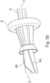
- Figure 5a illustrates the attachment of an advantageous embodiment of the contamination protection device according to the invention to the proximal end of the endoscope shaft 1. Shown are the proximal clamping bracket 93 on the seal 92 and the air and water hoses 4a, 4b, for which corresponding recesses are provided on the clamping bracket 93.
- the fabric hose 32 is shown at the top edge of the picture, which firmly encloses the endoscope shaft 1 together with the air and water hoses 4a, 4b running thereon and forms a base for the inner sleeve 3 to be unrolled.
- Figure 5c shows the form-fitting fixation of the inner and outer casing 3, 6 with the aid of the clamp 91, which presses the two casings onto the proximal clamping bracket 93 located underneath.
- the free ends of the inner and outer shell 3, 6 protruding beyond the clamp 91 are additionally held together by the clamp 94 and, for example, protected against unintentional tearing.
- the outer sleeve 6 is unrolled over the distal end of the shaft.
- proximal clamp 93 nor the distal clamp 96 have to be removed between two contamination-protected examinations. This means that the time required to prepare the endoscope for a further examination is advantageously shortened by the fact that after the contamination protection has been dismantled, the clamping brackets including the seals located underneath remain on the shaft and can be used to attach a further contamination protection.
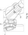
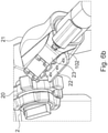
- the Figures 6a to 6c show partial steps of the attachment of an embodiment of the grip attachment 21 according to the invention. This is typically made in at least two parts, one part being an in Figure 6a illustrated ergonomically shaped handpiece 21, which is attached to the side of the handle 2 of the endoscope.
- valve holder 22 is characterized by receptacles for three valves
- instrument holder 23 forms a receptacle for the two-way hose distributor 24, which is arranged above the proximal instrument channel opening 102.
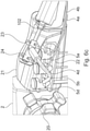
- Figure 6c shows the final assembly state.
- the three valves for air, water and suction 5a, 5b, 5c are inserted into the corresponding receptacles on the valve holder 22 and connected to the air and water hoses 4a, 4b coming from the distal end of the endoscope shaft 1 and the suction hose 4d.
- the hoses exiting the valves are connected to appropriate devices, by means of which the channels can be pressurized with overpressure, underpressure or water.
- the treating doctor can open the three valves 5a, 5b, 5d with the touch of a finger.
- these valves are inexpensive single-use products that are disposed of and changed after each examination.
- the y-shaped two-way tubing manifold 24 shown in the instrument holder 23 is inserted and is connected to the working tube 4c protruding from the proximal instrument channel opening 102.
- the suction hose 4d is connected to the laterally exiting distributor legs, the straight leg of the distributor serves as access for instruments 80 to be used in the course of the examination.
- the area between the distal end of the two-way hose distributor 24 and the proximal instrument channel opening 102, in which the working tube 4c is exposed, is provided for cutting through the working tube 4c in the course of disassembly after the endoscopy has taken place. Curling tongs should advantageously be used for the cutting, which fuses the two cut ends immediately in a germ-proof manner in order to prevent the contamination present in the working hose 4c from escaping.
- FIG. 7 shows an embodiment of the contamination protection device that is preassembled during production for quick and user-friendly attachment to the endoscope shaft 1.
- the aim here is to pull the device onto the shaft 1 in one piece.
- the inner casing 3 and outer casing 6 lie on top of each other and are rolled up together up to the cap 31.
- the air and water hoses 4a, 4b that open out into the front side of the cap 31 are wound up in a spiral, with the winding having a larger diameter than the shaft 1.
- Both hoses 4a, 4b are fixed to the clamp 94 and connected with their proximal ends to the air valve 5a and the water valve 5b.
- the proximal end of the working tube 4c which also ends distally in the end face of the cap 31, is inserted into the distal instrument channel opening 101 and the entire aforementioned structure is pushed over the shaft tip onto the shaft 1 until the cap 31 is on the previously mounted distal clamping bracket 96 snaps into place.
- the clamp 94 is pushed up over the proximal clamping bracket 93, which was likewise installed beforehand, and the inner sleeve 3 and outer sleeve 6 are unrolled in the process. Then only the proximal ends of the two sleeves 3, 6 have to be pushed into the clamp 94 and the clamp 91 closed around it for fixing and sealing in the area of the proximal clamping bracket 93.
- air valve 5a and water valve 5b are attached to the handle attachment 21 and the working hose protruding from the proximal instrument channel opening 102 can be connected to the two-way hose distributor 24 .
- a bracket-like clamp 33 is formed on the proximal end of the cap 31 .
- This is made of a suitably deformable plastic and can be bent around the endoscope shaft and fixed via the click fastener 331, 331'.
- Air hose opening 30a and water hose opening 30b are arranged in a tube shape in a web 332, which clamp 31 and clamp 33 connects.
- the advantage of this embodiment is its smaller diameter compared to the variant with a distal clamping bracket.
- the cap 31 shown with the clamp 33 can advantageously also be used accordingly in an embodiment of the contamination protection device that is preassembled on the production side Figure 7 find use.
- the distal end of the cap can also be made from an optically neutral shrink tubing.
- the objects described in claims 2 to 4 are shown, which serve to connect the distal end of the outer sleeve 6 to the patient.
- this is the diaper pants 7a according to the invention, which are used in colonoscopies.
- These diaper pants 7a are put on by the patient to be examined and have an opening with a connection part 71a, which is suitably positioned relative to the body opening to be examined, ie anus or enterostoma.
- the outer casing 6 can be connected to this connecting part 71a by means of the connecting piece 61a provided at its distal end in an advantageous embodiment, so that an airtight, watertight and germ-tight connection is created.
- the endoscope shaft 1 protected by the inner sleeve 3 is then pushed through the opening provided in the diaper pants 7a and inserted into the body opening of the patient to be examined.
- the intestinal contents or other body fluids that emerge during the examination are thus drained through the diaper pants 7a on the one hand and the on the other hand, the protective volume formed between the outer and inner shell 6, 3 is prevented from escaping into the examination environment.
- the teething ring 7b is used for gastroscopies, at the opening of which the connection part 71b is held up. This in turn serves to connect the outer shell 6 to the patient via the connecting piece 61b.
- the teething ring 7b can be expanded to include sections that enclose the face or at least the jaw area of the patient like a mask.
- a partition wall 7c with an opening and connection part 71c can be used, behind which the patient is positioned during the endoscopic examination.
- the attending physician acts from the front of the partition and is thus protected from direct contamination.
- the dividing wall 7c can take the form of a closed cabin, except for the lead-through opening, in which all contaminations conveyed out of the patient during the examination remain enclosed.
- FIG. 10 shows an embodiment of the endoscope according to the invention, in which a stretched film 7c is used as a separation between the patient and the attending physician.
- This film is provided with an opening to which the outer shell 6 is welded with its distal end, as a result of which an airtight, watertight and germ-tight connection is realized here.
- the separating film 7c should be dimensioned in such a way that it can be folded over and placed under the patient to be examined. As a result, all dirt that occurs during the examination is collected on the film and kept away from the rest of the examination environment, in particular the patient couch.
- FIG. 11 shows the instrument protection 8 according to the invention together with a performed instrument 80, which usually consists of a Micro device 80a consists of an instrument Bowden cable 80b and can be operated with the control element 80c.
- the instrument protection 8 consists of an instrument hose 81 pushed on here like a bellows, which is delimited at both ends by the instrument hose caps 82, on the end faces of which openings for the passage of the instrument 80 are provided.
- the instrument protection 8 is connected to the proximal end of the straight leg of the two-way hose distributor 24 in the illustrated folded state like a bellows.
- the instrument 80 In order to remove the soiled parts of the instrument 80 from the working hose 4c after the surgical intervention without releasing any contamination, it is drawn into the instrument hose 81, which is pulled out to its full length for this purpose.
- the length of the instrument hose 81 is accordingly to be dimensioned in such a way that the micro-device 80a together with the Bowden cable 80b can be completely encased by it.
- the instrument 80 After the instrument 80 has been pulled into the instrument protection 8, it can be removed from the two-way hose distributor 24, with all dirt being held back inside the instrument hose 81.
- Figures 12a to 12c show an advantageous embodiment of the working hose 4c according to the invention with a protective hose 4c1, which is conducive to contamination-protected disassembly.
- the working hose 4c has a predetermined breaking point 4c0, for example in the form of a circumferential notch.
- the protective hose 4c1 is connected to the outside of the working hose 4c in an airtight, watertight and germ-tight manner over the entire circumference, typically by a welded or adhesive connection.
- Figure 12b is shown how the protective hose after breaking the predetermined breaking point 4c0 by pulling on the two separate ends of the Working hose 4c is drawn in length, whereby it is finally torn.
- the polymeric material used for the protective hose 4c1 should have a significantly higher elongation at break than the material of the working hose 4c, so that the end sections torn apart as in Figure 12c are shown so strongly plastically deformed that they close the ends of the working hose 4c like a pocket and protect against the escape of contamination.
- figure 13 shows a perspective overall view of a further embodiment of the endoscope according to the invention with a contamination protection device, in which the two-way hose distributor is connected directly to the proximal instrument channel opening.
- the tubing manifold 24' connects directly to the proximal instrument channel opening 102.
- the air and water valves are combined in a single valve 5ab, which is used together with the suction valve 5d in holders provided for this purpose in the handle 2.
- the proximal end of the working hose 4c leading out of the proximal instrument channel opening 102 and the suction hose 4d leading to the suction valve 5d are connected to the two-way hose distributor 24'.
- the hoses for the compressed air 4a and the water supply 4b are wound around the shaft 1 to secure them and are routed to the combined air/water valve 5ab and connected there.
- figure 14 is the two-way hose distributor of the embodiment suitable for direct connection to the instrument channel opening figure 13 shown schematically in detail.
- the y-shaped two-way hose distributor 24' has three ends or connections.
- the distal end 241 which can in particular have a conical shape, can be inserted into the proximal end 242 of the working hose 4c led out of the instrumentation channel opening 102 .
- the suction tube 4d is connected to one of the two proximal ends, the other end 242 is open and serves as an instrument access.
- the hose distributor 24' is equipped with a ring nut 243, which is seated on the hose distributor 24' in an axially displaceable manner.
- a radially protruding collar 244 formed in the area of the distal end 241 interacts with a stop of the ring nut 243 in order to fasten the tube distributor to a corresponding connection means of the proximal instrument channel opening 102 after the ring nut has been fixed.
- the instrumentation channel opening 102 can have, for example, a widely used Luer lock connection.
- Figures 15A - D illustrate the procedure for the direct connection of a hose distributor suitable for this purpose of the embodiment according to FIG Figures 13 and 14 .
- the working hose 4c is pushed sufficiently far out of the proximal instrument channel opening 102. Then the two-way hose distributor 24' is connected with its distal end 41 by plugging it into the working hose, part figure B.
- the working hose 4c is designed here in such a way that the pressure forces exerted when the two-way hose distributor 24' is inserted the proximal end of the working hose is compressed like a bellows and the bellows section 4c' is thus formed.
- Subfigure C shows the step in which the ring nut 243 of the hose distributor 24' is connected to the proximal instrument channel opening with the aid of a connection means, here a Luer lock connection.
- the endoscope is ready for an examination or operation.
- the two-way hose distributor 24' is detached again and together with the working channel from the proximal instrument channel openings 102 is pulled away, as a result of which the bellows section 4c' of the working channel 4c unfolds again.
- the working hose can now be severed and sealed in one step with hot scissors and thus pulled distally out of the instrumentation channel without contamination.
- figure 16 shows a further embodiment of an endoscope according to the invention with two instrumentation channels and correspondingly two working hoses.
- the distal end of the shaft 1 shown in the left part of the figure has two distal instrument channel openings 101 into which a working hose 4c is to be pushed as part of the protection against contamination according to the invention.
- the two instrumentation channels of the endoscope shown here open proximally into two corresponding instrumentation channel openings 102, partial figure at the top right.
- the valve holders with valves 5ab for air and water and 5d for suction are also shown in this partial figure.
- the instrument channel openings 102 are shown closed with protective caps in the partial figure at the bottom right.
Landscapes
- Health & Medical Sciences (AREA)
- Life Sciences & Earth Sciences (AREA)
- Surgery (AREA)
- Nuclear Medicine, Radiotherapy & Molecular Imaging (AREA)
- Biomedical Technology (AREA)
- Optics & Photonics (AREA)
- Pathology (AREA)
- Radiology & Medical Imaging (AREA)
- Biophysics (AREA)
- Engineering & Computer Science (AREA)
- Physics & Mathematics (AREA)
- Heart & Thoracic Surgery (AREA)
- Medical Informatics (AREA)
- Molecular Biology (AREA)
- Animal Behavior & Ethology (AREA)
- General Health & Medical Sciences (AREA)
- Public Health (AREA)
- Veterinary Medicine (AREA)
- Endoscopes (AREA)
Claims (19)
- Endoscope avec dispositif de protection contre la contamination comportant- une manche rigide ou flexible (1), au bout de laquelle sont disposés une optique (11), un dispositif d'éclairage (12) et une tuyère (13),- une poignée (2) fixée à la manche (1),- un gaine intérieur (3) qui est fermé à l'une de ses extrémités distales et qui est optiquement transparent au moins sur la face avant et qui est enroulé le long de la manche (1) à la manière d'un préservatif,- dans chaque cas au moins un tuyau d'air (4a) et un tuyau d'eau (4b), qui se terminent ouvertement à l'extrémité distale du gaine intérieur (3) et y sont reliés et qui sont placés entre l'arbre (1) et le gaine intérieure (3), etdans lequel une gaine externe (6) envellope la gaine interne (3) et est reliée à celle-ci à une extrémité proximale de la gaine interne (3) d'une manière étanche à l'air, à l'eau et aux germes.
- Endoscope selon la revendication 1, caractérisé en ce qu' à une extrémité distale de la gaine extérieure (6)- un premier pièce de connexion (61a) est formé, et une paire de couches (7a) pour un patient à examiner par coloscopie est fournie, qui a une ouverture avec une première partie de réception (71a) à laquelle le premier connecteur (61a) de la gaine extérieure (6), est reliée de manière étanche à l'air, à l'eau et aux germes, et/ou- une deuxième pièce de connexion (61b) est formée, et un anneau de dentition (7b) pour un patient à examiner par gastroscopie est prévu, qui présente une ouverture avec une deuxième partie de réception (71b) à laquelle la deuxième pièce de connexion (61b) de la gaine extérieure (6) est reliée de manière étanche à l'air, à l'eau et aux germes, et/ou- une troisième pièce de connexion (61c) est formé, et il est prévu une cloison (7c) ou cabine pour un patient à examiner à positionner derrière ou dans elle, qui présente une ouverture avec une troisième partie de réception (71c) à laquelle la troisième pièce de connexion de la gaine extérieure (6) est connectée de manière étanche à l'air, à l'eau et aux germes.
- Endoscope selon la revendication 1, caractérisé en ce qu'un film avec une ouverture est soudé à une extrémité distale de la gaine extérieure (6) de manière étanche à l'air, à l'eau et aux germes et est étiré devant un patient à examiner au moyen d'un dispositif de maintien.
- Endoscope selon l'une des revendications précédentes, caractérisé en ce que la gaine intérieure (3) et la gaine extérieure (6)- se composent d'un matériau étanche à l'air et à l'eau qui est imperméable aux germes, et/ou- se composent d'un matériau flexible et compressible, c'est-à-dire qu'il peut notamment être enroulé ou plié comme un soufflet.
- Endoscope selon l'une des revendications 1 à 4, caractérisé en ce que- Au moins un canal d'instrument (10) s'étend dans la manche (1), qui s'ouvre dans une ouverture de canal d'instrument distal (101) sur la pointe de la manche et dans une ouverture de canal d'instrument proximal (102) sur la poignée (2),- le gaine intérieur (3) présente une ouverture de tuyau de travail (30c) qui est congruente à l'ouverture de canal d'instrument distal (101) sur la face avant, et- un tuyau de travail (4c) est formé sur l'ouverture de tuyau de travail (30c) de manière étanche aux germes, qui est positionné dans le canal d'instrumentation (10) et dépasse de l'ouverture de canal d'instrumentation proximale (102).
- Endoscope selon la revendication 5, caractérisé en ce que le tuyau de travail (4c) présente un point de rupture prédéterminé (4c0) dans sa section dépassant de l'ouverture proximale du canal instrumental (102), et qu'un tuyau de protection (4c1) en matériau polymère, qui a un allongement à la rupture plus élevé qu'un matériau du tuyau de travail (4c) est fixé à l'extérieur ou à l'intérieur du tuyau de travail (4c) de telle sorte que le tuyau de protection (4c1) est connecté avec le tuyau de travail (4c1) d'une manière étanche à l'air, à l'eau et aux germes à la fois devant et derrière le point de rupture prédéterminé (4c0).
- Endoscope selon l'une des revendications 1 à 6, caractérisé par- une porte-valve (22a, 22b) dans la poignée (2), dans lesquels une valve à air (5a) et une valve à eau (5b) ou une valve combinée air/eau (5ab) intégrée dans un bloc de valve (5ab) et un la valve (5d) peut être insérée, et- un distributeur de tuyau bidirectionnel (24') avec une extrémité distale, en particulier de forme conique, (241) insérée dans une extrémité proximale du tuyau de travail (4c), le distributeur de tuyau (24') ayant en outre en particulier une ouverture pour instrument (242) et possède un écrou annulaire (243) qui est déplaçable axialement par rapport au tuyau de travail (4c) et au moyen duquel il peut être fixé à une ouverture de canal d'instrument proximal (102) de l'endoscope.
- Endoscope selon l'une des revendications 1 à 6, caractérisé par un embout de poignée (21) qui est fixé sur la poignée (2) et dans lequel :- une vanne d'air (5a) et une vanne d'eau (5b) dans un porte-vanne (22),- un support d'instrument (23) avec un distributeur de tuyau à 2 voies (24) inséré à l'intérieur, à une extrémité distale auquel le tuyau de travail (4c) est connecté,- une soupape d'aspiration (5d), et- un tuyau d'aspiration (4d) qui est connecté à une première extrémité proximale du distributeur de tuyau (24) et à la soupape d'aspiration (5d).
- Endoscope selon la revendication 8, caractérisé en ce qu' une protection d'instrument (8) est reliée à une seconde extrémité proximale du distributeur de tuyau (24), qui se compose d'un tuyau d'instrument en forme de soufflet (81) qui a un capuchon de protection d'instrument (82 ) à chaque extrémité avec une ouverture à l'avant et a une longueur qui est supérieure à une longueur du tuyau de travail (4c).
- Endoscope selon l'une des revendications précédentes, caractérisé en ce que la gaine interne (3) et/ou la gaine externe (6) est fixée à une extrémité proximale de la manche (1) sur une surface latérale de la manche (1), en particulier en ce qu'il est fixé par une pince (91) ou un anneau en caoutchouc pouvant être pressé sur un support de serrage proximal (93) qui est disposé sur la surface latérale de la manche (1) et est recouvert d'un joint proximal (92 ) et qui a des ouvertures pour le tuyau d'air (4a) et le tuyau d'eau (4b).
- Endoscope selon l'une des revendications précédentes, caractérisé en ce que l'extrémité distale de la gaine intérieure (3) est conçue comme un capuchon cylindrique sensiblement creux (31) avec une face d'extrémité ouverte, qui présente une ouverture de tuyau d'air (30a) et un ouverture de tuyau d'air (30a) sur une face d'extrémité opposée à la face d'extrémité ouverte Possède une ouverture de tuyau d'eau (30b) sur laquelle sont formés le tuyau d'air (4a) et le tuyau d'eau (4b), dans lequel- une bride en forme d'équerre (33) avec une fermeture à encliquetage (331, 331') est surmoulée sur le capuchon (31) et le capuchon (31) est fixé à l'extrémité distale de la manche (1) par le fait qu'il est fixé à un La surface circonférentielle de l'arbre (1) et recouverte d'un joint distal (95) repose sur le support de serrage distal (96) qui comporte des ouvertures pour le tuyau d'air (4a) et le tuyau d'eau (4b), ou- sur une face d'extrémité ouverte du capuchon (31) pour le serrage sur l'extrémité distale de l'arbre, des branches élastiques s'étendant axialement sont formées.
- Endoscope selon l'une des revendications précédentes, caractérisé en ce que la gaine intérieure (3) et la gaine extérieure (6) sont réalisées d'un seul tenant, c'est-à-dire la liaison étanche à l'air, à l'eau et aux germes de la gaine extérieure (6) avec l'extrémité proximale de la gaine intérieure (3) est déjà maintenue du côté de la production, par exemple par soudage, et/ou la gaine intérieure (3) est recouverte d'un tube en tissu et/ou la gaine extérieure (6) gaine la poignée (2) et la fixation de poignée (21).
- Endoscope selon les revendications 8 et 12, caractérisé en ce que le distributeur de tuyaux à deux voies (24) est intégré dans la section de l'gaine extérieure (6) qui entoure la pièce de poignée (2) et la fixation de poignée (21).
- Procédé de fixation d'un dispositif de protection contre la contamination pour un endoscope selon la revendication 1, caractérisé par les étapes :- Exposition de la zone optiquement transparente à l'extrémité distale de la gaine intérieure (3) avec une substance qui établit un contact optique avec l'optique (11) de l'endoscope,- Fixez la fixation de poignée (21) à la poignée (2),- Insertion de l'extrémité distale de la manche d'endoscope (1) dans la gaine intérieure enroulée (3),- déroulement en forme de préservatif de la gaine intérieure (3) comprenant la manche (1) et le tuyau d'air (4a) et le tuyau d'eau (4b) positionnés dessus,- Connectez les extrémités proximales du tuyau d'air (4a) et du tuyau d'eau (4b) à la vanne d'air (5a) et à la vanne d'eau (5b) sur la fixation de la poignée (21),- Glisser la couverture extérieure enroulée (6) sur la couverture intérieure (3) et la fixer à l'extrémité proximale de la couverture intérieure (3) et qui est imperméable à l'air, à l'eau et aux germes, et- déroulement semblable à un préservatif de l'gaine extérieure (6) au-delà de l'extrémité de la manche de l'endoscope (1).
- Procédé de fixation d'un dispositif de protection contre la contamination pour un endoscope selon la revendication 2 selon les étapes de procédé selon la revendication 14, caractérisé en ce qu'alors le premier ou le deuxième ou le troisième connecteur (61a, b, c) de la gaine externe (6) avec le premier, le deuxième ou le troisième connecteur (71a, b, c) est connecté.
- Procédé de fixation d'un dispositif de protection contre la contamination pour un endoscope selon la revendication 11 selon les étapes de procédé selon l'une des revendications 14 ou 15, caractérisé en ce que les étapes suivantes sont exécutées pour fixer et relier la gaine interne (3) et la gaine externe (6) :- Collage du joint proximal (92) sur la surface latérale de l'extrémité proximale de la manche (1),- Fixation de la pince proximale (93) au joint proximal (92),- Collage du joint distal (95) sur la surface latérale de l'extrémité distale de la manche (1),- Fixation de la pince distale (96) au joint distal (95) à l'aide d'une aide au positionnement (960),- Positionner le tuyau d'air (4a) et le tuyau d'eau (4b) dans les passages du support de serrage distal (96),- Placer le capuchon (31) sur l'étrier de serrage distal (96),- Positionner le tuyau d'air (4a) et le tuyau d'eau (4b) dans les passages du support de serrage proximal (93),- Positionner les extrémités proximales de la gaine intérieure (3) et de la gaine extérieure (6) sur le support de serrage proximal (93), et- Serrage de la gaine intérieure (3) et de la gaine extérieure (6) entre l'étrier de serrage proximal (93) et la pince (91) ou la bague en caoutchouc
- Procédé de fixation d'un dispositif de protection contre la contamination pour un endoscope selon la revendication 11 selon les étapes de procédé selon l'une des revendications 14 à 16, caractérisé en ce qu'avant l'introduction de l'extrémité distale de la manche (1) dans l'intérieur de la gaine (3) enroulé, l'extrémité proximale du tuyau de travail (4c) est insérée si loin dans l'ouverture distale du canal d'instrument (101) qu'elle dépasse de l'ouverture proximale d'instrument (102), puis- l'extrémité proximale du tuyau de travail (4c) est connecté avec l'extrémité distale d'un distributeur de tuyau à 2 voies (24, 24'),- la première extrémité proximale du tuyau distributeur (24, 24') est connecté avec la soupape d'aspiration (5d) au moyen du tuyau d'aspiration (4d), et- la deuxième extrémité proximale du tuyau distributeur (24, 24') est connecté avec la protection d'instrument froncée en forme de soufflet (8).
- Procédé selon la revendication 17, caractérisé en ce que le tuyau distributeur (24') est fixé directement sur l'ouverture proximale du canal d'instruments (102) au moyen d'un écrou annulaire (243).
- Procédé de préparation d'un endoscope selon l'une des revendications 1 à 13 pour un deuxième examen endoscopique protégé contre la contamination après la mise en œuvre protégée contre la contamination d'un premier examen endoscopique, dont la dernière étape consiste à retirer la manche de l'endoscope de l'ouverture corporelle examinée ,
caractérisé par les étapes :- Découper la gaine extérieure (6) au niveau de son extrémité distale et le tuyau d'air (4a) et le tuyau d'eau (4b) au niveau du manche (2) chacun avec un fer à friser, et- Démontage et élimination du dispositif de protection contre la contamination, avec étriers de serrage (93, 96) fixés sur la surface extérieure de la manche pouvant être laissés sur l'endoscope,- Fourniture d'une protection supplémentaire contre la contamination comprenant une gaine intérieure (3), une gaine extérieure (6) ainsi que des tuyaux d'eau, d'air et de travail (4a, 4b, 4c), et- Assemblage de la protection supplémentaire contre la contamination selon l'une des revendications 14 à 18, la fixation de l'étrier de serrage proximal (93) et de l'étrier de serrage distal (96) étant éventuellement omis car redondant.
Applications Claiming Priority (2)
| Application Number | Priority Date | Filing Date | Title |
|---|---|---|---|
| DE102018110228.3A DE102018110228A1 (de) | 2018-04-27 | 2018-04-27 | Vorrichtung und Verfahren zur kontaminationsfreien Durchführung einer endoskopischen Untersuchung |
| PCT/DE2019/100380 WO2019206381A1 (fr) | 2018-04-27 | 2019-04-26 | Dispositif et procédé de réalisation d'un examen endoscopique sans contamination |
Publications (2)
| Publication Number | Publication Date |
|---|---|
| EP3723576A1 EP3723576A1 (fr) | 2020-10-21 |
| EP3723576B1 true EP3723576B1 (fr) | 2022-02-23 |
Family
ID=66776063
Family Applications (1)
| Application Number | Title | Priority Date | Filing Date |
|---|---|---|---|
| EP19728861.6A Active EP3723576B1 (fr) | 2018-04-27 | 2019-04-26 | Dispositif et procédé de réalisation d'un examen endoscopique sans contamination |
Country Status (7)
| Country | Link |
|---|---|
| US (1) | US12329357B2 (fr) |
| EP (1) | EP3723576B1 (fr) |
| JP (1) | JP2021520929A (fr) |
| DE (2) | DE102018110228A1 (fr) |
| DK (1) | DK3723576T3 (fr) |
| ES (1) | ES2913098T3 (fr) |
| WO (1) | WO2019206381A1 (fr) |
Families Citing this family (12)
| Publication number | Priority date | Publication date | Assignee | Title |
|---|---|---|---|---|
| GB2577912A (en) * | 2018-10-10 | 2020-04-15 | Surgease Innovations Ltd | Digital endoscope |
| DE102019105438A1 (de) | 2019-03-04 | 2020-09-10 | Jürgen Kress | Endoskop mit Schnellwechselschläuchen |
| US12575721B2 (en) | 2019-05-01 | 2026-03-17 | Ambu A/S | Devices, systems, and methods for treating kidney stones |
| CN111358417B (zh) * | 2020-03-05 | 2022-02-22 | 上海市肺科医院(上海市职业病防治院) | 智能化一体式气管镜防护预清洁装置 |
| CN112603244B (zh) * | 2020-12-09 | 2024-08-13 | 佛山阿克索医疗科技有限公司 | 一种内镜手术用辅助探头及其使用方法 |
| TWI790646B (zh) * | 2021-06-15 | 2023-01-21 | 施長碧 | 用於內視鏡之拋棄式外膜套機構 |
| CN217310362U (zh) * | 2022-04-21 | 2022-08-30 | 南微医学科技股份有限公司 | 内衬套及超声内镜 |
| US12582293B2 (en) * | 2022-06-24 | 2026-03-24 | Olympus Medical Systems Corp. | Insertion instrument and endoscope system |
| CN116250792B (zh) * | 2023-02-28 | 2025-07-25 | 湖南省华芯医疗器械有限公司 | 一种前端组件、插入部及内窥镜 |
| EP4701503A1 (fr) * | 2023-05-15 | 2026-03-04 | Boston Scientific Scimed, Inc. | Valve d'aspiration avec tige sollicitée vers l'extérieur pour un endoscope |
| CN117562485B (zh) * | 2023-11-27 | 2024-06-14 | 济南显微智能科技有限公司 | 一种可调节的蛇骨型3d内窥镜 |
| CN118177687B (zh) * | 2024-03-15 | 2024-09-17 | 济南显微智能科技有限公司 | 一种可调型的3d内窥镜 |
Family Cites Families (13)
| Publication number | Priority date | Publication date | Assignee | Title |
|---|---|---|---|---|
| US3866601A (en) * | 1973-02-20 | 1975-02-18 | James A Russell | Telescopic speculum |
| US4593699A (en) * | 1983-06-13 | 1986-06-10 | Poncy Richard P | Sterile cover for intraoperative ultrasonic diagnostic devices and method and kit for providing same |
| US4646722A (en) * | 1984-12-10 | 1987-03-03 | Opielab, Inc. | Protective endoscope sheath and method of installing same |
| US4907395A (en) * | 1988-05-13 | 1990-03-13 | Opielab, Inc. | Packaging system for disposable endoscope sheaths |
| US5388593A (en) * | 1991-11-04 | 1995-02-14 | Marshfield Medical Research & Education Foundation | Surgical drape for endoscopy |
| US5217001A (en) * | 1991-12-09 | 1993-06-08 | Nakao Naomi L | Endoscope sheath and related method |
| US5433221A (en) * | 1994-10-05 | 1995-07-18 | Adair; Edwin L. | Windowed self-centering drape for surgical camera |
| US6357445B1 (en) * | 2000-09-11 | 2002-03-19 | Timothy A. Shaw | Surgical drape for colonoscopy |
| ATE338507T1 (de) | 2003-01-03 | 2006-09-15 | Juergen Kress | Hygieneschutz für endoskope |
| ATE526863T1 (de) * | 2005-08-17 | 2011-10-15 | Kress Juergen | Hygieneschutz für endoskope und endoskop mit hygieneschutz |
| WO2009086396A1 (fr) | 2007-12-27 | 2009-07-09 | Wilson-Cook Medical Inc. | Gaine d'endoscope de distributeur à bande multiple |
| JP2012523855A (ja) * | 2009-03-25 | 2012-10-11 | ザ クリーブランド クリニック ファウンデーション | 医用器具シース |
| CN102038479B (zh) * | 2009-10-23 | 2012-05-23 | 姜克让 | 内窥镜一次性防护套 |
-
2018
- 2018-04-27 DE DE102018110228.3A patent/DE102018110228A1/de not_active Withdrawn
-
2019
- 2019-04-26 DK DK19728861.6T patent/DK3723576T3/da active
- 2019-04-26 DE DE112019002179.6T patent/DE112019002179A5/de active Pending
- 2019-04-26 US US16/965,978 patent/US12329357B2/en active Active
- 2019-04-26 JP JP2020556259A patent/JP2021520929A/ja active Pending
- 2019-04-26 WO PCT/DE2019/100380 patent/WO2019206381A1/fr not_active Ceased
- 2019-04-26 EP EP19728861.6A patent/EP3723576B1/fr active Active
- 2019-04-26 ES ES19728861T patent/ES2913098T3/es active Active
Also Published As
| Publication number | Publication date |
|---|---|
| US20210030261A1 (en) | 2021-02-04 |
| JP2021520929A (ja) | 2021-08-26 |
| DE102018110228A1 (de) | 2019-10-31 |
| ES2913098T3 (es) | 2022-05-31 |
| DE112019002179A5 (de) | 2021-02-25 |
| WO2019206381A1 (fr) | 2019-10-31 |
| DK3723576T3 (da) | 2022-04-11 |
| US12329357B2 (en) | 2025-06-17 |
| EP3723576A1 (fr) | 2020-10-21 |
Similar Documents
| Publication | Publication Date | Title |
|---|---|---|
| EP3723576B1 (fr) | Dispositif et procédé de réalisation d'un examen endoscopique sans contamination | |
| DE68915330T2 (de) | Verpackungseinheit für Endoskophüllen zum einmaligen Gebrauch. | |
| US6908428B2 (en) | Sleeve for endoscopic tools | |
| US5217001A (en) | Endoscope sheath and related method | |
| EP1284120B1 (fr) | Gaine à usage unique pour un endoscope | |
| DE69218942T2 (de) | Schutzhülle für endoskop zur verhütung von ansteckung | |
| EP1915087B1 (fr) | Protection hygienique destinee a des endoscopes et endoscope comportant une protection hygienique | |
| DE4229873C1 (de) | Endoskopischer Prüfverschluß | |
| US20050085694A1 (en) | Endoscope with open channels | |
| EP1083821A1 (fr) | Gaine protectrice utilisee lors de la sterilisation d'endoscopes souples | |
| DE19815598A1 (de) | Flexibler Trokar mit Stülpschlauchsystem | |
| EP1578255A1 (fr) | Element de protection hygienique pour endoscope | |
| DE102019105438A1 (de) | Endoskop mit Schnellwechselschläuchen | |
| JP2009515639A (ja) | 内視鏡器具の保護スリーブ | |
| EP1034010A2 (fr) | Dispositif d'aide a l'insertion endoscopique | |
| EP2982327B1 (fr) | Enveloppe sterile pour un instrument d'observation medicale et procede de fonctionnement d'un instrument d'observation medicale | |
| EP3148396B1 (fr) | Conditionnement pour endoscope muni de deux compartiments séparés | |
| US20150094611A1 (en) | Method and Device for Improved Hygiene During using Endoscopic accessory tools | |
| EP1997452B1 (fr) | Dispositif d'enveloppement stérile d'un élément de commande sensible à la stérilisation | |
| DE202014000037U1 (de) | Endoskopievorrichtung | |
| EP2903494A1 (fr) | Système d'endoscopie et de biopsie à usage unique | |
| EP1262146A2 (fr) | Appareil médical en forme de tunnel et son élément protecteur | |
| DE20316892U1 (de) | Schutzvorrichtung gegen Kontamination in der medizinischen Endoskopie | |
| DE102021103087A1 (de) | Absaugventil und Luft-/Wasserventil für Hohlraumkörperinstrumente mit einem Brückenelement zur Spülung des Absaugkanals | |
| DE102023117768A1 (de) | Längliche endoskopische abdeckung |
Legal Events
| Date | Code | Title | Description |
|---|---|---|---|
| STAA | Information on the status of an ep patent application or granted ep patent |
Free format text: STATUS: UNKNOWN |
|
| STAA | Information on the status of an ep patent application or granted ep patent |
Free format text: STATUS: THE INTERNATIONAL PUBLICATION HAS BEEN MADE |
|
| PUAI | Public reference made under article 153(3) epc to a published international application that has entered the european phase |
Free format text: ORIGINAL CODE: 0009012 |
|
| STAA | Information on the status of an ep patent application or granted ep patent |
Free format text: STATUS: REQUEST FOR EXAMINATION WAS MADE |
|
| 17P | Request for examination filed |
Effective date: 20200714 |
|
| AK | Designated contracting states |
Kind code of ref document: A1 Designated state(s): AL AT BE BG CH CY CZ DE DK EE ES FI FR GB GR HR HU IE IS IT LI LT LU LV MC MK MT NL NO PL PT RO RS SE SI SK SM TR |
|
| AX | Request for extension of the european patent |
Extension state: BA ME |
|
| STAA | Information on the status of an ep patent application or granted ep patent |
Free format text: STATUS: EXAMINATION IS IN PROGRESS |
|
| DAV | Request for validation of the european patent (deleted) | ||
| DAX | Request for extension of the european patent (deleted) | ||
| 17Q | First examination report despatched |
Effective date: 20210714 |
|
| GRAP | Despatch of communication of intention to grant a patent |
Free format text: ORIGINAL CODE: EPIDOSNIGR1 |
|
| STAA | Information on the status of an ep patent application or granted ep patent |
Free format text: STATUS: GRANT OF PATENT IS INTENDED |
|
| INTG | Intention to grant announced |
Effective date: 20211116 |
|
| GRAS | Grant fee paid |
Free format text: ORIGINAL CODE: EPIDOSNIGR3 |
|
| GRAA | (expected) grant |
Free format text: ORIGINAL CODE: 0009210 |
|
| STAA | Information on the status of an ep patent application or granted ep patent |
Free format text: STATUS: THE PATENT HAS BEEN GRANTED |
|
| AK | Designated contracting states |
Kind code of ref document: B1 Designated state(s): AL AT BE BG CH CY CZ DE DK EE ES FI FR GB GR HR HU IE IS IT LI LT LU LV MC MK MT NL NO PL PT RO RS SE SI SK SM TR |
|
| REG | Reference to a national code |
Ref country code: GB Ref legal event code: FG4D Free format text: NOT ENGLISH |
|
| REG | Reference to a national code |
Ref country code: CH Ref legal event code: EP |
|
| REG | Reference to a national code |
Ref country code: DE Ref legal event code: R096 Ref document number: 502019003505 Country of ref document: DE |
|
| REG | Reference to a national code |
Ref country code: AT Ref legal event code: REF Ref document number: 1469800 Country of ref document: AT Kind code of ref document: T Effective date: 20220315 |
|
| REG | Reference to a national code |
Ref country code: IE Ref legal event code: FG4D Free format text: LANGUAGE OF EP DOCUMENT: GERMAN |
|
| REG | Reference to a national code |
Ref country code: DK Ref legal event code: T3 Effective date: 20220406 |
|
| REG | Reference to a national code |
Ref country code: NL Ref legal event code: FP |
|
| REG | Reference to a national code |
Ref country code: SE Ref legal event code: TRGR |
|
| REG | Reference to a national code |
Ref country code: ES Ref legal event code: FG2A Ref document number: 2913098 Country of ref document: ES Kind code of ref document: T3 Effective date: 20220531 |
|
| REG | Reference to a national code |
Ref country code: LT Ref legal event code: MG9D |
|
| PGFP | Annual fee paid to national office [announced via postgrant information from national office to epo] |
Ref country code: NL Payment date: 20220419 Year of fee payment: 4 |
|
| PG25 | Lapsed in a contracting state [announced via postgrant information from national office to epo] |
Ref country code: RS Free format text: LAPSE BECAUSE OF FAILURE TO SUBMIT A TRANSLATION OF THE DESCRIPTION OR TO PAY THE FEE WITHIN THE PRESCRIBED TIME-LIMIT Effective date: 20220223 Ref country code: PT Free format text: LAPSE BECAUSE OF FAILURE TO SUBMIT A TRANSLATION OF THE DESCRIPTION OR TO PAY THE FEE WITHIN THE PRESCRIBED TIME-LIMIT Effective date: 20220623 Ref country code: NO Free format text: LAPSE BECAUSE OF FAILURE TO SUBMIT A TRANSLATION OF THE DESCRIPTION OR TO PAY THE FEE WITHIN THE PRESCRIBED TIME-LIMIT Effective date: 20220523 Ref country code: LT Free format text: LAPSE BECAUSE OF FAILURE TO SUBMIT A TRANSLATION OF THE DESCRIPTION OR TO PAY THE FEE WITHIN THE PRESCRIBED TIME-LIMIT Effective date: 20220223 Ref country code: HR Free format text: LAPSE BECAUSE OF FAILURE TO SUBMIT A TRANSLATION OF THE DESCRIPTION OR TO PAY THE FEE WITHIN THE PRESCRIBED TIME-LIMIT Effective date: 20220223 Ref country code: BG Free format text: LAPSE BECAUSE OF FAILURE TO SUBMIT A TRANSLATION OF THE DESCRIPTION OR TO PAY THE FEE WITHIN THE PRESCRIBED TIME-LIMIT Effective date: 20220523 |
|
| PGFP | Annual fee paid to national office [announced via postgrant information from national office to epo] |
Ref country code: SE Payment date: 20220422 Year of fee payment: 4 Ref country code: MC Payment date: 20220415 Year of fee payment: 4 Ref country code: LU Payment date: 20220420 Year of fee payment: 4 Ref country code: IE Payment date: 20220421 Year of fee payment: 4 Ref country code: DK Payment date: 20220421 Year of fee payment: 4 |
|
| PG25 | Lapsed in a contracting state [announced via postgrant information from national office to epo] |
Ref country code: PL Free format text: LAPSE BECAUSE OF FAILURE TO SUBMIT A TRANSLATION OF THE DESCRIPTION OR TO PAY THE FEE WITHIN THE PRESCRIBED TIME-LIMIT Effective date: 20220223 Ref country code: LV Free format text: LAPSE BECAUSE OF FAILURE TO SUBMIT A TRANSLATION OF THE DESCRIPTION OR TO PAY THE FEE WITHIN THE PRESCRIBED TIME-LIMIT Effective date: 20220223 Ref country code: GR Free format text: LAPSE BECAUSE OF FAILURE TO SUBMIT A TRANSLATION OF THE DESCRIPTION OR TO PAY THE FEE WITHIN THE PRESCRIBED TIME-LIMIT Effective date: 20220524 Ref country code: FI Free format text: LAPSE BECAUSE OF FAILURE TO SUBMIT A TRANSLATION OF THE DESCRIPTION OR TO PAY THE FEE WITHIN THE PRESCRIBED TIME-LIMIT Effective date: 20220223 |
|
| PGFP | Annual fee paid to national office [announced via postgrant information from national office to epo] |
Ref country code: CH Payment date: 20220421 Year of fee payment: 4 Ref country code: BE Payment date: 20220419 Year of fee payment: 4 |
|
| PG25 | Lapsed in a contracting state [announced via postgrant information from national office to epo] |
Ref country code: IS Free format text: LAPSE BECAUSE OF FAILURE TO SUBMIT A TRANSLATION OF THE DESCRIPTION OR TO PAY THE FEE WITHIN THE PRESCRIBED TIME-LIMIT Effective date: 20220623 |
|
| PG25 | Lapsed in a contracting state [announced via postgrant information from national office to epo] |
Ref country code: SM Free format text: LAPSE BECAUSE OF FAILURE TO SUBMIT A TRANSLATION OF THE DESCRIPTION OR TO PAY THE FEE WITHIN THE PRESCRIBED TIME-LIMIT Effective date: 20220223 Ref country code: SK Free format text: LAPSE BECAUSE OF FAILURE TO SUBMIT A TRANSLATION OF THE DESCRIPTION OR TO PAY THE FEE WITHIN THE PRESCRIBED TIME-LIMIT Effective date: 20220223 Ref country code: RO Free format text: LAPSE BECAUSE OF FAILURE TO SUBMIT A TRANSLATION OF THE DESCRIPTION OR TO PAY THE FEE WITHIN THE PRESCRIBED TIME-LIMIT Effective date: 20220223 Ref country code: EE Free format text: LAPSE BECAUSE OF FAILURE TO SUBMIT A TRANSLATION OF THE DESCRIPTION OR TO PAY THE FEE WITHIN THE PRESCRIBED TIME-LIMIT Effective date: 20220223 Ref country code: CZ Free format text: LAPSE BECAUSE OF FAILURE TO SUBMIT A TRANSLATION OF THE DESCRIPTION OR TO PAY THE FEE WITHIN THE PRESCRIBED TIME-LIMIT Effective date: 20220223 |
|
| REG | Reference to a national code |
Ref country code: DE Ref legal event code: R097 Ref document number: 502019003505 Country of ref document: DE |
|
| PG25 | Lapsed in a contracting state [announced via postgrant information from national office to epo] |
Ref country code: AL Free format text: LAPSE BECAUSE OF FAILURE TO SUBMIT A TRANSLATION OF THE DESCRIPTION OR TO PAY THE FEE WITHIN THE PRESCRIBED TIME-LIMIT Effective date: 20220223 |
|
| PLBE | No opposition filed within time limit |
Free format text: ORIGINAL CODE: 0009261 |
|
| STAA | Information on the status of an ep patent application or granted ep patent |
Free format text: STATUS: NO OPPOSITION FILED WITHIN TIME LIMIT |
|
| 26N | No opposition filed |
Effective date: 20221124 |
|
| PG25 | Lapsed in a contracting state [announced via postgrant information from national office to epo] |
Ref country code: SI Free format text: LAPSE BECAUSE OF FAILURE TO SUBMIT A TRANSLATION OF THE DESCRIPTION OR TO PAY THE FEE WITHIN THE PRESCRIBED TIME-LIMIT Effective date: 20220223 |
|
| REG | Reference to a national code |
Ref country code: DK Ref legal event code: EBP Effective date: 20230430 |
|
| REG | Reference to a national code |
Ref country code: SE Ref legal event code: EUG |
|
| REG | Reference to a national code |
Ref country code: CH Ref legal event code: PL |
|
| REG | Reference to a national code |
Ref country code: NL Ref legal event code: MM Effective date: 20230501 |
|
| PG25 | Lapsed in a contracting state [announced via postgrant information from national office to epo] |
Ref country code: LU Free format text: LAPSE BECAUSE OF NON-PAYMENT OF DUE FEES Effective date: 20230426 |
|
| REG | Reference to a national code |
Ref country code: BE Ref legal event code: MM Effective date: 20230430 |
|
| PG25 | Lapsed in a contracting state [announced via postgrant information from national office to epo] |
Ref country code: MC Free format text: LAPSE BECAUSE OF NON-PAYMENT OF DUE FEES Effective date: 20230502 |
|
| PG25 | Lapsed in a contracting state [announced via postgrant information from national office to epo] |
Ref country code: SE Free format text: LAPSE BECAUSE OF NON-PAYMENT OF DUE FEES Effective date: 20230427 Ref country code: NL Free format text: LAPSE BECAUSE OF NON-PAYMENT OF DUE FEES Effective date: 20230501 Ref country code: MC Free format text: LAPSE BECAUSE OF NON-PAYMENT OF DUE FEES Effective date: 20230502 Ref country code: LI Free format text: LAPSE BECAUSE OF NON-PAYMENT OF DUE FEES Effective date: 20230430 Ref country code: CH Free format text: LAPSE BECAUSE OF NON-PAYMENT OF DUE FEES Effective date: 20230430 |
|
| REG | Reference to a national code |
Ref country code: IE Ref legal event code: MM4A |
|
| PG25 | Lapsed in a contracting state [announced via postgrant information from national office to epo] |
Ref country code: BE Free format text: LAPSE BECAUSE OF NON-PAYMENT OF DUE FEES Effective date: 20230430 |
|
| PG25 | Lapsed in a contracting state [announced via postgrant information from national office to epo] |
Ref country code: IE Free format text: LAPSE BECAUSE OF NON-PAYMENT OF DUE FEES Effective date: 20230426 |
|
| PG25 | Lapsed in a contracting state [announced via postgrant information from national office to epo] |
Ref country code: MK Free format text: LAPSE BECAUSE OF FAILURE TO SUBMIT A TRANSLATION OF THE DESCRIPTION OR TO PAY THE FEE WITHIN THE PRESCRIBED TIME-LIMIT Effective date: 20220223 Ref country code: IE Free format text: LAPSE BECAUSE OF NON-PAYMENT OF DUE FEES Effective date: 20230426 Ref country code: DK Free format text: LAPSE BECAUSE OF NON-PAYMENT OF DUE FEES Effective date: 20230430 Ref country code: CY Free format text: LAPSE BECAUSE OF FAILURE TO SUBMIT A TRANSLATION OF THE DESCRIPTION OR TO PAY THE FEE WITHIN THE PRESCRIBED TIME-LIMIT Effective date: 20220223 |
|
| PG25 | Lapsed in a contracting state [announced via postgrant information from national office to epo] |
Ref country code: HU Free format text: LAPSE BECAUSE OF FAILURE TO SUBMIT A TRANSLATION OF THE DESCRIPTION OR TO PAY THE FEE WITHIN THE PRESCRIBED TIME-LIMIT; INVALID AB INITIO Effective date: 20190426 |
|
| PG25 | Lapsed in a contracting state [announced via postgrant information from national office to epo] |
Ref country code: MT Free format text: LAPSE BECAUSE OF FAILURE TO SUBMIT A TRANSLATION OF THE DESCRIPTION OR TO PAY THE FEE WITHIN THE PRESCRIBED TIME-LIMIT Effective date: 20220223 |
|
| PGFP | Annual fee paid to national office [announced via postgrant information from national office to epo] |
Ref country code: ES Payment date: 20240806 Year of fee payment: 6 |
|
| PGFP | Annual fee paid to national office [announced via postgrant information from national office to epo] |
Ref country code: IT Payment date: 20240726 Year of fee payment: 6 |
|
| REG | Reference to a national code |
Ref country code: AT Ref legal event code: MM01 Ref document number: 1469800 Country of ref document: AT Kind code of ref document: T Effective date: 20240426 |
|
| PGFP | Annual fee paid to national office [announced via postgrant information from national office to epo] |
Ref country code: DE Payment date: 20250312 Year of fee payment: 7 |
|
| PG25 | Lapsed in a contracting state [announced via postgrant information from national office to epo] |
Ref country code: AT Free format text: LAPSE BECAUSE OF NON-PAYMENT OF DUE FEES Effective date: 20240426 |
|
| PG25 | Lapsed in a contracting state [announced via postgrant information from national office to epo] |
Ref country code: TR Free format text: LAPSE BECAUSE OF FAILURE TO SUBMIT A TRANSLATION OF THE DESCRIPTION OR TO PAY THE FEE WITHIN THE PRESCRIBED TIME-LIMIT Effective date: 20220223 |
|
| PGFP | Annual fee paid to national office [announced via postgrant information from national office to epo] |
Ref country code: GB Payment date: 20260325 Year of fee payment: 8 |
|
| PGFP | Annual fee paid to national office [announced via postgrant information from national office to epo] |
Ref country code: AT Payment date: 20260410 Year of fee payment: 5 |
|
| PG25 | Lapsed in a contracting state [announced via postgrant information from national office to epo] |
Ref country code: IT Free format text: LAPSE BECAUSE OF NON-PAYMENT OF DUE FEES Effective date: 20250426 |
|
| PGFP | Annual fee paid to national office [announced via postgrant information from national office to epo] |
Ref country code: FR Payment date: 20260325 Year of fee payment: 8 |