EP4190425B1 - Reinigungsdüse für ein geschlitztes filtersieb mit selektivität unter 90 mikrometer - Google Patents
Reinigungsdüse für ein geschlitztes filtersieb mit selektivität unter 90 mikrometer Download PDFInfo
- Publication number
- EP4190425B1 EP4190425B1 EP22460063.5A EP22460063A EP4190425B1 EP 4190425 B1 EP4190425 B1 EP 4190425B1 EP 22460063 A EP22460063 A EP 22460063A EP 4190425 B1 EP4190425 B1 EP 4190425B1
- Authority
- EP
- European Patent Office
- Prior art keywords
- cleaning nozzle
- cleaning
- fitted
- screen
- nozzle
- Prior art date
- Legal status (The legal status is an assumption and is not a legal conclusion. Google has not performed a legal analysis and makes no representation as to the accuracy of the status listed.)
- Active
Links
Images

Classifications
-
- B—PERFORMING OPERATIONS; TRANSPORTING
- B01—PHYSICAL OR CHEMICAL PROCESSES OR APPARATUS IN GENERAL
- B01D—SEPARATION
- B01D29/00—Filters with filtering elements stationary during filtration, e.g. pressure or suction filters, not covered by groups B01D24/00 - B01D27/00; Filtering elements therefor
- B01D29/62—Regenerating the filter material in the filter
- B01D29/66—Regenerating the filter material in the filter by flushing, e.g. counter-current air-bumps
- B01D29/68—Regenerating the filter material in the filter by flushing, e.g. counter-current air-bumps with backwash arms, shoes or nozzles
- B01D29/688—Regenerating the filter material in the filter by flushing, e.g. counter-current air-bumps with backwash arms, shoes or nozzles with backwash arms or shoes acting on the cake side
-
- B—PERFORMING OPERATIONS; TRANSPORTING
- B01—PHYSICAL OR CHEMICAL PROCESSES OR APPARATUS IN GENERAL
- B01D—SEPARATION
- B01D29/00—Filters with filtering elements stationary during filtration, e.g. pressure or suction filters, not covered by groups B01D24/00 - B01D27/00; Filtering elements therefor
- B01D29/11—Filters with filtering elements stationary during filtration, e.g. pressure or suction filters, not covered by groups B01D24/00 - B01D27/00; Filtering elements therefor with bag, cage, hose, tube, sleeve or like filtering elements
- B01D29/31—Self-supporting filtering elements
- B01D29/35—Self-supporting filtering elements arranged for outward flow filtration
-
- B—PERFORMING OPERATIONS; TRANSPORTING
- B01—PHYSICAL OR CHEMICAL PROCESSES OR APPARATUS IN GENERAL
- B01D—SEPARATION
- B01D29/00—Filters with filtering elements stationary during filtration, e.g. pressure or suction filters, not covered by groups B01D24/00 - B01D27/00; Filtering elements therefor
- B01D29/62—Regenerating the filter material in the filter
- B01D29/64—Regenerating the filter material in the filter by scrapers, brushes, nozzles, or the like, acting on the cake side of the filtering element
- B01D29/6407—Regenerating the filter material in the filter by scrapers, brushes, nozzles, or the like, acting on the cake side of the filtering element brushes
- B01D29/6415—Regenerating the filter material in the filter by scrapers, brushes, nozzles, or the like, acting on the cake side of the filtering element brushes with a rotary movement with respect to the filtering element
-
- B—PERFORMING OPERATIONS; TRANSPORTING
- B01—PHYSICAL OR CHEMICAL PROCESSES OR APPARATUS IN GENERAL
- B01D—SEPARATION
- B01D29/00—Filters with filtering elements stationary during filtration, e.g. pressure or suction filters, not covered by groups B01D24/00 - B01D27/00; Filtering elements therefor
- B01D29/62—Regenerating the filter material in the filter
- B01D29/66—Regenerating the filter material in the filter by flushing, e.g. counter-current air-bumps
- B01D29/68—Regenerating the filter material in the filter by flushing, e.g. counter-current air-bumps with backwash arms, shoes or nozzles
- B01D29/682—Regenerating the filter material in the filter by flushing, e.g. counter-current air-bumps with backwash arms, shoes or nozzles with a rotary movement with respect to the filtering element
-
- B—PERFORMING OPERATIONS; TRANSPORTING
- B01—PHYSICAL OR CHEMICAL PROCESSES OR APPARATUS IN GENERAL
- B01D—SEPARATION
- B01D2201/00—Details relating to filtering apparatus
- B01D2201/08—Regeneration of the filter
- B01D2201/081—Regeneration of the filter using nozzles or suction devices
- B01D2201/082—Suction devices placed on the cake side of the filtering element
Definitions
- the invention concerns a cleaning nozzle for cleaning a slotted filter screen with selectivity below 90 ⁇ m.
- the invention is applicable in particular to high- and medium-yield screens, including self-cleaning slotted screens with back flow of the medium.
- Various types of devices for cleaning filter screens are known in the art whose operation involves flow of a liquid medium owing to a pressure gradient.
- the devices are connected through rigid connectors with a central stub pipe arranged along the screen rotation axis and fitted with nozzles arranged parallel to the generatrix of the screen with a small slot of 1-3 mm maintained.
- the devices may be fitted with brushes or scrapers. Owing to the adequate arrangement of the nozzles and variable rotation speed of the central manifold along with suction nozzles arranged thereon, the whole surface of the screen is cleaned.
- a self-cleaning filter with a cylindrical screen is known from patent specification PL198799 in which a rotary cleaning unit is used which contains at least two cleaning nozzles arranged in two planes perpendicular to the filter axis and on opposite sides of the filter cartridge.
- Operation of the cleaning nozzles involves suctioning of the medium and they are made of a body with a suction slot forming a suction chamber, fitted to the manifold using bushes through rigid connectors.
- a tube manifold performs alternate anticlockwise and clockwise movements and it is fitted with openings and fixed rotary movement limiters, and the bushes have locks engaged with the limiters.
- the openings in the manifold are shifted with respect to successive suction nozzles at least by an angle to ensure obstructing the preceding openings.
- a self-cleaning filter with a conical screen is known from patent specification DE102009010255 in which the cleaning device contains a central, rotationally driven flushing tube to which two flushing arms are connected, shifted against each other in the vertical plane and made in the form of tubes on which two flushing slides are fitted, arranged cornerwise and shifted against each other toward the longitudinal axis of the filter housing.
- the flushing slides facing the internal shield of the filter drum have a shape of an open box. When the central flushing tube is rotated, the slides are guided along the internal jacket of the filter drum.
- the peripheral edge of the opening of the flushing slides facing the internal housing of the filter drum matches the conical shape of the filter drum and, with the internal housing of the filter drum, it forms a slot required for the flushing slides to rotate freely.
- a filter cleaning head is known from international patent application PCT/IL2004/001162 , international publication no. WO 2006/008729 A1 which has a filter element disposed between the inlet and the outlet of the device.
- the inlet surface of the filter element is prone to clogging by suspended particles, e.g. waste, carried with the incoming raw fluid.
- the invention provides a cleaning head for the filtering device, comprising a basis and a nozzle movably mounted thereon.
- the cleaning head basis is mounted on a driving mechanism so that the nozzle can scan the inlet surface parallel thereto, and can clean the inlet surface by means of a backwash flow passing through the filter element into the nozzle under a cleaning pressure differential created by connecting the nozzle to a low-pressure outlet.
- the nozzle maintains, during scanning, permanent contact with the inlet surface so that lateral flow directly into the nozzle is essentially prevented despite variations of distance between the cleaning head basis and the inlet surface during the scanning.
- the nozzle may be mounted to the cleaning head basis by a moveable joint allowing perpendicular movement of the nozzle with respect to the inlet surface in order to maintain the permanent contact.
- the moveable joint comprises a biasing means urging the nozzle to the inlet surface.
- the moveable joint and the biasing means allow the perpendicular movement of the nozzle within a first range of distance relative to the cleaning head basis; the filter element has deviations of the inlet surface within a second range of distance relative to the cleaning head basis.
- the second range during the scanning, is substantially within the first range. More preferably, the middle of the second range is substantially in the middle of the first range.
- a problem in such implementations is to maintain an adequate and constant size of the slot between the filter surface and the suction element of the cleaning unit. This involves not only a need for very precise axial arrangement of the engaged filter parts, but also for achieving adequate quality of the screen surface engaged with the cleaning unit.
- the cleaning unit is rigidly fitted in the radial direction on the collector manifold and the slot between the screen being cleaned and the nozzle of the cleaning unit is small, even small roughness of the screen results in reduced cleaning efficiency.
- the objective of the invention is to develop a design of the cleaning nozzle for removing impurities settling on the filter surface of a highly selective slotted screen as used in self-cleaning filters with back flow of the medium to eliminate the disadvantages discussed above and ensure suction of impurities collected on the screen at a uniform distance from the screen surface.
- the effectiveness of impurity removal by the cleaning unit depends on its distance from the surface being cleaned which is limited by shape deviations and tolerance of the cylindrical screen being fitted non-coaxially with respect to the main rotation axis of the cleaning device.
- the cleaning nozzle for a slotted filtration screen with selectivity below 90 ⁇ m containing a body which forms a suction chamber and a connection adapted for connecting to a filter tube manifold and a brush to aid in screen cleaning of the invention is characterized in that the body of the cleaning nozzle forming the suction chamber with a suction slot is flexibly connected to the connection in the form of a tube connector ending with a fitting flange, wherein the flexible connection with the tube connector is in the form of a spring fitted on the tube connector between the fitting flange and a bush fitted on the same tube connector and by a guide assembly connected on one side with the cleaning nozzle body and on the other side fitted on the fitting flange parallel to the axis of the tube connector, and spacer rollers are permanently fixed in the cleaning nozzle body from the suction nozzle side, partially extending from the body toward the internal surface of the filter screen.
- the cleaning nozzle body preferably has a necking from one side toward the connection and from the other side it has a necking toward the slotted screen while maintaining the suction slot.
- a width of the suction slot in the cleaning nozzle body corresponds the width of 2 to 3 slots in the filter screen, not shown in the figure, mating with the cleaning nozzle.
- the cleaning nozzle body is preferably connected separably to a barrier to aid in screen cleaning, parallel to the suction slot.
- the barrier to aid in screen cleaning preferably consists of a brush arranged between linings, and the elements are connected with one another and fitted to the cleaning nozzle body through screw connectors.
- the barrier to aid in screen cleaning preferably has a length equal to the suction slot.
- the spacer rollers preferably extend outside the cleaning nozzle body by a distance of "n" equal to the slot between the suction slot and the internal surface of the filter screen.
- the bush fitted on the tube connector preferably contains internal sealing.
- the guide assembly preferably consists of a bush and a rod in which adjustment holes for a pin are fitted.
- the implementation of the invention eliminates the problem of maintaining a uniform distance between the suction slot of the cleaning nozzle and the internal surface of the filter screen.
- the cleaning nozzle moves at a constant distance from the surface being cleaned, which significantly improves the effectiveness and yield of cleaning.
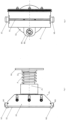
- Fig.1 shows the cleaning nozzle in the axonometric expanded view
- Fig.2 shows a view of the cleaning nozzle from the side of the fitted barrier to aid in screen cleaning
- Fig. 3 shows a view of the cleaning nozzle from the front
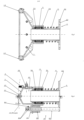
- Fig.4 and Fig.5 show the nozzle in longitudinal sections to illustrate connection of the cleaning nozzle to the elastic assembly.
- the cleaning nozzle for a slotted filter screen with selectivity below 90 ⁇ m in an embodiment consists of body 1 with suction slot 1.1 which forms suction chamber 1.2 and it is fitted flexibly to connection 2 in the form of tube connector 2.1 ending with a fitting flange 2.2 with openings 2.3 for connecting screws, not shown in the figure ( Fig.1 ).
- the body 1 of the cleaning nozzle has a necking from one side toward the connection 2 ( Fig.5 ) and from the other side it has a necking toward the slotted screen indicated by a dashed line in the figure, forming the suction slot 1.1 ( Fig.4 ).
- spacer rollers 1.3 are permanently fitted, arranged axially on both ends of the suction slot 1.1.
- the spacer rollers 1.3 partially extend outside the body 1 of the cleaning nozzle toward the internal surface of the filter screen by a distance of "n" equal to the slot between the suction slot 1.1 of the cleaning nozzle and the internal surface of the filter screen indicated by a dashed line in the figure ( Fig.4 ).
- the width of the suction slot in the body 1 of the cleaning nozzle is equal to the width of 2 to 3 slots in the filter screen, indicated by a dashed line in the figure.
- the body 1 of the cleaning nozzle is connected with barrier 3 to aid in filter screen cleaning, parallel to the suction slot 1.1.
- the barrier 3 to aid in screen cleaning consists of brush 3.1 arranged between linings 3.2, and the aforementioned elements are connected with one another and fitted to the body 1 of the cleaning nozzle through screw connectors 3.3.
- the elastic connection of the body 1 of the cleaning nozzle with the connection 2 is implemented through spring 4 and bush 5 fitted on the tube connector 2.1 of the connection 2 and through guide assembly 6 which is connected on one side with the body 1 of the cleaning nozzle and on the other side it is fitted on the fitting flange 2.2 of the connection 2, parallel to the axis of the tube connector 2.1.
- the bush 5 fitted on the tube connector 2.1 contains internal sealing 5.1 and it is made of plastic.
- the guide assembly 6 consists of bush 6.1 fitted on rod 6.2 in which adjustment holes 6.3 for pin 6.4 are fitted.
- the cleaning nozzle engages with the filter manifold, not shown in the figure, thus enforcing its movement on the internal surface of the filter screen being cleaned.
- the internal surface of the filter screen is the leading surface for the spacer rollers 1.3 which roll on the surface during a cleaning cycle.
- the body 1 of the cleaning nozzle with the slot 1.1 maintains a constant distance from the filter surface being cleaned.
- the spacer rollers 1.3 are pressed to the screen with the body 1 by the spring 4 aligned on the rube connector 2 as an integral part with the fitting flange 2.1.
- the internal sealing 5.1 of the bush 5 separates the space of the "dirty" filter chamber from the suction chamber 1.2 of the body 1 of the cleaning nozzle.
- the body 1 of the cleaning nozzle can freely and axially move along the rod 6.2 owing to holder 6.5 of the guide assembly 6 fitted to the body 1, wherein on the loose end of the rod 6.2 adjustment holes 6.3 for the pin 6.4 are fitted, used to adjust the range of movement and they limit the minimum and maximum distance of the suction slot 1.1 from the internal surface of the filter screen.
Landscapes
- Chemical & Material Sciences (AREA)
- Chemical Kinetics & Catalysis (AREA)
- Cleaning In General (AREA)
- Combined Means For Separation Of Solids (AREA)
- Photoreceptors In Electrophotography (AREA)
Claims (9)
- Reinigungsdüse für ein Spaltfiltrationssieb mit einer Selektivität unter 90 µm, die einen Körper, der eine Saugkammer bildet, und einen Anschluss enthält, der zum Anschließen an einen Filterrohrverteiler und eine Bürste zur Unterstützung der Siebreinigung geeignet ist, dadurch gekennzeichnet, dass der Körper (1) der Reinigungsdüse, der die Saugkammer (1.2) mit einem Saugschlitz (1.1) bildet, flexibel mit dem Anschluss (2) in Form eines Rohrverbinders (2.1) verbunden ist, der mit einem Anschlussflansch (2.2) endet, wobei die flexible Verbindung mit dem Rohrverbinder (2.1) in Form einer Feder (4), die an dem Rohrverbinder (2.1) zwischen dem Anschlussflansch (2.2) und einer Buchse (5) angebracht ist, und durch eine Führungseinheit (6), die auf einer Seite mit dem Reinigungsdüsenkörper (1) verbunden und auf der anderen Seite auf dem Anschlussflansch (2.2) parallel zur Achse des Rohrverbinders (2.1) angebracht ist, und Abstandsrollen (1.3) sind im Körper der Reinigungsdüse (1) von der Seite der Saugschlitzes (1.1) her dauerhaft befestigt und erstrecken sich teilweise vom Körper (1) in Richtung der Innenfläche des Filtersiebs.
- Reinigungsdüse nach Anspruch 1, dadurch gekennzeichnet, dass der Körper (1) der Reinigungsdüse auf der einen Seite eine Einschnürung in Richtung des Anschlusses (2) und auf der anderen Seite eine Einschnürung in Richtung des Spaltsiebs aufweist, wobei der Saugschlitz (1. 1) erhalten bleibt.
- Reinigungsdüse nach Anspruch 1 oder 2, dadurch gekennzeichnet, dass die Breite des Saugschlitzes (1.1) im Körper der Reinigungsdüse der Breite von 2 bis 3 Schlitzen in dem mit der Reinigungsdüse zusammenpassenden Filtersieb entspricht.
- Reinigungsdüse nach Anspruch 1, dadurch gekennzeichnet, dass die Bürste (3.1) zur Unterstützung der Siebreinigung zwischen Auskleidungen (3.2) angeordnet ist, die eine Barriere (3) bilden, die lösbar mit dem Körper (1) der Reinigungsdüse verbunden ist, wobei die Barriere (3) parallel zu dem Saugschlitz (1.1) angebracht ist.
- Reinigungsdüse nach Anspruch 4, dadurch gekennzeichnet, dass die Barriere (3) mit Hilfe von Schraubverbindungen (3.3) am Körper (1) der Reinigungsdüse angebracht ist.
- Reinigungsdüse nach Anspruch 4, dadurch gekennzeichnet, dass die Barriere (3) zur Unterstützung der Siebreinigung eine Länge aufweist, die dem Saugschlitz (1.1) entspricht.
- Reinigungsdüse nach Anspruch 1, dadurch gekennzeichnet, dass sich die Abstandsrollen (1.3) teilweise außerhalb des Reinigungsdüsenkörpers um einen Abstand "n" erstrecken, der gleich dem Schlitz zwischen dem Saugschlitz (1.1) und der Innenfläche des Filtersiebs ist.
- Reinigungsdüse nach Anspruch 1, dadurch gekennzeichnet, dass die auf den Rohrverbindern (2.1) aufgesetzte Buchse (5) eine innere Dichtung (5.1) aufweist.
- Reinigungsdüse nach Anspruch 1, dadurch gekennzeichnet, dass die Führungseinheit (6) aus einer Buchse (6.1) besteht, die auf einer Stange (6.2) angebracht ist, in der Einstelllöcher (6.3) für einen Stift (6.4) angebracht sind.
Applications Claiming Priority (1)
| Application Number | Priority Date | Filing Date | Title |
|---|---|---|---|
| PL439708A PL439708A1 (pl) | 2021-12-01 | 2021-12-01 | Dysza czyszcząca do sita filtracyjnego szczelinowego, o selektywności poniżej 90 μm |
Publications (3)
| Publication Number | Publication Date |
|---|---|
| EP4190425A1 EP4190425A1 (de) | 2023-06-07 |
| EP4190425B1 true EP4190425B1 (de) | 2025-02-12 |
| EP4190425B8 EP4190425B8 (de) | 2025-03-19 |
Family
ID=84535970
Family Applications (1)
| Application Number | Title | Priority Date | Filing Date |
|---|---|---|---|
| EP22460063.5A Active EP4190425B8 (de) | 2021-12-01 | 2022-11-22 | Reinigungsdüse für ein geschlitztes filtersieb mit selektivität unter 90 mikrometer |
Country Status (2)
| Country | Link |
|---|---|
| EP (1) | EP4190425B8 (de) |
| PL (2) | PL439708A1 (de) |
Family Cites Families (9)
| Publication number | Priority date | Publication date | Assignee | Title |
|---|---|---|---|---|
| US3635348A (en) * | 1970-06-09 | 1972-01-18 | Kinney Eng Inc S P | Automatic self-cleaning strainers |
| PL109554B1 (en) | 1977-06-11 | 1980-06-30 | Zjednoczone Zaklady Produkcji | Big input impedance transistor amplifier |
| DE3611075A1 (de) * | 1986-04-03 | 1987-10-08 | Boll & Kirch Filter | Rueckspuelfilter |
| PL198799B1 (pl) * | 2002-11-25 | 2008-07-31 | Wytwornia Sit Progress Spo & L | Filtr samooczyszczający się |
| AU2004321592A1 (en) * | 2004-07-21 | 2006-01-26 | Amiad Filtration Systems (1997) Ltd. | Filter cleaning head |
| DE102009010255B4 (de) * | 2009-02-24 | 2013-01-17 | Dango & Dienenthal Filtertechnik Gmbh | Flüssigkeitsfilter |
| IT201800003030A1 (it) * | 2018-02-26 | 2019-08-26 | Serenambiente S R L | Filtro autopulente |
| JP2020114577A (ja) * | 2019-01-17 | 2020-07-30 | 三浦工業株式会社 | 水処理装置 |
| KR20210058124A (ko) * | 2019-11-13 | 2021-05-24 | 노준식 | 역세척 기능을 구비한 필터장치 |
-
2021
- 2021-12-01 PL PL439708A patent/PL439708A1/pl unknown
-
2022
- 2022-11-22 EP EP22460063.5A patent/EP4190425B8/de active Active
- 2022-11-22 PL PL22460063.5T patent/PL4190425T3/pl unknown
Also Published As
| Publication number | Publication date |
|---|---|
| EP4190425B8 (de) | 2025-03-19 |
| PL439708A1 (pl) | 2023-06-05 |
| EP4190425A1 (de) | 2023-06-07 |
| PL4190425T3 (pl) | 2025-05-26 |
Similar Documents
| Publication | Publication Date | Title |
|---|---|---|
| US10751764B2 (en) | Filter cleaning system with a movable proximity nozzle | |
| US5152891A (en) | Self-cleaning strainer | |
| KR20070087546A (ko) | 여과기 청소 헤드 | |
| KR101493135B1 (ko) | 자체-세척 필터 모듈 | |
| US4624785A (en) | Easily-cleanable filters | |
| CN111790198B (zh) | 清洁尤其导水家用器具膜片元件的系统、刮拭元件及方法 | |
| CA2933519A1 (en) | High-efficiency automatic self-cleaning strainer | |
| US6543624B1 (en) | Back-washable filter for liquids | |
| US5098565A (en) | Filter apparatus | |
| GB2500900A (en) | Filter cleaning | |
| EP3077074A1 (de) | Filtrationssystem und filteranordnung damit | |
| CN109847489B (zh) | 一种除尘器 | |
| EP4190425B1 (de) | Reinigungsdüse für ein geschlitztes filtersieb mit selektivität unter 90 mikrometer | |
| US5213684A (en) | Filter apparatus | |
| CN101778660B (zh) | 过滤系统用反冲装置 | |
| CN222368472U (zh) | 一种直饮水入户前置过滤装置 | |
| EP3723885B1 (de) | Saugadapter für filtersiebe | |
| USRE34218E (en) | Easily-cleanable filters | |
| US20250099884A1 (en) | Filter system with backflush | |
| DE10252679B4 (de) | Selbstreinigendes Flüssigkeitsfilter | |
| CN219654898U (zh) | 一种抽水泵 | |
| CN220452373U (zh) | 一种带双辅助供油过滤通道的油缸 | |
| CN222400528U (zh) | 一种弹性吸嘴以及过滤器 | |
| CN120532185B (zh) | 一种用于固体和流体分离的过滤装置 | |
| CN220505397U (zh) | 一种多级给水泵 |
Legal Events
| Date | Code | Title | Description |
|---|---|---|---|
| PUAI | Public reference made under article 153(3) epc to a published international application that has entered the european phase |
Free format text: ORIGINAL CODE: 0009012 |
|
| STAA | Information on the status of an ep patent application or granted ep patent |
Free format text: STATUS: THE APPLICATION HAS BEEN PUBLISHED |
|
| AK | Designated contracting states |
Kind code of ref document: A1 Designated state(s): AL AT BE BG CH CY CZ DE DK EE ES FI FR GB GR HR HU IE IS IT LI LT LU LV MC ME MK MT NL NO PL PT RO RS SE SI SK SM TR |
|
| STAA | Information on the status of an ep patent application or granted ep patent |
Free format text: STATUS: REQUEST FOR EXAMINATION WAS MADE |
|
| 17P | Request for examination filed |
Effective date: 20231031 |
|
| RBV | Designated contracting states (corrected) |
Designated state(s): AL AT BE BG CH CY CZ DE DK EE ES FI FR GB GR HR HU IE IS IT LI LT LU LV MC ME MK MT NL NO PL PT RO RS SE SI SK SM TR |
|
| R17P | Request for examination filed (corrected) |
Effective date: 20231031 |
|
| GRAP | Despatch of communication of intention to grant a patent |
Free format text: ORIGINAL CODE: EPIDOSNIGR1 |
|
| STAA | Information on the status of an ep patent application or granted ep patent |
Free format text: STATUS: GRANT OF PATENT IS INTENDED |
|
| GRAJ | Information related to disapproval of communication of intention to grant by the applicant or resumption of examination proceedings by the epo deleted |
Free format text: ORIGINAL CODE: EPIDOSDIGR1 |
|
| STAA | Information on the status of an ep patent application or granted ep patent |
Free format text: STATUS: REQUEST FOR EXAMINATION WAS MADE |
|
| GRAP | Despatch of communication of intention to grant a patent |
Free format text: ORIGINAL CODE: EPIDOSNIGR1 |
|
| STAA | Information on the status of an ep patent application or granted ep patent |
Free format text: STATUS: GRANT OF PATENT IS INTENDED |
|
| RIC1 | Information provided on ipc code assigned before grant |
Ipc: B01D 29/68 20060101ALI20240826BHEP Ipc: B01D 29/64 20060101ALI20240826BHEP Ipc: B01D 29/35 20060101AFI20240826BHEP |
|
| INTG | Intention to grant announced |
Effective date: 20240913 |
|
| INTC | Intention to grant announced (deleted) | ||
| INTG | Intention to grant announced |
Effective date: 20240925 |
|
| GRAS | Grant fee paid |
Free format text: ORIGINAL CODE: EPIDOSNIGR3 |
|
| GRAA | (expected) grant |
Free format text: ORIGINAL CODE: 0009210 |
|
| STAA | Information on the status of an ep patent application or granted ep patent |
Free format text: STATUS: THE PATENT HAS BEEN GRANTED |
|
| AK | Designated contracting states |
Kind code of ref document: B1 Designated state(s): AL AT BE BG CH CY CZ DE DK EE ES FI FR GB GR HR HU IE IS IT LI LT LU LV MC ME MK MT NL NO PL PT RO RS SE SI SK SM TR |
|
| RAP3 | Party data changed (applicant data changed or rights of an application transferred) |
Owner name: PFTECHNOLOGY SPOLKA Z OGRANICZONAODPOWIEDZIALNOSCIA |
|
| REG | Reference to a national code |
Ref country code: GB Ref legal event code: FG4D Ref country code: DE Ref legal event code: R081 Ref document number: 602022010491 Country of ref document: DE Owner name: PFTECHNOLOGY SPOLKA Z OGRANICZONA ODPOWIEDZIAL, PL Free format text: FORMER OWNER: PFTECHNOLOGY SPOLKA Z OGRANICZONA ODPOWIEDZIALNOSCIA, WARSZAWA, PL |
|
| REG | Reference to a national code |
Ref country code: CH Ref legal event code: EP |
|
| REG | Reference to a national code |
Ref country code: CH Ref legal event code: PK Free format text: BERICHTIGUNG B8 |
|
| RAP4 | Party data changed (patent owner data changed or rights of a patent transferred) |
Owner name: PFTECHNOLOGY SPOLKA Z OGRANICZONAODPOWIEDZIALNOSCIA |
|
| REG | Reference to a national code |
Ref country code: DE Ref legal event code: R096 Ref document number: 602022010491 Country of ref document: DE |
|
| REG | Reference to a national code |
Ref country code: IE Ref legal event code: FG4D |
|
| REG | Reference to a national code |
Ref country code: NL Ref legal event code: MP Effective date: 20250212 |
|
| PG25 | Lapsed in a contracting state [announced via postgrant information from national office to epo] |
Ref country code: RS Free format text: LAPSE BECAUSE OF FAILURE TO SUBMIT A TRANSLATION OF THE DESCRIPTION OR TO PAY THE FEE WITHIN THE PRESCRIBED TIME-LIMIT Effective date: 20250512 |
|
| PG25 | Lapsed in a contracting state [announced via postgrant information from national office to epo] |
Ref country code: FI Free format text: LAPSE BECAUSE OF FAILURE TO SUBMIT A TRANSLATION OF THE DESCRIPTION OR TO PAY THE FEE WITHIN THE PRESCRIBED TIME-LIMIT Effective date: 20250212 |
|
| PG25 | Lapsed in a contracting state [announced via postgrant information from national office to epo] |
Ref country code: ES Free format text: LAPSE BECAUSE OF FAILURE TO SUBMIT A TRANSLATION OF THE DESCRIPTION OR TO PAY THE FEE WITHIN THE PRESCRIBED TIME-LIMIT Effective date: 20250212 |
|
| REG | Reference to a national code |
Ref country code: LT Ref legal event code: MG9D |
|
| PG25 | Lapsed in a contracting state [announced via postgrant information from national office to epo] |
Ref country code: NO Free format text: LAPSE BECAUSE OF FAILURE TO SUBMIT A TRANSLATION OF THE DESCRIPTION OR TO PAY THE FEE WITHIN THE PRESCRIBED TIME-LIMIT Effective date: 20250512 Ref country code: IS Free format text: LAPSE BECAUSE OF FAILURE TO SUBMIT A TRANSLATION OF THE DESCRIPTION OR TO PAY THE FEE WITHIN THE PRESCRIBED TIME-LIMIT Effective date: 20250612 |
|
| PG25 | Lapsed in a contracting state [announced via postgrant information from national office to epo] |
Ref country code: NL Free format text: LAPSE BECAUSE OF FAILURE TO SUBMIT A TRANSLATION OF THE DESCRIPTION OR TO PAY THE FEE WITHIN THE PRESCRIBED TIME-LIMIT Effective date: 20250212 |
|
| PG25 | Lapsed in a contracting state [announced via postgrant information from national office to epo] |
Ref country code: HR Free format text: LAPSE BECAUSE OF FAILURE TO SUBMIT A TRANSLATION OF THE DESCRIPTION OR TO PAY THE FEE WITHIN THE PRESCRIBED TIME-LIMIT Effective date: 20250212 |
|
| PG25 | Lapsed in a contracting state [announced via postgrant information from national office to epo] |
Ref country code: LV Free format text: LAPSE BECAUSE OF FAILURE TO SUBMIT A TRANSLATION OF THE DESCRIPTION OR TO PAY THE FEE WITHIN THE PRESCRIBED TIME-LIMIT Effective date: 20250212 Ref country code: PT Free format text: LAPSE BECAUSE OF FAILURE TO SUBMIT A TRANSLATION OF THE DESCRIPTION OR TO PAY THE FEE WITHIN THE PRESCRIBED TIME-LIMIT Effective date: 20250612 |
|
| PG25 | Lapsed in a contracting state [announced via postgrant information from national office to epo] |
Ref country code: GR Free format text: LAPSE BECAUSE OF FAILURE TO SUBMIT A TRANSLATION OF THE DESCRIPTION OR TO PAY THE FEE WITHIN THE PRESCRIBED TIME-LIMIT Effective date: 20250513 Ref country code: BG Free format text: LAPSE BECAUSE OF FAILURE TO SUBMIT A TRANSLATION OF THE DESCRIPTION OR TO PAY THE FEE WITHIN THE PRESCRIBED TIME-LIMIT Effective date: 20250212 |
|
| PG25 | Lapsed in a contracting state [announced via postgrant information from national office to epo] |
Ref country code: SE Free format text: LAPSE BECAUSE OF FAILURE TO SUBMIT A TRANSLATION OF THE DESCRIPTION OR TO PAY THE FEE WITHIN THE PRESCRIBED TIME-LIMIT Effective date: 20250212 |
|
| PG25 | Lapsed in a contracting state [announced via postgrant information from national office to epo] |
Ref country code: SM Free format text: LAPSE BECAUSE OF FAILURE TO SUBMIT A TRANSLATION OF THE DESCRIPTION OR TO PAY THE FEE WITHIN THE PRESCRIBED TIME-LIMIT Effective date: 20250212 |
|
| PG25 | Lapsed in a contracting state [announced via postgrant information from national office to epo] |
Ref country code: DK Free format text: LAPSE BECAUSE OF FAILURE TO SUBMIT A TRANSLATION OF THE DESCRIPTION OR TO PAY THE FEE WITHIN THE PRESCRIBED TIME-LIMIT Effective date: 20250212 |
|
| PGFP | Annual fee paid to national office [announced via postgrant information from national office to epo] |
Ref country code: PL Payment date: 20250716 Year of fee payment: 4 |
|
| PG25 | Lapsed in a contracting state [announced via postgrant information from national office to epo] |
Ref country code: CZ Free format text: LAPSE BECAUSE OF FAILURE TO SUBMIT A TRANSLATION OF THE DESCRIPTION OR TO PAY THE FEE WITHIN THE PRESCRIBED TIME-LIMIT Effective date: 20250212 |
|
| PG25 | Lapsed in a contracting state [announced via postgrant information from national office to epo] |
Ref country code: RO Free format text: LAPSE BECAUSE OF FAILURE TO SUBMIT A TRANSLATION OF THE DESCRIPTION OR TO PAY THE FEE WITHIN THE PRESCRIBED TIME-LIMIT Effective date: 20250212 |
|
| PG25 | Lapsed in a contracting state [announced via postgrant information from national office to epo] |
Ref country code: SK Free format text: LAPSE BECAUSE OF FAILURE TO SUBMIT A TRANSLATION OF THE DESCRIPTION OR TO PAY THE FEE WITHIN THE PRESCRIBED TIME-LIMIT Effective date: 20250212 |
|
| REG | Reference to a national code |
Ref country code: DE Ref legal event code: R097 Ref document number: 602022010491 Country of ref document: DE |
|
| PLBE | No opposition filed within time limit |
Free format text: ORIGINAL CODE: 0009261 |
|
| STAA | Information on the status of an ep patent application or granted ep patent |
Free format text: STATUS: NO OPPOSITION FILED WITHIN TIME LIMIT |
|
| PGFP | Annual fee paid to national office [announced via postgrant information from national office to epo] |
Ref country code: DE Payment date: 20251113 Year of fee payment: 4 |
|
| PGFP | Annual fee paid to national office [announced via postgrant information from national office to epo] |
Ref country code: AT Payment date: 20260113 Year of fee payment: 4 |
|
| PGFP | Annual fee paid to national office [announced via postgrant information from national office to epo] |
Ref country code: IT Payment date: 20251201 Year of fee payment: 4 |
|
| PGFP | Annual fee paid to national office [announced via postgrant information from national office to epo] |
Ref country code: FR Payment date: 20251112 Year of fee payment: 4 |
|
| PGFP | Annual fee paid to national office [announced via postgrant information from national office to epo] |
Ref country code: BE Payment date: 20251113 Year of fee payment: 4 |
|
| PGFP | Annual fee paid to national office [announced via postgrant information from national office to epo] |
Ref country code: IE Payment date: 20251112 Year of fee payment: 4 |
|
| 26N | No opposition filed |
Effective date: 20251113 |