EP3724968B1 - Statorsegment - Google Patents
Statorsegment Download PDFInfo
- Publication number
- EP3724968B1 EP3724968B1 EP19706894.3A EP19706894A EP3724968B1 EP 3724968 B1 EP3724968 B1 EP 3724968B1 EP 19706894 A EP19706894 A EP 19706894A EP 3724968 B1 EP3724968 B1 EP 3724968B1
- Authority
- EP
- European Patent Office
- Prior art keywords
- stator
- coil
- stator segment
- groove
- segment
- Prior art date
- Legal status (The legal status is an assumption and is not a legal conclusion. Google has not performed a legal analysis and makes no representation as to the accuracy of the status listed.)
- Active
Links
Images

Classifications
-
- H—ELECTRICITY
- H02—GENERATION; CONVERSION OR DISTRIBUTION OF ELECTRIC POWER
- H02K—DYNAMO-ELECTRIC MACHINES
- H02K3/00—Details of windings
- H02K3/46—Fastening of windings on the stator or rotor structure
- H02K3/48—Fastening of windings on the stator or rotor structure in slots
-
- F—MECHANICAL ENGINEERING; LIGHTING; HEATING; WEAPONS; BLASTING
- F03—MACHINES OR ENGINES FOR LIQUIDS; WIND, SPRING, OR WEIGHT MOTORS; PRODUCING MECHANICAL POWER OR A REACTIVE PROPULSIVE THRUST, NOT OTHERWISE PROVIDED FOR
- F03D—WIND MOTORS
- F03D9/00—Adaptations of wind motors for special use; Combinations of wind motors with apparatus driven thereby; Wind motors specially adapted for installation in particular locations
- F03D9/20—Wind motors characterised by the driven apparatus
- F03D9/25—Wind motors characterised by the driven apparatus the apparatus being an electrical generator
-
- H—ELECTRICITY
- H02—GENERATION; CONVERSION OR DISTRIBUTION OF ELECTRIC POWER
- H02K—DYNAMO-ELECTRIC MACHINES
- H02K1/00—Details of the magnetic circuit
- H02K1/06—Details of the magnetic circuit characterised by the shape, form or construction
- H02K1/12—Stationary parts of the magnetic circuit
- H02K1/20—Stationary parts of the magnetic circuit with channels or ducts for flow of cooling medium
-
- H—ELECTRICITY
- H02—GENERATION; CONVERSION OR DISTRIBUTION OF ELECTRIC POWER
- H02K—DYNAMO-ELECTRIC MACHINES
- H02K3/00—Details of windings
- H02K3/04—Windings characterised by the conductor shape, form or construction, e.g. with bar conductors
- H02K3/24—Windings characterised by the conductor shape, form or construction, e.g. with bar conductors with channels or ducts for cooling medium between the conductors
-
- H—ELECTRICITY
- H02—GENERATION; CONVERSION OR DISTRIBUTION OF ELECTRIC POWER
- H02K—DYNAMO-ELECTRIC MACHINES
- H02K7/00—Arrangements for handling mechanical energy structurally associated with dynamo-electric machines, e.g. structural association with mechanical driving motors or auxiliary dynamo-electric machines
- H02K7/18—Structural association of electric generators with mechanical driving motors, e.g. with turbines
- H02K7/1807—Rotary generators
- H02K7/1823—Rotary generators structurally associated with turbines or similar engines
- H02K7/183—Rotary generators structurally associated with turbines or similar engines wherein the turbine is a wind turbine
- H02K7/1838—Generators mounted in a nacelle or similar structure of a horizontal axis wind turbine
-
- H—ELECTRICITY
- H02—GENERATION; CONVERSION OR DISTRIBUTION OF ELECTRIC POWER
- H02K—DYNAMO-ELECTRIC MACHINES
- H02K9/00—Arrangements for cooling or ventilating
- H02K9/02—Arrangements for cooling or ventilating by ambient air flowing through the machine
- H02K9/04—Arrangements for cooling or ventilating by ambient air flowing through the machine having means for generating a flow of cooling medium
-
- H—ELECTRICITY
- H02—GENERATION; CONVERSION OR DISTRIBUTION OF ELECTRIC POWER
- H02K—DYNAMO-ELECTRIC MACHINES
- H02K2213/00—Specific aspects, not otherwise provided for and not covered by codes H02K2201/00 - H02K2211/00
- H02K2213/12—Machines characterised by the modularity of some components
-
- Y—GENERAL TAGGING OF NEW TECHNOLOGICAL DEVELOPMENTS; GENERAL TAGGING OF CROSS-SECTIONAL TECHNOLOGIES SPANNING OVER SEVERAL SECTIONS OF THE IPC; TECHNICAL SUBJECTS COVERED BY FORMER USPC CROSS-REFERENCE ART COLLECTIONS [XRACs] AND DIGESTS
- Y02—TECHNOLOGIES OR APPLICATIONS FOR MITIGATION OR ADAPTATION AGAINST CLIMATE CHANGE
- Y02E—REDUCTION OF GREENHOUSE GAS [GHG] EMISSIONS, RELATED TO ENERGY GENERATION, TRANSMISSION OR DISTRIBUTION
- Y02E10/00—Energy generation through renewable energy sources
- Y02E10/70—Wind energy
- Y02E10/72—Wind turbines with rotation axis in wind direction
Definitions
- the invention relates to a stator segment, a stator and a generator, in particular of a wind power plant.
- stator of a high-pole, multi-phase electrical machine is known, the stator being divided into several segments and a multi-phase winding being located on each segment.
- US4330726A discloses a stator divided into multiple segments.
- the object of the invention is to provide toothed coils in correspondingly designed stator segments, which can be fixed in a precise position during the manufacturing and assembly process.
- stator segment of a stator of a dynamoelectric machine according to independent claim 1.
- stator with stator segments according to the invention the mutually facing open slots being fastened to one another via fastening means on the yoke backs of the stator segments.
- the object is also achieved by a dynamoelectric machine, in particular a generator of a wind turbine, with a stator according to the invention, with a cooling system, in particular a fan, being provided through which cooling air can be conveyed into the existing gaps between the partial laminated cores.
- the outer coil leg is fixed at the end of the stator segment by non-magnetic fastening means.
- These non-magnetic fasteners prevent heating up caused by eddy currents during operation of the dynamoelectric machine, e.g. the wind power generator.
- the fixation of the outer coil legs in particular during the manufacturing process, here above all the impregnation process, but also during the assembly process, ensures that the coil leg does not move away from the tooth forming an open groove and thus impair the assembly or further manufacturing steps .
- the non-magnetic fastening means are implemented in particular by non-magnetic cable ties, cords or straps, which is a problem in the manufacturing process fast and unproblematic fixing guaranteed by inexpensive standard parts.
- these non-magnetic fastening means, in particular cable ties ensure a permanently strong fixation of the coil legs on the outer teeth, which is also advantageous in particular for longer storage times of such segments.
- Spacers are provided between the partial laminations of the laminations of the stator segment, which on the one hand space the partial laminations from one another, form radial cooling channels within the laminations of the stator segment and thus the stator, and also serve as a holding device for the non-magnetic fastening means for fixing the coil legs to the groove side wall.
- the maximum radial extent of the spacers is as high as the back of the yoke and the radial tooth height together. Normally, the spacers will protrude into the area of the back of the yoke and will not take up the maximum tooth height.
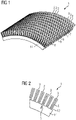
- FIG 1 shows a stator segment 1 of a dynamoelectric machine 11, in particular a generator with an external rotor, which can be seen in the fact that the slots 2 of this stator segment 1 protrude radially outward in the form of spikes and the stator segment 1 is convex.
- the stator segment 1 is constructed in the axial direction from individual partial laminated cores 9 which are spaced apart from one another by spacers 5 .
- Each partial laminated core 9 has a predetermined number of laminations 8 . This packaging of the stator segment 1 facilitates radial cooling of the stator 15 when the stator segment 1 or a composite stator 15 is used in a wind turbine 12 of a generator.
- Formed coils in particular toothed coils 4, are used in slots 2 of the stator segment 1, each comprising a tooth 3 or a plurality of teeth.
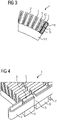
- FIG 2 shows a detailed view of an edge region of a stator segment 1 with its radially outward-pointing teeth 3, the slots 2 and the indicated spacers 5 between the partial laminated cores 9.
- the width of the spacers 5 is significantly smaller than the width of a tooth 3.
- this configuration forms cooling channels of the stator segment 1 with a comparatively large cross section.
- the spacer 5 extends in the radial direction to the yoke back 14 or, for mechanical reasons, to the yoke back 14 of the stator segment 1.
- the spacers 5 are maximally as high in their radial extent as the yoke back 14 and the radial tooth height together. Normally, the spacers 5 will protrude into the area of the yoke back 14 and will not take up the maximum tooth height, as is the case with a tooth 3 of the FIG 2 is shown.
- a groove 2 is made up of groove side walls and a groove base. Accordingly, a groove is referred to as an open groove 13 which has only one groove side wall and at least part of the groove base.
- the slots 2 , 13 are aligned essentially parallel to an axis 16 of a stator 15 .
- a non-magnetic cable tie 6 is provided on the spacers 5, which extend in the gap 7, ie the axial distance between the partial laminated cores 9.
- the non-magnetic cable tie 6 is placed around the outer coil leg 10 of a toothed coil 4 located in the open slot 13 .
- the outer coil leg 10 is thus fixed to the spacer 5 by means of the non-magnetic cable tie 6, which in turn is wedged between the partial laminated cores 9 and fixed there. This also facilitates the impregnation in the production process, since a "movable outer coil leg 10" is avoided.
- the non-magnetic cable tie 6 can also only encompass sections of the spacer 5 and the coil 4, without impairing the desired fixation of the coil 4 on the tooth.
- the cable ties 6 can be threaded through these recesses. This reduces the scope of wrapping, so that shorter cable ties 6 can also be used.
- Such a non-magnetic cable tie 6 is provided on one or more spacers 5 for fixing the coil leg 10 in the described stator segments 1 .
- the cable ties 6 are located, for example, only on one or on each spacer 5 or on every second spacer 5.
- FIG 4 shown how the positioning of the coil 4 takes place on the last tooth of the stator segment 1.
- the spacer 5 between the partial laminated cores 9 is not yet provided with a non-magnetic cable tie 6 .
- the outer coil leg 10 would possibly move away from the tooth 3 in the further manufacturing process or even during the assembly of the stator segments 1 to form a stator 15 .
- FIG. 6 shows a cross section of the above illustration, the arrangement of the coil 4 on the last, ie outer tooth 3, whereby the winding system of this stator segment 1 can be constructed in such a way that a tooth coil 4 is provided around each tooth 3. This means that two different coil sides of different coils 4 are present in each slot.
- Each coil leg located in an open groove 13 is fixed by one or more cable ties 6 , preferably arranged axially distributed, on the outer tooth or on the groove side wall of the open groove 13 in the area of the spacers 5 .
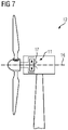
- stator segments 1 are preferred for stators 15 for high power and / or direct drives, especially in wind turbines 12 according to FIG 7 or tube mills are provided.
- a rotor rotates about an axis 16, with the slots 2 of the stator segment 1 and the stator 15 being aligned essentially parallel to the axis.
- a fan can generate a cooling flow 17 that cools at least the generator and/or converter components, in particular the stator 15 , via the radial cooling channels in the stator segment 1 generated by the spacers 5 .
Landscapes
- Engineering & Computer Science (AREA)
- Power Engineering (AREA)
- Life Sciences & Earth Sciences (AREA)
- Sustainable Energy (AREA)
- Sustainable Development (AREA)
- Chemical & Material Sciences (AREA)
- Combustion & Propulsion (AREA)
- Mechanical Engineering (AREA)
- General Engineering & Computer Science (AREA)
- Iron Core Of Rotating Electric Machines (AREA)
- Windings For Motors And Generators (AREA)
- Manufacture Of Motors, Generators (AREA)
- Polishing Bodies And Polishing Tools (AREA)
Description
- Die Erfindung betrifft ein Statorsegment, einen Stator und einen Generator, insbesondere einer Windkraftanlage.
- Aus der
DE 10 2005 029 895 A1 ist ein Direktantrieb für Großantriebe bekannt, der aus mehreren Segmenten aufgebaut ist, die pro Segment eine abgeschlossene Wicklungsanordnung aufweisen. - Aus der
EP 0 718 955 A2 ist ein Stator einer hochpoligen mehrphasigen elektrischen Maschine bekannt, wobei der Stator mehrere Segmente unterteilt ist und sich auf jedem Segment eine mehrphasige Wicklung befindet. -
US4330726A offenbart einen Stator, der in mehrere Segmente unterteilt ist. - Bei segmentierten elektrischen Maschinen, insbesondere Motoren oder Generatoren im höheren Leistungsbereich über 1MW besteht die Möglichkeit das Eisenpaket des Stators so aufzuteilen, dass an den nutparallelen Begrenzungsseiten halbe Nuten vorhanden sind. Erst durch die Montage der einzelnen Segmente wird eine durchgängige Nut und damit eine Wicklung erzeugt. Dies wird beispielsweise bei großen Zahnspulenwicklungen umgesetzt. Problematisch ist dabei die Fixierung der außenliegenden Spulenschenkeln in den halben Nuten insbesondere während des Fertigungsprozesses und Montageprozesses, um während und nach der Imprägnierung den Spulenschenkel an seiner Position zu fixieren.
- Ausgehend davon liegt der Erfindung die Aufgabe zugrunde bei dementsprechend gestalteten Statorsegmenten Zahnspulen vorzusehen, die positionsgenau während des Fertigungs- und Montageprozesses fixierbar sind.
- Die Lösung der gestellten Aufgabe gelingt durch ein Statorsegment eines Stators einer dynamoelektrischen Maschine nach dem unabhängigen Anspruch 1.
- Die Lösung der gestellten Aufgabe gelingt auch durch einen Stator mit erfindungsgemäßen Statorsegmenten, wobei die sich einander zugewandten offenen Nuten über Befestigungsmittel an den Jochrücken der Statorsegmente aneinander befestigt sind.
- Die Lösung der gestellten Aufgabe gelingt auch durch eine dynamoelektrische Maschine, insbesondere einen Generator einer Windkraftanlage, mit einem erfindungsgemäßen Stator wobei ein Kühlsystem, insbesondere ein Lüfter vorgesehen ist, durch das in die vorhandenen Spalte zwischen den Teilblechpaketen Kühlluft förderbar ist.
- Erfindungsgemäß erfolgt die Fixierung des außenliegenden Spulenschenkels am Ende des Statorsegments durch nicht-magnetische Befestigungsmittel. Durch diese nicht-magnetische Befestigungsmittel werden Aufheizungen durch Wirbelströme im Betrieb der dynamoelektrischen Maschine, also z.B. des Windkraftgenerators vermieden. Des Weiteren wird durch die Fixierung der außenliegenden Spulenschenkel, insbesondere während des Fertigungsprozesses, hier vor allem des Imprägnierungsprozesses, aber auch während des Montageprozesses gewährleistet, dass sich der Spulenschenkel nicht von dem, eine offene Nut bildenden Zahn entfernt und somit die Montage oder weitere Fertigungsschritte beeinträchtigt.
- In einer Ausführung werden die amagnetischen Befestigungsmittel, insbesondere durch nicht-magnetische Kabelbinder, Schnüre oder Bänder realisiert, was eine im Fertigungsprozess schnelle und unproblematische Fixierung durch kostengünstige Standardteile gewährleistet. Außerdem ist es vorteilhaft, dass diese nicht-magnetischen Befestigungsmittel, insbesondere Kabelbinder eine dauerhaft starke Fixierung der Spulenschenkel an den außenliegenden Zähnen gewährleisten, was insbesondere auch für längere Lagerzeiten derartiger Segmenten von Vorteil ist.
- Zwischen Teilblechpaketen des Blechpakets des Statorsegments sind Abstandshalter vorgesehen, die zum einen die Teilblechpakete voneinander beabstanden, radiale Kühlkanäle innerhalb des Blechpakets des Statorsegments und damit des Stators bilden, als auch als Haltevorrichtung für die amagnetischen Befestigungsmittel zur Fixierung der Spulenschenkel an der Nutseitenwand dienen.
- Die Abstandshalter sind in ihrer radialen Ausdehnung maximal so hoch wie der Jochrücken und die radiale Zahnhöhe zusammen. Im Normalfall werden die Abstandshalter in den Bereich des Jochrückens ragen und auch nicht die maximale Zahnhöhe einnehmen.
- Die Erfindung sowie weitere vorteilhafte Ausgestaltungen der Erfindung werden anhand prinzipiell dargestellter Ausführungsbeispiele näher erläutert. Darin zeigt:
- FIG 1
- ein Statorsegment,
- FIG 2
- einen Teilausschnitt eines Statorsegments,
- FIG 3
- einen Teilausschnitt eines Statorsegments mit Zahnspule,
- FIG 4
- eine perspektivische Darstellung eines Teilsegments,
- FIG 5
- eine perspektivische Darstellung eines Statorsegments,
- FIG 6
- einen Teilausschnitt eines Statorsegments mit Zahnspule,
- FIG 7
- prinzipiell dargestellte Windkraftanlage.
-
FIG 1 zeigt ein Statorsegment 1 einer dynamoelektrischen Maschine 11, insbesondere eines Generators mit einem Außenläufer, was darin ersichtlich ist, dass die Nuten 2 dieses Statorsegments 1 stachelförmig radial nach außen stehen und das Statorsegment 1 konvex ausgebildet ist. - Das Statorsegment 1 ist in diesem Fall in axialer Richtung aus einzelnen Teilblechpaketen 9 aufgebaut, die durch Abstandshalter 5 voneinander beabstandet sind. Jedes Teilblechpaket 9 weist eine vorgegebene Anzahl von Blechen 8 auf. Diese Paketierung des Statorsegments 1 erleichtert im Einsatzfall des Statorsegments 1 bzw. des eines zusammengesetzten Stators 15 in einer Windkraftanlage 12 eines Generators eine radiale Kühlung des Stators 15.
- In Nuten 2 des Statorsegments 1 sind Formspulen, insbesondere Zahnspulen 4 eingesetzt, die jeweils einen Zahn 3 oder mehrere Zähne umfassen.
-
FIG 2 zeigt eine Detailansicht eines Randbezirks eines Statorsegments 1 mit seinen radial nach außen weisenden Zähnen 3, den Nuten 2 und den angedeuteten Abstandshaltern 5 zwischen den Teilblechpaketen 9. Die Abstandshalter 5 sind in dieser Darstellung in ihrer Breite wesentlich geringer ausgeführt als die Breite eines Zahnes 3. Diese Ausgestaltung bildet, in radialer Richtung betrachtet, Kühlkanäle des Statorsegments 1 mit vergleichsweise großem Querschnitt. Der Abstandshalter 5 erstreckt sich in radialer Richtung bis zum Jochrücken 14 oder aus mechanischen Gründen bis in den Jochrücken 14 des Statorsegments 1. - Die Abstandshalter 5 sind in ihrer radialen Ausdehnung maximal so hoch wie der Jochrücken 14 und die radiale Zahnhöhe zusammen. Im Normalfall werden die Abstandshalter 5 in den Bereich des Jochrückens 14 ragen und auch nicht die maximale Zahnhöhe einnehmen, wie dies beispielhaft an einem Zahn 3 der
FIG 2 gezeigt ist. - An dem äußeren Rand des Statorsegments 1 befindet sich somit nur ein Teil einer Nut 2, die als offene Nut 13 bezeichnet wird, in die ein Spulenschenkel 10 einer Zahnspule 4 oder einer anderen Formspule positioniert ist. Eine Nut 2 setzt sich aus Nutseitenwänden und einem Nutgrund zusammen. Als offene Nut 13 wird demnach eine Nut bezeichnet, die nur eine Nutseitenwand und zumindest einen Teil des Nutgrundes aufweist.
- Die Nuten 2, 13 sind dabei im Wesentlichen parallel zu einer Achse 16 eines Stators 15 ausgerichtet.
- Um nunmehr eine Positioniergenauigkeit und Fixierung dieses Spulenschenkels 10 einer Formspule oder Zahnspule 4 zu erhalten, wird, wie in
FIG 3 dargestellt, an den Abstandshaltern 5, die sich in der Lücke 7, also dem axialen Abstand zwischen den Teilblechpakete 9 erstrecken, ein amagnetischer Kabelbinder 6 vorgesehen. Der amagnetische Kabelbinder 6 wird um den in der offenen Nut 13 befindlichen außenliegenden Spulenschenkel 10 einer Zahnspule 4 gelegt. Damit wird der außenliegende Spulenschenkel 10 mittels des amagnetischen Kabelbinders 6 am Abstandshalter 5 fixiert, der wiederum zwischen die Teilblechpakete 9 eingekeilt und dort fixiert ist. Damit erleichtert sich auch im Fertigungsprozess die Imprägnierung, da ein "sich bewegbarer außenliegenden Spulenschenkels 10" vermieden wird. - In einer perspektivischen Darstellung dieses Außenbereichs gemäß
FIG 4 wird die Positionierung des amagnetischen Kabelbinders 6 in einer radialen Lücke 7 zwischen zwei Teilblechpaketen 9 am Abstandshalter 5 gezeigt. Damit ist der außenliegende Spulenschenkel 10 an dem außenliegenden Zahn fest fixiert. Dieser Zahn bildet mit einer Seite die Nutseitenwand der offenen Nut 13. Der amagnetische Kabelbinder 6 zieht somit den außenliegenden Spulenschenkel 10 an die Nutseitenwand der offenen Nut 13. - Aufgrund zumindest einer Ausnehmung im Abstandhalter 5 und/oder in der Spule 4 im axialen Bereich dieses Abstandhalters 5 kann der amagnetische Kabelbinder 6 auch nur Abschnitte des Abstandhalters 5 und der Spule 4 umgreifen, ohne die angestrebte Fixierung der Spule 4 an den Zahn zu beeinträchtigen. Dabei kann der der Kabelbinder 6 durch diese Ausnehmungen gefädelt werden. Dies verkleinert den Umschlingungsumfang, sodass auch kürzere Kabelbinder 6 eingesetzt werden können.
- Ein derartiger amagnetischer Kabelbinder 6 ist bei den beschriebenen Statorsegmenten 1 an einem oder mehreren Abstandshaltern 5 zur Fixierung des Spulenschenkels 10 vorgesehen. Auf die axiale Länge eines Statorsegments 1 betrachtet befinden sich beispielsweise nur an einem oder an jedem Abstandshalter 5 oder jeden zweiten Abstandshalter 5 die Kabelbinder 6.
- In
FIG 5 ist in einer anderen Darstellung dieser Anordnung gemäßFIG 4 gezeigt, wie die Positionierung der Spule 4 auf dem letzten Zahn des Statorsegments 1 erfolgt. Der Abstandshalter 5 zwischen den Teilblechpaketen 9 ist dabei noch nicht mit einem amagnetischen Kabelbinder 6 versehen. Damit würde sich der außenliegende Spulenschenkel 10 im weiteren Fertigungsprozess oder gar bei der Montage der Statorsegmente 1 zu einem Stator 15 gegebenenfalls vom Zahn 3 wegbewegen. -
FIG 6 zeigt einen Querschnitt der oben genannten Darstellung die Anordnung der Spule 4 auf dem letzten, also äußeren Zahn 3, wobei das Wicklungssystem dieses Statorsegments 1 dadurch so aufgebaut werden kann, dass um jeden Zahn 3 eine Zahnspule 4 vorgesehen wird. Das bedeutet, dass in jeder Nut 2 unterschiedliche Spulenseiten unterschiedlicher Spulen 4 vorhanden sind. - Jeder in einer offenen Nut 13 befindliche Spulenschenkel wird durch einen oder mehrere vorzugsweise axial verteilt angeordnete Kabelbinder 6 am äußeren Zahn bzw. an der Nutseitenwand der offenen Nut 13 im Bereich der Abstandshalter 5 fixiert.
- Eine derartige Anordnung von Statorsegmenten 1 wird bei Statoren 15 bevorzugt, die für große Leistungen und/oder Direktantriebe, insbesondere bei Windkraftanlagen 12 gemäß
FIG 7 oder Rohrmühlen vorgesehen sind. Ein Rotor dreht dabei um eine Achse 16, wobei die Nuten 2 des Statorsegments 1 und des Stators 15 im Wesentlichen achsparallel ausgerichtet sind. - Dabei kann ein Lüfter einen Kühlstrom 17 erzeugen, der zumindest den Generator und/oder Umrichterkomponenten, insbesondere den Stator 15 über die durch die Abstandshalter 5 generierten radialen Kühlkanäle im Statorsegment 1 kühlt.
Claims (3)
- Statorsegment (1) eines Stators (15) einer dynamoelektrischen Maschine (11) mit- axial hintereinander angeordnete genutete Blechen (8), so dass im Wesentlichen axial verlaufende Nuten (2) gebildet sind,- in den Nuten (2) angeordnete Spulen (4), wobei in einer Nut (2) eine Spulenseite oder zwei Spulenseiten unterschiedlicher Spulen (4) angeordnet sind,- wobei die Bleche (8) an ihren nutparallelen äußeren Begrenzungsseiten zumindest eine offene Nut (2) aufweist,- wobei eine offene Nut (13) ein Teil einer Nut (2) an dem äußeren Rand des Statorsegments (1) ist,- wobei die Spulenseiten in den offenen Nuten (13) durch amagnetische Befestigungsmittel an dem Statorsegment (1) fixiert sind,- wobei nach einer vorgebbaren Anzahl von Blechen (8) in axialer Richtung Abstandshalter (5) vorgesehen sind, so dass in axialer Richtung betrachtet zwei oder mehrere Teilblechpakete (9) des Statorsegments (1) vorhanden sind,- wobei die amagnetischen Befestigungsmittel als amagnetische Kabelbinder (6) ausgeführt sind,- wobei die amagnetischen Kabelbinder (6) im Bereich der axial voneinander beabstandeten Bleche (8) angeordnet sind, wobei der Kabelbinder (6) zumindest abschnittsweise um den jeweiligen Abstandshalter (5) geführt ist.
- Stator (15) mit Statorsegmenten (1) nach Anspruch 1, dadurch gekennzeichnet, dass die sich einander zugewandten offenen Nuten (13) zweier Statorsegmente (1) nur mit einem Spulenschenkel eines Statorsegments (1) oder zwei Spulenschenkeln (10) unterschiedlicher aber benachbarter Statorsegmente (1) versehen sind.
- Dynamoelektrische Maschine (11), insbesondere Generator einer Windkraftanlage, mit einem Stator (15) nach Anspruch 2, dadurch gekennzeichnet, dass ein Kühlsystem, insbesondere Lüfter vorgesehen ist, durch das in die vorhandenen Spalte zwischen den Teilblechpaketen (9) Kühlluft förderbar ist.
Applications Claiming Priority (2)
| Application Number | Priority Date | Filing Date | Title |
|---|---|---|---|
| EP18164127.5A EP3547501A1 (de) | 2018-03-27 | 2018-03-27 | Statorsegment |
| PCT/EP2019/052964 WO2019185222A1 (de) | 2018-03-27 | 2019-02-07 | Statorsegment |
Publications (2)
| Publication Number | Publication Date |
|---|---|
| EP3724968A1 EP3724968A1 (de) | 2020-10-21 |
| EP3724968B1 true EP3724968B1 (de) | 2022-06-15 |
Family
ID=61827548
Family Applications (2)
| Application Number | Title | Priority Date | Filing Date |
|---|---|---|---|
| EP18164127.5A Withdrawn EP3547501A1 (de) | 2018-03-27 | 2018-03-27 | Statorsegment |
| EP19706894.3A Active EP3724968B1 (de) | 2018-03-27 | 2019-02-07 | Statorsegment |
Family Applications Before (1)
| Application Number | Title | Priority Date | Filing Date |
|---|---|---|---|
| EP18164127.5A Withdrawn EP3547501A1 (de) | 2018-03-27 | 2018-03-27 | Statorsegment |
Country Status (5)
| Country | Link |
|---|---|
| US (1) | US11349365B2 (de) |
| EP (2) | EP3547501A1 (de) |
| CN (1) | CN111919357B (de) |
| ES (1) | ES2920325T3 (de) |
| WO (1) | WO2019185222A1 (de) |
Families Citing this family (4)
| Publication number | Priority date | Publication date | Assignee | Title |
|---|---|---|---|---|
| EP3863163B1 (de) | 2020-02-06 | 2023-03-29 | Flender GmbH | Statorsegment |
| EP3883090A1 (de) * | 2020-03-19 | 2021-09-22 | Siemens Aktiengesellschaft | Verfahren zum montieren von formspulen oder zahnspulen |
| EP3975386A1 (de) * | 2020-09-25 | 2022-03-30 | Siemens Aktiengesellschaft | Spulenfixierung an halboffenen nuten eines statorsegments |
| EP4012897A1 (de) | 2020-12-14 | 2022-06-15 | Flender GmbH | Verfahren zur fixierung von statorsegmenten einer segmentierten dynamoelektrischen maschine |
Family Cites Families (14)
| Publication number | Priority date | Publication date | Assignee | Title |
|---|---|---|---|---|
| US4330726A (en) * | 1980-12-04 | 1982-05-18 | General Electric Company | Air-gap winding stator construction for dynamoelectric machine |
| JPH0739329Y2 (ja) * | 1986-10-23 | 1995-09-06 | 株式会社東芝 | 回転電機 |
| EP0718955A3 (de) | 1994-12-23 | 1998-03-25 | Siemens Aktiengesellschaft | Ständer für eine hochpolige mehrphasige elektrische Maschine |
| JPH10322975A (ja) * | 1997-05-16 | 1998-12-04 | Hitachi Ltd | 回転電機の通風構造 |
| WO2006084496A1 (de) * | 2005-02-14 | 2006-08-17 | Etel Sa | Elektromotor mit einem aus mehreren blechpaketen gebildeten segmentierten teil und verfahren zum zusammenfügen der blechpakete |
| DE102005029895A1 (de) | 2005-06-27 | 2007-01-04 | Siemens Ag | Direktantrieb für Großantriebe |
| GB2430560A (en) * | 2005-09-22 | 2007-03-28 | Alstom Power Conversion Ltd | Laminated stator for tubular electrical machines |
| CN201022158Y (zh) * | 2006-12-29 | 2008-02-13 | 上海南洋电机有限公司 | 直流电机用带槽楔时的电枢绕组 |
| CN201210631Y (zh) * | 2008-06-10 | 2009-03-18 | 永济新时速电机电器有限责任公司 | 机车用异步牵引电动机 |
| CN201360180Y (zh) * | 2009-01-05 | 2009-12-09 | 环一军 | 一种直绕式交流空调器用塑封电机 |
| CN102005872B (zh) * | 2010-12-15 | 2012-10-03 | 南车株洲电机有限公司 | 定子线圈翻槽工艺及其辅助工装装置 |
| JP5952701B2 (ja) * | 2012-10-04 | 2016-07-13 | ミネベア株式会社 | モータのステータ構造、ブラシレスモータ、およびモータのステータ構造の製造方法 |
| EP2975729A1 (de) | 2014-07-17 | 2016-01-20 | Siemens Aktiengesellschaft | Generator einer Windkraftanlage |
| DE102015225586A1 (de) * | 2015-12-17 | 2017-06-22 | Volkswagen Aktiengesellschaft | Spulenkörper für eine elektrische Spule |
-
2018
- 2018-03-27 EP EP18164127.5A patent/EP3547501A1/de not_active Withdrawn
-
2019
- 2019-02-07 US US16/981,620 patent/US11349365B2/en active Active
- 2019-02-07 CN CN201980022424.9A patent/CN111919357B/zh active Active
- 2019-02-07 ES ES19706894T patent/ES2920325T3/es active Active
- 2019-02-07 EP EP19706894.3A patent/EP3724968B1/de active Active
- 2019-02-07 WO PCT/EP2019/052964 patent/WO2019185222A1/de not_active Ceased
Also Published As
| Publication number | Publication date |
|---|---|
| US11349365B2 (en) | 2022-05-31 |
| CN111919357A (zh) | 2020-11-10 |
| EP3547501A1 (de) | 2019-10-02 |
| WO2019185222A1 (de) | 2019-10-03 |
| ES2920325T3 (es) | 2022-08-02 |
| EP3724968A1 (de) | 2020-10-21 |
| US20210028664A1 (en) | 2021-01-28 |
| CN111919357B (zh) | 2023-06-23 |
Similar Documents
| Publication | Publication Date | Title |
|---|---|---|
| EP1811634B1 (de) | Verbindungsanordnung für die Statorwicklung einer Turbomaschine mit 2 oder mehr parallelen Kreisen | |
| DE112007000661T5 (de) | Sator einer rotierenden elektrischen Maschine mit befestigten Kernnutisolatoren | |
| WO2008092746A1 (de) | Ringmotor | |
| DE102012202735B4 (de) | Dynamoelektrische Maschine mit einer Einschichtbruchlochwicklung | |
| EP3547501A1 (de) | Statorsegment | |
| EP3455921B1 (de) | Synchrongenerator einer getriebelosen windenergieanlage sowie verfahren zum herstellen eines synchrongenerators | |
| EP2523321A1 (de) | Zylindrischer Linearmotor mit geblechtem Ständer | |
| WO2018050318A1 (de) | Rotor für eine elektrische rotierende maschine | |
| EP3326264A1 (de) | Ringstator, generator, sowie windenergieanlage mit demselben | |
| DE102012214523A1 (de) | Ständer oder Ständersegment einer dynamoelektrischen Maschine mit optimiertem Wickelkopf | |
| EP3817195A1 (de) | Rotor für eine elektrische maschine, zugehöriges herstellungsverfahren und elektrische maschine zum antreiben eines fahrzeugs | |
| DE102020101023A1 (de) | Spule, Verfahren zur Herstellung einer Spule und elektrische Rotationsmaschine | |
| EP4012897A1 (de) | Verfahren zur fixierung von statorsegmenten einer segmentierten dynamoelektrischen maschine | |
| WO2019149508A1 (de) | Rotor mit kühlkanälen | |
| EP3183799B1 (de) | Aktivteil einer elektrischen maschine | |
| EP3975386A1 (de) | Spulenfixierung an halboffenen nuten eines statorsegments | |
| EP3863163B1 (de) | Statorsegment | |
| DE102011054046A1 (de) | Spulendistanzblock einer dynamoelektrischen Maschine mit einer Strömungsablenkstruktur auf seiner spulenseitigen Oberfläche | |
| EP2975729A1 (de) | Generator einer Windkraftanlage | |
| WO2014166817A2 (de) | Synchrongenerator-polpaket | |
| EP2871752B1 (de) | Läufer einer rotatorischen permanenterregten Synchronmaschine | |
| DE102009001543A1 (de) | Elektrische Maschine und Verfahren zur Herstellung einer elektrischen Maschine | |
| DE102009017870B4 (de) | Stator für einen Gleichstrommotor | |
| DE102018007554B4 (de) | Stator einer drehenden elektrischen maschine und drehende elektrische maschine | |
| DE102010028869A1 (de) | Dynamoelektrische Maschine mit einer Einschichtwicklung für Großantriebe |
Legal Events
| Date | Code | Title | Description |
|---|---|---|---|
| STAA | Information on the status of an ep patent application or granted ep patent |
Free format text: STATUS: UNKNOWN |
|
| STAA | Information on the status of an ep patent application or granted ep patent |
Free format text: STATUS: THE INTERNATIONAL PUBLICATION HAS BEEN MADE |
|
| PUAI | Public reference made under article 153(3) epc to a published international application that has entered the european phase |
Free format text: ORIGINAL CODE: 0009012 |
|
| STAA | Information on the status of an ep patent application or granted ep patent |
Free format text: STATUS: REQUEST FOR EXAMINATION WAS MADE |
|
| 17P | Request for examination filed |
Effective date: 20200715 |
|
| AK | Designated contracting states |
Kind code of ref document: A1 Designated state(s): AL AT BE BG CH CY CZ DE DK EE ES FI FR GB GR HR HU IE IS IT LI LT LU LV MC MK MT NL NO PL PT RO RS SE SI SK SM TR |
|
| AX | Request for extension of the european patent |
Extension state: BA ME |
|
| RAP1 | Party data changed (applicant data changed or rights of an application transferred) |
Owner name: FLENDER GMBH |
|
| DAV | Request for validation of the european patent (deleted) | ||
| DAX | Request for extension of the european patent (deleted) | ||
| GRAP | Despatch of communication of intention to grant a patent |
Free format text: ORIGINAL CODE: EPIDOSNIGR1 |
|
| STAA | Information on the status of an ep patent application or granted ep patent |
Free format text: STATUS: GRANT OF PATENT IS INTENDED |
|
| INTG | Intention to grant announced |
Effective date: 20220301 |
|
| GRAS | Grant fee paid |
Free format text: ORIGINAL CODE: EPIDOSNIGR3 |
|
| GRAA | (expected) grant |
Free format text: ORIGINAL CODE: 0009210 |
|
| STAA | Information on the status of an ep patent application or granted ep patent |
Free format text: STATUS: THE PATENT HAS BEEN GRANTED |
|
| AK | Designated contracting states |
Kind code of ref document: B1 Designated state(s): AL AT BE BG CH CY CZ DE DK EE ES FI FR GB GR HR HU IE IS IT LI LT LU LV MC MK MT NL NO PL PT RO RS SE SI SK SM TR |
|
| REG | Reference to a national code |
Ref country code: CH Ref legal event code: EP Ref country code: GB Ref legal event code: FG4D Free format text: NOT ENGLISH |
|
| REG | Reference to a national code |
Ref country code: IE Ref legal event code: FG4D Free format text: LANGUAGE OF EP DOCUMENT: GERMAN |
|
| REG | Reference to a national code |
Ref country code: DE Ref legal event code: R096 Ref document number: 502019004656 Country of ref document: DE |
|
| REG | Reference to a national code |
Ref country code: AT Ref legal event code: REF Ref document number: 1498983 Country of ref document: AT Kind code of ref document: T Effective date: 20220715 |
|
| REG | Reference to a national code |
Ref country code: ES Ref legal event code: FG2A Ref document number: 2920325 Country of ref document: ES Kind code of ref document: T3 Effective date: 20220802 |
|
| REG | Reference to a national code |
Ref country code: LT Ref legal event code: MG9D |
|
| REG | Reference to a national code |
Ref country code: NL Ref legal event code: MP Effective date: 20220615 |
|
| PG25 | Lapsed in a contracting state [announced via postgrant information from national office to epo] |
Ref country code: SE Free format text: LAPSE BECAUSE OF FAILURE TO SUBMIT A TRANSLATION OF THE DESCRIPTION OR TO PAY THE FEE WITHIN THE PRESCRIBED TIME-LIMIT Effective date: 20220615 Ref country code: NO Free format text: LAPSE BECAUSE OF FAILURE TO SUBMIT A TRANSLATION OF THE DESCRIPTION OR TO PAY THE FEE WITHIN THE PRESCRIBED TIME-LIMIT Effective date: 20220915 Ref country code: LT Free format text: LAPSE BECAUSE OF FAILURE TO SUBMIT A TRANSLATION OF THE DESCRIPTION OR TO PAY THE FEE WITHIN THE PRESCRIBED TIME-LIMIT Effective date: 20220615 Ref country code: HR Free format text: LAPSE BECAUSE OF FAILURE TO SUBMIT A TRANSLATION OF THE DESCRIPTION OR TO PAY THE FEE WITHIN THE PRESCRIBED TIME-LIMIT Effective date: 20220615 Ref country code: GR Free format text: LAPSE BECAUSE OF FAILURE TO SUBMIT A TRANSLATION OF THE DESCRIPTION OR TO PAY THE FEE WITHIN THE PRESCRIBED TIME-LIMIT Effective date: 20220916 Ref country code: FI Free format text: LAPSE BECAUSE OF FAILURE TO SUBMIT A TRANSLATION OF THE DESCRIPTION OR TO PAY THE FEE WITHIN THE PRESCRIBED TIME-LIMIT Effective date: 20220615 Ref country code: BG Free format text: LAPSE BECAUSE OF FAILURE TO SUBMIT A TRANSLATION OF THE DESCRIPTION OR TO PAY THE FEE WITHIN THE PRESCRIBED TIME-LIMIT Effective date: 20220915 |
|
| PG25 | Lapsed in a contracting state [announced via postgrant information from national office to epo] |
Ref country code: RS Free format text: LAPSE BECAUSE OF FAILURE TO SUBMIT A TRANSLATION OF THE DESCRIPTION OR TO PAY THE FEE WITHIN THE PRESCRIBED TIME-LIMIT Effective date: 20220615 Ref country code: LV Free format text: LAPSE BECAUSE OF FAILURE TO SUBMIT A TRANSLATION OF THE DESCRIPTION OR TO PAY THE FEE WITHIN THE PRESCRIBED TIME-LIMIT Effective date: 20220615 |
|
| PG25 | Lapsed in a contracting state [announced via postgrant information from national office to epo] |
Ref country code: NL Free format text: LAPSE BECAUSE OF FAILURE TO SUBMIT A TRANSLATION OF THE DESCRIPTION OR TO PAY THE FEE WITHIN THE PRESCRIBED TIME-LIMIT Effective date: 20220615 |
|
| PG25 | Lapsed in a contracting state [announced via postgrant information from national office to epo] |
Ref country code: SM Free format text: LAPSE BECAUSE OF FAILURE TO SUBMIT A TRANSLATION OF THE DESCRIPTION OR TO PAY THE FEE WITHIN THE PRESCRIBED TIME-LIMIT Effective date: 20220615 Ref country code: SK Free format text: LAPSE BECAUSE OF FAILURE TO SUBMIT A TRANSLATION OF THE DESCRIPTION OR TO PAY THE FEE WITHIN THE PRESCRIBED TIME-LIMIT Effective date: 20220615 Ref country code: RO Free format text: LAPSE BECAUSE OF FAILURE TO SUBMIT A TRANSLATION OF THE DESCRIPTION OR TO PAY THE FEE WITHIN THE PRESCRIBED TIME-LIMIT Effective date: 20220615 Ref country code: PT Free format text: LAPSE BECAUSE OF FAILURE TO SUBMIT A TRANSLATION OF THE DESCRIPTION OR TO PAY THE FEE WITHIN THE PRESCRIBED TIME-LIMIT Effective date: 20221017 Ref country code: EE Free format text: LAPSE BECAUSE OF FAILURE TO SUBMIT A TRANSLATION OF THE DESCRIPTION OR TO PAY THE FEE WITHIN THE PRESCRIBED TIME-LIMIT Effective date: 20220615 Ref country code: CZ Free format text: LAPSE BECAUSE OF FAILURE TO SUBMIT A TRANSLATION OF THE DESCRIPTION OR TO PAY THE FEE WITHIN THE PRESCRIBED TIME-LIMIT Effective date: 20220615 |
|
| PG25 | Lapsed in a contracting state [announced via postgrant information from national office to epo] |
Ref country code: PL Free format text: LAPSE BECAUSE OF FAILURE TO SUBMIT A TRANSLATION OF THE DESCRIPTION OR TO PAY THE FEE WITHIN THE PRESCRIBED TIME-LIMIT Effective date: 20220615 Ref country code: IS Free format text: LAPSE BECAUSE OF FAILURE TO SUBMIT A TRANSLATION OF THE DESCRIPTION OR TO PAY THE FEE WITHIN THE PRESCRIBED TIME-LIMIT Effective date: 20221015 |
|
| REG | Reference to a national code |
Ref country code: DE Ref legal event code: R097 Ref document number: 502019004656 Country of ref document: DE |
|
| PG25 | Lapsed in a contracting state [announced via postgrant information from national office to epo] |
Ref country code: AL Free format text: LAPSE BECAUSE OF FAILURE TO SUBMIT A TRANSLATION OF THE DESCRIPTION OR TO PAY THE FEE WITHIN THE PRESCRIBED TIME-LIMIT Effective date: 20220615 |
|
| PLBE | No opposition filed within time limit |
Free format text: ORIGINAL CODE: 0009261 |
|
| STAA | Information on the status of an ep patent application or granted ep patent |
Free format text: STATUS: NO OPPOSITION FILED WITHIN TIME LIMIT |
|
| PG25 | Lapsed in a contracting state [announced via postgrant information from national office to epo] |
Ref country code: DK Free format text: LAPSE BECAUSE OF FAILURE TO SUBMIT A TRANSLATION OF THE DESCRIPTION OR TO PAY THE FEE WITHIN THE PRESCRIBED TIME-LIMIT Effective date: 20220615 |
|
| 26N | No opposition filed |
Effective date: 20230316 |
|
| PG25 | Lapsed in a contracting state [announced via postgrant information from national office to epo] |
Ref country code: SI Free format text: LAPSE BECAUSE OF FAILURE TO SUBMIT A TRANSLATION OF THE DESCRIPTION OR TO PAY THE FEE WITHIN THE PRESCRIBED TIME-LIMIT Effective date: 20220615 |
|
| PG25 | Lapsed in a contracting state [announced via postgrant information from national office to epo] |
Ref country code: MC Free format text: LAPSE BECAUSE OF FAILURE TO SUBMIT A TRANSLATION OF THE DESCRIPTION OR TO PAY THE FEE WITHIN THE PRESCRIBED TIME-LIMIT Effective date: 20220615 |
|
| REG | Reference to a national code |
Ref country code: CH Ref legal event code: PL |
|
| REG | Reference to a national code |
Ref country code: BE Ref legal event code: MM Effective date: 20230228 |
|
| PG25 | Lapsed in a contracting state [announced via postgrant information from national office to epo] |
Ref country code: LU Free format text: LAPSE BECAUSE OF NON-PAYMENT OF DUE FEES Effective date: 20230207 Ref country code: LI Free format text: LAPSE BECAUSE OF NON-PAYMENT OF DUE FEES Effective date: 20230228 Ref country code: CH Free format text: LAPSE BECAUSE OF NON-PAYMENT OF DUE FEES Effective date: 20230228 |
|
| REG | Reference to a national code |
Ref country code: IE Ref legal event code: MM4A |
|
| PG25 | Lapsed in a contracting state [announced via postgrant information from national office to epo] |
Ref country code: IT Free format text: LAPSE BECAUSE OF FAILURE TO SUBMIT A TRANSLATION OF THE DESCRIPTION OR TO PAY THE FEE WITHIN THE PRESCRIBED TIME-LIMIT Effective date: 20220615 Ref country code: IE Free format text: LAPSE BECAUSE OF NON-PAYMENT OF DUE FEES Effective date: 20230207 |
|
| PG25 | Lapsed in a contracting state [announced via postgrant information from national office to epo] |
Ref country code: BE Free format text: LAPSE BECAUSE OF NON-PAYMENT OF DUE FEES Effective date: 20230228 |
|
| PG25 | Lapsed in a contracting state [announced via postgrant information from national office to epo] |
Ref country code: BG Free format text: LAPSE BECAUSE OF FAILURE TO SUBMIT A TRANSLATION OF THE DESCRIPTION OR TO PAY THE FEE WITHIN THE PRESCRIBED TIME-LIMIT Effective date: 20220615 |
|
| PG25 | Lapsed in a contracting state [announced via postgrant information from national office to epo] |
Ref country code: BG Free format text: LAPSE BECAUSE OF FAILURE TO SUBMIT A TRANSLATION OF THE DESCRIPTION OR TO PAY THE FEE WITHIN THE PRESCRIBED TIME-LIMIT Effective date: 20220615 |
|
| REG | Reference to a national code |
Ref country code: AT Ref legal event code: MM01 Ref document number: 1498983 Country of ref document: AT Kind code of ref document: T Effective date: 20240207 |
|
| PG25 | Lapsed in a contracting state [announced via postgrant information from national office to epo] |
Ref country code: AT Free format text: LAPSE BECAUSE OF NON-PAYMENT OF DUE FEES Effective date: 20240207 |
|
| PGFP | Annual fee paid to national office [announced via postgrant information from national office to epo] |
Ref country code: ES Payment date: 20250331 Year of fee payment: 7 |
|
| PG25 | Lapsed in a contracting state [announced via postgrant information from national office to epo] |
Ref country code: CY Free format text: LAPSE BECAUSE OF FAILURE TO SUBMIT A TRANSLATION OF THE DESCRIPTION OR TO PAY THE FEE WITHIN THE PRESCRIBED TIME-LIMIT; INVALID AB INITIO Effective date: 20190207 |
|
| PG25 | Lapsed in a contracting state [announced via postgrant information from national office to epo] |
Ref country code: HU Free format text: LAPSE BECAUSE OF FAILURE TO SUBMIT A TRANSLATION OF THE DESCRIPTION OR TO PAY THE FEE WITHIN THE PRESCRIBED TIME-LIMIT; INVALID AB INITIO Effective date: 20190207 |
|
| PG25 | Lapsed in a contracting state [announced via postgrant information from national office to epo] |
Ref country code: TR Free format text: LAPSE BECAUSE OF FAILURE TO SUBMIT A TRANSLATION OF THE DESCRIPTION OR TO PAY THE FEE WITHIN THE PRESCRIBED TIME-LIMIT Effective date: 20220615 |
|
| PGFP | Annual fee paid to national office [announced via postgrant information from national office to epo] |
Ref country code: GB Payment date: 20260220 Year of fee payment: 8 |
|
| PGFP | Annual fee paid to national office [announced via postgrant information from national office to epo] |
Ref country code: DE Payment date: 20260225 Year of fee payment: 8 |
|
| PGFP | Annual fee paid to national office [announced via postgrant information from national office to epo] |
Ref country code: AT Payment date: 20260410 Year of fee payment: 5 |
|
| PGFP | Annual fee paid to national office [announced via postgrant information from national office to epo] |
Ref country code: FR Payment date: 20260218 Year of fee payment: 8 |