EP3725366A1 - Composant de contact électrique - Google Patents
Composant de contact électrique Download PDFInfo
- Publication number
- EP3725366A1 EP3725366A1 EP19180525.8A EP19180525A EP3725366A1 EP 3725366 A1 EP3725366 A1 EP 3725366A1 EP 19180525 A EP19180525 A EP 19180525A EP 3725366 A1 EP3725366 A1 EP 3725366A1
- Authority
- EP
- European Patent Office
- Prior art keywords
- electrical contact
- contact
- electrical
- cage
- receiving
- Prior art date
- Legal status (The legal status is an assumption and is not a legal conclusion. Google has not performed a legal analysis and makes no representation as to the accuracy of the status listed.)
- Granted
Links
Images



Classifications
-
- A—HUMAN NECESSITIES
- A61—MEDICAL OR VETERINARY SCIENCE; HYGIENE
- A61N—ELECTROTHERAPY; MAGNETOTHERAPY; RADIATION THERAPY; ULTRASOUND THERAPY
- A61N1/00—Electrotherapy; Circuits therefor
- A61N1/18—Applying electric currents by contact electrodes
- A61N1/32—Applying electric currents by contact electrodes alternating or intermittent currents
- A61N1/36—Applying electric currents by contact electrodes alternating or intermittent currents for stimulation
- A61N1/372—Arrangements in connection with the implantation of stimulators
- A61N1/375—Constructional arrangements, e.g. casings
- A61N1/3752—Details of casing-lead connections
-
- H—ELECTRICITY
- H01—ELECTRIC ELEMENTS
- H01R—ELECTRICALLY-CONDUCTIVE CONNECTIONS; STRUCTURAL ASSOCIATIONS OF A PLURALITY OF MUTUALLY-INSULATED ELECTRICAL CONNECTING ELEMENTS; COUPLING DEVICES; CURRENT COLLECTORS
- H01R13/00—Details of coupling devices of the kinds covered by groups H01R12/70 or H01R24/00 - H01R33/00
- H01R13/02—Contact members
- H01R13/10—Sockets for co-operation with pins or blades
- H01R13/11—Resilient sockets
- H01R13/111—Resilient sockets co-operating with pins having a circular transverse section
-
- H—ELECTRICITY
- H01—ELECTRIC ELEMENTS
- H01R—ELECTRICALLY-CONDUCTIVE CONNECTIONS; STRUCTURAL ASSOCIATIONS OF A PLURALITY OF MUTUALLY-INSULATED ELECTRICAL CONNECTING ELEMENTS; COUPLING DEVICES; CURRENT COLLECTORS
- H01R13/00—Details of coupling devices of the kinds covered by groups H01R12/70 or H01R24/00 - H01R33/00
- H01R13/02—Contact members
- H01R13/22—Contacts for co-operating by abutting
- H01R13/24—Contacts for co-operating by abutting resilient; resiliently-mounted
- H01R13/2407—Contacts for co-operating by abutting resilient; resiliently-mounted characterized by the resilient means
- H01R13/2421—Contacts for co-operating by abutting resilient; resiliently-mounted characterized by the resilient means using coil springs
-
- H—ELECTRICITY
- H01—ELECTRIC ELEMENTS
- H01R—ELECTRICALLY-CONDUCTIVE CONNECTIONS; STRUCTURAL ASSOCIATIONS OF A PLURALITY OF MUTUALLY-INSULATED ELECTRICAL CONNECTING ELEMENTS; COUPLING DEVICES; CURRENT COLLECTORS
- H01R13/00—Details of coupling devices of the kinds covered by groups H01R12/70 or H01R24/00 - H01R33/00
- H01R13/02—Contact members
- H01R13/22—Contacts for co-operating by abutting
- H01R13/24—Contacts for co-operating by abutting resilient; resiliently-mounted
- H01R13/2464—Contacts for co-operating by abutting resilient; resiliently-mounted characterized by the contact point
- H01R13/2478—Contacts for co-operating by abutting resilient; resiliently-mounted characterized by the contact point spherical
-
- H—ELECTRICITY
- H01—ELECTRIC ELEMENTS
- H01R—ELECTRICALLY-CONDUCTIVE CONNECTIONS; STRUCTURAL ASSOCIATIONS OF A PLURALITY OF MUTUALLY-INSULATED ELECTRICAL CONNECTING ELEMENTS; COUPLING DEVICES; CURRENT COLLECTORS
- H01R13/00—Details of coupling devices of the kinds covered by groups H01R12/70 or H01R24/00 - H01R33/00
- H01R13/02—Contact members
- H01R13/22—Contacts for co-operating by abutting
- H01R13/24—Contacts for co-operating by abutting resilient; resiliently-mounted
- H01R13/2464—Contacts for co-operating by abutting resilient; resiliently-mounted characterized by the contact point
- H01R13/2492—Contacts for co-operating by abutting resilient; resiliently-mounted characterized by the contact point multiple contact points
-
- H—ELECTRICITY
- H01—ELECTRIC ELEMENTS
- H01R—ELECTRICALLY-CONDUCTIVE CONNECTIONS; STRUCTURAL ASSOCIATIONS OF A PLURALITY OF MUTUALLY-INSULATED ELECTRICAL CONNECTING ELEMENTS; COUPLING DEVICES; CURRENT COLLECTORS
- H01R13/00—Details of coupling devices of the kinds covered by groups H01R12/70 or H01R24/00 - H01R33/00
- H01R13/46—Bases; Cases
- H01R13/502—Bases; Cases composed of different pieces
-
- H—ELECTRICITY
- H01—ELECTRIC ELEMENTS
- H01R—ELECTRICALLY-CONDUCTIVE CONNECTIONS; STRUCTURAL ASSOCIATIONS OF A PLURALITY OF MUTUALLY-INSULATED ELECTRICAL CONNECTING ELEMENTS; COUPLING DEVICES; CURRENT COLLECTORS
- H01R2201/00—Connectors or connections adapted for particular applications
- H01R2201/12—Connectors or connections adapted for particular applications for medicine and surgery
-
- H—ELECTRICITY
- H01—ELECTRIC ELEMENTS
- H01R—ELECTRICALLY-CONDUCTIVE CONNECTIONS; STRUCTURAL ASSOCIATIONS OF A PLURALITY OF MUTUALLY-INSULATED ELECTRICAL CONNECTING ELEMENTS; COUPLING DEVICES; CURRENT COLLECTORS
- H01R24/00—Two-part coupling devices, or either of their cooperating parts, characterised by their overall structure
- H01R24/58—Contacts spaced along longitudinal axis of engagement
-
- H—ELECTRICITY
- H01—ELECTRIC ELEMENTS
- H01R—ELECTRICALLY-CONDUCTIVE CONNECTIONS; STRUCTURAL ASSOCIATIONS OF A PLURALITY OF MUTUALLY-INSULATED ELECTRICAL CONNECTING ELEMENTS; COUPLING DEVICES; CURRENT COLLECTORS
- H01R39/00—Rotary current collectors, distributors or interrupters
- H01R39/64—Devices for uninterrupted current collection
- H01R39/643—Devices for uninterrupted current collection through ball or roller bearing
Definitions
- the present invention relates to an electrical contact component for a medical implant.
- Medical implants in particular active medical implants, generally have therapeutic and / or diagnostic electrodes which, as intended, receive or emit electrical impulses in the target tissue. To ensure the function of the implant, it is necessary to make electrical contact between the electrode and the components inside the implant, in particular with the energy source and the control circuits.
- IPG active implants
- ICD active implants
- a variant to implement the IS4 standard in active implants is an electrical contact component, which consists of a rotationally symmetrical spring sleeve and a spring element welded into the spring sleeve.
- a preferred spring element is, for example, an obliquely wound spiral spring which is welded to form an annular spring or torus spring.
- the electrical contact element is formed by a plurality of electrically conductive contact bodies and at least one cage element for receiving the electrically conductive contact bodies.
- the electrical mating contact is, in particular, the plug of an electrode that is to be electrically connected to the implantable medical device.
- the receiving device for receiving the electrical contact element is designed in particular for positioning and guiding the electrical contact element (cage element and electrically conductive contact body).
- contact body in the context of the present invention denotes in particular any body that is designed to be able to make electrical contact with the electrical counter-contact.
- cage element in the sense of the present invention denotes in particular a receiving device for receiving the electrically conductive contact bodies, which is designed to hold the contact bodies at a distance from one another and in position.
- a cage element can have several receptacles for the electrically conductive contact bodies, the electrically conductive contact bodies in particular reaching through the cage element or extending through the cage element or the cage so that the electrically conductive contact bodies can electrically contact the electrical countercontact.
- the receptacles can have a smaller diameter than the diameter of the contact bodies arranged therein. It can thus be ensured in particular that the contact bodies are arranged or fixed within the receiving device for receiving the electrical contact element, in particular within the groove, by the cage element.
- the cage element or its receptacles is preferably designed in such a way that the contact bodies enjoy a predefined degree of freedom of movement, i. H. in particular that the contact bodies can move within the receptacle.
- the electrical contact component also has a spring element which is arranged within the receiving device for receiving the electrical contact element, in particular the groove, between the contact bodies and the inside of the outer ring, the spring element being designed in particular for this purpose is always to keep at least one of the contact bodies with the outer ring and the electrical mating contact in electrical contact, so that a constant electrical contact between the electrical mating contact and the outer ring exists or is guaranteed.
- the spring element can be designed to keep one of the contact bodies and the outer ring and at least one of the contact bodies and the electrical mating contact in electrical contact in order to ensure constant electrical contact between the electrical mating contact and the outer ring, provided the cage element itself is electrically is conductive.
- the spring element can be arranged in any position or orientation within the receiving device for receiving the electrical contact element, provided that at least one of the contact bodies and the outer ring and at least one of the contact bodies and the electrical mating contact are kept in constant electrical contact.
- the spring element exerts a force on the contact body or bodies which is directed in the direction of the electrical counter-contact.
- the electrically conductive outer ring and the at least one cage element are materially joined, in particular by pressing, gluing, soldering, riveting, spot-welding or welding.
- the electrically conductive outer ring and the at least one cage element consist of a metal or a metal alloy.
- the outer ring and cage element can thus be joined more easily, in particular by welding or soldering.
- the cage element can also contribute to establishing a reliable electrical contact between the outer ring and the electrical mating contact.
- the cage element is arranged within the receiving device, in particular within the groove.
- the electrical contact component according to the invention has only one cage element.
- the outer ring has a housing and a cover, the housing and the cover each having a web on the inside, and the webs with it the inside of the housing form the receiving device for receiving the electrical contact element, in particular the groove.
- the housing is materially joined to the cover, in particular by pressing, gluing, soldering, riveting, spot-welding or welding.
- the receiving device for receiving the electrically conductive contact element in particular the groove, has one of the following shapes: prism-shaped, rectangular, trapezoidal, half-round, quarter-round or triangular.
- the electrically conductive contact bodies are designed as balls or rollers, the cage element in particular being designed accordingly as a roller cage or ball cage.
- the spring element is designed as an annular spring element.
- the spring element can advantageously be designed as a closed annular spring element.
- the ring-shaped spring element has one of the following cross-sections: round (ring-shaped tube), half-round, S-shaped, Z-shaped, C-shaped, rectangular or omega-shaped.
- a spring element is arranged on each contact body of the electrical contact element, the respective spring element being arranged between the respective contact body and the inside of the outer ring.
- the respective contact body is cohesively joined to the respective spring element or formed in one piece.
- the spring element arranged on the contact body is designed as a resilient pressure piece.
- the resilient pressure piece is formed here by the spring element and a sleeve, the spring element being arranged within the sleeve.
- the contact body arranged on the spring element is preferably also arranged in the sleeve, in particular the contact body and the resilient pressure piece being designed together as a spring ball.
- the sleeve described above can also serve as an individual cage element, which means that one cage element for all electrically conductive contact bodies can be dispensed with.
- the annular spring element is designed as a spiral spring.
- the cage element is designed to be resilient.
- an additional spring element can advantageously be dispensed with, since a cage element configured in this way can keep the contact bodies in electrical contact with the inside of the outer ring and the electrical mating contact.
- the cage element is preferably designed as a sheet metal cage and is formed from an electrically conductive material.
- the cage element is designed as a sheet metal cage or solid cage, the solid cage being designed in particular as an annular band, which has a plurality of openings for receiving the contact body, and the diameter of the plurality of openings is smaller than the diameter of the contact body.
- the cage element consists of or comprises one of the following substances: plastic, in particular a thermoset, a thermoplastic, an elastomer or a combination thereof, stainless steel, in particular chromium-nickel-molybdenum steel, such as 1.4435, a platinum iridium alloy, a nickel-cobalt alloy, in particular MP35N, titanium or a titanium alloy, in particular nitinol.
- plastic in particular a thermoset, a thermoplastic, an elastomer or a combination thereof
- stainless steel in particular chromium-nickel-molybdenum steel, such as 1.4435, a platinum iridium alloy, a nickel-cobalt alloy, in particular MP35N, titanium or a titanium alloy, in particular nitinol.
- the outer ring comprises or consists of stainless steel, in particular chromium-nickel-molybdenum steel, such as 1.4435, a platinum-iridium alloy, a nickel-cobalt alloy, in particular MP35N, titanium or a titanium alloy .
- the contact bodies comprise or consist of stainless steel, in particular chromium-nickel-molybdenum steel such as 1.4435, a nickel-cobalt alloy, in particular MP35N, titanium or a titanium alloy as the material.
- the electrical contact element has 7 to 15 contact bodies.
- a contact socket for an implantable medical device is made available which has at least one electrical contact component according to claim 1 or one of the associated embodiments.
- the contact socket according to the invention has a plug receptacle for receiving an electrical mating contact, in particular the plug of a Electrode line, the plug receptacle being formed, among other things, by the at least one electrical contact component.
- the contact socket or the electrical contact component serves to transmit electrical signals to and from the electrical mating contact or the plug of the electrode line.
- Such a contact socket is typically part of a header of an implantable medical device, the contact socket, in particular the contact component according to the invention, being in electrical contact with the components of the implantable medical device which are arranged inside the housing of the implantable medical device.
- the electrical contact component in the contact socket according to the invention is then in electrical contact with a bushing of the implantable medical device via an electrical conductor.
- the electrical conductor is in particular a conduction band.
- the contact socket can also be arranged in the housing of an implantable medical device, in which case the medical device in question preferably does not have a header.
- the electrical contact component according to the invention can advantageously be electrically contacted with the components of the implantable medical device without a hermetic leadthrough.
- the contact socket has 1 to 10, in particular 4 to 8, of the electrical contact components according to the invention.
- an implantable medical device which has at least one electrical contact component according to the invention or a contact socket according to the invention.
- such an implantable medical device comprises a hermetically sealed housing with an electrical feedthrough, wherein within the Housing necessary components such as energy source, control electronics, diagnostic electronics and / or capacitor are arranged, and the contact socket according to the invention or the electrical contact component according to the invention in the header of the implantable medical device. Electrical signals are exchanged between the aforementioned components and the contact socket, or more precisely the electrical contact component, via the bushing.
- the contact socket or the electrical contact component is electrically connected to the electrical leadthrough via an electrical conductor, such as a conduction band.
- the contact socket according to the invention or the contact component according to the invention can be in the housing of the implantable medical device, the medical device in this case not having a header.
- the implantable medical device is designed as a cardiac pacemaker, cardioverter defibrillator or neurostimulator.
- an electrical mating contact is required in the header of an IPG or ICD.
- a roller bearing 140 in particular a ball bearing, is used as the electrical contact.
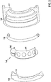
- a preferred electrical contact component 100 accordingly comprises the following components: an outer profile ring 110, a spring ring 150, seven to fifteen balls 142, and a multi-part cage 141 for receiving the balls 142.
- the outer profile ring 110 is designed in such a way that the balls 142 have at least one electrical point contact (preferably several point contacts) with the profile ring 110.
- the inner contour 111 of the profile ring 110 can have different shapes (prism, rectangular, trapezoidal, round, semicircular, etc.).
- a wiring tape (supply of energy / current) can be welded to the outside of the profile ring 110.
- the profile ring 110 is preferably a classic turned part, but can also be produced by MIM (metal injection molding) or other shaping methods such as printing or pressing and sintering.
- the profile ring 110 can be formed in one piece but also in two pieces 120, 130.
- a two-part profile ring 110 is used, after the balls 142 and the cage 141 have been assembled, the two parts 120, 130 are joined to one another in a materially bonded manner, for example by pressing, welding, gluing, soldering, riveting or spots.
- the spring ring 150 consists of a one-piece resilient component which, on the one hand, ensures constant contact between ball 142 and profile ring 110 and, on the other hand, allows the balls 142 to spring in the radial direction (inward and outward).
- the spring ring 150 can be designed to be open or closed. Cross-sectional shapes of the spring ring 150 can assume the following geometries: o / c / s / z shape.
- the spring ring 150 can also be a closed spiral spring.
- the balls 142 are dimensioned in such a way that when the electrode 300 is plugged in, electrical contact is made between the electrode 300 and the profile ring 110 (via the spring ring 150).
- a cage 141 is used to hold the balls 142 in the profile ring 110.
- the cage 141 has the task of keeping the balls 142 at a distance and position from one another.
- the cage 141 can be resilient in at least the radial direction in the event that the spring ring 150 can be omitted as a component.
- the cage 141 can be implemented as a closed or as an open ring and consist of one or more parts. Suitable materials for the cage are, for example, plastic (e.g. polyamide), nitinol, 1.4435, platinum iridium, MP35N, titanium, stainless steel and all other types of material that meet the requirements for electrical contact in the permanent implant.
- the outer ring is preferably made of a platinum iridium alloy and the balls of the ball bearing are made of MP35N, 1.4435 (stainless steel) or titanium.
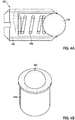
- each contact body 142 which is preferably designed as a ball, with the spring element 150 being arranged within a sleeve 144, which together with the sleeve 144 forms a resilient pressure piece 143 ( Figures 4a and 4b ).
- the spring element 150 is preferably designed as a helical spring.
- the resilient pressure piece 143 in particular the sleeve 144 and the spring element in the groove 111 of the outer profile ring 120 consisting of housing 120 and cover 130, arranged or fastened.
- a cage element 141 is used for spacing and positioning the contact bodies 141 and thus also the spring elements 150 ( Figures 4c and 4d ).
- Electrical contact component 100 Outer ring / profile ring 110 Groove outer ring / profile ring 111 Housing outer ring / profile ring 120 Bridge housing 121 Cover outer ring / profile ring 130 Bridge cover 131 Electrical contact element 140 Cage element 141 Contact body (ball) 142 Resilient pressure piece 143 Thrust piece sleeve 144 Spring element 150 Contact socket 200 Plug / electrode lead 300
Landscapes
- Health & Medical Sciences (AREA)
- Engineering & Computer Science (AREA)
- Biomedical Technology (AREA)
- Nuclear Medicine, Radiotherapy & Molecular Imaging (AREA)
- Radiology & Medical Imaging (AREA)
- Life Sciences & Earth Sciences (AREA)
- Animal Behavior & Ethology (AREA)
- General Health & Medical Sciences (AREA)
- Public Health (AREA)
- Veterinary Medicine (AREA)
- Electrotherapy Devices (AREA)
Priority Applications (1)
| Application Number | Priority Date | Filing Date | Title |
|---|---|---|---|
| US16/839,246 US11116987B2 (en) | 2019-04-17 | 2020-04-03 | Electrical contact component |
Applications Claiming Priority (1)
| Application Number | Priority Date | Filing Date | Title |
|---|---|---|---|
| EP19169882 | 2019-04-17 |
Publications (2)
| Publication Number | Publication Date |
|---|---|
| EP3725366A1 true EP3725366A1 (fr) | 2020-10-21 |
| EP3725366B1 EP3725366B1 (fr) | 2021-12-15 |
Family
ID=66217966
Family Applications (1)
| Application Number | Title | Priority Date | Filing Date |
|---|---|---|---|
| EP19180525.8A Active EP3725366B1 (fr) | 2019-04-17 | 2019-06-17 | Composant de contact électrique |
Country Status (2)
| Country | Link |
|---|---|
| US (1) | US11116987B2 (fr) |
| EP (1) | EP3725366B1 (fr) |
Families Citing this family (17)
| Publication number | Priority date | Publication date | Assignee | Title |
|---|---|---|---|---|
| US11241297B2 (en) | 2016-12-12 | 2022-02-08 | Cadwell Laboratories, Inc. | System and method for high density electrode management |
| US11517239B2 (en) | 2018-04-05 | 2022-12-06 | Cadwell Laboratories, Inc. | Systems and methods for processing and displaying electromyographic signals |
| US11596337B2 (en) | 2018-04-24 | 2023-03-07 | Cadwell Laboratories, Inc | Methods and systems for operating an intraoperative neurophysiological monitoring system in conjunction with electrocautery procedures |
| US11185684B2 (en) | 2018-09-18 | 2021-11-30 | Cadwell Laboratories, Inc. | Minimally invasive two-dimensional grid electrode |
| US11517245B2 (en) | 2018-10-30 | 2022-12-06 | Cadwell Laboratories, Inc. | Method and system for data synchronization |
| US11471087B2 (en) | 2018-11-09 | 2022-10-18 | Cadwell Laboratories, Inc. | Integrity verification system for testing high channel count neuromonitoring recording equipment |
| US12533069B2 (en) | 2018-11-09 | 2026-01-27 | Cadwell Laboratories, Inc. | Systems and methods of electrode switching for neurophysiological sensing and stimulation |
| US11317841B2 (en) | 2018-11-14 | 2022-05-03 | Cadwell Laboratories, Inc. | Method and system for electrode verification |
| US11529107B2 (en) | 2018-11-27 | 2022-12-20 | Cadwell Laboratories, Inc. | Methods for automatic generation of EEG montages |
| US11128076B2 (en) | 2019-01-21 | 2021-09-21 | Cadwell Laboratories, Inc. | Connector receptacle |
| EP3725366B1 (fr) * | 2019-04-17 | 2021-12-15 | BIOTRONIK SE & Co. KG | Composant de contact électrique |
| CN113612047B (zh) * | 2020-10-28 | 2024-05-24 | 湖南华峰新宇电子有限公司 | 一种防卡死复位迅速的信号连接器插座 |
| DE102021102864B3 (de) * | 2021-02-08 | 2022-01-20 | Heraeus Deutschland GmbH & Co. KG | Federkontaktring |
| CN113113791A (zh) * | 2021-04-09 | 2021-07-13 | 广东电网有限责任公司 | 一种端子排插拔式接线系统 |
| US12514549B2 (en) | 2021-08-31 | 2026-01-06 | Cadwell Laboratories, Inc. | Methods and systems for evaluating echo data contemporaneous with an electrodiagnostic study |
| DE102021210211A1 (de) * | 2021-09-15 | 2023-03-16 | Zf Friedrichshafen Ag | Kontaktierungsring zum elektrischen Potenzialausgleich an rotierenden Wellen |
| WO2024050326A1 (fr) * | 2022-08-31 | 2024-03-07 | Tc1 Llc | Connecteur à ressort circulaire à extrémité en boucle pour dispositif médical implantable |
Citations (4)
| Publication number | Priority date | Publication date | Assignee | Title |
|---|---|---|---|---|
| US6498952B2 (en) * | 2001-03-08 | 2002-12-24 | Pacesetter, Inc. | Hermetically sealed feedthrough connector using shape memory alloy for implantable medical device |
| US20130197603A1 (en) * | 2012-01-27 | 2013-08-01 | Greatbatch, Ltd. | Contact block using spherical electrical contacts for electrically contacting implantable leads |
| US20160164195A1 (en) * | 2014-12-04 | 2016-06-09 | Biotronik Se & Co. Kg | Contact element and method for producing a contact element |
| DE102016217673A1 (de) * | 2016-09-15 | 2018-03-15 | Te Connectivity Germany Gmbh | Elektrischer Kontakt für einen Steckverbinder, mit drehbaren Wälzkontaktkörpern und elektrische Steckverbindung mit einem solchen Kontakt |
Family Cites Families (17)
| Publication number | Priority date | Publication date | Assignee | Title |
|---|---|---|---|---|
| US1450172A (en) * | 1920-03-08 | 1923-04-03 | Edward Dewald Jr | Swivel-plug connector |
| US2328212A (en) * | 1942-02-13 | 1943-08-31 | Harry Cleason | Electric swivel |
| US3387250A (en) * | 1966-03-08 | 1968-06-04 | Bjorn James | Electric swivel connection |
| FR2100554A1 (fr) * | 1970-06-22 | 1972-03-24 | Falbet Jean | |
| FR2180550B1 (fr) * | 1972-04-20 | 1978-02-10 | Doloise Metallurgique | |
| US3832674A (en) * | 1972-12-11 | 1974-08-27 | Mark Products | Electrical connector |
| US4157857A (en) * | 1977-07-18 | 1979-06-12 | Western Electric Company, Inc. | Edge connector for printed circuit boards |
| US4469104A (en) * | 1982-07-16 | 1984-09-04 | Cordis Corporation | Multipolar connector for pacing lead |
| EP0269430A3 (fr) * | 1986-11-26 | 1989-02-22 | A. F. BULGIN & COMPANY PLC. | Connecteur électrique |
| US5281148A (en) * | 1992-09-15 | 1994-01-25 | Trakker, Inc. | Electrical circuit card connector |
| US5321583A (en) * | 1992-12-02 | 1994-06-14 | Intel Corporation | Electrically conductive interposer and array package concept for interconnecting to a circuit board |
| US6162062A (en) * | 1999-01-05 | 2000-12-19 | Liao; Sheng Hsin | Structure of telephone connector |
| DE10227156A1 (de) * | 2002-06-18 | 2004-01-08 | Harting Electro-Optics Gmbh & Co. Kg | Steckverbinder mit verschiebbarer Steckerteil-Aufnahme |
| WO2013155121A1 (fr) * | 2012-04-09 | 2013-10-17 | Cbg Corporation | Connecteur électrique radial résistant aux fluides |
| DE102016217667B4 (de) * | 2016-09-15 | 2020-04-02 | Te Connectivity Germany Gmbh | Elektrischer Kontakt mit Wälzkontaktkörpern an sich gegenüberliegenden Seiten sowie Steckverbindung mit einem solchen Kontakt |
| US20190393648A9 (en) * | 2016-12-27 | 2019-12-26 | St. Jude Medical, Cardiology Division, Inc. | Devices for detangling and inhibiting cable entanglement during manipulation of catheters |
| EP3725366B1 (fr) * | 2019-04-17 | 2021-12-15 | BIOTRONIK SE & Co. KG | Composant de contact électrique |
-
2019
- 2019-06-17 EP EP19180525.8A patent/EP3725366B1/fr active Active
-
2020
- 2020-04-03 US US16/839,246 patent/US11116987B2/en not_active Expired - Fee Related
Patent Citations (4)
| Publication number | Priority date | Publication date | Assignee | Title |
|---|---|---|---|---|
| US6498952B2 (en) * | 2001-03-08 | 2002-12-24 | Pacesetter, Inc. | Hermetically sealed feedthrough connector using shape memory alloy for implantable medical device |
| US20130197603A1 (en) * | 2012-01-27 | 2013-08-01 | Greatbatch, Ltd. | Contact block using spherical electrical contacts for electrically contacting implantable leads |
| US20160164195A1 (en) * | 2014-12-04 | 2016-06-09 | Biotronik Se & Co. Kg | Contact element and method for producing a contact element |
| DE102016217673A1 (de) * | 2016-09-15 | 2018-03-15 | Te Connectivity Germany Gmbh | Elektrischer Kontakt für einen Steckverbinder, mit drehbaren Wälzkontaktkörpern und elektrische Steckverbindung mit einem solchen Kontakt |
Also Published As
| Publication number | Publication date |
|---|---|
| US20200330772A1 (en) | 2020-10-22 |
| US11116987B2 (en) | 2021-09-14 |
| EP3725366B1 (fr) | 2021-12-15 |
Similar Documents
| Publication | Publication Date | Title |
|---|---|---|
| EP3725366B1 (fr) | Composant de contact électrique | |
| EP2823856B1 (fr) | Composant de contact à ressort, douille de prise et composant de prise de contact | |
| DE69027846T2 (de) | Verbindungsanordnung zur zufuhr bei implantierbarer ärztlichen vorrichtung | |
| EP2711046B1 (fr) | Ligne d'électrodes et élément de raccordement pour implants électromédicaux | |
| DE102008021064A1 (de) | Anschlussgehäuse für ein elektromedizinisches Implantat | |
| EP1897588A1 (fr) | Conducteurs tranversants | |
| DE102018221355B4 (de) | Kontaktierungsverfahren und System | |
| DE102018124307A1 (de) | Stecker mit einem umspritzten, nicht drehbaren Steckeranschluss und vier Anschlüssen, insbesondere IS4-/DF4-Stecker | |
| EP2740516A2 (fr) | Procédé de fabrication d'un module d'alésage de prise multipôles et module d'alésage de prise ainsi fabriqué | |
| DE3912189A1 (de) | Schutzleiterverbindung | |
| EP1955729B1 (fr) | Ligne d'électrodes et élément de raccord pour un stimulateur cardiaque implantable | |
| DE102018221635B3 (de) | Kontaktierungsverfahren und System | |
| DE202007018766U1 (de) | Kontaktmodul für ein medizinisches Implantat | |
| DE102018105770A1 (de) | Steckverbinder mit einer Verbindungsanordnung für einen Schutzleiterkontakt | |
| DE69718646T2 (de) | Elektrische anschluss-buchse, insbesondere für einen implantierbaren herzschrittmacher | |
| EP3332836B1 (fr) | Traversée d'un appareil médical électronique implantable | |
| DE102006037122B3 (de) | Medizinische Elektrode mit wenigstens zwei Polen und einem Stecker und deren Verwendung | |
| EP3069760B1 (fr) | Dispositif electromedical implantable | |
| EP3181194A1 (fr) | Réalisation d'un appareil médical électronique, son procédé de production et appareil médical électronique | |
| DE69725341T2 (de) | Kontaktelemente einer vielpoligen steckverbindung an einem elektrodenkabel für eine implantierbare medizinische vorrichtung | |
| DE10339958B4 (de) | Elektrischer Steckkontakt | |
| DE3942735A1 (de) | Aufnehmerspule fuer ein reizstromgeraet zur heilung von knochenschaeden | |
| EP3384958A1 (fr) | Traversée pour éléments d'implants | |
| DE202023106276U1 (de) | Kontaktbuchse für ein implantierbares medizinisches Gerät | |
| DE1036971B (de) | Elektrische Steckbuchse |
Legal Events
| Date | Code | Title | Description |
|---|---|---|---|
| PUAI | Public reference made under article 153(3) epc to a published international application that has entered the european phase |
Free format text: ORIGINAL CODE: 0009012 |
|
| STAA | Information on the status of an ep patent application or granted ep patent |
Free format text: STATUS: THE APPLICATION HAS BEEN PUBLISHED |
|
| AK | Designated contracting states |
Kind code of ref document: A1 Designated state(s): AL AT BE BG CH CY CZ DE DK EE ES FI FR GB GR HR HU IE IS IT LI LT LU LV MC MK MT NL NO PL PT RO RS SE SI SK SM TR |
|
| AX | Request for extension of the european patent |
Extension state: BA ME |
|
| STAA | Information on the status of an ep patent application or granted ep patent |
Free format text: STATUS: REQUEST FOR EXAMINATION WAS MADE |
|
| 17P | Request for examination filed |
Effective date: 20210421 |
|
| RBV | Designated contracting states (corrected) |
Designated state(s): AL AT BE BG CH CY CZ DE DK EE ES FI FR GB GR HR HU IE IS IT LI LT LU LV MC MK MT NL NO PL PT RO RS SE SI SK SM TR |
|
| GRAP | Despatch of communication of intention to grant a patent |
Free format text: ORIGINAL CODE: EPIDOSNIGR1 |
|
| STAA | Information on the status of an ep patent application or granted ep patent |
Free format text: STATUS: GRANT OF PATENT IS INTENDED |
|
| RIC1 | Information provided on ipc code assigned before grant |
Ipc: A61N 1/375 20060101AFI20210623BHEP Ipc: H01R 4/50 20060101ALI20210623BHEP Ipc: H01R 13/24 20060101ALN20210623BHEP Ipc: H01R 24/58 20110101ALN20210623BHEP Ipc: H01R 39/64 20060101ALN20210623BHEP |
|
| INTG | Intention to grant announced |
Effective date: 20210715 |
|
| GRAS | Grant fee paid |
Free format text: ORIGINAL CODE: EPIDOSNIGR3 |
|
| GRAA | (expected) grant |
Free format text: ORIGINAL CODE: 0009210 |
|
| STAA | Information on the status of an ep patent application or granted ep patent |
Free format text: STATUS: THE PATENT HAS BEEN GRANTED |
|
| AK | Designated contracting states |
Kind code of ref document: B1 Designated state(s): AL AT BE BG CH CY CZ DE DK EE ES FI FR GB GR HR HU IE IS IT LI LT LU LV MC MK MT NL NO PL PT RO RS SE SI SK SM TR |
|
| REG | Reference to a national code |
Ref country code: GB Ref legal event code: FG4D Free format text: NOT ENGLISH Ref country code: CH Ref legal event code: EP |
|
| REG | Reference to a national code |
Ref country code: DE Ref legal event code: R096 Ref document number: 502019002987 Country of ref document: DE |
|
| REG | Reference to a national code |
Ref country code: IE Ref legal event code: FG4D Free format text: LANGUAGE OF EP DOCUMENT: GERMAN |
|
| REG | Reference to a national code |
Ref country code: AT Ref legal event code: REF Ref document number: 1455022 Country of ref document: AT Kind code of ref document: T Effective date: 20220115 |
|
| REG | Reference to a national code |
Ref country code: LT Ref legal event code: MG9D |
|
| REG | Reference to a national code |
Ref country code: NL Ref legal event code: MP Effective date: 20211215 |
|
| PG25 | Lapsed in a contracting state [announced via postgrant information from national office to epo] |
Ref country code: RS Free format text: LAPSE BECAUSE OF FAILURE TO SUBMIT A TRANSLATION OF THE DESCRIPTION OR TO PAY THE FEE WITHIN THE PRESCRIBED TIME-LIMIT Effective date: 20211215 Ref country code: LT Free format text: LAPSE BECAUSE OF FAILURE TO SUBMIT A TRANSLATION OF THE DESCRIPTION OR TO PAY THE FEE WITHIN THE PRESCRIBED TIME-LIMIT Effective date: 20211215 Ref country code: FI Free format text: LAPSE BECAUSE OF FAILURE TO SUBMIT A TRANSLATION OF THE DESCRIPTION OR TO PAY THE FEE WITHIN THE PRESCRIBED TIME-LIMIT Effective date: 20211215 Ref country code: BG Free format text: LAPSE BECAUSE OF FAILURE TO SUBMIT A TRANSLATION OF THE DESCRIPTION OR TO PAY THE FEE WITHIN THE PRESCRIBED TIME-LIMIT Effective date: 20220315 |
|
| PG25 | Lapsed in a contracting state [announced via postgrant information from national office to epo] |
Ref country code: SE Free format text: LAPSE BECAUSE OF FAILURE TO SUBMIT A TRANSLATION OF THE DESCRIPTION OR TO PAY THE FEE WITHIN THE PRESCRIBED TIME-LIMIT Effective date: 20211215 Ref country code: NO Free format text: LAPSE BECAUSE OF FAILURE TO SUBMIT A TRANSLATION OF THE DESCRIPTION OR TO PAY THE FEE WITHIN THE PRESCRIBED TIME-LIMIT Effective date: 20220315 Ref country code: LV Free format text: LAPSE BECAUSE OF FAILURE TO SUBMIT A TRANSLATION OF THE DESCRIPTION OR TO PAY THE FEE WITHIN THE PRESCRIBED TIME-LIMIT Effective date: 20211215 Ref country code: HR Free format text: LAPSE BECAUSE OF FAILURE TO SUBMIT A TRANSLATION OF THE DESCRIPTION OR TO PAY THE FEE WITHIN THE PRESCRIBED TIME-LIMIT Effective date: 20211215 Ref country code: GR Free format text: LAPSE BECAUSE OF FAILURE TO SUBMIT A TRANSLATION OF THE DESCRIPTION OR TO PAY THE FEE WITHIN THE PRESCRIBED TIME-LIMIT Effective date: 20220316 |
|
| PG25 | Lapsed in a contracting state [announced via postgrant information from national office to epo] |
Ref country code: NL Free format text: LAPSE BECAUSE OF FAILURE TO SUBMIT A TRANSLATION OF THE DESCRIPTION OR TO PAY THE FEE WITHIN THE PRESCRIBED TIME-LIMIT Effective date: 20211215 |
|
| PG25 | Lapsed in a contracting state [announced via postgrant information from national office to epo] |
Ref country code: SM Free format text: LAPSE BECAUSE OF FAILURE TO SUBMIT A TRANSLATION OF THE DESCRIPTION OR TO PAY THE FEE WITHIN THE PRESCRIBED TIME-LIMIT Effective date: 20211215 Ref country code: SK Free format text: LAPSE BECAUSE OF FAILURE TO SUBMIT A TRANSLATION OF THE DESCRIPTION OR TO PAY THE FEE WITHIN THE PRESCRIBED TIME-LIMIT Effective date: 20211215 Ref country code: RO Free format text: LAPSE BECAUSE OF FAILURE TO SUBMIT A TRANSLATION OF THE DESCRIPTION OR TO PAY THE FEE WITHIN THE PRESCRIBED TIME-LIMIT Effective date: 20211215 Ref country code: PT Free format text: LAPSE BECAUSE OF FAILURE TO SUBMIT A TRANSLATION OF THE DESCRIPTION OR TO PAY THE FEE WITHIN THE PRESCRIBED TIME-LIMIT Effective date: 20220418 Ref country code: ES Free format text: LAPSE BECAUSE OF FAILURE TO SUBMIT A TRANSLATION OF THE DESCRIPTION OR TO PAY THE FEE WITHIN THE PRESCRIBED TIME-LIMIT Effective date: 20211215 Ref country code: EE Free format text: LAPSE BECAUSE OF FAILURE TO SUBMIT A TRANSLATION OF THE DESCRIPTION OR TO PAY THE FEE WITHIN THE PRESCRIBED TIME-LIMIT Effective date: 20211215 Ref country code: CZ Free format text: LAPSE BECAUSE OF FAILURE TO SUBMIT A TRANSLATION OF THE DESCRIPTION OR TO PAY THE FEE WITHIN THE PRESCRIBED TIME-LIMIT Effective date: 20211215 |
|
| PG25 | Lapsed in a contracting state [announced via postgrant information from national office to epo] |
Ref country code: PL Free format text: LAPSE BECAUSE OF FAILURE TO SUBMIT A TRANSLATION OF THE DESCRIPTION OR TO PAY THE FEE WITHIN THE PRESCRIBED TIME-LIMIT Effective date: 20211215 |
|
| REG | Reference to a national code |
Ref country code: DE Ref legal event code: R097 Ref document number: 502019002987 Country of ref document: DE |
|
| PG25 | Lapsed in a contracting state [announced via postgrant information from national office to epo] |
Ref country code: IS Free format text: LAPSE BECAUSE OF FAILURE TO SUBMIT A TRANSLATION OF THE DESCRIPTION OR TO PAY THE FEE WITHIN THE PRESCRIBED TIME-LIMIT Effective date: 20220415 |
|
| PLBE | No opposition filed within time limit |
Free format text: ORIGINAL CODE: 0009261 |
|
| STAA | Information on the status of an ep patent application or granted ep patent |
Free format text: STATUS: NO OPPOSITION FILED WITHIN TIME LIMIT |
|
| PG25 | Lapsed in a contracting state [announced via postgrant information from national office to epo] |
Ref country code: DK Free format text: LAPSE BECAUSE OF FAILURE TO SUBMIT A TRANSLATION OF THE DESCRIPTION OR TO PAY THE FEE WITHIN THE PRESCRIBED TIME-LIMIT Effective date: 20211215 Ref country code: AL Free format text: LAPSE BECAUSE OF FAILURE TO SUBMIT A TRANSLATION OF THE DESCRIPTION OR TO PAY THE FEE WITHIN THE PRESCRIBED TIME-LIMIT Effective date: 20211215 |
|
| 26N | No opposition filed |
Effective date: 20220916 |
|
| PG25 | Lapsed in a contracting state [announced via postgrant information from national office to epo] |
Ref country code: SI Free format text: LAPSE BECAUSE OF FAILURE TO SUBMIT A TRANSLATION OF THE DESCRIPTION OR TO PAY THE FEE WITHIN THE PRESCRIBED TIME-LIMIT Effective date: 20211215 |
|
| PG25 | Lapsed in a contracting state [announced via postgrant information from national office to epo] |
Ref country code: MC Free format text: LAPSE BECAUSE OF FAILURE TO SUBMIT A TRANSLATION OF THE DESCRIPTION OR TO PAY THE FEE WITHIN THE PRESCRIBED TIME-LIMIT Effective date: 20211215 |
|
| REG | Reference to a national code |
Ref country code: BE Ref legal event code: MM Effective date: 20220630 |
|
| PG25 | Lapsed in a contracting state [announced via postgrant information from national office to epo] |
Ref country code: LU Free format text: LAPSE BECAUSE OF NON-PAYMENT OF DUE FEES Effective date: 20220617 Ref country code: FR Free format text: LAPSE BECAUSE OF NON-PAYMENT OF DUE FEES Effective date: 20220630 |
|
| PG25 | Lapsed in a contracting state [announced via postgrant information from national office to epo] |
Ref country code: IT Free format text: LAPSE BECAUSE OF FAILURE TO SUBMIT A TRANSLATION OF THE DESCRIPTION OR TO PAY THE FEE WITHIN THE PRESCRIBED TIME-LIMIT Effective date: 20211215 Ref country code: BE Free format text: LAPSE BECAUSE OF NON-PAYMENT OF DUE FEES Effective date: 20220630 |
|
| P01 | Opt-out of the competence of the unified patent court (upc) registered |
Effective date: 20230612 |
|
| GBPC | Gb: european patent ceased through non-payment of renewal fee |
Effective date: 20230617 |
|
| PG25 | Lapsed in a contracting state [announced via postgrant information from national office to epo] |
Ref country code: MK Free format text: LAPSE BECAUSE OF FAILURE TO SUBMIT A TRANSLATION OF THE DESCRIPTION OR TO PAY THE FEE WITHIN THE PRESCRIBED TIME-LIMIT Effective date: 20211215 Ref country code: CY Free format text: LAPSE BECAUSE OF FAILURE TO SUBMIT A TRANSLATION OF THE DESCRIPTION OR TO PAY THE FEE WITHIN THE PRESCRIBED TIME-LIMIT Effective date: 20211215 Ref country code: GB Free format text: LAPSE BECAUSE OF NON-PAYMENT OF DUE FEES Effective date: 20230617 |
|
| PG25 | Lapsed in a contracting state [announced via postgrant information from national office to epo] |
Ref country code: HU Free format text: LAPSE BECAUSE OF FAILURE TO SUBMIT A TRANSLATION OF THE DESCRIPTION OR TO PAY THE FEE WITHIN THE PRESCRIBED TIME-LIMIT; INVALID AB INITIO Effective date: 20190617 |
|
| PG25 | Lapsed in a contracting state [announced via postgrant information from national office to epo] |
Ref country code: TR Free format text: LAPSE BECAUSE OF FAILURE TO SUBMIT A TRANSLATION OF THE DESCRIPTION OR TO PAY THE FEE WITHIN THE PRESCRIBED TIME-LIMIT Effective date: 20211215 |
|
| PGFP | Annual fee paid to national office [announced via postgrant information from national office to epo] |
Ref country code: IE Payment date: 20240617 Year of fee payment: 6 |
|
| PGFP | Annual fee paid to national office [announced via postgrant information from national office to epo] |
Ref country code: DE Payment date: 20240617 Year of fee payment: 6 |
|
| PG25 | Lapsed in a contracting state [announced via postgrant information from national office to epo] |
Ref country code: MT Free format text: LAPSE BECAUSE OF FAILURE TO SUBMIT A TRANSLATION OF THE DESCRIPTION OR TO PAY THE FEE WITHIN THE PRESCRIBED TIME-LIMIT Effective date: 20211215 |
|
| PGFP | Annual fee paid to national office [announced via postgrant information from national office to epo] |
Ref country code: CH Payment date: 20240701 Year of fee payment: 6 |
|
| REG | Reference to a national code |
Ref country code: AT Ref legal event code: MM01 Ref document number: 1455022 Country of ref document: AT Kind code of ref document: T Effective date: 20240617 |
|
| PG25 | Lapsed in a contracting state [announced via postgrant information from national office to epo] |
Ref country code: AT Free format text: LAPSE BECAUSE OF NON-PAYMENT OF DUE FEES Effective date: 20240617 |
|
| REG | Reference to a national code |
Ref country code: DE Ref legal event code: R119 Ref document number: 502019002987 Country of ref document: DE |
|
| REG | Reference to a national code |
Ref country code: CH Ref legal event code: H13 Free format text: ST27 STATUS EVENT CODE: U-0-0-H10-H13 (AS PROVIDED BY THE NATIONAL OFFICE) Effective date: 20260127 |
|
| PG25 | Lapsed in a contracting state [announced via postgrant information from national office to epo] |
Ref country code: DE Free format text: LAPSE BECAUSE OF NON-PAYMENT OF DUE FEES Effective date: 20260101 Ref country code: IE Free format text: LAPSE BECAUSE OF NON-PAYMENT OF DUE FEES Effective date: 20250617 |
|
| PGFP | Annual fee paid to national office [announced via postgrant information from national office to epo] |
Ref country code: AT Payment date: 20260410 Year of fee payment: 5 |
|
| PG25 | Lapsed in a contracting state [announced via postgrant information from national office to epo] |
Ref country code: CH Free format text: LAPSE BECAUSE OF NON-PAYMENT OF DUE FEES Effective date: 20250630 |