EP3725632B1 - Fahrwegerzeugungssystem und feldarbeitsfahrzeug - Google Patents
Fahrwegerzeugungssystem und feldarbeitsfahrzeug Download PDFInfo
- Publication number
- EP3725632B1 EP3725632B1 EP18889499.2A EP18889499A EP3725632B1 EP 3725632 B1 EP3725632 B1 EP 3725632B1 EP 18889499 A EP18889499 A EP 18889499A EP 3725632 B1 EP3725632 B1 EP 3725632B1
- Authority
- EP
- European Patent Office
- Prior art keywords
- work
- field
- travel
- path
- travel path
- Prior art date
- Legal status (The legal status is an assumption and is not a legal conclusion. Google has not performed a legal analysis and makes no representation as to the accuracy of the status listed.)
- Active
Links
Images




Classifications
-
- B—PERFORMING OPERATIONS; TRANSPORTING
- B60—VEHICLES IN GENERAL
- B60W—CONJOINT CONTROL OF VEHICLE SUB-UNITS OF DIFFERENT TYPE OR DIFFERENT FUNCTION; CONTROL SYSTEMS SPECIALLY ADAPTED FOR HYBRID VEHICLES; ROAD VEHICLE DRIVE CONTROL SYSTEMS FOR PURPOSES NOT RELATED TO THE CONTROL OF A PARTICULAR SUB-UNIT
- B60W40/00—Estimation or calculation of non-directly measurable driving parameters for road vehicle drive control systems not related to the control of a particular sub unit, e.g. by using mathematical models
- B60W40/02—Estimation or calculation of non-directly measurable driving parameters for road vehicle drive control systems not related to the control of a particular sub unit, e.g. by using mathematical models related to ambient conditions
- B60W40/06—Road conditions
-
- A—HUMAN NECESSITIES
- A01—AGRICULTURE; FORESTRY; ANIMAL HUSBANDRY; HUNTING; TRAPPING; FISHING
- A01B—SOIL WORKING IN AGRICULTURE OR FORESTRY; PARTS, DETAILS, OR ACCESSORIES OF AGRICULTURAL MACHINES OR IMPLEMENTS, IN GENERAL
- A01B69/00—Steering of agricultural machines or implements; Guiding agricultural machines or implements on a desired track
- A01B69/007—Steering or guiding of agricultural vehicles, e.g. steering of the tractor to keep the plough in the furrow
- A01B69/008—Steering or guiding of agricultural vehicles, e.g. steering of the tractor to keep the plough in the furrow automatic
-
- A—HUMAN NECESSITIES
- A01—AGRICULTURE; FORESTRY; ANIMAL HUSBANDRY; HUNTING; TRAPPING; FISHING
- A01B—SOIL WORKING IN AGRICULTURE OR FORESTRY; PARTS, DETAILS, OR ACCESSORIES OF AGRICULTURAL MACHINES OR IMPLEMENTS, IN GENERAL
- A01B76/00—Parts, details or accessories of agricultural machines or implements, not provided for in groups A01B51/00 - A01B75/00
-
- A—HUMAN NECESSITIES
- A01—AGRICULTURE; FORESTRY; ANIMAL HUSBANDRY; HUNTING; TRAPPING; FISHING
- A01D—HARVESTING; MOWING
- A01D41/00—Combines, i.e. harvesters or mowers combined with threshing devices
- A01D41/12—Details of combines
- A01D41/127—Control or measuring arrangements specially adapted for combines
- A01D41/1278—Control or measuring arrangements specially adapted for combines for automatic steering
-
- A—HUMAN NECESSITIES
- A01—AGRICULTURE; FORESTRY; ANIMAL HUSBANDRY; HUNTING; TRAPPING; FISHING
- A01D—HARVESTING; MOWING
- A01D75/00—Accessories for harvesters or mowers
-
- B—PERFORMING OPERATIONS; TRANSPORTING
- B60—VEHICLES IN GENERAL
- B60W—CONJOINT CONTROL OF VEHICLE SUB-UNITS OF DIFFERENT TYPE OR DIFFERENT FUNCTION; CONTROL SYSTEMS SPECIALLY ADAPTED FOR HYBRID VEHICLES; ROAD VEHICLE DRIVE CONTROL SYSTEMS FOR PURPOSES NOT RELATED TO THE CONTROL OF A PARTICULAR SUB-UNIT
- B60W30/00—Purposes of road vehicle drive control systems not related to the control of a particular sub-unit, e.g. of systems using conjoint control of vehicle sub-units
- B60W30/02—Control of vehicle driving stability
-
- B—PERFORMING OPERATIONS; TRANSPORTING
- B60—VEHICLES IN GENERAL
- B60W—CONJOINT CONTROL OF VEHICLE SUB-UNITS OF DIFFERENT TYPE OR DIFFERENT FUNCTION; CONTROL SYSTEMS SPECIALLY ADAPTED FOR HYBRID VEHICLES; ROAD VEHICLE DRIVE CONTROL SYSTEMS FOR PURPOSES NOT RELATED TO THE CONTROL OF A PARTICULAR SUB-UNIT
- B60W30/00—Purposes of road vehicle drive control systems not related to the control of a particular sub-unit, e.g. of systems using conjoint control of vehicle sub-units
- B60W30/02—Control of vehicle driving stability
- B60W30/045—Improving turning performance
-
- B—PERFORMING OPERATIONS; TRANSPORTING
- B60—VEHICLES IN GENERAL
- B60W—CONJOINT CONTROL OF VEHICLE SUB-UNITS OF DIFFERENT TYPE OR DIFFERENT FUNCTION; CONTROL SYSTEMS SPECIALLY ADAPTED FOR HYBRID VEHICLES; ROAD VEHICLE DRIVE CONTROL SYSTEMS FOR PURPOSES NOT RELATED TO THE CONTROL OF A PARTICULAR SUB-UNIT
- B60W30/00—Purposes of road vehicle drive control systems not related to the control of a particular sub-unit, e.g. of systems using conjoint control of vehicle sub-units
- B60W30/10—Path keeping
-
- B—PERFORMING OPERATIONS; TRANSPORTING
- B60—VEHICLES IN GENERAL
- B60W—CONJOINT CONTROL OF VEHICLE SUB-UNITS OF DIFFERENT TYPE OR DIFFERENT FUNCTION; CONTROL SYSTEMS SPECIALLY ADAPTED FOR HYBRID VEHICLES; ROAD VEHICLE DRIVE CONTROL SYSTEMS FOR PURPOSES NOT RELATED TO THE CONTROL OF A PARTICULAR SUB-UNIT
- B60W40/00—Estimation or calculation of non-directly measurable driving parameters for road vehicle drive control systems not related to the control of a particular sub unit, e.g. by using mathematical models
- B60W40/02—Estimation or calculation of non-directly measurable driving parameters for road vehicle drive control systems not related to the control of a particular sub unit, e.g. by using mathematical models related to ambient conditions
- B60W40/06—Road conditions
- B60W40/064—Degree of grip
-
- B—PERFORMING OPERATIONS; TRANSPORTING
- B60—VEHICLES IN GENERAL
- B60W—CONJOINT CONTROL OF VEHICLE SUB-UNITS OF DIFFERENT TYPE OR DIFFERENT FUNCTION; CONTROL SYSTEMS SPECIALLY ADAPTED FOR HYBRID VEHICLES; ROAD VEHICLE DRIVE CONTROL SYSTEMS FOR PURPOSES NOT RELATED TO THE CONTROL OF A PARTICULAR SUB-UNIT
- B60W40/00—Estimation or calculation of non-directly measurable driving parameters for road vehicle drive control systems not related to the control of a particular sub unit, e.g. by using mathematical models
- B60W40/10—Estimation or calculation of non-directly measurable driving parameters for road vehicle drive control systems not related to the control of a particular sub unit, e.g. by using mathematical models related to vehicle motion
- B60W40/105—Speed
-
- B—PERFORMING OPERATIONS; TRANSPORTING
- B60—VEHICLES IN GENERAL
- B60W—CONJOINT CONTROL OF VEHICLE SUB-UNITS OF DIFFERENT TYPE OR DIFFERENT FUNCTION; CONTROL SYSTEMS SPECIALLY ADAPTED FOR HYBRID VEHICLES; ROAD VEHICLE DRIVE CONTROL SYSTEMS FOR PURPOSES NOT RELATED TO THE CONTROL OF A PARTICULAR SUB-UNIT
- B60W60/00—Drive control systems specially adapted for autonomous road vehicles
- B60W60/001—Planning or execution of driving tasks
-
- B—PERFORMING OPERATIONS; TRANSPORTING
- B60—VEHICLES IN GENERAL
- B60W—CONJOINT CONTROL OF VEHICLE SUB-UNITS OF DIFFERENT TYPE OR DIFFERENT FUNCTION; CONTROL SYSTEMS SPECIALLY ADAPTED FOR HYBRID VEHICLES; ROAD VEHICLE DRIVE CONTROL SYSTEMS FOR PURPOSES NOT RELATED TO THE CONTROL OF A PARTICULAR SUB-UNIT
- B60W60/00—Drive control systems specially adapted for autonomous road vehicles
- B60W60/001—Planning or execution of driving tasks
- B60W60/0015—Planning or execution of driving tasks specially adapted for safety
- B60W60/0016—Planning or execution of driving tasks specially adapted for safety of the vehicle or its occupants
-
- B—PERFORMING OPERATIONS; TRANSPORTING
- B60—VEHICLES IN GENERAL
- B60W—CONJOINT CONTROL OF VEHICLE SUB-UNITS OF DIFFERENT TYPE OR DIFFERENT FUNCTION; CONTROL SYSTEMS SPECIALLY ADAPTED FOR HYBRID VEHICLES; ROAD VEHICLE DRIVE CONTROL SYSTEMS FOR PURPOSES NOT RELATED TO THE CONTROL OF A PARTICULAR SUB-UNIT
- B60W60/00—Drive control systems specially adapted for autonomous road vehicles
- B60W60/005—Handover processes
-
- B—PERFORMING OPERATIONS; TRANSPORTING
- B60—VEHICLES IN GENERAL
- B60W—CONJOINT CONTROL OF VEHICLE SUB-UNITS OF DIFFERENT TYPE OR DIFFERENT FUNCTION; CONTROL SYSTEMS SPECIALLY ADAPTED FOR HYBRID VEHICLES; ROAD VEHICLE DRIVE CONTROL SYSTEMS FOR PURPOSES NOT RELATED TO THE CONTROL OF A PARTICULAR SUB-UNIT
- B60W60/00—Drive control systems specially adapted for autonomous road vehicles
- B60W60/005—Handover processes
- B60W60/0053—Handover processes from vehicle to occupant
-
- G—PHYSICS
- G05—CONTROLLING; REGULATING
- G05D—SYSTEMS FOR CONTROLLING OR REGULATING NON-ELECTRIC VARIABLES
- G05D1/00—Control of position, course, altitude or attitude of land, water, air or space vehicles, e.g. using automatic pilots
- G05D1/02—Control of position or course in two dimensions
- G05D1/021—Control of position or course in two dimensions specially adapted to land vehicles
- G05D1/0212—Control of position or course in two dimensions specially adapted to land vehicles with means for defining a desired trajectory
- G05D1/0214—Control of position or course in two dimensions specially adapted to land vehicles with means for defining a desired trajectory in accordance with safety or protection criteria, e.g. avoiding hazardous areas
-
- G—PHYSICS
- G05—CONTROLLING; REGULATING
- G05D—SYSTEMS FOR CONTROLLING OR REGULATING NON-ELECTRIC VARIABLES
- G05D1/00—Control of position, course, altitude or attitude of land, water, air or space vehicles, e.g. using automatic pilots
- G05D1/02—Control of position or course in two dimensions
- G05D1/021—Control of position or course in two dimensions specially adapted to land vehicles
- G05D1/0268—Control of position or course in two dimensions specially adapted to land vehicles using internal positioning means
- G05D1/0272—Control of position or course in two dimensions specially adapted to land vehicles using internal positioning means comprising means for registering the travel distance, e.g. revolutions of wheels
-
- G—PHYSICS
- G05—CONTROLLING; REGULATING
- G05D—SYSTEMS FOR CONTROLLING OR REGULATING NON-ELECTRIC VARIABLES
- G05D1/00—Control of position, course, altitude or attitude of land, water, air or space vehicles, e.g. using automatic pilots
- G05D1/60—Intended control result
- G05D1/617—Safety or protection, e.g. defining protection zones around obstacles or avoiding hazards
-
- A—HUMAN NECESSITIES
- A01—AGRICULTURE; FORESTRY; ANIMAL HUSBANDRY; HUNTING; TRAPPING; FISHING
- A01B—SOIL WORKING IN AGRICULTURE OR FORESTRY; PARTS, DETAILS, OR ACCESSORIES OF AGRICULTURAL MACHINES OR IMPLEMENTS, IN GENERAL
- A01B79/00—Methods for working soil
- A01B79/005—Precision agriculture
-
- B—PERFORMING OPERATIONS; TRANSPORTING
- B60—VEHICLES IN GENERAL
- B60W—CONJOINT CONTROL OF VEHICLE SUB-UNITS OF DIFFERENT TYPE OR DIFFERENT FUNCTION; CONTROL SYSTEMS SPECIALLY ADAPTED FOR HYBRID VEHICLES; ROAD VEHICLE DRIVE CONTROL SYSTEMS FOR PURPOSES NOT RELATED TO THE CONTROL OF A PARTICULAR SUB-UNIT
- B60W2300/00—Indexing codes relating to the type of vehicle
- B60W2300/15—Agricultural vehicles
- B60W2300/152—Tractors
-
- B—PERFORMING OPERATIONS; TRANSPORTING
- B60—VEHICLES IN GENERAL
- B60W—CONJOINT CONTROL OF VEHICLE SUB-UNITS OF DIFFERENT TYPE OR DIFFERENT FUNCTION; CONTROL SYSTEMS SPECIALLY ADAPTED FOR HYBRID VEHICLES; ROAD VEHICLE DRIVE CONTROL SYSTEMS FOR PURPOSES NOT RELATED TO THE CONTROL OF A PARTICULAR SUB-UNIT
- B60W2520/00—Input parameters relating to overall vehicle dynamics
- B60W2520/10—Longitudinal speed
-
- B—PERFORMING OPERATIONS; TRANSPORTING
- B60—VEHICLES IN GENERAL
- B60W—CONJOINT CONTROL OF VEHICLE SUB-UNITS OF DIFFERENT TYPE OR DIFFERENT FUNCTION; CONTROL SYSTEMS SPECIALLY ADAPTED FOR HYBRID VEHICLES; ROAD VEHICLE DRIVE CONTROL SYSTEMS FOR PURPOSES NOT RELATED TO THE CONTROL OF A PARTICULAR SUB-UNIT
- B60W2520/00—Input parameters relating to overall vehicle dynamics
- B60W2520/20—Sideslip angle
-
- B—PERFORMING OPERATIONS; TRANSPORTING
- B60—VEHICLES IN GENERAL
- B60W—CONJOINT CONTROL OF VEHICLE SUB-UNITS OF DIFFERENT TYPE OR DIFFERENT FUNCTION; CONTROL SYSTEMS SPECIALLY ADAPTED FOR HYBRID VEHICLES; ROAD VEHICLE DRIVE CONTROL SYSTEMS FOR PURPOSES NOT RELATED TO THE CONTROL OF A PARTICULAR SUB-UNIT
- B60W2520/00—Input parameters relating to overall vehicle dynamics
- B60W2520/26—Wheel slip
-
- B—PERFORMING OPERATIONS; TRANSPORTING
- B60—VEHICLES IN GENERAL
- B60W—CONJOINT CONTROL OF VEHICLE SUB-UNITS OF DIFFERENT TYPE OR DIFFERENT FUNCTION; CONTROL SYSTEMS SPECIALLY ADAPTED FOR HYBRID VEHICLES; ROAD VEHICLE DRIVE CONTROL SYSTEMS FOR PURPOSES NOT RELATED TO THE CONTROL OF A PARTICULAR SUB-UNIT
- B60W2552/00—Input parameters relating to infrastructure
-
- B—PERFORMING OPERATIONS; TRANSPORTING
- B60—VEHICLES IN GENERAL
- B60W—CONJOINT CONTROL OF VEHICLE SUB-UNITS OF DIFFERENT TYPE OR DIFFERENT FUNCTION; CONTROL SYSTEMS SPECIALLY ADAPTED FOR HYBRID VEHICLES; ROAD VEHICLE DRIVE CONTROL SYSTEMS FOR PURPOSES NOT RELATED TO THE CONTROL OF A PARTICULAR SUB-UNIT
- B60W2556/00—Input parameters relating to data
- B60W2556/45—External transmission of data to or from the vehicle
- B60W2556/50—External transmission of data to or from the vehicle of positioning data, e.g. GPS [Global Positioning System] data
-
- B—PERFORMING OPERATIONS; TRANSPORTING
- B60—VEHICLES IN GENERAL
- B60W—CONJOINT CONTROL OF VEHICLE SUB-UNITS OF DIFFERENT TYPE OR DIFFERENT FUNCTION; CONTROL SYSTEMS SPECIALLY ADAPTED FOR HYBRID VEHICLES; ROAD VEHICLE DRIVE CONTROL SYSTEMS FOR PURPOSES NOT RELATED TO THE CONTROL OF A PARTICULAR SUB-UNIT
- B60W2720/00—Output or target parameters relating to overall vehicle dynamics
- B60W2720/12—Lateral speed
-
- B—PERFORMING OPERATIONS; TRANSPORTING
- B60—VEHICLES IN GENERAL
- B60Y—INDEXING SCHEME RELATING TO ASPECTS CROSS-CUTTING VEHICLE TECHNOLOGY
- B60Y2200/00—Type of vehicle
- B60Y2200/20—Off-Road Vehicles
- B60Y2200/22—Agricultural vehicles
- B60Y2200/221—Tractors
Definitions
- the present invention relates to a travel path generation system, and a field work vehicle.
- travel path generation systems that generate a travel path for performing automatic travel in a field in work is performed by which different types of field work vehicles, and field work vehicles that employ such a travel path generation system.
- various field work vehicles such as a tractor equipped with a cultivating apparatus, a tractor equipped with a ploughing apparatus, a rice transplanter, a seeding machine, a fertilizer applicator, and a harvester (combine harvester), are used in accordance with seasons in agricultural work.
- the results of agricultural work performed by these field work vehicles should be information useful for subsequent field work vehicles that are to perform agricultural work later.
- individual ability of agricultural workers has been relied on to use such information, and the results of work performed by the preceding field work vehicles are hardly used by the subsequent field work vehicles using information technologies.
- a combine harvester, a tractor, and a rice transplanter are provided with a GPS communicating portion and a control device, and a shared recording device is prepared.
- the recording device is attached to the tractor during ploughing work, attached to the rice transplanter during planting work, and is attached to the combine harvester during harvest work.
- the traveling speed of the combine harvester during harvest work and information from the GPS communicating portion are recorded in the recording device, and the amount of fertilizer applied during planting work performed by the seedling planting machine is changed based on the information. For example, the traveling speed of the combine harvester decreases at a position where crops are overgrown, and thus, the amount of fertilizer applied is reduced at this position.
- the ploughing depth is reduced at a position where crops are overgrown such that the fertilizer does not deposit at this position.
- a field management system in Patent Document 2 data on field work performed by a tractor, a rice transplanter, and a harvester is integrally stored and managed in a layer structure for the purpose of efficient agricultural business management in a field.
- field outer-shape data is generated based on a travel trajectory that is obtained by the tractor traveling to circulate around the outer periphery of the field, and the generated data is stored.
- a crop planting position that is generated by the rice transplanter (seeding machine) traveling for work is stored in association with coordinate positions in a field.
- a yield per unit of travel that is generated in association with the travel position when the harvester travels for harvesting work is associated with a coordinate position in a field, and is stored as a yield per minute parcel in the field.
- an object of the present invention is to provide a travel path calculation technology with which, when a travel path for automatic travel is set, consideration is given to a work state of a field work vehicle that has previously carried out work.
- a travel path generation system is a travel path generation system that generates a travel path for performing automatic travel in a field in which work is performed by different types of field work vehicles, and the system includes: a work information acquisition portion for acquiring work information regarding a preceding field work vehicle that has performed work previously in the field; and a path calculation portion for calculating, based on the work information from the work information acquisition portion, the travel path for a subsequent field work vehicle that is to perform automatic travel work hereafter in the field in which work has been performed by the preceding field work vehicle.
- the preceding field work vehicle is a seedling row forming machine that forms seedling rows, such as a seeding machine or a rice transplanter
- the work information regarding the seedling row forming machine includes planted seedling row information indicating a seedling row formation map
- the subsequent field work vehicle is a harvester that has a harvesting portion in a machine-body front portion and harvests crops in the field while automatically traveling.
- the travel path for the harvester is calculated based on the planted seedling row information by the path calculation portion such that a path extending in a direction in which the seedling rows extend is elongated.
- Calculation of a travel path for a large-scale field and a field with a complex outer shape may not be appropriately performed due to, for example, restrictions of a travel path calculation algorithm.
- a dividing path that divides a field into a plurality of portions is set, and a travel path is separately calculated for divided fields that divided by the dividing path.
- a travel path portion that is perpendicular to the seedling rows and a travel path portion that skews relative to the seedling rows may possibly be elongated in a travel path that is calculated for each of the divided field.
- the path calculation portion includes a dividing path calculation portion for calculating a dividing path that divides the field, as one travel path for the harvester, and the dividing path calculation portion calculates the dividing path based on the planted seedling row information, such that the travel path in divided fields that are divided by the dividing path can be readily extended in the direction in which the seedling rows extend.
- a harvesting portion is provided with a plurality of dividers that sort planted grain culms by seedling row, the plurality of dividers are required to accurately proceed between the seedling rows.
- the harvesting portion is provided with dividers that are arranged laterally, and the travel path is corrected so as to optimize positions of the seedling rows on an unworked area side that are calculated based on the planted seedling row information, and a position of one of the dividers, on an end side in a machine-body left-right direction.
- a divider on an end side in the left-right direction proceeds onto a boundary seedling row in the harvested area that is closest to the unharvested area, or between a boundary seedling row in the harvested area and a boundary seedling row in unworked area, as a result, all of the dividers proceed between the seedling rows, and thus, planted grain culms can be favorably sorted by the dividers.
- a field work vehicle that has large rear wheels, such as a tractor, or has crawler apparatuses travels in a field, large wheel tracks are left in a soft field, and an uneven surface occurs in the field. If a subsequent field work vehicle crosses such an uneven surface, vibration occurs that obstructs precise work travel. In addition, if a ridge is formed by a tractor and a subsequent field work vehicle crosses this ridge, the ridge will be partially destroyed. Accordingly, a travel path is preferable through which a subsequent field work vehicle does not cross an uneven surface or a ridge that is left by a preceding field work vehicle, as much as possible.
- the work information includes ridge information indicating a ridge formation map of ridges formed by a tractor, and the path calculation portion calculates the travel path such that the ridges are less often crossed by the subsequent field work vehicle.
- the work information includes ridge information indicating a ridge formation map of ridges formed by a tractor, and the path calculation portion calculates the travel path such that, when the subsequent field work vehicle turns, a turning inner portion of a traveling apparatus of the subsequent field work vehicle does not ride up the ridges.
- the object of the present invention is not only the travel path generation system but also a field work vehicle that employs this travel path generation system.
- This field work vehicle includes the above-described travel path generation system, and also includes a vehicle position detection module that detects a vehicle position, and an automatic travel control portion that enables automatic travel based on the travel path calculated by the path calculation portion, and the vehicle position.
- the field work vehicle according to the present invention can utilize all of the effects of the travel path generation system, including the above-described preferable embodiments.
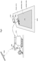
- FIG. 1 shows a tractor, a rice transplanter (which may alternatively be a seeding machine), and a harvester (a normal combine harvester), as field work vehicles that perform work in the same field at different times.
- the rice transplanter and the seeding machine form rows of seedlings, which are planted grain culms, in the field, and are therefore also called seedling row forming machines.
- Work information which includes a travel path map that indicates a travel trajectory of a preceding field work vehicle that has performed work previously in the field, is stored and managed in a work information database or the like.
- a travel path for a subsequent field work vehicle that is about to work hereafter is calculated while giving consideration to the work information regarding the preceding field work vehicle that has performed work previously.
- planted seedling row information which includes a seedling row formation map that indicates seedling rows formed by the seeding machine or the rice transplanter that has performed work previously, is stored as work information and managed in the work information database or the like.
- this seedling row formation map can be used to calculate a travel path for the harvester.
- a path calculation algorithm for calculating a travel path can calculate a travel path for the harvester such that a travel path portion extending in a direction in which seedling rows extend is elongated, while giving consideration to the seedling row formation map.
- the subsequent field work vehicle that is to work hereafter is a harvester such as a combine harvester
- ridge information which includes a ridge formation map that indicates positions of ridges formed by a tractor that has performed work previously, and is stored as work information and managed in the work information database or the like.
- the ridge formation map can be used to calculate a travel path for the harvester.
- the path calculation algorithm can calculate a travel path for the harvester such that the harvester less often crosses the ridges, while giving consideration to the ridge formation map.
- the path calculation algorithm can calculate a travel path for the harvester such that a traveling apparatus (crawler; wheel) on the turning inner side of the harvester does not ride up a ridge.
- the path calculation algorithm can also be provided with a function of calculating the dividing path.
- the dividing path is calculated based on the seedling row formation map that is read out from the work information that is stored and managed, such that travel paths in divided fields divided by the dividing path can be readily extended in the direction in which the seedling rows extend.
- the work information related to work performed by different types of field work vehicles in the same field is stored after divided into a field map layer and work information layers for the respective types, as schematically shown in FIG. 1 .
- the work information layers in which work information regarding the respective types of field work vehicles is stored include travel path maps (all types), a seedling row formation map (rice transplanter or seeding machine), a ridge formation map (tractor), a yield map (harvester), and the like.
- front/forward (a indicated by an arrow F shown in FIG. 2 ) means a forward direction in the machine-body front-rear direction (travel direction)
- rear/rearward (a direction indicated by an arrow B shown in FIG. 2 ) means a rearward direction in the machine-body front-rear direction (travel direction), unless otherwise stated.
- a left-right direction, or a lateral direction means a machine-body transverse direction (machine-body width direction) that is perpendicular to the machine-body front-rear direction.
- “Upper/above” (a direction indicated by an arrow U shown in FIG. 2 ) and “lower/below” (a direction indicated by an arrow D shown in FIG. 2 ) refers to a positional relationship in the vertical direction of a vehicle body, and indicates a relationship in terms of a ground height.
- the combine harvester includes a machine body 210, crawler-type traveling apparatuses 211, an operation section 212, a threshing apparatus 213, a grain tank 214, a harvesting portion H2, a conveyance apparatus 216, a grain discharge apparatus 218, and a satellite positioning module 280.
- the traveling apparatuses 211 are provided below the machine body 210.
- the combine harvester is configured to be automotive with the traveling apparatuses 211.
- the operation section 212, the threshing apparatus 213, and the grain tank 214 are provided above the traveling apparatuses 211 and constitute the upper part of the machine body 210.
- An operator who operates the combine harvester or an observer who monitors work of the combine harvester can board the operation section 212. Note that the observer may monitor the work of the combine harvester from outside the combine harvester.
- the grain discharge apparatus 218 is coupled to a rear lower portion of the grain tank 214.
- the satellite positioning module 280 is attached to the upper front portion of the operation section 212.
- the harvesting portion H2 is provided in a front portion of the machine body 210.
- the conveyance apparatus 216 is provided on the rear side of the harvesting portion H2.
- the harvesting portion H2 has a cutting mechanism 215 and a reel 217.
- the cutting mechanism 215 reaps planted grain culms in the field.
- the reel 217 rakes planted grain culms to be harvested, while being driven to rotate. This configuration enables the combine harvester to travel for work using the traveling apparatuses 211, while harvesting grains (a kind of farm produce) in the field using the harvesting portion H2.
- Reaped grain culms reaped by the cutting mechanism 215 are conveyed to the threshing apparatus 213 by the conveyance apparatus 216.
- the reaped grain culms undergo a threshing process in the threshing apparatus 213.
- the grains (a kind of harvest) obtained through the threshing process are stored in the grain tank 214.
- the grains stored in the grain tank 214 are discharged to the outside of the vehicle by the grain discharge apparatus 218, as needed.
- a communication terminal 204 is disposed in the operation section 212.
- the communication terminal 204 is fixed to the operation section 212.
- the communication terminal 204 may be attachable to and detachable from the operation section 212, or may be located outside the machine body of the combine harvester.
- this combine harvester can automatically travel along a travel path that is set in a field.
- the satellite positioning module 280 receives a GNSS (global navigation satellite system) signal (including a GPS signal) from an artificial satellite GS2, and outputs positioning data for calculating a vehicle position. The vehicle position is calculated based on this positioning data.
- GNSS global navigation satellite system
- an operator/observer manually operates the combine harvester, and travels for harvesting so as to circulate along a boundary line of the field in an outer-peripheral portion within the field, as shown in FIG. 3 .
- An area that has thus become a harvested area is set as an outer-peripheral area SA2.
- An area that is left as an unharvested area inward of the outer-peripheral area SA2 is set as a work target area CA2.
- the observer causes the combine harvester to travel to circulate three to four times in order to secure the width of the outer-peripheral area SA2 widely to some extent.
- the width of the outer-peripheral area SA2 increases by the working width of the combine harvester, every time the combine harvester circulates once.
- the width of the outer-peripheral area SA2 is the width that is equal to three to four times the working width of the combine harvester.
- the outer-peripheral area SA2 is used as a space with which the combine harvester changes its direction when traveling to harvest in the work target area CA2.
- the outer-peripheral area SA2 is also used as a space when the combine harvester moves to a grain discharging area after finishing harvest travel, and as a space for moving when the combine harvester moves to a refueling area, for example.
- a carrier vehicle CV2 shown in FIG. 3 can collect and transport grains discharged from the combine harvester. When grains are discharged, the combine harvester moves to the vicinity of the carrier vehicle CV2 and thereafter discharges the grains to the carrier vehicle CV2, using the grain discharge apparatus 218.
- a travel path in the work target area CA2 is calculated, as shown in FIG. 4
- the calculated travel path is sequentially set as a target travel path, based on a work travel pattern.
- the combine harvester is subjected to automatic travel control so as to travel along the set target travel path.
- FIG. 5 shows a control system of the combine harvester that uses the travel path generation system according to the present invention.
- FIG. 5 shows functional portions provided in a management computer 300, which is installed in a management center that provides a cloud service, and functional portions provided in the control system of the combine harvester.
- the functional portions provided in the management computer 300 can alternatively be provided in the control system of the combine harvester, or in the communication terminal 204 that is brought into the combine harvester.
- the control system of the combine harvester is constituted by a large number of electronic control units that are called ECUs, various operational devices, a sensor group and a switch group, and a wired network such as an in-vehicle LAN for data transmission therebetween.
- a notification device 291 is a device for notifying the operator or the like of a work travel state and various warnings, and may include a buzzer, a lamp, a speaker, a display, or the like.
- the communicating portion 292 is used for the control system of the combine harvester to exchange data with the management computer 300 installed at a remote place and other communication terminals 204.
- the communication terminals 204 include a tablet computer that is operated by an observer who is standing in the field, or an observer (including the operator) who is sitting in the combine harvester.
- the control unit 206 is a core element of this control system, and is illustrated as an aggregate of a plurality of ECUs.
- the positioning data from the satellite positioning module 280 is input to the control unit 206 through the in-vehicle LAN.
- the control unit 206 includes an output processing portion 206B and an input processing portion 206A as input and output interfaces.
- the output processing portion 206B is connected to a traveling device group 207A and a work device group 207B.
- a travel-related detection sensor group 208A, a work-related detection sensor group 208B, and the like, are connected to the input processing portion 206A.
- the travel-related detection sensor group 208A includes sensors for detecting the state of an engine speed adjustment tool, an acceleration pedal, a brake pedal, a gear shift operational tool, and the like.
- the work-related detection sensor group 208B includes sensors for detecting the apparatus state of the harvesting portion H2, the threshing apparatus 213, the conveyance apparatus 216, and the grain discharge apparatus 218, as well as the state of grain culms and grains.
- the control unit 206 includes a work information management module 205, a travel control portion 261, a work control portion 262, a path calculation portion 263, a harvest management portion 264, a vehicle position calculation portion 265, and a notification portion 266.
- the notification portion 266 generates notification data based on a command or the like from the functional portions of the control unit 206, and gives the generated notification data to the notification device 291.
- the vehicle position calculation portion 265 calculates a vehicle position, which is the map coordinates (or field coordinates) of a portion of the machine body 210 that is set in advance, based on the positioning data that is sequentially sent from the satellite positioning module 280.
- the satellite positioning module 280 and the vehicle position detection module 265 constitute a vehicle position detection module for detecting the vehicle position.
- the travel control portion 261 has an engine control function, a steering control function, a vehicle speed control function, and the like, and gives a travel control signal to the traveling device group 207A.
- the work control portion 262 gives a work control signal to the work device group 207B in order to control operations of the harvesting portion H2, the threshing apparatus 213, the grain discharge apparatus 218, the conveyance apparatus 216, and the like.
- the manual travel control portion 2611 If the manual travel mode is selected, the manual travel control portion 2611 generates a control signal based on an operation performed by the operator, and thus controls the traveling device group 207A.
- the travel path setting portion 2613 sets the travel path created by the path calculation portion 263 as a target travel path during automatic travel. Note that this travel path may also be used during manual travel as guidance for the combine harvester to travel along this travel path.
- the automatic travel control portion 2612 If the automatic travel mode is selected, the automatic travel control portion 2612 generates a control signal for automatic steering and a vehicle speed change, and controls the traveling device group 207A.
- a control signal related to automatic steering is generated so as to resolve an orientation shift and a position shift between the target travel path that is set by the travel path setting portion 2613 and the vehicle position calculated by the vehicle position calculation portion 265.
- a control signal related to a vehicle speed change is generated based on a vehicle speed value that is set in advance.
- the work control portion 262 If the manual travel mode is selected, the work control portion 262 generates a control signal to control the work device group 207B, based on an operation performed by the operator. If the automatic travel mode is selected, the work control portion 262 also generates a control signal in accordance with a preset travel position or travel state, and controls the work device group 207B. Needless to say, even in the automatic travel mode, the work control portion 262 can also control the work device group 207B, at least partially based on an operation performed by the operator.
- the combine harvester includes the harvest management portion 264 as a yield measurement function of measuring the yield (harvest amount) per unit of travel, and a functional portion for measuring the taste (here, moisture and protein) of grains harvested per unit of travel.
- the harvest management portion 264 is provided with a harvest map generation portion 2641, and the harvest map generation portion 2641 generates a harvest map while associating the yield per unit of travel and the taste with the travel trajectory (vehicle position) of the machine body 210.
- the work information management module 205 includes a work information generation portion 251, a work information acquisition portion 252, and a work information processing portion 253.
- the work information generation portion 251 generates work information, which is information regarding work that has actually been performed in the field (harvest work in the case of a combine harvester; cultivating work in the case of a tractor; seeding work or seedling planting work in the case of a seeding machine or a rice transplanter, etc.).
- the work information generated by the work information generation portion 251 of the combine harvester includes, as harvest information, a travel trajectory in the field, the yield (yield map) per unit parcel, the taste (quality map), and the like.
- the generated work information is linked with a field ID for specifying the field, a manager ID for specifying a manager who has engaged in the work, a field work vehicle ID for specifying the combine harvester that has performed the work, and the like, and is uploaded to the management computer 300, by the work information processing portion 253.
- work information includes, as planting information, a seedling row formation map that indicates, for example, a travel trajectory in the field, a seedling row direction of seedlings that is obtained based on the travel trajectory, a fertilizer application map, and the like.
- planting information a seedling row formation map that indicates, for example, a travel trajectory in the field, a seedling row direction of seedlings that is obtained based on the travel trajectory, a fertilizer application map, and the like.
- work information includes, as cultivation information, a travel trajectory in the field, a ridge formation map that includes a ridge extending direction that is obtained based on the travel trajectory, and the like.
- the work information acquisition portion 252 downloads, from the management computer 300, work information regarding a preceding field work vehicle that has performed work previously in the field in which field work is to be performed hereafter.
- the management computer 300 includes a communicating portion 301 that exchanges data with the communicating portion 292 of each field work vehicle, a field management portion 302, a work vehicle management portion 303, and a work information storage management portion 304.
- the field management portion 302 manages field information regarding each field in which work is performed by different types of field work vehicles. Field information includes a field owner, a field map, soil characteristics, planting history, and the like.
- the work vehicle management portion 303 manages work vehicle information, which includes an owner of a work vehicle, a type name, work vehicle specifications, travel distance, travel time, and the like.
- the work information storage management portion 304 stores and manages work information that is generated and uploaded by the work information generation portions 251 of not only the combine harvester but also other field work vehicles, in the form in which the work information is linked with corresponding field information and corresponding work vehicle information.
- the work information storage management portion 304 can store and manage work information in a work information layer structure for each field and each field work vehicle, as shown in FIG. 1 .
- the work information storage management portion 304 can send, to a field work vehicle that is to work hereafter, work information regarding a field work vehicle that has performed work previously in the same field.
- the work information acquisition portion 252 downloads, from the management computer 300, planted seedling row information that includes a seedling row formation map included in the work information generated by a rice transplanter that has previously performed seedling planting work in the field.
- the work information processing portion 253 obtains a direction in which seedling rows extend, based on the acquired seedling row formation map, and gives the obtained direction in which seedling rows extend to the path calculation portion 263.
- the path calculation portion 263 calculates a travel path such that a path extending along the direction in which seedling rows extend is as long as possible.
- the path calculation portion 263 in this embodiment includes a dividing path calculation portion 2631 for calculating a dividing path.
- the dividing path calculation portion 2631 calculates a dividing path such that travel paths in divided fields divided by the dividing path can be readily extended in the direction in which seedling rows extend.
Landscapes
- Engineering & Computer Science (AREA)
- Mechanical Engineering (AREA)
- Automation & Control Theory (AREA)
- Transportation (AREA)
- Life Sciences & Earth Sciences (AREA)
- Physics & Mathematics (AREA)
- Environmental Sciences (AREA)
- Human Computer Interaction (AREA)
- Mathematical Physics (AREA)
- Soil Sciences (AREA)
- Aviation & Aerospace Engineering (AREA)
- Radar, Positioning & Navigation (AREA)
- Remote Sensing (AREA)
- General Physics & Mathematics (AREA)
- Guiding Agricultural Machines (AREA)
- Business, Economics & Management (AREA)
- Health & Medical Sciences (AREA)
- Artificial Intelligence (AREA)
- Evolutionary Computation (AREA)
- Game Theory and Decision Science (AREA)
- Medical Informatics (AREA)
- Control Of Position, Course, Altitude, Or Attitude Of Moving Bodies (AREA)
Claims (6)
- Fahrwegerzeugungssystem, das einen Fahrweg zum Durchführen von automatischem Fahren in einem Feld erzeugt, in dem von verschiedenen Arten von Feldarbeitsfahrzeugen Arbeiten durchgeführt werden, das System umfassend:einen Arbeitsinformationserfassungsabschnitt (252) zum Erfassen von Arbeitsinformationen in Bezug auf ein vorhergehendes Feldarbeitsfahrzeug, das zuvor Arbeiten im Feld durchgeführt hat; undeinen Wegberechnungsabschnitt (263) zum Berechnen, basierend auf den Arbeitsinformationen aus dem Arbeitsinformationserfassungsabschnitt (252) des Fahrwegs für ein nachfolgendes Feldarbeitsfahrzeug, das danach automatische Fahrarbeiten in dem Feld durchführen soll, in dem Arbeiten durch das vorhergehende Feldarbeitsfahrzeug durchgeführt wurden,wobei das vorhergehende Feldarbeitsfahrzeug eine Setzlingreihenbildungsmaschine ist, die Setzlingreihen bildet, wie beispielsweise eine Sämaschine oder eine Reisumsetzmaschine, und die Arbeitsinformationen in Bezug auf die Setzlingreihenbildungsmaschine Informationen über gepflanzte Setzlingreihen beinhalten, die eine Setzlingreihenbildungskarte angeben, und das nachfolgende Feldarbeitsfahrzeug eine Erntemaschine ist, die einen Ernteabschnitt (H2) in einem vorderen Maschinenkörperabschnitt aufweist und Nutzpflanzen auf dem Feld erntet, während sie automatisch fährt;dadurch gekennzeichnet, dass:der Ernteabschnitt (H2) mit Teilern (219) versehen ist, die seitlich angeordnet sind, undder Fahrweg korrigiert wird, um Positionen der Setzlingreihen auf einer Seite der unbearbeiteten Fläche, die basierend auf den Informationen über gepflanzte Setzlingreihen berechnet werden, und eine Position von einem der Teiler (219) auf einer Endseite in einer Links-Rechts-Richtung des Maschinenkörpers (10) optimiert werden.
- Fahrwegerzeugungssystem nach Anspruch 1,
wobei der Fahrweg für die Erntemaschine basierend auf den Informationen über gepflanzte Setzlingreihen durch den Wegberechnungsabschnitt (263) berechnet wird, sodass ein Weg, der sich in einer Richtung erstreckt, in der sich die Setzlingreihen erstrecken, verlängert wird. - Fahrwegerzeugungssystem nach Anspruch 2,wobei der Wegberechnungsabschnitt (263) einen Teilungswegberechnungsabschnitt (2631) zum Berechnen eines Teilungswegs, der das Feld unterteilt, als einen Fahrweg für die Erntemaschine beinhaltet, undder Teilungswegberechnungsabschnitt (2631) den Teilungsweg basierend auf den Informationen über gepflanzte Setzlingreihen berechnet, sodass der Fahrweg in unterteilten Feldern, die durch den Teilungsweg geteilt werden, ohne weiteres in der Richtung verlängert werden kann, in der sich die Setzlingreihen erstrecken.
- Fahrwegerzeugungssystem nach einem der Ansprüche 1 bis 3,wobei die Arbeitsinformationen Pflanzhügelinformationen beinhalten, die eine Pflanzhügelbildungskarte von Pflanzhügeln angibt, die durch einen Traktor gebildet werden, undder Wegberechnungsabschnitt (263) den Fahrweg berechnet, sodass die Pflanzhügel von dem nachfolgenden Feldarbeitsfahrzeug weniger oft überquert werden.
- Fahrwegerzeugungssystem nach einem der Ansprüche 1 bis 4,wobei die Arbeitsinformationen Pflanzhügelinformationen beinhalten, die eine Pflanzhügelbildungskarte von Pflanzhügeln angibt, die durch einen Traktor gebildet werden, undder Wegberechnungsabschnitt (263) den Fahrweg berechnet, sodass, wenn das nachfolgende Feldarbeitsfahrzeug wendet, ein innerer Wendeabschnitt einer Fahrvorrichtung (211) des nachfolgenden Feldarbeitsfahrzeugs nicht über die Pflanzhügel fährt.
- Feldarbeitsfahrzeug, umfassend:das Fahrwegerzeugungssystem nach einem der Ansprüche 1 bis 5;ein Fahrzeugpositionserfassungsmodul (80) zum Erfassen einer Fahrzeugposition; undeinen automatischen Fahrsteuerungsabschnitt (512) zum Ermöglichen von automatischem Fahren basierend auf dem Fahrweg, der von dem Wegberechnungsabschnitt (263) berechnet wird, und der Fahrzeugposition.
Applications Claiming Priority (3)
| Application Number | Priority Date | Filing Date | Title |
|---|---|---|---|
| JP2017240638A JP6974155B2 (ja) | 2017-12-15 | 2017-12-15 | スリップ判定システム |
| JP2017240639A JP6956620B2 (ja) | 2017-12-15 | 2017-12-15 | 走行経路生成システム及び圃場作業車 |
| PCT/JP2018/045355 WO2019117094A1 (ja) | 2017-12-15 | 2018-12-10 | スリップ判定システム、走行経路生成システム及び圃場作業車 |
Publications (3)
| Publication Number | Publication Date |
|---|---|
| EP3725632A1 EP3725632A1 (de) | 2020-10-21 |
| EP3725632A4 EP3725632A4 (de) | 2021-10-20 |
| EP3725632B1 true EP3725632B1 (de) | 2025-04-02 |
Family
ID=66819270
Family Applications (1)
| Application Number | Title | Priority Date | Filing Date |
|---|---|---|---|
| EP18889499.2A Active EP3725632B1 (de) | 2017-12-15 | 2018-12-10 | Fahrwegerzeugungssystem und feldarbeitsfahrzeug |
Country Status (5)
| Country | Link |
|---|---|
| US (1) | US11895937B2 (de) |
| EP (1) | EP3725632B1 (de) |
| KR (1) | KR102599328B1 (de) |
| CN (1) | CN111386215B (de) |
| WO (1) | WO2019117094A1 (de) |
Families Citing this family (73)
| Publication number | Priority date | Publication date | Assignee | Title |
|---|---|---|---|---|
| US11589509B2 (en) | 2018-10-26 | 2023-02-28 | Deere & Company | Predictive machine characteristic map generation and control system |
| US11641800B2 (en) | 2020-02-06 | 2023-05-09 | Deere & Company | Agricultural harvesting machine with pre-emergence weed detection and mitigation system |
| US11672203B2 (en) | 2018-10-26 | 2023-06-13 | Deere & Company | Predictive map generation and control |
| US11079725B2 (en) | 2019-04-10 | 2021-08-03 | Deere & Company | Machine control using real-time model |
| US11467605B2 (en) | 2019-04-10 | 2022-10-11 | Deere & Company | Zonal machine control |
| US11957072B2 (en) | 2020-02-06 | 2024-04-16 | Deere & Company | Pre-emergence weed detection and mitigation system |
| US11178818B2 (en) | 2018-10-26 | 2021-11-23 | Deere & Company | Harvesting machine control system with fill level processing based on yield data |
| US11653588B2 (en) | 2018-10-26 | 2023-05-23 | Deere & Company | Yield map generation and control system |
| US12069978B2 (en) | 2018-10-26 | 2024-08-27 | Deere & Company | Predictive environmental characteristic map generation and control system |
| US11240961B2 (en) | 2018-10-26 | 2022-02-08 | Deere & Company | Controlling a harvesting machine based on a geo-spatial representation indicating where the harvesting machine is likely to reach capacity |
| JP7160701B2 (ja) * | 2019-01-23 | 2022-10-25 | 株式会社小松製作所 | 作業機械のシステム及び方法 |
| US11234366B2 (en) | 2019-04-10 | 2022-02-01 | Deere & Company | Image selection for machine control |
| DE102019111315A1 (de) * | 2019-05-02 | 2020-11-05 | Horsch Leeb Application Systems Gmbh | Autonome landwirtschaftliche Arbeitsmaschine und Verfahren zu deren Betrieb |
| JP7280759B2 (ja) * | 2019-06-20 | 2023-05-24 | ヤンマーパワーテクノロジー株式会社 | 散布作業用の自動走行システム |
| KR102225635B1 (ko) * | 2019-07-19 | 2021-03-12 | 세메스 주식회사 | 대상물 이송 시스템 |
| JP7191001B2 (ja) * | 2019-11-29 | 2022-12-16 | 株式会社クボタ | 自動走行システム |
| US12329148B2 (en) | 2020-02-06 | 2025-06-17 | Deere & Company | Predictive weed map and material application machine control |
| US12225846B2 (en) | 2020-02-06 | 2025-02-18 | Deere & Company | Machine control using a predictive map |
| US12035648B2 (en) | 2020-02-06 | 2024-07-16 | Deere & Company | Predictive weed map generation and control system |
| US11477940B2 (en) | 2020-03-26 | 2022-10-25 | Deere & Company | Mobile work machine control based on zone parameter modification |
| US11874669B2 (en) | 2020-10-09 | 2024-01-16 | Deere & Company | Map generation and control system |
| US11711995B2 (en) | 2020-10-09 | 2023-08-01 | Deere & Company | Machine control using a predictive map |
| US11844311B2 (en) | 2020-10-09 | 2023-12-19 | Deere & Company | Machine control using a predictive map |
| US11849672B2 (en) | 2020-10-09 | 2023-12-26 | Deere & Company | Machine control using a predictive map |
| US11895948B2 (en) | 2020-10-09 | 2024-02-13 | Deere & Company | Predictive map generation and control based on soil properties |
| US11675354B2 (en) | 2020-10-09 | 2023-06-13 | Deere & Company | Machine control using a predictive map |
| US11845449B2 (en) | 2020-10-09 | 2023-12-19 | Deere & Company | Map generation and control system |
| US12386354B2 (en) | 2020-10-09 | 2025-08-12 | Deere & Company | Predictive power map generation and control system |
| US11650587B2 (en) | 2020-10-09 | 2023-05-16 | Deere & Company | Predictive power map generation and control system |
| US11592822B2 (en) | 2020-10-09 | 2023-02-28 | Deere & Company | Machine control using a predictive map |
| US11635765B2 (en) | 2020-10-09 | 2023-04-25 | Deere & Company | Crop state map generation and control system |
| US11871697B2 (en) | 2020-10-09 | 2024-01-16 | Deere & Company | Crop moisture map generation and control system |
| US11727680B2 (en) | 2020-10-09 | 2023-08-15 | Deere & Company | Predictive map generation based on seeding characteristics and control |
| US11927459B2 (en) | 2020-10-09 | 2024-03-12 | Deere & Company | Machine control using a predictive map |
| US11474523B2 (en) | 2020-10-09 | 2022-10-18 | Deere & Company | Machine control using a predictive speed map |
| US12550802B2 (en) | 2020-10-08 | 2026-02-17 | Deere & Company | Predictive machine characteristic map generation and control system |
| US11825768B2 (en) | 2020-10-09 | 2023-11-28 | Deere & Company | Machine control using a predictive map |
| US11889788B2 (en) | 2020-10-09 | 2024-02-06 | Deere & Company | Predictive biomass map generation and control |
| US12419220B2 (en) | 2020-10-09 | 2025-09-23 | Deere & Company | Predictive map generation and control system |
| US12013245B2 (en) | 2020-10-09 | 2024-06-18 | Deere & Company | Predictive map generation and control system |
| US11983009B2 (en) | 2020-10-09 | 2024-05-14 | Deere & Company | Map generation and control system |
| US12422847B2 (en) | 2020-10-09 | 2025-09-23 | Deere & Company | Predictive agricultural model and map generation |
| US11849671B2 (en) | 2020-10-09 | 2023-12-26 | Deere & Company | Crop state map generation and control system |
| US12178158B2 (en) | 2020-10-09 | 2024-12-31 | Deere & Company | Predictive map generation and control system for an agricultural work machine |
| US12069986B2 (en) | 2020-10-09 | 2024-08-27 | Deere & Company | Map generation and control system |
| US11946747B2 (en) | 2020-10-09 | 2024-04-02 | Deere & Company | Crop constituent map generation and control system |
| US12250905B2 (en) | 2020-10-09 | 2025-03-18 | Deere & Company | Machine control using a predictive map |
| US11889787B2 (en) | 2020-10-09 | 2024-02-06 | Deere & Company | Predictive speed map generation and control system |
| JP7530813B2 (ja) * | 2020-12-02 | 2024-08-08 | ヤンマーホールディングス株式会社 | コンバイン及び走行経路作成方法 |
| JP7669467B2 (ja) * | 2021-02-16 | 2025-04-28 | 株式会社クボタ | 農業機械、農作業支援装置、農作業支援システム |
| US20220295695A1 (en) * | 2021-03-18 | 2022-09-22 | Honda Motor Co., Ltd. | Travel route control system for autonomous robot |
| JP7620497B2 (ja) | 2021-05-12 | 2025-01-23 | ヤンマーホールディングス株式会社 | 自動運転方法、作業車両及び自動運転システム |
| JP7548880B2 (ja) * | 2021-07-30 | 2024-09-10 | 本田技研工業株式会社 | 車両管理システム |
| KR102336159B1 (ko) * | 2021-08-12 | 2021-12-07 | 충남대학교산학협력단 | 전기구동 트랙터 모터의 농작업 토크 지원 시스템 |
| EP4393284A4 (de) * | 2021-08-27 | 2025-09-24 | Kubota Kk | Arbeitsmaschine |
| US12229886B2 (en) | 2021-10-01 | 2025-02-18 | Deere & Company | Historical crop state model, predictive crop state map generation and control system |
| US12310286B2 (en) | 2021-12-14 | 2025-05-27 | Deere & Company | Crop constituent sensing |
| US12302791B2 (en) | 2021-12-20 | 2025-05-20 | Deere & Company | Crop constituents, predictive mapping, and agricultural harvester control |
| US12245549B2 (en) | 2022-01-11 | 2025-03-11 | Deere & Company | Predictive response map generation and control system |
| US12082531B2 (en) | 2022-01-26 | 2024-09-10 | Deere & Company | Systems and methods for predicting material dynamics |
| US12520759B2 (en) | 2022-01-26 | 2026-01-13 | Deere & Company | Systems and methods for predicting material dynamics |
| NL2031414B1 (en) | 2022-03-28 | 2023-10-10 | Agxeed Holding B V | A method to cultivate a piece of farmland with an autonomous tractor and a tractor for employing the method |
| US12295288B2 (en) | 2022-04-05 | 2025-05-13 | Deere &Company | Predictive machine setting map generation and control system |
| US12358493B2 (en) | 2022-04-08 | 2025-07-15 | Deere & Company | Systems and methods for predictive power requirements and control |
| US12582035B2 (en) | 2022-04-08 | 2026-03-24 | Deere & Company | Systems and methods for predictive power requirements and control |
| US12284934B2 (en) | 2022-04-08 | 2025-04-29 | Deere & Company | Systems and methods for predictive tractive characteristics and control |
| US12058951B2 (en) | 2022-04-08 | 2024-08-13 | Deere & Company | Predictive nutrient map and control |
| US12298767B2 (en) | 2022-04-08 | 2025-05-13 | Deere & Company | Predictive material consumption map and control |
| US12604791B2 (en) | 2022-07-06 | 2026-04-21 | Deere & Company | Machine control based upon estimated operator skill level trend |
| JP7616163B2 (ja) * | 2022-07-08 | 2025-01-17 | トヨタ自動車株式会社 | 情報処理装置、情報処理システム、情報処理方法、及び制御装置 |
| AU2022473991A1 (en) | 2022-08-11 | 2024-11-14 | Deere & Company | Systems and methods for predictive harvesting logistics |
| EP4568467A4 (de) | 2022-08-11 | 2026-05-06 | Deere & Co | Systeme und verfahren für prädiktive erntelogistik |
| NL2037970B1 (en) | 2024-06-18 | 2026-01-12 | Agxeed Holding B V | A method to cultivate a piece of farmland with an autonomous tractor and a system and tractor for employing the method |
Family Cites Families (35)
| Publication number | Priority date | Publication date | Assignee | Title |
|---|---|---|---|---|
| JPS6113607A (ja) * | 1984-06-28 | 1986-01-21 | Tohoku Chiyoda:Kk | 変圧器用鉄心並びにその製造装置及び製造方法 |
| JP3673285B2 (ja) | 1992-10-09 | 2005-07-20 | 櫻護謨株式会社 | 屋外作業自動化システム |
| JP3555450B2 (ja) * | 1998-06-18 | 2004-08-18 | 日産自動車株式会社 | 車両用走行制御装置 |
| EP0965477B2 (de) | 1998-06-18 | 2007-01-03 | Nissan Motor Company, Limited | Abstandsbezogenes Fahrgeschwindigkeitsregelsystem für Fahrzeuge |
| JP4742451B2 (ja) | 2000-07-11 | 2011-08-10 | トヨタ自動車株式会社 | 走行制御装置 |
| JP4034089B2 (ja) * | 2002-03-07 | 2008-01-16 | 株式会社日立製作所 | 自動変速機のクリープ制御装置及び方法 |
| JP3814230B2 (ja) * | 2002-06-05 | 2006-08-23 | ヤンマー農機株式会社 | 農業用散布作業車 |
| US8594879B2 (en) * | 2003-03-20 | 2013-11-26 | Agjunction Llc | GNSS guidance and machine control |
| JP4494162B2 (ja) * | 2004-10-15 | 2010-06-30 | 富士通テン株式会社 | 運転支援装置 |
| JP2006123610A (ja) * | 2004-10-26 | 2006-05-18 | Toyota Motor Corp | 車両の姿勢制御装置 |
| JP2006213189A (ja) * | 2005-02-03 | 2006-08-17 | Yanmar Co Ltd | 作業車両の制御装置 |
| US20060178820A1 (en) * | 2005-02-04 | 2006-08-10 | Novariant, Inc. | System and method for guiding an agricultural vehicle through a recorded template of guide paths |
| JP4835054B2 (ja) * | 2005-07-12 | 2011-12-14 | 株式会社デンソー | 車両安定化制御システム |
| JP4735345B2 (ja) * | 2006-03-08 | 2011-07-27 | トヨタ自動車株式会社 | 車体姿勢制御装置 |
| CA2539354A1 (en) * | 2006-03-10 | 2007-09-10 | Straw Track Manufacturing Inc. | Guiding agricultural implements |
| JP4942161B2 (ja) | 2006-06-30 | 2012-05-30 | キヤノン株式会社 | 液体収納容器およびインクジェット記録装置 |
| JP5033375B2 (ja) | 2006-08-11 | 2012-09-26 | 株式会社 ペンジュラム | 保護回路及び負荷電流検出回路 |
| JP4844334B2 (ja) * | 2006-10-05 | 2011-12-28 | トヨタ自動車株式会社 | サスペンションシステム |
| JP4948226B2 (ja) * | 2007-03-28 | 2012-06-06 | 三菱農機株式会社 | コンバイン |
| JP5052265B2 (ja) * | 2007-09-06 | 2012-10-17 | トヨタ自動車株式会社 | 走行路判定装置および車両走行制御装置 |
| US8738238B2 (en) | 2009-11-12 | 2014-05-27 | Deere & Company | Coordination of vehicle movement in a field |
| JP5727822B2 (ja) | 2011-03-15 | 2015-06-03 | 株式会社クボタ | トラクタ |
| CN103827548B (zh) * | 2011-08-25 | 2016-12-07 | 凯斯纽荷兰(中国)管理有限公司 | 在梭式变速过程中用于控制连续可变传动装置的系统和方法 |
| JP5949943B2 (ja) * | 2012-12-11 | 2016-07-13 | トヨタ自動車株式会社 | 運転支援装置および運転支援方法 |
| JP6059027B2 (ja) * | 2013-01-21 | 2017-01-11 | 株式会社クボタ | 農作業機と農作業管理プログラム |
| JP2014187954A (ja) | 2013-03-27 | 2014-10-06 | Iseki & Co Ltd | 作業情報共有システム |
| JP6312416B2 (ja) | 2013-12-12 | 2018-04-18 | 株式会社クボタ | 圃場作業機 |
| KR102125112B1 (ko) * | 2014-05-22 | 2020-06-22 | 얀마 파워 테크놀로지 가부시키가이샤 | 작업 차량의 주행 시스템 |
| JP6219790B2 (ja) | 2014-07-29 | 2017-10-25 | 株式会社クボタ | 作業車協調システム |
| JP2016168883A (ja) | 2015-03-11 | 2016-09-23 | 株式会社クボタ | 作業車両 |
| KR101974768B1 (ko) | 2015-03-11 | 2019-05-02 | 가부시끼 가이샤 구보다 | 작업 차량 및 작업 차량을 자동 주행시키는 주행 제어 장치 |
| JP6502221B2 (ja) | 2015-09-14 | 2019-04-17 | 株式会社クボタ | 作業車支援システム |
| JP6363579B2 (ja) * | 2015-09-30 | 2018-07-25 | 株式会社クボタ | 圃場管理システム |
| JP6682354B2 (ja) * | 2016-05-24 | 2020-04-15 | ヤンマー株式会社 | 自律走行経路生成システム |
| DE102016218860A1 (de) * | 2016-09-29 | 2018-03-29 | Deere & Company | Verfahren zur Berechnung optimierter Füllmengen für eine Maschine zur Ausbringung von landwirtschaftlichem Material und zur Erstellung eines optimierten Wegplanes |
-
2018
- 2018-12-10 CN CN201880075716.4A patent/CN111386215B/zh active Active
- 2018-12-10 US US16/766,463 patent/US11895937B2/en active Active
- 2018-12-10 KR KR1020207013944A patent/KR102599328B1/ko active Active
- 2018-12-10 WO PCT/JP2018/045355 patent/WO2019117094A1/ja not_active Ceased
- 2018-12-10 EP EP18889499.2A patent/EP3725632B1/de active Active
Also Published As
| Publication number | Publication date |
|---|---|
| WO2019117094A1 (ja) | 2019-06-20 |
| EP3725632A4 (de) | 2021-10-20 |
| US11895937B2 (en) | 2024-02-13 |
| US20200375084A1 (en) | 2020-12-03 |
| EP3725632A1 (de) | 2020-10-21 |
| CN111386215A (zh) | 2020-07-07 |
| KR102599328B1 (ko) | 2023-11-08 |
| KR20200096503A (ko) | 2020-08-12 |
| CN111386215B (zh) | 2024-01-19 |
Similar Documents
| Publication | Publication Date | Title |
|---|---|---|
| EP3725632B1 (de) | Fahrwegerzeugungssystem und feldarbeitsfahrzeug | |
| JP6956620B2 (ja) | 走行経路生成システム及び圃場作業車 | |
| EP3566556B1 (de) | Verfahren zur planung eines wegs für ein fahrzeug mit einem arbeitswerkzeug und ein fahrzeugwegplanungssystem | |
| US11154018B2 (en) | Method for optimizing an operating parameter of a machine for application of agricultural material to a field and a corresponding machine | |
| US8296052B2 (en) | Method for avoiding point rows for quadrilateral fields using autoguidance | |
| US10264723B2 (en) | Method for calculating optimized filling amounts for a machine for application of agricultural material and for creation of an optimized path | |
| JP6363579B2 (ja) | 圃場管理システム | |
| JP7281123B2 (ja) | 作業情報生成装置 | |
| WO2020031473A1 (ja) | 外形形状算出システム、外形形状算出方法、外形形状算出プログラム、及び外形形状算出プログラムが記録されている記録媒体と、圃場マップ作成システム、圃場マップ作成プログラム、圃場マップ作成プログラムが記録されている記録媒体、及び圃場マップ作成方法 | |
| JP7596489B2 (ja) | 作業関連情報管理装置および作業関連情報管理システム | |
| JP2019207284A (ja) | 地図情報生成システム、および作業支援システム | |
| JP7158291B2 (ja) | 営農システム | |
| JP6824350B2 (ja) | 圃場管理システム | |
| JP2020113121A (ja) | 営農システム | |
| JP2020201578A (ja) | 圃場管理システム | |
| JP2020113123A (ja) | 営農システム | |
| KR20200088768A (ko) | 영농 시스템 | |
| JP2021023223A (ja) | 作業支援装置、作業支援システム、作業関連情報管理装置、および作業関連情報管理システム | |
| US20260016833A1 (en) | Harvesting path planning systems and methods | |
| US20260017575A1 (en) | Harvesting path planning systems and methods | |
| KR20230107116A (ko) | 주행 제어 시스템 | |
| BR102025005322A2 (pt) | Sistema e sistema baseado em computador para melhorar o desempenho de produção de colheita | |
| JP2023097984A (ja) | 走行制御システム |
Legal Events
| Date | Code | Title | Description |
|---|---|---|---|
| STAA | Information on the status of an ep patent application or granted ep patent |
Free format text: STATUS: THE INTERNATIONAL PUBLICATION HAS BEEN MADE |
|
| PUAI | Public reference made under article 153(3) epc to a published international application that has entered the european phase |
Free format text: ORIGINAL CODE: 0009012 |
|
| STAA | Information on the status of an ep patent application or granted ep patent |
Free format text: STATUS: REQUEST FOR EXAMINATION WAS MADE |
|
| 17P | Request for examination filed |
Effective date: 20200525 |
|
| AK | Designated contracting states |
Kind code of ref document: A1 Designated state(s): AL AT BE BG CH CY CZ DE DK EE ES FI FR GB GR HR HU IE IS IT LI LT LU LV MC MK MT NL NO PL PT RO RS SE SI SK SM TR |
|
| AX | Request for extension of the european patent |
Extension state: BA ME |
|
| DAV | Request for validation of the european patent (deleted) | ||
| DAX | Request for extension of the european patent (deleted) | ||
| A4 | Supplementary search report drawn up and despatched |
Effective date: 20210916 |
|
| RIC1 | Information provided on ipc code assigned before grant |
Ipc: G05D 1/02 20200101ALI20210910BHEP Ipc: B60W 30/10 20060101ALI20210910BHEP Ipc: B60W 30/045 20120101ALI20210910BHEP Ipc: B60W 30/02 20120101ALI20210910BHEP Ipc: A01B 69/00 20060101ALI20210910BHEP Ipc: B60W 40/064 20120101AFI20210910BHEP |
|
| RIC1 | Information provided on ipc code assigned before grant |
Ipc: B60W 30/045 20120101ALI20240910BHEP Ipc: B60W 30/02 20120101ALI20240910BHEP Ipc: A01B 69/00 20060101ALI20240910BHEP Ipc: B60W 40/064 20120101AFI20240910BHEP |
|
| GRAP | Despatch of communication of intention to grant a patent |
Free format text: ORIGINAL CODE: EPIDOSNIGR1 |
|
| STAA | Information on the status of an ep patent application or granted ep patent |
Free format text: STATUS: GRANT OF PATENT IS INTENDED |
|
| INTG | Intention to grant announced |
Effective date: 20241024 |
|
| GRAS | Grant fee paid |
Free format text: ORIGINAL CODE: EPIDOSNIGR3 |
|
| GRAA | (expected) grant |
Free format text: ORIGINAL CODE: 0009210 |
|
| STAA | Information on the status of an ep patent application or granted ep patent |
Free format text: STATUS: THE PATENT HAS BEEN GRANTED |
|
| AK | Designated contracting states |
Kind code of ref document: B1 Designated state(s): AL AT BE BG CH CY CZ DE DK EE ES FI FR GB GR HR HU IE IS IT LI LT LU LV MC MK MT NL NO PL PT RO RS SE SI SK SM TR |
|
| REG | Reference to a national code |
Ref country code: GB Ref legal event code: FG4D |
|
| REG | Reference to a national code |
Ref country code: CH Ref legal event code: EP |
|
| REG | Reference to a national code |
Ref country code: DE Ref legal event code: R096 Ref document number: 602018080822 Country of ref document: DE |
|
| REG | Reference to a national code |
Ref country code: IE Ref legal event code: FG4D |
|
| REG | Reference to a national code |
Ref country code: NL Ref legal event code: MP Effective date: 20250402 |
|
| PG25 | Lapsed in a contracting state [announced via postgrant information from national office to epo] |
Ref country code: NL Free format text: LAPSE BECAUSE OF FAILURE TO SUBMIT A TRANSLATION OF THE DESCRIPTION OR TO PAY THE FEE WITHIN THE PRESCRIBED TIME-LIMIT Effective date: 20250402 |
|
| REG | Reference to a national code |
Ref country code: AT Ref legal event code: MK05 Ref document number: 1781038 Country of ref document: AT Kind code of ref document: T Effective date: 20250402 |
|
| PG25 | Lapsed in a contracting state [announced via postgrant information from national office to epo] |
Ref country code: PT Free format text: LAPSE BECAUSE OF FAILURE TO SUBMIT A TRANSLATION OF THE DESCRIPTION OR TO PAY THE FEE WITHIN THE PRESCRIBED TIME-LIMIT Effective date: 20250804 Ref country code: ES Free format text: LAPSE BECAUSE OF FAILURE TO SUBMIT A TRANSLATION OF THE DESCRIPTION OR TO PAY THE FEE WITHIN THE PRESCRIBED TIME-LIMIT Effective date: 20250402 Ref country code: FI Free format text: LAPSE BECAUSE OF FAILURE TO SUBMIT A TRANSLATION OF THE DESCRIPTION OR TO PAY THE FEE WITHIN THE PRESCRIBED TIME-LIMIT Effective date: 20250402 |
|
| REG | Reference to a national code |
Ref country code: LT Ref legal event code: MG9D |
|
| PG25 | Lapsed in a contracting state [announced via postgrant information from national office to epo] |
Ref country code: GR Free format text: LAPSE BECAUSE OF FAILURE TO SUBMIT A TRANSLATION OF THE DESCRIPTION OR TO PAY THE FEE WITHIN THE PRESCRIBED TIME-LIMIT Effective date: 20250703 Ref country code: NO Free format text: LAPSE BECAUSE OF FAILURE TO SUBMIT A TRANSLATION OF THE DESCRIPTION OR TO PAY THE FEE WITHIN THE PRESCRIBED TIME-LIMIT Effective date: 20250702 |
|
| PG25 | Lapsed in a contracting state [announced via postgrant information from national office to epo] |
Ref country code: PL Free format text: LAPSE BECAUSE OF FAILURE TO SUBMIT A TRANSLATION OF THE DESCRIPTION OR TO PAY THE FEE WITHIN THE PRESCRIBED TIME-LIMIT Effective date: 20250402 |
|
| PG25 | Lapsed in a contracting state [announced via postgrant information from national office to epo] |
Ref country code: BG Free format text: LAPSE BECAUSE OF FAILURE TO SUBMIT A TRANSLATION OF THE DESCRIPTION OR TO PAY THE FEE WITHIN THE PRESCRIBED TIME-LIMIT Effective date: 20250402 |
|
| PG25 | Lapsed in a contracting state [announced via postgrant information from national office to epo] |
Ref country code: HR Free format text: LAPSE BECAUSE OF FAILURE TO SUBMIT A TRANSLATION OF THE DESCRIPTION OR TO PAY THE FEE WITHIN THE PRESCRIBED TIME-LIMIT Effective date: 20250402 |
|
| PG25 | Lapsed in a contracting state [announced via postgrant information from national office to epo] |
Ref country code: AT Free format text: LAPSE BECAUSE OF FAILURE TO SUBMIT A TRANSLATION OF THE DESCRIPTION OR TO PAY THE FEE WITHIN THE PRESCRIBED TIME-LIMIT Effective date: 20250402 |
|
| PG25 | Lapsed in a contracting state [announced via postgrant information from national office to epo] |
Ref country code: RS Free format text: LAPSE BECAUSE OF FAILURE TO SUBMIT A TRANSLATION OF THE DESCRIPTION OR TO PAY THE FEE WITHIN THE PRESCRIBED TIME-LIMIT Effective date: 20250702 |
|
| PG25 | Lapsed in a contracting state [announced via postgrant information from national office to epo] |
Ref country code: IS Free format text: LAPSE BECAUSE OF FAILURE TO SUBMIT A TRANSLATION OF THE DESCRIPTION OR TO PAY THE FEE WITHIN THE PRESCRIBED TIME-LIMIT Effective date: 20250802 |
|
| PG25 | Lapsed in a contracting state [announced via postgrant information from national office to epo] |
Ref country code: LV Free format text: LAPSE BECAUSE OF FAILURE TO SUBMIT A TRANSLATION OF THE DESCRIPTION OR TO PAY THE FEE WITHIN THE PRESCRIBED TIME-LIMIT Effective date: 20250402 |
|
| REG | Reference to a national code |
Ref country code: DE Ref legal event code: R097 Ref document number: 602018080822 Country of ref document: DE |
|
| PG25 | Lapsed in a contracting state [announced via postgrant information from national office to epo] |
Ref country code: SM Free format text: LAPSE BECAUSE OF FAILURE TO SUBMIT A TRANSLATION OF THE DESCRIPTION OR TO PAY THE FEE WITHIN THE PRESCRIBED TIME-LIMIT Effective date: 20250402 Ref country code: DK Free format text: LAPSE BECAUSE OF FAILURE TO SUBMIT A TRANSLATION OF THE DESCRIPTION OR TO PAY THE FEE WITHIN THE PRESCRIBED TIME-LIMIT Effective date: 20250402 |
|
| PG25 | Lapsed in a contracting state [announced via postgrant information from national office to epo] |
Ref country code: CZ Free format text: LAPSE BECAUSE OF FAILURE TO SUBMIT A TRANSLATION OF THE DESCRIPTION OR TO PAY THE FEE WITHIN THE PRESCRIBED TIME-LIMIT Effective date: 20250402 |
|
| PG25 | Lapsed in a contracting state [announced via postgrant information from national office to epo] |
Ref country code: EE Free format text: LAPSE BECAUSE OF FAILURE TO SUBMIT A TRANSLATION OF THE DESCRIPTION OR TO PAY THE FEE WITHIN THE PRESCRIBED TIME-LIMIT Effective date: 20250402 |
|
| PG25 | Lapsed in a contracting state [announced via postgrant information from national office to epo] |
Ref country code: SK Free format text: LAPSE BECAUSE OF FAILURE TO SUBMIT A TRANSLATION OF THE DESCRIPTION OR TO PAY THE FEE WITHIN THE PRESCRIBED TIME-LIMIT Effective date: 20250402 Ref country code: RO Free format text: LAPSE BECAUSE OF FAILURE TO SUBMIT A TRANSLATION OF THE DESCRIPTION OR TO PAY THE FEE WITHIN THE PRESCRIBED TIME-LIMIT Effective date: 20250402 |
|
| PG25 | Lapsed in a contracting state [announced via postgrant information from national office to epo] |
Ref country code: IT Free format text: LAPSE BECAUSE OF FAILURE TO SUBMIT A TRANSLATION OF THE DESCRIPTION OR TO PAY THE FEE WITHIN THE PRESCRIBED TIME-LIMIT Effective date: 20250402 |
|
| PLBE | No opposition filed within time limit |
Free format text: ORIGINAL CODE: 0009261 |
|
| STAA | Information on the status of an ep patent application or granted ep patent |
Free format text: STATUS: NO OPPOSITION FILED WITHIN TIME LIMIT |
|
| REG | Reference to a national code |
Ref country code: CH Ref legal event code: L10 Free format text: ST27 STATUS EVENT CODE: U-0-0-L10-L00 (AS PROVIDED BY THE NATIONAL OFFICE) Effective date: 20260211 |
|
| 26N | No opposition filed |
Effective date: 20260105 |
|
| PGFP | Annual fee paid to national office [announced via postgrant information from national office to epo] |
Ref country code: DE Payment date: 20251231 Year of fee payment: 8 |