EP3725687A1 - Balise lumineuse d'aéronef et aéronef comprenant une balise lumineuse - Google Patents
Balise lumineuse d'aéronef et aéronef comprenant une balise lumineuse Download PDFInfo
- Publication number
- EP3725687A1 EP3725687A1 EP19170233.1A EP19170233A EP3725687A1 EP 3725687 A1 EP3725687 A1 EP 3725687A1 EP 19170233 A EP19170233 A EP 19170233A EP 3725687 A1 EP3725687 A1 EP 3725687A1
- Authority
- EP
- European Patent Office
- Prior art keywords
- aircraft
- light
- stem
- carrier
- beacon light
- Prior art date
- Legal status (The legal status is an assumption and is not a legal conclusion. Google has not performed a legal analysis and makes no representation as to the accuracy of the status listed.)
- Granted
Links
Images




Classifications
-
- B—PERFORMING OPERATIONS; TRANSPORTING
- B64—AIRCRAFT; AVIATION; COSMONAUTICS
- B64D—EQUIPMENT FOR FITTING IN OR TO AIRCRAFT; FLIGHT SUITS; PARACHUTES; ARRANGEMENT OR MOUNTING OF POWER PLANTS OR PROPULSION TRANSMISSIONS IN AIRCRAFT
- B64D47/00—Equipment not otherwise provided for
- B64D47/02—Arrangements or adaptations of signal or lighting devices
- B64D47/06—Arrangements or adaptations of signal or lighting devices for indicating aircraft presence
-
- B—PERFORMING OPERATIONS; TRANSPORTING
- B64—AIRCRAFT; AVIATION; COSMONAUTICS
- B64D—EQUIPMENT FOR FITTING IN OR TO AIRCRAFT; FLIGHT SUITS; PARACHUTES; ARRANGEMENT OR MOUNTING OF POWER PLANTS OR PROPULSION TRANSMISSIONS IN AIRCRAFT
- B64D45/00—Aircraft indicators or protectors not otherwise provided for
- B64D45/02—Lightning protectors; Static dischargers
-
- F—MECHANICAL ENGINEERING; LIGHTING; HEATING; WEAPONS; BLASTING
- F21—LIGHTING
- F21S—NON-PORTABLE LIGHTING DEVICES; SYSTEMS THEREOF; VEHICLE LIGHTING DEVICES SPECIALLY ADAPTED FOR VEHICLE EXTERIORS
- F21S10/00—Lighting devices or systems producing a varying lighting effect
- F21S10/06—Lighting devices or systems producing a varying lighting effect flashing, e.g. with rotating reflector or light source
-
- F—MECHANICAL ENGINEERING; LIGHTING; HEATING; WEAPONS; BLASTING
- F21—LIGHTING
- F21S—NON-PORTABLE LIGHTING DEVICES; SYSTEMS THEREOF; VEHICLE LIGHTING DEVICES SPECIALLY ADAPTED FOR VEHICLE EXTERIORS
- F21S4/00—Lighting devices or systems using a string or strip of light sources
- F21S4/20—Lighting devices or systems using a string or strip of light sources with light sources held by or within elongate supports
- F21S4/28—Lighting devices or systems using a string or strip of light sources with light sources held by or within elongate supports rigid, e.g. LED bars
-
- F—MECHANICAL ENGINEERING; LIGHTING; HEATING; WEAPONS; BLASTING
- F21—LIGHTING
- F21V—FUNCTIONAL FEATURES OR DETAILS OF LIGHTING DEVICES OR SYSTEMS THEREOF; STRUCTURAL COMBINATIONS OF LIGHTING DEVICES WITH OTHER ARTICLES, NOT OTHERWISE PROVIDED FOR
- F21V31/00—Gas-tight or water-tight arrangements
-
- B—PERFORMING OPERATIONS; TRANSPORTING
- B64—AIRCRAFT; AVIATION; COSMONAUTICS
- B64D—EQUIPMENT FOR FITTING IN OR TO AIRCRAFT; FLIGHT SUITS; PARACHUTES; ARRANGEMENT OR MOUNTING OF POWER PLANTS OR PROPULSION TRANSMISSIONS IN AIRCRAFT
- B64D2203/00—Aircraft or airfield lights using LEDs
-
- F—MECHANICAL ENGINEERING; LIGHTING; HEATING; WEAPONS; BLASTING
- F21—LIGHTING
- F21W—INDEXING SCHEME ASSOCIATED WITH SUBCLASSES F21K, F21L, F21S and F21V, RELATING TO USES OR APPLICATIONS OF LIGHTING DEVICES OR SYSTEMS
- F21W2111/00—Use or application of lighting devices or systems for signalling, marking or indicating, not provided for in codes F21W2102/00 – F21W2107/00
- F21W2111/04—Use or application of lighting devices or systems for signalling, marking or indicating, not provided for in codes F21W2102/00 – F21W2107/00 for waterways
-
- F—MECHANICAL ENGINEERING; LIGHTING; HEATING; WEAPONS; BLASTING
- F21—LIGHTING
- F21Y—INDEXING SCHEME ASSOCIATED WITH SUBCLASSES F21K, F21L, F21S and F21V, RELATING TO THE FORM OR THE KIND OF THE LIGHT SOURCES OR OF THE COLOUR OF THE LIGHT EMITTED
- F21Y2103/00—Elongate light sources, e.g. fluorescent tubes
- F21Y2103/30—Elongate light sources, e.g. fluorescent tubes curved
- F21Y2103/33—Elongate light sources, e.g. fluorescent tubes curved annular
Definitions
- the present invention relates to exterior aircraft lighting.
- it relates to an aircraft beacon light and an aircraft equipped therewith.
- Exterior aircraft lights are lights for passive visibility, such as navigation lights, white strobe anti-collision lights, and red-flashing beacon lights.
- Common aircraft have two red-flashing beacon lights, arranged on the top of the aircraft fuselage and on the bottom of the aircraft fuselage, respectively. Their red flashes at least indicate that the engines of the aircraft are turned on.
- Another exemplary group of exterior aircraft lights are headlights that allow the pilots to view the area in front of them, when they are seated in the cockpit, such as taxi lights, take-off lights, landing lights, and runway turn-off lights.
- Yet another example of exterior aircraft lights are scan lights that allow the inspection of the aircraft structure in the dark, such as wing scan lights. Given the large number of exterior aircraft lights, an exterior aircraft lighting system with a low impact on the aircraft design / performance is beneficial.
- Exemplary embodiments of the invention include an aircraft beacon light for being mounted to an aircraft fuselage, comprising: a support structure, comprising a carrier, and a stem for supporting the carrier and for spacing the carrier from the aircraft fuselage; and a lighting system, supported by the support structure, the lighting system comprising a plurality of light sources, light optics for re-directing at least a portion of the light emitted by the plurality of light sources, and a lens cover, with the plurality of light sources and the light optics being arranged between the carrier and the lens cover; wherein the aircraft beacon light is configured to emit a red-flashing beacon light output in operation.
- Exemplary embodiments of the invention allow for a beneficial positioning of the lighting system of the aircraft beacon light with respect to the aircraft fuselage and, thus, for a highly un-obstructed beacon light output, while having a low aerodynamic impact on the aircraft.
- the stem spacing the lighting system from the aircraft fuselage it may be possible for the aircraft beacon light to emit the red-flashing beacon light output into directions that were not possible with previous approaches, where the lighting system was mounted directly to the aircraft fuselage.
- the spacing of the lighting system from the aircraft fuselage may be carried out in a manner that has a low impact on the aerodynamics of the aircraft.
- the term stem refers to a support element that has a smaller cross-section than the carrier, such that the spacing between the aircraft fuselage and the carrier may be achieved without adding a high amount of aerodynamic drag to the aircraft.
- the stem and the carrier may form a mushroom-type structure.
- the carrier may provide sufficient base area for carrying the extended lighting system, while the stem may support the lighting system in an aerodynamically efficient manner.
- An optically beneficial position for the lighting system of the aircraft beacon light may be achieved, while the aerodynamic impact of the aircraft beacon light may be kept within acceptable limits.
- the stem spaces the carrier from the aircraft fuselage, when the aircraft beacon light is mounted to the aircraft fuselage.
- the stem thus spaces the lighting system from the aircraft fuselage.
- the plurality of light sources, the light optics, and the lens cover are spaced from the aircraft fuselage, when the aircraft beacon light is mounted to the aircraft fuselage.
- the lens cover does not enclose the stem with respect to the aircraft fuselage.
- the stem is an outside element of the aircraft beacon light.
- the stem supports the carrier and spaces the carrier from the aircraft fuselage.
- the stem has a proximal side, facing the aircraft fuselage, and a distal side, to which the carrier is attached.
- the stem may be seen as a column or as a pillar for the carrier.
- the carrier protrudes past the distal side of the stem in a transverse direction.
- the carrier is a more extended structure than the stem in a plane parallel to that portion of the aircraft fuselage to which the aircraft beacon light is mounted.
- the stem and the carrier may be integrally formed. It is also possible that the stem and the carrier are originally separate components that are attached to each other.
- the plurality of light sources and the light optics are arranged between the carrier and the lens cover.
- the lens cover is arranged over the plurality of light sources and the light optics, allowing for light from the plurality of light sources to pass through and protecting the plurality of light sources and the light optics from the hazardous aircraft environment, such as from the aerodynamic forces and from impinging particles during flight.
- the plurality of light sources and the light optics are enclosed by the lens cover with respect to the carrier.
- the lens structure may be a transparent or translucent structure, through which light from the plurality of light sources passes.
- the aircraft beacon light is configured to emit a red-flashing beacon light output in operation.
- the aircraft beacon light is configured to emit flashes of red light in operation.
- the flashes of red light contribute to the beacon light functionality of the aircraft.
- the plurality of light sources may be a plurality of red light sources, such as red LED's. In this way, red light is generated, and the light optics and the lens cover may be free of color filters. It is also possible that the light optics and/or the lens cover comprise a red color filter.
- the plurality of light sources may for example be white light sources, with the downstream color filter providing for the red light output.
- the term red light output encompasses any kind of reddish shade of light.
- the red light output may be an aviation red light output in accordance with Federal Aviation Regulations (FAR) section 25.1397.
- the aircraft beacon light is configured to emit a red-flashing beacon light output in operation.
- the beacon light output may be in accordance with Federal Aviation Regulations (FAR) section 25.1401.
- the beacon light output may satisfy the light intensity requirements of Federal Aviation Regulations (FAR) section 25.1401 at least for a semisphere above or below the horizontal plane.
- the beacon light output may satisfy at least the upper or the lower half of the light intensity requirements.
- the beacon light output may be jointly achieved by the plurality of light sources and the light optics or jointly achieved by the plurality of light sources, the light optics and the lens cover.
- the lens cover may have an active impact on shaping the beacon light output or may substantially pass through the light output, as shaped by the light optics.
- the aircraft beacon light is configured to emit flashes of red light in operation. This wording relates to the perception of the light output by the observer. For example, a person on the airfield, when in the output range of the aircraft beacon light, sees red light flashes emitted by the aircraft beacon light.
- the aircraft beacon light is configured to emit flashes of red light in operation.
- the aircraft beacon light may have a controller that selectively provides electric power to the plurality of light sources, thus illuminating the plurality of light sources in an intermittent manner, which in turn provides for the emission of red light flashes by the aircraft beacon light in operation.
- the controller may be coupled to an aircraft on-board power supply network on the one hand and to the plurality of light sources on the other hand.
- the lighting system comprises a plurality of light sources.
- the plurality of light sources may comprise a plurality of LEDs.
- the plurality of light sources may comprise a plurality of red LEDs and/or a plurality of infrared LEDs. In this way, the aircraft beacon light may be well-suited for use cases relying on visible light and/or for covert operations.
- the lighting system comprises light optics for re-directing at least a portion of light emitted by the plurality of light sources.
- the light optics may comprise one or more lenses, one or more reflectors and/or one or more shutters.
- the light optics may comprise one or more lenses and may be free from metallic reflectors and shutters.
- the carrier has a cross-sectional carrier extension and the stem has a cross-sectional stem extension and the cross-sectional carrier extension is between 5 times and 40 times, in particular between 10 times and 30 times, further in particular between 15 times and 25 times, as large as the cross-sectional stem extension.
- the spacing between the carrier and the aircraft fuselage is provided in a particularly aerodynamically efficient manner.
- the stem dimension is comparably small, having a low aerodynamic impact.
- the area within the outer circumference of the carrier and the stem may be looked at.
- the outer circumference in that cross-section of the carrier may be considered that has the largest cross-sectional extension in a plane parallel to that portion of the aircraft fuselage to which the aircraft beacon light is mounted.
- the extension in a cross-sectional plane parallel to the aircraft fuselage and in the middle between the carrier and the aircraft fuselage may be looked at.
- the stem may be a solid structure or a hollow structure. Regardless of the stem being solid or hollow, the outer extension thereof is looked at for the comparison of the cross-sectional carrier extension and the cross-sectional stem extension.
- the stem has an elongated shape.
- the stem may have an elongated shape between a front end and an aft end.
- the stem may have a rib shape, supporting the carrier in an extended manner, while having a small front surface area.
- the stem has a stem length and a stem width and the stem length is between 3 times and 15 times, in particular between 5 times and 12 times, further in particular between 8 times and 10 times as large as the stem width. With these ratios, a particularly good trade-off between support strength and low aerodynamic impact may be achieved.
- the term stem length refers to the extension of the stem in the longitudinal direction of the aircraft
- the term stem width refers to the extension in the transverse direction to the aircraft.
- the stem has an airfoil shape. Having an airfoil shape, the stem has a particularly low impact on the aircraft aerodynamics.
- the airfoil may for example be an airfoil as recommended by the National Advisory Committee for Aeronautics (NACA).
- the stem has a stem height and a height extension of the lighting system is between 60% and 120%, in particular between 80% and 100% of the stem height.
- a particularly favorable position of the lighting system above/below the aircraft fuselage may be achieved, providing a highly un-obstructed environment for the light output, while maintaining a high degree of stability across the aircraft beacon light.
- the height extension of the lighting system may be defined as the height of the envelope around the plurality of light sources, the light optics and the lens cover.
- the stem height and the height extension of the lighting system refer to the extension of the components in the vertical direction of the aircraft, i.e. in the z-direction of the aircraft.
- the stem has a stem height of between the 20 mm and 80 mm, in particular of between 30 mm and 50 mm.
- the stem heights may be measured from the aircraft fuselage to the carrier of the support structure, when the aircraft beacon light is mounted to the aircraft fuselage.
- the plurality of light sources are spaced between 30 mm and 90 mm, in particular between 40 mm and 60 mm, from the aircraft fuselage.
- the aircraft beacon light has a configuration that provides for the plurality of light sources to be arranged between 30 mm and 90 mm, in particular between 40 mm and 60 mm, from the aircraft fuselage, when the aircraft beacon light is mounted to the aircraft fuselage.
- the support structure has a base for being mounted to the aircraft fuselage, the base being spaced from the carrier by the stem.
- the base may have a cross-sectional base extension that is larger than the cross-sectional extension of the stem. In this way, the base provides additional stability to the aircraft beacon light at a position where the aerodynamic impact is smaller than at the stem.
- the base may be shaped in a way that it can be mounted flush with the aircraft fuselage.
- the base may have a plate-like shape that may be inserted into a corresponding recess in the aircraft fuselage. Above discussed height extensions may be measured with respect to the upper surface of the base.
- the carrier has a central portion and the plurality of light sources are arranged around the central portion.
- the plurality of light sources have an arrangement on the carrier that corresponds well to the 360° light output requirements for aircraft beacon lights.
- the plurality of light sources may be arranged along a circular outline.
- the plurality of light sources face away from the carrier and the light optics comprise a lens structure arranged over the plurality of light sources and configured to reflect a first portion of light emitted by the plurality of light sources laterally outwards via total internal reflection. Directing the first portion of light of the plurality of light sources laterally outwards via total internal reflection may allow for a desired re-directing of light in a space-efficient manner.
- the first portion of light may enter the lens structure at a light entry surface, experience total internal reflection at a first total internal reflection surface, and exit the lens structure at a light exit surface.
- the lens structure may be placed in immediate vicinity to the plurality of light sources and may achieve an efficient re-directing of light without the need for more extensive reflector structures. Also, using the lens structure and its total internal reflection properties may allow for eliminating metallic reflectors, as provided in prior approaches, which may keep the maintaining efforts low.
- the lens structure is a unitary structure.
- the lens structure may be a single lens body arranged over the plurality of light sources.
- the lens structure may be a unitary, substantially annular structure. In this way, the lens structure may be conveniently arranged over the plurality of light sources.
- the lens structure may be comprised of two or more separate lenses, with each of the separate lenses being arranged over one or more of the plurality of light sources.
- the lens structure is made from silicone.
- Making the lens structure from silicone allows for the provision of a lens structure that has low sensitivity to the demanding operating environment of an aircraft.
- silicones are suitable for withstanding aggressive chemicals that may be present in the aircraft environment in the course of de-icing or due to exhaust from the jet engines.
- silicones allow for providing the desired optical effects without problems of corrosion.
- the lens structure may be molded from silicone in a convenient manner.
- the lens structure is overmolded over the plurality of light sources.
- a particularly dense and compact implementation of the aircraft beacon light may be achieved.
- overmolding the lens structure over the plurality of light sources may allow for a low number of optical boundary surfaces, thus helping the overall efficiency of the aircraft beacon light.
- overmolding the lens structure over the plurality of light sources allows for the provision of a mechanically strong attachment between the light sources and the lens structure.
- the lens structure is configured to reflect a second portion of light emitted by the plurality of light sources laterally inwards via total internal reflection.
- a very large portion of the light, emitted by the plurality of light sources may be re-directed to portions of the beacon light output, where the highest light intensities are required.
- the re-directing of light laterally outwards via total internal reflection may be used primarily for satisfying the light intensity requirements in the angular range between 0° and 10° with respect to the horizontal plane, while the re-directing of light laterally inwards via total internal reflection may be used for satisfying the light intensity requirements for an angular range between 10° and 30° with respect to the horizontal plane.
- the plurality of light sources are arranged in a substantially rotationally symmetric manner.
- the plurality of light sources may be arranged along a circular outline around a central portion of the carrier.
- the light optics in particular the lens structure, may be of a substantially rotationally symmetric design.
- the arrangement of the plurality of light sources and/or the light optics may be rotationally symmetric with respect to an axis through a central portion of the carrier.
- the lighting system has a horizontal reference plane, with the plurality of light sources being arranged on the horizontal reference plane, and the red-flashing beacon light output extends to the stem-side of the horizontal reference plane.
- the aircraft beacon light in addition to providing a beacon light output on the distal side of the horizontal reference plane, the aircraft beacon light is configured to also provide some light output on the proximate side of the horizontal reference plane, i.e. on the stem-side of the horizontal reference plane. In this way, the spacing of the lighting system of the aircraft beacon light from the aircraft fuselage may be used for extending the beacon light output to more than one of the two hemispheres.
- the beacon light output may extend somewhat to the lower hemisphere, i.e. to below the aircraft in the optical far-field.
- the beacon light output may extend somewhat to the upper hemisphere, i.e. to above the aircraft in the optical far-field. In this way, the beacon light output may be used to fill in gaps in the overall beacon light output around the aircraft that may be created by engines, wing tips, or other exposed structures.
- the red-flashing beacon light output extends to an angular range of between 0° and 5°, further in particular to an angular range of between 0° and 10°, with respect to the horizontal reference plane on the stem-side of the horizontal reference plane.
- the support structure comprises at least one lightning arrestor.
- the support structure may comprise two lightning arrestors, such as a front lightning arrestor and an aft lightning arrestor.
- the at least one lightning arrestor may be arranged at the periphery of the lens cover of the lighting system.
- the lens cover extends farther from the aircraft fuselage than the at least one lightning arrestor.
- the lens cover extends farther from the stem of the support structure than the at least one lightning arrestor in the height dimension of the aircraft beacon light. It has been surprisingly found that the lightning arrestors, being provided as part of the support structure, effectively divert lightning from the lens cover, even when extending less far from the aircraft fuselage than the lens cover.
- the aircraft beacon light further comprises an electric dehumidifier, the electric dehumidifier being arranged between the carrier and the lens cover.
- the humidity, entering into the inner space of the aircraft beacon light may be removed without relying on drain valves or membrane-based exhaust structures.
- the electric dehumidifier may be arranged between a central portion of the carrier and the lens cover. In this way, the electric dehumidifier may provide for a particularly uniform removal of humidity within the interior of the aircraft beacon light.
- Exemplary embodiments of the invention further include an aircraft comprising at least one aircraft beacon light, as described in any of the embodiments above.
- the aircraft comprises an upper aircraft beacon light, as described in any of the embodiments above, mounted to a top portion of the fuselage of the aircraft, and a lower aircraft beacon light, as described in any of the embodiments above, mounted to a bottom portion of the fuselage of the aircraft or to a belly fairing of the aircraft.
- the mounting may be done in a way that the stem spaces the carrier and the lighting system from the aircraft fuselage, i.e. that the stem is arranged between the aircraft fuselage and the carrier of the aircraft beacon light.
- Fig. 1 shows an aircraft 100 in accordance with an exemplary embodiment of the invention.
- the aircraft 100 of Fig. 1 is an airplane, in particular a large commercial passenger or cargo air plane. It is pointed out that other types of aircraft, such as helicopters, may also be implemented in accordance with exemplary embodiments of the present invention.
- the aircraft 100 has a fuselage 104.
- Two wings 106 are attached to the right and to the left of the fuselage 104.
- Each of the wings 106 carries a respective engine 108.
- two horizontal stabilizers 110 and a vertical stabilizer 112 are mounted to a tail portion of the fuselage 104.
- the aircraft 100 comprises two aircraft beacon lights 2, mounted to the fuselage 104.
- An upper aircraft beacon light 2 is mounted to a top portion of the fuselage 104 and is depicted with a solid circle in Fig. 1 .
- a lower aircraft beacon light 2 is mounted to a bottom portion of the fuselage 104 and is depicted with a dashed circle in Fig. 1 .
- the upper and lower aircraft beacon lights 2 are in accordance with exemplary embodiments of the invention, the details of which will be described in detail below with reference to Figs. 3 to 7 .
- the aircraft beacon lights 2 emit flashes of red light, in order to provide for the beacon light behaviour, as expected by other aircraft, ground personnel and air space control.
- the aircraft beacon lights 2 may emit flashes of aviation red light.
- Fig. 2 illustrates a light intensity distribution for an upper aircraft beacon light and a light intensity distribution for a lower aircraft beacon light, as required by the Federal Aviation Regulations (FAR), when mounted to the top / bottom of an exemplary aircraft 100.
- the depicted light intensity distributions reflect the requirements of FAR section 25.1401.
- the light intensity distributions are shown as angular distributions with respect to horizontal planes 200.
- the light intensity distributions are shown in a vertical cross-sectional plane that is orthogonal to the longitudinal extension of the aircraft fuselage.
- the FAR requirements are described as a rotationally symmetric distribution, i.e. as a distribution that is identical in all viewing directions from the aircraft beacon light
- the shown light intensity distributions would look the same in all vertical cross-sections through the center of the upper aircraft beacon light and through the center of the lower aircraft beacon light, respectively.
- the depicted light intensity distribution of Fig. 2 is as follows.
- a light intensity of 400 cd is required for an angular range of between 0° and 5° with respect to the horizontal plane 200.
- a light intensity of 240 cd is required in an angular range of between 5° and 10° with respect to the horizontal plane 200.
- a light intensity of 80 cd is required in an angular range between 10° and 20° with respect to the horizontal plane 200.
- a light intensity of 40 cd is required in an angular range of between 20° and 30° with respect to the horizontal plane 200.
- a light intensity of 20 cd is required in an angular range of between 30° and 75° with respect to the horizontal plane 200. Accordingly, the required light intensity values, shown as angular sectors in Fig.
- the horizontal plane 200 is the plane with the highest required light intensity, it can also be referred to as main light output plane.
- the expressions of the beacon light output fulfilling the FAR requirements or satisfying the FAR requirements or being in accordance with the FAR requirements is to be understood as the beacon light output reaching or exceeding the required minimum light intensity values, as described above.
- the exemplary aircraft beacon light of Figs. 3 to 7 fulfils the requirements depicted in Fig. 2 .
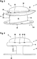
- Fig. 3 shows an aircraft beacon light 2 in accordance with an exemplary embodiment of the invention in a perspective view.
- the aircraft beacon light 2 comprises a support structure 4 and a lighting system 6.
- the support structure 4 comprises a base 48, a stem 42, and a carrier, which is blocked from view in the viewing direction of Fig. 3 .
- the lighting system 6 comprises a plurality of light sources, light optics, and a lens cover 68. In the perspective view of Fig. 3 , only the lens cover 68 is depicted, with the plurality of light sources and the light optics being arranged beneath the lens cover 68.
- the aircraft beacon light 2 further comprises a fastener 8.
- the fastener 8 secures the lens cover 68 in position with respect to the support structure 4, as will be explained in more detail with respect to Fig. 6 .
- the fastener 8 has bolt holes 80, through which bolts may be inserted for securing the fastener and, thus, the lens cover 68 to the carrier of the support structure 4.
- the support structure 4 supports the lighting system 6 and is configured for being mounted to an aircraft fuselage.
- the carrier of the support structure 4 is a disc-shaped structure that supports the lens cover 68 and the other components of the lighting system 6.
- the base 48 is also a disc-shaped structure.
- the base 48 is mountable to the aircraft fuselage.
- the stem 42 spaces the base 48 from the carrier. In this way, the stem 42 spaces the lighting system 6 from the aircraft fuselage, when the aircraft beacon light 2 is installed on the aircraft fuselage.
- the stem 42 has a front end 44 and an aft end 46.
- the stem 42 is an elongated structure, having a significantly greater length than width. When mounted to the aircraft fuselage, the longitudinal extension of the stem 42 from its front end 44 to its aft end 46 is aligned with the longitudinal extension of the aircraft. This is illustrated in Fig. 3 by the indication of the flight direction 150.
- the stem 42 has an airfoil shape between its front end 44 and its aft end 46, as will be described below with respect to Fig. 5 .
- the support structure 4 further comprises two lightning arrestors 52, namely a front lightning arrestor and an aft lighting arrestor.
- the lightning arrestors 52 extend through the fastener 8. They are arranged in close proximity to the perimeter of the lens cover 68.
- the fastener 8 surrounds a proximate portion of the lens cover 68 of the lighting system 6. It provides for a clamping of the lens cover 68 to the support structure 4 all around the perimeter of the lens cover 68.
- the fastener 8 is also shaped for aerodynamic efficiency.
- Fig. 4 shows the aircraft beacon light 2 of Fig. 3 in a front view.
- the support structure 4 of the aircraft beacon light 2 comprises a base 48, a stem 42, and a carrier 40.
- the underside of the carrier 40 which was blocked from view in the viewing direction of Fig. 3 , can be seen in Fig. 4 .
- the carrier 40 extends to the left and to the right of the stem 42.
- the stem 42 has a much smaller transverse cross-section than the carrier 40. It also has a much smaller transverse cross-section than the base 48.
- the fastener 8 has a somewhat larger transverse extension than the carrier 40 and than the lens cover 68. The fastener 8 surrounds the carrier 40 and the proximate portion of the lens cover 68, securing the lens cover 68 to the carrier 40.
- Fig. 5 shows the aircraft beacon light 2 of Fig. 3 in a horizontal cross-sectional view.
- the cross-sectional plane of Fig. 5 runs through the stem 42.
- the viewing direction is onto the base 48 of the support structure 4.
- the base 48 comprises four mounting holes 50.
- four bolts are inserted through the mounting holes 50, securing the base 48 to the aircraft fuselage.
- the aircraft fuselage may have a recess, corresponding in shape and size to the disc-shaped base 48. In this way, the upper surface of the base 48 may be flush with the outer surface of the aircraft fuselage, when the aircraft beacon light 2 is mounted thereto.
- the stem 42 has an airfoil shape.
- the airfoil shape expands to its largest width fairly closely to the front end 44, while it tapers to the aft end 46 over a large part of its longitudinal extension.
- the airfoil shape is in accordance with the NACA 0012 airfoil specification. It is pointed out that other airfoil shapes are possible as well.
- the stem 42 is hollow.
- the wall structure forming the airfoil is thin, as compared to the outer extension of the stem 42. It is pointed out that the stem 42 may be a solid structure as well.
- Fig. 6 shows the aircraft beacon light 2 of Fig. 3 in a vertical cross-sectional view.
- the cross-sectional plane of Fig. 6 is a longitudinal cross-sectional plane in the aircraft frame of reference and runs through the center of the aircraft beacon light 2. While Fig. 6A shows the aircraft beacon light 2 in its entirety, Fig. 6B shows selected components thereof in an enlarged view.
- the aircraft beacon light 2 comprises a support structure 4 and a lighting system 6.
- the support structure 4 comprises a base 48, a stem 42, and a carrier 40.
- the stem 42 spaces the base 48 from the carrier 40.
- the carrier 40 closes said hollow structure on the distal side.
- the carrier 40 supports the lighting system 6, as will be explained in more detail below.
- the support structure 4 further comprises two lightning arrestors 52, which are arranged on a front portion and an aft portion of the carrier 40.
- the base 48, the stem 42, the carrier 40 and the lightning arrestors 52 are integrally formed.
- the lighting system 6 comprises a plurality of light sources 60, light optics 62, a lens cover 68, a circuit board 70, such as a printed circuit board, and an electric dehumidifier 72.
- the circuit board is mounted to the carrier 40, for example via attachment screws or other suitable attachment means.
- the plurality of light sources 60, the light optics 62, and the electric dehumidifier 72 are mounted to the circuit board 70 and are, thus, supported by the carrier 40.
- the circuit board 70 may carry further components, such as a control unit, and may provide for the electric connections between the components, such as electric connections between an on-board electricity network, the control unit, and the plurality of light sources.
- the lens cover 68 is a dome-shaped structure.
- the proximate portion of the lens cover 68 is placed around a step in the upper surface of the carrier 40. In this way, the lens cover 68 is prevented from lateral movement by the carrier 40.
- the proximate portion of the lens cover 68 is arranged between said step in the upper surface of the carrier 40 and the lightning arrestors 52. In this way, the lightning arrestors 52 are arranged in close vicinity to the perimeter of the lens cover 68.
- the aircraft beacon light 2 further comprises an O-ring 10 that is arranged between the lens cover 68 and the carrier 40 of the support structure 4. With the O-ring 10, an effective sealing of the inner space of the aircraft beacon light 2 between the carrier 40 and the lens cover 68 is achieved.
- the lens cover 68 is clamped to the support structure 4, in particular to the carrier 40 thereof, by fastener 8.
- the plurality of light sources 60, the light optics 62 and the electric dehumidifier 72 are arranged between the carrier 40 and the lens cover 68, i.e. in the inner space of the aircraft beacon light.
- the plurality of light sources 60 are arranged in a circular manner around a central portion 41 of the carrier 40.
- the plurality of light sources 60 are red LEDs in the depicted exemplary embodiment.
- the plurality of light sources 60 face away from the carrier 40.
- the light optics 62 comprise an annular lens structure.
- the annular lens structure is arranged over the plurality of light sources 60, in particular overmolded over the plurality of light sources 60.
- the annular lens structure may be made from silicone or other suitable transparent or translucent material, such as PMMA.
- the annular lens structure has a first total internal reflection surface 64 and a second total internal reflection surface 66.
- the first total internal reflection surface 64 reflects a first portion of light, emitted by the plurality of light sources 60, laterally outwards.
- the second total internal reflection surface 66 reflects a second portion of light, emitted by the plurality of light sources 60, laterally inwards.
- the re-directing of light by the annular lens structure is illustrated via exemplary light rays in Fig. 6 .
- the re-directing of the light from the plurality of LEDs 60 via the first total internal reflection surface 64 and the second total internal reflection surface 66 allows for an efficient fulfilling of the FAR requirements for aircraft beacon lights, while also allowing for a low height of the light optics 62.
- the plurality of light sources 60, the light optics 62, and the lens cover 68 are arranged in a rotationally symmetric manner around an axis of rotation 74.
- the electric dehumidifier 72 is arranged in the center of the annular lens structure.
- the electric dehumidifier is a device that converts water into hydrogen and oxygen with the help of electric energy.
- the generated hydrogen is highly evasive and may escape through the sealing. In this way, water and humidity, build up in the inner space of the aircraft beacon light, may be efficiently removed.
- the spacing of the lighting system 6 from the aircraft fuselage via the stem 42 and the re-directing of light via total internal reflection allow for an efficient fulfilling of the aircraft beacon light functionality with a low height extension of the lighting system 6.
- the lightning arrestors 52 are sufficient for diverting a potential lightning strike from the lens cover 68, although the lightning arrestors are placed around the periphery of the lens cover 68 and have a smaller height extension than the lens cover 68.
- the provision of the lightning arrestors 52 outside of the lens cover 68 eliminates the need for a central lightning arrestor, extending through the lens cover 68. Without such a central lightning arrestor, the sealing of the inner space of the aircraft beacon light 2 may be carried out in a particularly effective manner. This results in a low amount of humidity / water being trapped in the inner space of the aircraft beacon light 2, and this low amount of water / humidity can be conveniently taken care of by the electric dehumidifier 72.
- the opening angles for the light output is about 180°.
- the aircraft beacon light 2 is able to satisfy the FAR requirements for the upper hemisphere or for the lower hemisphere in the aircraft frame of reference.
- the opening angle of the beacon light output may also be more than 180° in one or more or all vertical cross-sections through the aircraft beacon light 2. This may be achieved with a modified geometry of the first total internal reflection surface 64 or with other suitable means for directing the light accordingly.
- the effect of the opening angle of the beacon light output being more than 180° will be illustrated and explained in more detail with respect to Fig. 8 .
- the aircraft beacon light 2 emits a red-flashing beacon light output.
- the plurality of light sources may be controlled to light up in a pulsed manner. Further in particular, the plurality of light sources may be controlled to light up in a pulsed pattern that creates a perception of a sequence of red light flashes for a human observer.
- the aircraft beacon light 2 may comprise a control unit that causes the plurality of light sources to emit a sequence of light flashes.
- the control unit may be coupled to an on-board power supply and may provide current pulses to the plurality of LEDs.
- Fig. 7 shows the circuit board 70, the plurality of light sources 60, the light optics 62, and the electric dehumidifier 72 in a three-dimensional perspective view.
- Fig. 7 shows the annular structure of the light optics 62, including its first total internal reflection surface 64 and its second total internal reflection surface 66, and the arrangement of the plurality of light sources 60 along a circular outline.
- Fig. 8 shows an aircraft 100 in accordance with an exemplary embodiment of the invention, equipped with two aircraft beacon lights 2 in accordance with an exemplary embodiment of the invention.
- the aircraft 100 has an upper beacon light 2 in accordance with an exemplary embodiment of the invention, mounted to a top portion of the aircraft fuselage 104.
- the aircraft 100 has a lower aircraft beacon light 2, mounted to a bottom portion of the aircraft fuselage 104.
- the stem and the lens cover of the aircraft beacon lights 2 are depicted.
- the stem and the lens cover are depicted highly schematically and larger than they would be if depicted to scale. In this way, the spacing of the lens cover and, thus, of the lighting system from the aircraft fuselage 104 is more clearly illustrated.
- Both the upper aircraft beacon light 2 and the lower aircraft beacon light 2 provide for a beacon light output that has an opening angle of more than 180°, indicated by the angle ⁇ in Fig. 8 .
- both depicted aircraft beacon lights 2 provide for a beacon light output that extends to the stem-side of a horizontal reference plane through the plurality of light sources, i.e. to the side of the aircraft fuselage 104 of the horizontal reference plane through the plurality of light sources.
- the upper and lower aircraft beacon lights 2 may help in mitigating the shadowing of the beacon light output, as may be caused by the engines 108, the wing tips 116 or other aircraft structures.
- the beacon light output of the upper aircraft beacon light 2 may fill in the gaps in the beacon light output that are caused by the engines 108 with respect to the light emitted by the lower aircraft beacon light 2.
- the beacon light output of the lower aircraft beacon light 2 may fill in the gaps in the beacon light output that are caused by the wing tips 116 with respect to the light emitted by the upper aircraft beacon light 2.
- exemplary embodiments of the invention may allow for achieving a more complete beacon light output around the aircraft.
- the opening angle ⁇ may for example be between 185° and 210°, in particular between 190° and 200°.
- the opening angle ⁇ being 190° means that the beacon light output extends to an angular range of between 0° and 5° on the stem-side of a horizontal reference plane through the aircraft beacon light 2
- the opening angle ⁇ being 200° means that the beacon light output extends to an angular range of between 0° and 10° on the stem-side of a horizontal reference plane through the aircraft beacon light 2, etc.
Landscapes
- Engineering & Computer Science (AREA)
- Aviation & Aerospace Engineering (AREA)
- General Engineering & Computer Science (AREA)
- Non-Portable Lighting Devices Or Systems Thereof (AREA)
- Traffic Control Systems (AREA)
- Optical Communication System (AREA)
Priority Applications (6)
| Application Number | Priority Date | Filing Date | Title |
|---|---|---|---|
| EP19170233.1A EP3725687B1 (fr) | 2019-04-18 | 2019-04-18 | Balise lumineuse d'aéronef et aéronef comprenant une balise lumineuse |
| ES19170233T ES2938352T3 (es) | 2019-04-18 | 2019-04-18 | Luz de baliza de aeronave y aeronave que comprende una luz de baliza de aeronave |
| CA3063873A CA3063873A1 (fr) | 2019-04-18 | 2019-12-04 | Balise d`aeronef et aeronef comprenant une balise d`aeronef |
| BR102019026033-5A BR102019026033B1 (pt) | 2019-04-18 | 2019-12-09 | Luz de farol de aeronave, e, aeronave |
| US16/712,396 US10974847B2 (en) | 2019-04-18 | 2019-12-12 | Aircraft beacon light and aircraft comprising an aircraft beacon light |
| CN201911285704.7A CN111824435B (zh) | 2019-04-18 | 2019-12-13 | 飞行器信标灯和包括飞行器信标灯的飞行器 |
Applications Claiming Priority (1)
| Application Number | Priority Date | Filing Date | Title |
|---|---|---|---|
| EP19170233.1A EP3725687B1 (fr) | 2019-04-18 | 2019-04-18 | Balise lumineuse d'aéronef et aéronef comprenant une balise lumineuse |
Publications (2)
| Publication Number | Publication Date |
|---|---|
| EP3725687A1 true EP3725687A1 (fr) | 2020-10-21 |
| EP3725687B1 EP3725687B1 (fr) | 2022-11-16 |
Family
ID=66239887
Family Applications (1)
| Application Number | Title | Priority Date | Filing Date |
|---|---|---|---|
| EP19170233.1A Active EP3725687B1 (fr) | 2019-04-18 | 2019-04-18 | Balise lumineuse d'aéronef et aéronef comprenant une balise lumineuse |
Country Status (5)
| Country | Link |
|---|---|
| US (1) | US10974847B2 (fr) |
| EP (1) | EP3725687B1 (fr) |
| CN (1) | CN111824435B (fr) |
| CA (1) | CA3063873A1 (fr) |
| ES (1) | ES2938352T3 (fr) |
Cited By (2)
| Publication number | Priority date | Publication date | Assignee | Title |
|---|---|---|---|---|
| EP4234412A1 (fr) * | 2022-02-23 | 2023-08-30 | Goodrich Lighting Systems GmbH & Co. KG | Lumière d'aéronef, aéronef, et procédé d'assemblage d'une lumière d'aéronef |
| EP4324751A1 (fr) * | 2022-08-18 | 2024-02-21 | Goodrich Lighting Systems GmbH & Co. KG | Couvercle de protection pour feu d'aéronef extérieur monté sur le fuselage et feu d'aéronef extérieur |
Families Citing this family (4)
| Publication number | Priority date | Publication date | Assignee | Title |
|---|---|---|---|---|
| US11325690B1 (en) * | 2020-10-19 | 2022-05-10 | Rockwell Collins, Inc. | Integrated aircraft antenna and light assemblies |
| EP4063278B1 (fr) | 2021-03-25 | 2024-08-28 | Goodrich Lighting Systems GmbH & Co. KG | Lumière anticollision d'aéronef, aéronef comprenant une lumière anticollision d'aéronef et procédé de fonctionnement d'une lumière anticollision d'aéronef |
| EP4124794B1 (fr) | 2021-07-28 | 2025-10-29 | Goodrich Lighting Systems GmbH & Co. KG | Lumière extérieure d'aéronef et aéronef la comprenant |
| US20250108934A1 (en) * | 2023-10-02 | 2025-04-03 | Christian Nielsen | Anti-collision light for aircraft |
Citations (7)
| Publication number | Priority date | Publication date | Assignee | Title |
|---|---|---|---|---|
| GB143095A (en) * | 1919-07-17 | 1920-05-20 | Eben George Balch | Lamp signalling device particularly applicable to aeroplanes |
| US3706968A (en) * | 1970-11-20 | 1972-12-19 | Lockheed Aircraft Corp | Beacon providing visual direction information |
| EP2502828A1 (fr) * | 2011-03-25 | 2012-09-26 | Eurocopter | Surface aérodynamique et aéronef |
| EP3168160A1 (fr) * | 2015-11-13 | 2017-05-17 | Goodrich Lighting Systems GmbH | Unité d'éclairage extérieur d'aéronef et aéronef comprenant celle-ci |
| US20170138584A1 (en) * | 2015-11-13 | 2017-05-18 | Goodrich Lighting Systems Gmbh | Exterior Aircraft Light Unit |
| US9771168B2 (en) * | 2011-09-26 | 2017-09-26 | Goodrich Lighting Systems Gmbh | Aircraft light |
| US10156627B2 (en) * | 2015-10-15 | 2018-12-18 | uAvionix Corporation | Aircraft navigation light ADS-B radio |
Family Cites Families (13)
| Publication number | Priority date | Publication date | Assignee | Title |
|---|---|---|---|---|
| US1828097A (en) | 1923-11-06 | 1931-10-20 | Pioneer Instr Co Inc | Aircraft navigation light |
| ES2173429T3 (es) | 1996-11-12 | 2002-10-16 | L F D Ltd | Lampara |
| US5813744A (en) | 1997-03-17 | 1998-09-29 | Mcdonnell Douglas Corp. | Aircraft ground floodlight |
| US7079041B2 (en) * | 2003-11-21 | 2006-07-18 | Whelen Engineering Company, Inc. | LED aircraft anticollision beacon |
| WO2015136307A1 (fr) * | 2014-03-14 | 2015-09-17 | Saf-T-Glo Limited | Systèmes d'éclairage |
| EP2924340B1 (fr) * | 2014-03-28 | 2019-05-01 | Goodrich Lighting Systems GmbH | Unité de lumière extérieure pour aéronef ou autre véhicule et aéronef comprenant ladite unité |
| EP3284684B1 (fr) * | 2016-08-19 | 2019-07-24 | Goodrich Lighting Systems GmbH | Unité de lumière d'avion extérieure et procédé d'avertissement personnel au sol |
| EP3284683B1 (fr) * | 2016-08-19 | 2019-07-31 | Goodrich Lighting Systems GmbH | Unité d'éclairage extérieur d'aéronef, hélicoptère et aéronef |
| US10435175B2 (en) | 2017-01-31 | 2019-10-08 | Honeywell International Inc. | Light emitting diode lamp assembly |
| EP3360798B1 (fr) * | 2017-02-10 | 2019-12-25 | Goodrich Lighting Systems GmbH | Unité d'aéronef d'éclairage du sol |
| US10086953B1 (en) * | 2017-03-20 | 2018-10-02 | Honeywell International Inc. | Aircraft beacon light synchronization |
| EP3403934B1 (fr) * | 2017-05-19 | 2021-01-27 | Goodrich Lighting Systems GmbH | Soupape de vidange, unité d'éclairage d'aéronef extérieure et boîtier d'alimentation |
| CN208442772U (zh) * | 2018-07-18 | 2019-01-29 | 深圳市大疆创新科技有限公司 | 探照灯及无人飞行器组件 |
-
2019
- 2019-04-18 ES ES19170233T patent/ES2938352T3/es active Active
- 2019-04-18 EP EP19170233.1A patent/EP3725687B1/fr active Active
- 2019-12-04 CA CA3063873A patent/CA3063873A1/fr active Pending
- 2019-12-12 US US16/712,396 patent/US10974847B2/en active Active
- 2019-12-13 CN CN201911285704.7A patent/CN111824435B/zh active Active
Patent Citations (7)
| Publication number | Priority date | Publication date | Assignee | Title |
|---|---|---|---|---|
| GB143095A (en) * | 1919-07-17 | 1920-05-20 | Eben George Balch | Lamp signalling device particularly applicable to aeroplanes |
| US3706968A (en) * | 1970-11-20 | 1972-12-19 | Lockheed Aircraft Corp | Beacon providing visual direction information |
| EP2502828A1 (fr) * | 2011-03-25 | 2012-09-26 | Eurocopter | Surface aérodynamique et aéronef |
| US9771168B2 (en) * | 2011-09-26 | 2017-09-26 | Goodrich Lighting Systems Gmbh | Aircraft light |
| US10156627B2 (en) * | 2015-10-15 | 2018-12-18 | uAvionix Corporation | Aircraft navigation light ADS-B radio |
| EP3168160A1 (fr) * | 2015-11-13 | 2017-05-17 | Goodrich Lighting Systems GmbH | Unité d'éclairage extérieur d'aéronef et aéronef comprenant celle-ci |
| US20170138584A1 (en) * | 2015-11-13 | 2017-05-18 | Goodrich Lighting Systems Gmbh | Exterior Aircraft Light Unit |
Cited By (4)
| Publication number | Priority date | Publication date | Assignee | Title |
|---|---|---|---|---|
| EP4234412A1 (fr) * | 2022-02-23 | 2023-08-30 | Goodrich Lighting Systems GmbH & Co. KG | Lumière d'aéronef, aéronef, et procédé d'assemblage d'une lumière d'aéronef |
| US11905035B2 (en) | 2022-02-23 | 2024-02-20 | Goodrich Lighting Systems GmbH & Co. KG | Aircraft light, aircraft, and method of assembling an aircraft light |
| EP4324751A1 (fr) * | 2022-08-18 | 2024-02-21 | Goodrich Lighting Systems GmbH & Co. KG | Couvercle de protection pour feu d'aéronef extérieur monté sur le fuselage et feu d'aéronef extérieur |
| US12072078B2 (en) | 2022-08-18 | 2024-08-27 | Goodrich Lighting Systems GmbH & Co. KG | Protective cover for a fuselage-mounted exterior aircraft light and exterior aircraft light |
Also Published As
| Publication number | Publication date |
|---|---|
| CA3063873A1 (fr) | 2020-10-18 |
| EP3725687B1 (fr) | 2022-11-16 |
| US10974847B2 (en) | 2021-04-13 |
| US20200331629A1 (en) | 2020-10-22 |
| BR102019026033A2 (pt) | 2020-10-27 |
| CN111824435B (zh) | 2025-02-25 |
| ES2938352T3 (es) | 2023-04-10 |
| CN111824435A (zh) | 2020-10-27 |
Similar Documents
| Publication | Publication Date | Title |
|---|---|---|
| US10974847B2 (en) | Aircraft beacon light and aircraft comprising an aircraft beacon light | |
| US11097855B2 (en) | Aircraft beacon light and aircraft comprising an aircraft beacon light | |
| CN107757936B (zh) | 外部飞机灯单元和警示地面人员的方法 | |
| EP3670356B1 (fr) | Feu combiné de navigation avant et d'anticollision pour aéronef et aéronef le comprenant | |
| CN107757937B (zh) | 外部飞行器灯单元、直升飞机和飞机 | |
| ES2728298T3 (es) | Unidad de iluminación de aeronaves para la iluminación en tierra y aeronaves que comprenden la misma | |
| US11479366B2 (en) | Exterior aircraft light, aircraft comprising the same, and method of operating an exterior aircraft light | |
| US11465773B2 (en) | Aircraft beacon light unit and set of aircraft beacon light units | |
| EP3269649B1 (fr) | Unité d'éclairage extérieur d'aéronef et aéronef comprenant celle-ci | |
| US8956023B1 (en) | Combined wing scan and winglet illumination light unit and aircraft having winglet illumination | |
| US9783319B2 (en) | Exterior aircraft light unit and aircraft comprising the same | |
| EP3168160B1 (fr) | Unité d'éclairage extérieur d'aéronef et aéronef comprenant celle-ci | |
| US11260989B2 (en) | Aircraft beacon light, aircraft wing, aircraft beacon light system, and method of supplementing an aircraft beacon light system | |
| EP3527498B1 (fr) | Lumière d'éclairage de stabilisateur vertical d'aéronef et aéronef la comprenant | |
| EP4234412B1 (fr) | Lumière d'aéronef, aéronef, et procédé d'assemblage d'une lumière d'aéronef | |
| BR102019026033B1 (pt) | Luz de farol de aeronave, e, aeronave | |
| EP4696607A1 (fr) | Feu de navigation de queue d'aéronef, aéronef comprenant un feu de navigation de queue d'aéronef et procédé de fonctionnement d'un feu de navigation de queue d'aéronef |
Legal Events
| Date | Code | Title | Description |
|---|---|---|---|
| PUAI | Public reference made under article 153(3) epc to a published international application that has entered the european phase |
Free format text: ORIGINAL CODE: 0009012 |
|
| STAA | Information on the status of an ep patent application or granted ep patent |
Free format text: STATUS: THE APPLICATION HAS BEEN PUBLISHED |
|
| AK | Designated contracting states |
Kind code of ref document: A1 Designated state(s): AL AT BE BG CH CY CZ DE DK EE ES FI FR GB GR HR HU IE IS IT LI LT LU LV MC MK MT NL NO PL PT RO RS SE SI SK SM TR |
|
| AX | Request for extension of the european patent |
Extension state: BA ME |
|
| STAA | Information on the status of an ep patent application or granted ep patent |
Free format text: STATUS: REQUEST FOR EXAMINATION WAS MADE |
|
| 17P | Request for examination filed |
Effective date: 20210420 |
|
| RBV | Designated contracting states (corrected) |
Designated state(s): AL AT BE BG CH CY CZ DE DK EE ES FI FR GB GR HR HU IE IS IT LI LT LU LV MC MK MT NL NO PL PT RO RS SE SI SK SM TR |
|
| GRAP | Despatch of communication of intention to grant a patent |
Free format text: ORIGINAL CODE: EPIDOSNIGR1 |
|
| STAA | Information on the status of an ep patent application or granted ep patent |
Free format text: STATUS: GRANT OF PATENT IS INTENDED |
|
| INTG | Intention to grant announced |
Effective date: 20220525 |
|
| GRAS | Grant fee paid |
Free format text: ORIGINAL CODE: EPIDOSNIGR3 |
|
| GRAA | (expected) grant |
Free format text: ORIGINAL CODE: 0009210 |
|
| STAA | Information on the status of an ep patent application or granted ep patent |
Free format text: STATUS: THE PATENT HAS BEEN GRANTED |
|
| AK | Designated contracting states |
Kind code of ref document: B1 Designated state(s): AL AT BE BG CH CY CZ DE DK EE ES FI FR GB GR HR HU IE IS IT LI LT LU LV MC MK MT NL NO PL PT RO RS SE SI SK SM TR |
|
| REG | Reference to a national code |
Ref country code: GB Ref legal event code: FG4D |
|
| REG | Reference to a national code |
Ref country code: CH Ref legal event code: EP |
|
| REG | Reference to a national code |
Ref country code: IE Ref legal event code: FG4D |
|
| REG | Reference to a national code |
Ref country code: DE Ref legal event code: R096 Ref document number: 602019021890 Country of ref document: DE |
|
| REG | Reference to a national code |
Ref country code: AT Ref legal event code: REF Ref document number: 1531651 Country of ref document: AT Kind code of ref document: T Effective date: 20221215 |
|
| REG | Reference to a national code |
Ref country code: LT Ref legal event code: MG9D |
|
| REG | Reference to a national code |
Ref country code: NL Ref legal event code: MP Effective date: 20221116 |
|
| REG | Reference to a national code |
Ref country code: ES Ref legal event code: FG2A Ref document number: 2938352 Country of ref document: ES Kind code of ref document: T3 Effective date: 20230410 |
|
| REG | Reference to a national code |
Ref country code: AT Ref legal event code: MK05 Ref document number: 1531651 Country of ref document: AT Kind code of ref document: T Effective date: 20221116 |
|
| PG25 | Lapsed in a contracting state [announced via postgrant information from national office to epo] |
Ref country code: SE Free format text: LAPSE BECAUSE OF FAILURE TO SUBMIT A TRANSLATION OF THE DESCRIPTION OR TO PAY THE FEE WITHIN THE PRESCRIBED TIME-LIMIT Effective date: 20221116 Ref country code: PT Free format text: LAPSE BECAUSE OF FAILURE TO SUBMIT A TRANSLATION OF THE DESCRIPTION OR TO PAY THE FEE WITHIN THE PRESCRIBED TIME-LIMIT Effective date: 20230316 Ref country code: NO Free format text: LAPSE BECAUSE OF FAILURE TO SUBMIT A TRANSLATION OF THE DESCRIPTION OR TO PAY THE FEE WITHIN THE PRESCRIBED TIME-LIMIT Effective date: 20230216 Ref country code: LT Free format text: LAPSE BECAUSE OF FAILURE TO SUBMIT A TRANSLATION OF THE DESCRIPTION OR TO PAY THE FEE WITHIN THE PRESCRIBED TIME-LIMIT Effective date: 20221116 Ref country code: FI Free format text: LAPSE BECAUSE OF FAILURE TO SUBMIT A TRANSLATION OF THE DESCRIPTION OR TO PAY THE FEE WITHIN THE PRESCRIBED TIME-LIMIT Effective date: 20221116 Ref country code: AT Free format text: LAPSE BECAUSE OF FAILURE TO SUBMIT A TRANSLATION OF THE DESCRIPTION OR TO PAY THE FEE WITHIN THE PRESCRIBED TIME-LIMIT Effective date: 20221116 |
|
| PG25 | Lapsed in a contracting state [announced via postgrant information from national office to epo] |
Ref country code: RS Free format text: LAPSE BECAUSE OF FAILURE TO SUBMIT A TRANSLATION OF THE DESCRIPTION OR TO PAY THE FEE WITHIN THE PRESCRIBED TIME-LIMIT Effective date: 20221116 Ref country code: PL Free format text: LAPSE BECAUSE OF FAILURE TO SUBMIT A TRANSLATION OF THE DESCRIPTION OR TO PAY THE FEE WITHIN THE PRESCRIBED TIME-LIMIT Effective date: 20221116 Ref country code: LV Free format text: LAPSE BECAUSE OF FAILURE TO SUBMIT A TRANSLATION OF THE DESCRIPTION OR TO PAY THE FEE WITHIN THE PRESCRIBED TIME-LIMIT Effective date: 20221116 Ref country code: IS Free format text: LAPSE BECAUSE OF FAILURE TO SUBMIT A TRANSLATION OF THE DESCRIPTION OR TO PAY THE FEE WITHIN THE PRESCRIBED TIME-LIMIT Effective date: 20230316 Ref country code: HR Free format text: LAPSE BECAUSE OF FAILURE TO SUBMIT A TRANSLATION OF THE DESCRIPTION OR TO PAY THE FEE WITHIN THE PRESCRIBED TIME-LIMIT Effective date: 20221116 Ref country code: GR Free format text: LAPSE BECAUSE OF FAILURE TO SUBMIT A TRANSLATION OF THE DESCRIPTION OR TO PAY THE FEE WITHIN THE PRESCRIBED TIME-LIMIT Effective date: 20230217 |
|
| PG25 | Lapsed in a contracting state [announced via postgrant information from national office to epo] |
Ref country code: NL Free format text: LAPSE BECAUSE OF FAILURE TO SUBMIT A TRANSLATION OF THE DESCRIPTION OR TO PAY THE FEE WITHIN THE PRESCRIBED TIME-LIMIT Effective date: 20221116 |
|
| PG25 | Lapsed in a contracting state [announced via postgrant information from national office to epo] |
Ref country code: SM Free format text: LAPSE BECAUSE OF FAILURE TO SUBMIT A TRANSLATION OF THE DESCRIPTION OR TO PAY THE FEE WITHIN THE PRESCRIBED TIME-LIMIT Effective date: 20221116 Ref country code: RO Free format text: LAPSE BECAUSE OF FAILURE TO SUBMIT A TRANSLATION OF THE DESCRIPTION OR TO PAY THE FEE WITHIN THE PRESCRIBED TIME-LIMIT Effective date: 20221116 Ref country code: EE Free format text: LAPSE BECAUSE OF FAILURE TO SUBMIT A TRANSLATION OF THE DESCRIPTION OR TO PAY THE FEE WITHIN THE PRESCRIBED TIME-LIMIT Effective date: 20221116 Ref country code: DK Free format text: LAPSE BECAUSE OF FAILURE TO SUBMIT A TRANSLATION OF THE DESCRIPTION OR TO PAY THE FEE WITHIN THE PRESCRIBED TIME-LIMIT Effective date: 20221116 Ref country code: CZ Free format text: LAPSE BECAUSE OF FAILURE TO SUBMIT A TRANSLATION OF THE DESCRIPTION OR TO PAY THE FEE WITHIN THE PRESCRIBED TIME-LIMIT Effective date: 20221116 |
|
| P01 | Opt-out of the competence of the unified patent court (upc) registered |
Effective date: 20230630 |
|
| REG | Reference to a national code |
Ref country code: DE Ref legal event code: R097 Ref document number: 602019021890 Country of ref document: DE |
|
| PG25 | Lapsed in a contracting state [announced via postgrant information from national office to epo] |
Ref country code: SK Free format text: LAPSE BECAUSE OF FAILURE TO SUBMIT A TRANSLATION OF THE DESCRIPTION OR TO PAY THE FEE WITHIN THE PRESCRIBED TIME-LIMIT Effective date: 20221116 Ref country code: AL Free format text: LAPSE BECAUSE OF FAILURE TO SUBMIT A TRANSLATION OF THE DESCRIPTION OR TO PAY THE FEE WITHIN THE PRESCRIBED TIME-LIMIT Effective date: 20221116 |
|
| PLBE | No opposition filed within time limit |
Free format text: ORIGINAL CODE: 0009261 |
|
| STAA | Information on the status of an ep patent application or granted ep patent |
Free format text: STATUS: NO OPPOSITION FILED WITHIN TIME LIMIT |
|
| 26N | No opposition filed |
Effective date: 20230817 |
|
| PG25 | Lapsed in a contracting state [announced via postgrant information from national office to epo] |
Ref country code: SI Free format text: LAPSE BECAUSE OF FAILURE TO SUBMIT A TRANSLATION OF THE DESCRIPTION OR TO PAY THE FEE WITHIN THE PRESCRIBED TIME-LIMIT Effective date: 20221116 |
|
| REG | Reference to a national code |
Ref country code: CH Ref legal event code: PL |
|
| PG25 | Lapsed in a contracting state [announced via postgrant information from national office to epo] |
Ref country code: LU Free format text: LAPSE BECAUSE OF NON-PAYMENT OF DUE FEES Effective date: 20230418 |
|
| REG | Reference to a national code |
Ref country code: BE Ref legal event code: MM Effective date: 20230430 |
|
| PG25 | Lapsed in a contracting state [announced via postgrant information from national office to epo] |
Ref country code: MC Free format text: LAPSE BECAUSE OF FAILURE TO SUBMIT A TRANSLATION OF THE DESCRIPTION OR TO PAY THE FEE WITHIN THE PRESCRIBED TIME-LIMIT Effective date: 20221116 |
|
| PG25 | Lapsed in a contracting state [announced via postgrant information from national office to epo] |
Ref country code: MC Free format text: LAPSE BECAUSE OF FAILURE TO SUBMIT A TRANSLATION OF THE DESCRIPTION OR TO PAY THE FEE WITHIN THE PRESCRIBED TIME-LIMIT Effective date: 20221116 Ref country code: LI Free format text: LAPSE BECAUSE OF NON-PAYMENT OF DUE FEES Effective date: 20230430 Ref country code: CH Free format text: LAPSE BECAUSE OF NON-PAYMENT OF DUE FEES Effective date: 20230430 |
|
| REG | Reference to a national code |
Ref country code: IE Ref legal event code: MM4A |
|
| PG25 | Lapsed in a contracting state [announced via postgrant information from national office to epo] |
Ref country code: BE Free format text: LAPSE BECAUSE OF NON-PAYMENT OF DUE FEES Effective date: 20230430 |
|
| PG25 | Lapsed in a contracting state [announced via postgrant information from national office to epo] |
Ref country code: IE Free format text: LAPSE BECAUSE OF NON-PAYMENT OF DUE FEES Effective date: 20230418 |
|
| PG25 | Lapsed in a contracting state [announced via postgrant information from national office to epo] |
Ref country code: IE Free format text: LAPSE BECAUSE OF NON-PAYMENT OF DUE FEES Effective date: 20230418 |
|
| PG25 | Lapsed in a contracting state [announced via postgrant information from national office to epo] |
Ref country code: IT Free format text: LAPSE BECAUSE OF FAILURE TO SUBMIT A TRANSLATION OF THE DESCRIPTION OR TO PAY THE FEE WITHIN THE PRESCRIBED TIME-LIMIT Effective date: 20221116 |
|
| PG25 | Lapsed in a contracting state [announced via postgrant information from national office to epo] |
Ref country code: BG Free format text: LAPSE BECAUSE OF FAILURE TO SUBMIT A TRANSLATION OF THE DESCRIPTION OR TO PAY THE FEE WITHIN THE PRESCRIBED TIME-LIMIT Effective date: 20221116 |
|
| PG25 | Lapsed in a contracting state [announced via postgrant information from national office to epo] |
Ref country code: BG Free format text: LAPSE BECAUSE OF FAILURE TO SUBMIT A TRANSLATION OF THE DESCRIPTION OR TO PAY THE FEE WITHIN THE PRESCRIBED TIME-LIMIT Effective date: 20221116 |
|
| PGFP | Annual fee paid to national office [announced via postgrant information from national office to epo] |
Ref country code: DE Payment date: 20250319 Year of fee payment: 7 |
|
| PGFP | Annual fee paid to national office [announced via postgrant information from national office to epo] |
Ref country code: ES Payment date: 20250502 Year of fee payment: 7 |
|
| PG25 | Lapsed in a contracting state [announced via postgrant information from national office to epo] |
Ref country code: CY Free format text: LAPSE BECAUSE OF FAILURE TO SUBMIT A TRANSLATION OF THE DESCRIPTION OR TO PAY THE FEE WITHIN THE PRESCRIBED TIME-LIMIT; INVALID AB INITIO Effective date: 20190418 |
|
| PG25 | Lapsed in a contracting state [announced via postgrant information from national office to epo] |
Ref country code: HU Free format text: LAPSE BECAUSE OF FAILURE TO SUBMIT A TRANSLATION OF THE DESCRIPTION OR TO PAY THE FEE WITHIN THE PRESCRIBED TIME-LIMIT; INVALID AB INITIO Effective date: 20190418 |
|
| PG25 | Lapsed in a contracting state [announced via postgrant information from national office to epo] |
Ref country code: TR Free format text: LAPSE BECAUSE OF FAILURE TO SUBMIT A TRANSLATION OF THE DESCRIPTION OR TO PAY THE FEE WITHIN THE PRESCRIBED TIME-LIMIT Effective date: 20221116 |
|
| PGFP | Annual fee paid to national office [announced via postgrant information from national office to epo] |
Ref country code: GB Payment date: 20260319 Year of fee payment: 8 |
|
| PGFP | Annual fee paid to national office [announced via postgrant information from national office to epo] |
Ref country code: FR Payment date: 20260319 Year of fee payment: 8 |