EP3726010B1 - Aktive multieffektorspaltsteuerung in hochdruckturbinen - Google Patents
Aktive multieffektorspaltsteuerung in hochdruckturbinen Download PDFInfo
- Publication number
- EP3726010B1 EP3726010B1 EP20169684.6A EP20169684A EP3726010B1 EP 3726010 B1 EP3726010 B1 EP 3726010B1 EP 20169684 A EP20169684 A EP 20169684A EP 3726010 B1 EP3726010 B1 EP 3726010B1
- Authority
- EP
- European Patent Office
- Prior art keywords
- high pressure
- pressure turbine
- engine
- rotor
- acceleration
- Prior art date
- Legal status (The legal status is an assumption and is not a legal conclusion. Google has not performed a legal analysis and makes no representation as to the accuracy of the status listed.)
- Active
Links
Images
Classifications
-
- F—MECHANICAL ENGINEERING; LIGHTING; HEATING; WEAPONS; BLASTING
- F02—COMBUSTION ENGINES; HOT-GAS OR COMBUSTION-PRODUCT ENGINE PLANTS
- F02C—GAS-TURBINE PLANTS; AIR INTAKES FOR JET-PROPULSION PLANTS; CONTROLLING FUEL SUPPLY IN AIR-BREATHING JET-PROPULSION PLANTS
- F02C9/00—Controlling gas-turbine plants; Controlling fuel supply in air- breathing jet-propulsion plants
- F02C9/48—Control of fuel supply conjointly with another control of the plant
- F02C9/50—Control of fuel supply conjointly with another control of the plant with control of working fluid flow
- F02C9/54—Control of fuel supply conjointly with another control of the plant with control of working fluid flow by throttling the working fluid, by adjusting vanes
-
- F—MECHANICAL ENGINEERING; LIGHTING; HEATING; WEAPONS; BLASTING
- F01—MACHINES OR ENGINES IN GENERAL; ENGINE PLANTS IN GENERAL; STEAM ENGINES
- F01D—NON-POSITIVE DISPLACEMENT MACHINES OR ENGINES, e.g. STEAM TURBINES
- F01D11/00—Preventing or minimising internal leakage of working-fluid, e.g. between stages
- F01D11/08—Preventing or minimising internal leakage of working-fluid, e.g. between stages for sealing space between rotor blade tips and stator
- F01D11/14—Adjusting or regulating tip-clearance, i.e. distance between rotor-blade tips and stator casing
-
- F—MECHANICAL ENGINEERING; LIGHTING; HEATING; WEAPONS; BLASTING
- F01—MACHINES OR ENGINES IN GENERAL; ENGINE PLANTS IN GENERAL; STEAM ENGINES
- F01D—NON-POSITIVE DISPLACEMENT MACHINES OR ENGINES, e.g. STEAM TURBINES
- F01D11/00—Preventing or minimising internal leakage of working-fluid, e.g. between stages
- F01D11/08—Preventing or minimising internal leakage of working-fluid, e.g. between stages for sealing space between rotor blade tips and stator
- F01D11/14—Adjusting or regulating tip-clearance, i.e. distance between rotor-blade tips and stator casing
- F01D11/20—Actively adjusting tip-clearance
- F01D11/24—Actively adjusting tip-clearance by selectively cooling-heating stator or rotor components
-
- F—MECHANICAL ENGINEERING; LIGHTING; HEATING; WEAPONS; BLASTING
- F02—COMBUSTION ENGINES; HOT-GAS OR COMBUSTION-PRODUCT ENGINE PLANTS
- F02C—GAS-TURBINE PLANTS; AIR INTAKES FOR JET-PROPULSION PLANTS; CONTROLLING FUEL SUPPLY IN AIR-BREATHING JET-PROPULSION PLANTS
- F02C6/00—Plural gas-turbine plants; Combinations of gas-turbine plants with other apparatus; Adaptations of gas-turbine plants for special use
- F02C6/04—Gas-turbine plants providing heated or pressurised working fluid for other apparatus, e.g. without mechanical power output
- F02C6/06—Gas-turbine plants providing heated or pressurised working fluid for other apparatus, e.g. without mechanical power output providing compressed gas
-
- F—MECHANICAL ENGINEERING; LIGHTING; HEATING; WEAPONS; BLASTING
- F02—COMBUSTION ENGINES; HOT-GAS OR COMBUSTION-PRODUCT ENGINE PLANTS
- F02C—GAS-TURBINE PLANTS; AIR INTAKES FOR JET-PROPULSION PLANTS; CONTROLLING FUEL SUPPLY IN AIR-BREATHING JET-PROPULSION PLANTS
- F02C9/00—Controlling gas-turbine plants; Controlling fuel supply in air- breathing jet-propulsion plants
- F02C9/16—Control of working fluid flow
- F02C9/20—Control of working fluid flow by throttling; by adjusting vanes
-
- F—MECHANICAL ENGINEERING; LIGHTING; HEATING; WEAPONS; BLASTING
- F01—MACHINES OR ENGINES IN GENERAL; ENGINE PLANTS IN GENERAL; STEAM ENGINES
- F01D—NON-POSITIVE DISPLACEMENT MACHINES OR ENGINES, e.g. STEAM TURBINES
- F01D11/00—Preventing or minimising internal leakage of working-fluid, e.g. between stages
- F01D11/08—Preventing or minimising internal leakage of working-fluid, e.g. between stages for sealing space between rotor blade tips and stator
- F01D11/14—Adjusting or regulating tip-clearance, i.e. distance between rotor-blade tips and stator casing
- F01D11/20—Actively adjusting tip-clearance
-
- F—MECHANICAL ENGINEERING; LIGHTING; HEATING; WEAPONS; BLASTING
- F01—MACHINES OR ENGINES IN GENERAL; ENGINE PLANTS IN GENERAL; STEAM ENGINES
- F01D—NON-POSITIVE DISPLACEMENT MACHINES OR ENGINES, e.g. STEAM TURBINES
- F01D11/00—Preventing or minimising internal leakage of working-fluid, e.g. between stages
- F01D11/08—Preventing or minimising internal leakage of working-fluid, e.g. between stages for sealing space between rotor blade tips and stator
- F01D11/14—Adjusting or regulating tip-clearance, i.e. distance between rotor-blade tips and stator casing
- F01D11/20—Actively adjusting tip-clearance
- F01D11/22—Actively adjusting tip-clearance by mechanically actuating the stator or rotor components, e.g. moving shroud sections relative to the rotor
-
- F—MECHANICAL ENGINEERING; LIGHTING; HEATING; WEAPONS; BLASTING
- F02—COMBUSTION ENGINES; HOT-GAS OR COMBUSTION-PRODUCT ENGINE PLANTS
- F02K—JET-PROPULSION PLANTS
- F02K3/00—Plants including a gas turbine driving a compressor or a ducted fan
- F02K3/02—Plants including a gas turbine driving a compressor or a ducted fan in which part of the working fluid by-passes the turbine and combustion chamber
- F02K3/04—Plants including a gas turbine driving a compressor or a ducted fan in which part of the working fluid by-passes the turbine and combustion chamber the plant including ducted fans, i.e. fans with high volume, low pressure outputs, for augmenting the jet thrust, e.g. of double-flow type
- F02K3/075—Plants including a gas turbine driving a compressor or a ducted fan in which part of the working fluid by-passes the turbine and combustion chamber the plant including ducted fans, i.e. fans with high volume, low pressure outputs, for augmenting the jet thrust, e.g. of double-flow type controlling flow ratio between flows
-
- F—MECHANICAL ENGINEERING; LIGHTING; HEATING; WEAPONS; BLASTING
- F05—INDEXING SCHEMES RELATING TO ENGINES OR PUMPS IN VARIOUS SUBCLASSES OF CLASSES F01-F04
- F05D—INDEXING SCHEME FOR ASPECTS RELATING TO NON-POSITIVE-DISPLACEMENT MACHINES OR ENGINES, GAS-TURBINES OR JET-PROPULSION PLANTS
- F05D2270/00—Control
- F05D2270/01—Purpose of the control system
- F05D2270/04—Purpose of the control system to control acceleration (u)
Definitions
- the present invention is related to gas turbine engines in general and to a method of operating a gas turbine engine and a corresponding gas turbine engine in particular.
- the active clearance control system on typical gas turbine engines allows for fuel burn and high pressure turbine (HPT) efficiency improvements and prolonged engine hot-section life.
- the current process utilizes a modulating butterfly valve that regulates bypass airflow around the circumference of the high pressure turbine case in order to reduce the clearances between the blades of the rotating turbomachinery and the outer air seals mounted in the stationary case. Due to the slow nature of the thermal transients through which the clearances are controlled, relative to the acceleration capabilities of the engine, there is a need to introduce an additional control mode in order to improve clearance control during engine transients. Being able to protect the engine from turbine rubs during the transient would allow the target clearance during cruise to be brought tighter, bringing more fuel burn and efficiency benefit.
- GB 2057574 A discloses a system for controlling the clearance between an outer air seal and turbine rotor blades by controlled modulating flow of cooling air directed from tubes onto the air seal supporting structure.
- US 2001/001845 A1 discloses a method and an apparatus for determining the clearance between the rotor blades of a rotor assembly and a shroud disposed radially outside of the rotor assembly.
- a method of operating a gas turbine engine is provided as described by claim 1.
- modulating the fuel flow is reducing a rate of the fuel flow.
- the reducing the acceleration rate of a high pressure turbine rotor prevents a rub condition between the blade outer airseal and the high pressure turbine rotor during the acceleration of the gas turbine engine.
- modulating the fuel flow is reducing a rate of the fuel flow.
- the blade outer airseal may be disposed in a high pressure turbine case.
- reducing the acceleration rate of a high pressure turbine rotor prevents a rub condition between the blade outer airseal and the high pressure turbine rotor during the acceleration of the gas turbine engine.
- the plurality of variable pitch stator vanes may be rotatable about a vane axis to move between the open position and the closed position.
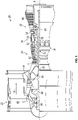
- FIG. 1 schematically illustrates a gas turbine engine 20.
- the gas turbine engine 20 is disclosed herein as a two-spool turbofan that generally incorporates a fan section 22, a compressor section 24, a combustor section 26 and a turbine section 28.
- Alternative engines might include other systems or features.
- the fan section 22 drives air along a bypass flow path B in a bypass duct, while the compressor section 24 drives air along a core flow path C for compression and communication into the combustor section 26 then expansion through the turbine section 28.
- FIG. 1 schematically illustrates a gas turbine engine 20.
- the gas turbine engine 20 is disclosed herein as a two-spool turbofan that generally incorporates a fan section 22, a compressor section 24, a combustor section 26 and a turbine section 28.
- Alternative engines might include other systems or features.
- the fan section 22 drives air along a bypass flow path B in a bypass duct
- the compressor section 24 drives air along a core flow path C for compression and communication into the combustor section 26
- the exemplary engine 20 generally includes a low speed spool 30 and a high speed spool 32 mounted for rotation about an engine central longitudinal axis A relative to an engine static structure 36 via several bearing systems 38. It should be understood that various bearing systems 38 at various locations may alternatively or additionally be provided, and the location of bearing systems 38 may be varied as appropriate to the application.
- the low speed spool 30 generally includes an inner shaft 40 that interconnects a fan 42, a low pressure compressor 44 and a low pressure turbine 46.
- the inner shaft 40 is connected to the fan 42 through a speed change mechanism, which in exemplary gas turbine engine 20 is illustrated as a geared architecture 48 to drive the fan 42 at a lower speed than the low speed spool 30.
- the high speed spool 32 includes an outer shaft 50 that interconnects a high pressure compressor 52 and high pressure turbine 54.
- a combustor 56 is arranged in exemplary gas turbine 20 between the high pressure compressor 52 and the high pressure turbine 54.
- An engine static structure 36 is arranged generally between the high pressure turbine 54 and the low pressure turbine 46.
- the engine static structure 36 further supports bearing systems 38 in the turbine section 28.
- the inner shaft 40 and the outer shaft 50 are concentric and rotate via bearing systems 38 about the engine central longitudinal axis A which is collinear with their longitudinal axes.
- each of the positions of the fan section 22, compressor section 24, combustor section 26, turbine section 28, and fan drive gear system 48 may be varied.
- gear system 48 may be located aft of combustor section 26 or even aft of turbine section 28, and fan section 22 may be positioned forward or aft of the location of gear system 48.
- the engine 20 in one example is a high-bypass geared aircraft engine.
- the engine 20 bypass ratio is greater than about six (6), with an example embodiment being greater than about ten (10)
- the geared architecture 48 is an epicyclic gear train, such as a planetary gear system or other gear system, with a gear reduction ratio of greater than about 2.3 and the low pressure turbine 46 has a pressure ratio that is greater than about five.
- the engine 20 bypass ratio is greater than about ten (10:1)
- the fan diameter is significantly larger than that of the low pressure compressor 44
- the low pressure turbine 46 has a pressure ratio that is greater than about five (5:1).
- Low pressure turbine 46 pressure ratio is pressure measured prior to inlet of low pressure turbine 46 as related to the pressure at the outlet of the low pressure turbine 46 prior to an exhaust nozzle.
- the geared architecture 48 may be an epicyclic gear train, such as a planetary gear system or other gear system, with a gear reduction ratio of greater than about 2.3:1. It should be understood, however, that the above parameters are only exemplary of one embodiment of a geared architecture engine and that the present disclosure is applicable to other gas turbine engines including direct drive turbofans.
- the fan section 22 of the engine 20 is designed for a particular flight condition--typically cruise at about 0.8 Mach and about 35,000 feet (10,668 meters).
- 'TSFC' Thrust Specific Fuel Consumption
- Low fan pressure ratio is the pressure ratio across the fan blade alone, without a Fan Exit Guide Vane (“FEGV”) system.
- the low fan pressure ratio as disclosed herein according to one non-limiting embodiment is less than about 1.45.
- Low corrected fan tip speed is the actual fan tip speed in ft/sec divided by an industry standard temperature correction of [(Tram °R)/(518.7 °R)] 0.5 .
- the "Low corrected fan tip speed” as disclosed herein according to one non-limiting embodiment is less than about 1150 ft/second (350.5 m/sec).
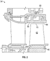
- the high pressure turbine 54 includes one high pressure turbine rotors 60 having a plurality of turbine rotor blades 62.
- the high pressure turbine rotors 60 are configured to have a clearance gap 64 between a blade tip 70 and a blade outer airseal 66 secured to a rotationally fixed structure, for example, a high pressure turbine case 68, located radially outboard of the blade tip 70. It is desired to maintain as small a clearance gap 64 as possible throughout the engine 20 operating envelope, without the blade tips 70 contacting the blade outer airseal 66, a condition known as a "rub" .
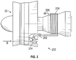
- the engine 20 includes an Active Clearance Control (ACC) system 200 to control the clearance gaps 64 between the blade tips 70 and the blade outer airseal 66.
- the ACC system 200 includes a valve 202, which in some embodiments is an electronically commanded, hydraulically actuated butterfly valve that directs airflow 204 from the turbofan bypass stream B to an outer circumference 206 of the high pressure turbine case 68 via one of more flow passages 208 extending around the outer circumference 206.
- the heat transfer effects of the relatively cool bypass airflow 204 convecting over the relatively hot high pressure turbine case 68 forces the case 68 to close in on the blade tips 70 (shown best in FIG.
- the high pressure compressor 52 includes one or more high pressure compressor stators 72 and one or more high pressure compressor rotors 74 (shown in FIG. 1 ).
- One or more of the HPC stators 72 are variable pitch stators.
- the high pressure compressor stators 72 include a plurality of stator vanes 76, which are selectably rotatable about their respective stator axes 78 by an actuation system 80.
- the stator vanes 76 are movable by the actuation system 80 between an "open" position and a "closed” position.
- a fuel flow rate to the combustor section 26 is modulated via biasing one of the limits that the on-board constrained model-based multivariable control respects. Reduction of the fuel flow rate reduces the N1 acceleration rate. Such fuel flow modulation abates the N1 acceleration rate in order to preserve a nominal response and reduce a turbine clearance rub risk in the Low-Pressure Turbine (LPT) 46 from the analogous problem of centrifugal blade growth.
- LPT Low-Pressure Turbine
- a butterfly valve directs air from the turbofan bypass stream B to the outer circumference of the high pressure turbine case 68.
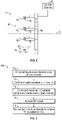
- an engine control system 90 commands a rapid or "snap" acceleration of the engine 20, causing acceleration of the high pressure turbine rotor 60.
- the engine control system commands movement of the variable high pressure compressor stator vanes 76 toward the open position, thereby reducing an acceleration rate of the high pressure turbine rotor 60. The reduction of the acceleration rate reduces the risk of a rub between the blade tips 70 and the blade outer airseal 66.
- the acceleration rate of N1 increases.
- a fuel flow to the combustor 26 is modulated to reduce an N1 acceleration rate.
- the clearance gap 64 to which the engine 20 control to set to achieve is determined based on the smallest cruise, steady-state clearance gap 64 that would not permit a rub given an aggressive command engine acceleration. With the use of this new control mode, the clearance pinch during that acceleration is less in magnitude. This directly allows the entire steady-state target to be lower by the amount by which the pinch was reduced. Said differently, there is a current sub-optimal steady-state clearance that is held for a majority of a typical commercial mission as a precaution for a potential sharp increase in engine power while at cruise that may not occur.
- the benefit that is accrued is over the duration of the cruise segment of a typical mission being that clearances can be run more closely to optimal levels. As mentioned, the tighter the clearances can be held, the benefits can be felt in fuel burn and hot section refurbishment interval.
Landscapes
- Engineering & Computer Science (AREA)
- Chemical & Material Sciences (AREA)
- Combustion & Propulsion (AREA)
- Mechanical Engineering (AREA)
- General Engineering & Computer Science (AREA)
- Physics & Mathematics (AREA)
- Fluid Mechanics (AREA)
- Turbine Rotor Nozzle Sealing (AREA)
- Structures Of Non-Positive Displacement Pumps (AREA)
Claims (8)
- Verfahren zum Betreiben eines Gasturbinentriebwerks (20), umfassend:Befehlen (104) einer Beschleunigung des Gasturbinentriebwerks; Bewegen (106) einer Hochdruckkompressorschaufel (76) mit variabler Steigung in Richtung einer offenen Position, wodurch eine Beschleunigungsrate eines Hochdruckturbinenrotors (60) reduziert wird, wodurch eine Änderung in einem Spielspalt (64) zwischen dem Hochdruckturbinenrotor und einer äußeren Schaufelluftdichtung (66) reduziert wird; undLeiten (102) eines Teils eines Turbolüfter-Nebenstroms (B) zu einem Außenumfang (206) eines Turbinengehäuses (68), um ein thermisches Wachstum eines Turbinengehäuses zu steuern, in dem die äußere Schaufelluftdichtung (66) angeordnet ist;wobei das Verfahren gekennzeichnet ist durch:Erhöhen (108) einer Drehzahl einer Niederdruckturbine (46) in Reaktion auf die Verlangsamung der Beschleunigungsrate des Hochdruckturbinenrotors (60); undModulieren (110) einer Kraftstoffströmung zu einer Brennkammer (26) des Gasturbinentriebwerks (20), um eine Beschleunigungsrate der Niederdruckturbine zu reduzieren.
- Verfahren nach Anspruch 1, wobei das Modulieren (110) der Kraftstoffströmung eine Reduzieren einer Rate der Kraftstoffströmung ist.
- Verfahren nach Anspruch 1 oder 2, wobei das Reduzieren der Beschleunigungsrate eines Hochdruckturbinenrotors (60) einen Reibungszustand zwischen der äußeren Schaufelluftdichtung (66) und dem Hochdruckturbinenrotor während der Beschleunigung des Gasturbinentriebwerks (20) verhindert.
- Gasturbinentriebwerk (20), umfassend:
einen Turbinenabschnitt (28) beinhaltend:einen Hochdruckturbinenrotor (60) mit einer Vielzahl von Rotorschaufeln (62);eine Niederdruckturbine (46), die stromabwärts der Hochdruckturbine (54) angeordnet ist; undeine äußere Schaufelluftdichtung (66), die radial außerhalb des Hochdruckturbinenrotors angeordnet ist und einen radialen Spielspalt (64) zwischen der Vielzahl von Rotorschaufeln und der äußeren Schaufelluftdichtung definiert;eine Brennkammer (26), die stromaufwärts der Hochdruckturbine angeordnet ist;einen Kompressorabschnitt (24), beinhaltend:einen Hochdruckkompressorrotor (74), der betriebsmäßig über eine äußere Welle (50) mit der Hochdruckturbine verbunden ist;einen Hochdruckkompressorstator (72), der eine Vielzahl von Statorschaufeln (76) mit variabler Steigung beinhaltet;wobei die Niederdruckturbine (46) an einer inneren Welle (40) getrennt von der äußeren Welle (50) befestigt ist;ein Betätigungssystem (80), das betriebsmäßig mit der Vielzahl von Statorschaufeln mit variabler Steigung verbunden ist und so konfiguriert ist, dass es die Statorschaufeln mit variabler Steigung zwischen einer geschlossenen Position und einer offenen Position bewegt; undein Triebwerksteuersystem (90), konfiguriert zum:Befehlen (104) einer Beschleunigung des Gasturbinentriebwerks; undBewegen (106) einer Hochdruckkompressorschaufel (76) mit variabler Steigung in Richtung einer offenen Position, wodurch eine Beschleunigungsrate eines Hochdruckturbinenrotors verlangsamt wird, wodurch eine Änderung in einem Spielspalt (64) zwischen dem Hochdruckturbinenrotor und einer äußeren Schaufelluftdichtung reduziert wird;wobei das Triebwerksystem (90) zusätzlich so konfiguriert ist, dass es eine Kraftstoffströmung zu der Brennkammer in Reaktion auf die Verlangsamung der Beschleunigungsrate des Hochdruckturbinenrotors moduliert, wodurch eine Beschleunigungsrate der Niederdruckturbine reduziert wird. - Gasturbinentriebwerk (20) nach Anspruch 4, wobei das Modulieren der Kraftstoffströmung ein Reduzieren einer Rate der Brennstoffströmung ist.
- Gasturbinentriebwerk (20) nach Anspruch 4 oder 5, wobei die äußere Schaufelluftdichtung (66) in einem Hochdruckturbinengehäuse (68) angeordnet ist.
- Gasturbinentriebwerk (20) nach einem der Ansprüche 4 bis 6, wobei die Reduzierung der Beschleunigungsrate eines Hochdruckturbinenrotors (60) einen Reibungszustand zwischen der äußeren Schaufelluftdichtung (66) und dem Hochdruckturbinenrotor während der Beschleunigung des Gasturbinentriebwerks verhindert.
- Gasturbinentriebwerk (20) nach einem der Ansprüche 4 bis 7, wobei die Vielzahl von Statorschaufeln (76) mit variabler Steigung um eine Schaufelachse drehbar ist, um sich zwischen der offenen Position und der geschlossenen Position zu bewegen.
Applications Claiming Priority (1)
| Application Number | Priority Date | Filing Date | Title |
|---|---|---|---|
| US16/388,227 US11473510B2 (en) | 2019-04-18 | 2019-04-18 | Active multi-effector control of high pressure turbine clearances |
Publications (2)
| Publication Number | Publication Date |
|---|---|
| EP3726010A1 EP3726010A1 (de) | 2020-10-21 |
| EP3726010B1 true EP3726010B1 (de) | 2022-12-07 |
Family
ID=70292759
Family Applications (1)
| Application Number | Title | Priority Date | Filing Date |
|---|---|---|---|
| EP20169684.6A Active EP3726010B1 (de) | 2019-04-18 | 2020-04-15 | Aktive multieffektorspaltsteuerung in hochdruckturbinen |
Country Status (2)
| Country | Link |
|---|---|
| US (1) | US11473510B2 (de) |
| EP (1) | EP3726010B1 (de) |
Families Citing this family (5)
| Publication number | Priority date | Publication date | Assignee | Title |
|---|---|---|---|---|
| CN112431639A (zh) * | 2020-11-27 | 2021-03-02 | 北京化工大学 | 一种可抑制非均匀多尺度燃气入侵的轮缘密封结构 |
| CN113250759A (zh) * | 2021-04-30 | 2021-08-13 | 上海慕帆动力科技有限公司 | 一种trt间隙调节系统 |
| US12410758B2 (en) | 2022-01-10 | 2025-09-09 | General Electric Company | Three-stream gas turbine engine control |
| US11933232B1 (en) | 2023-02-21 | 2024-03-19 | General Electric Company | Hybrid-electric gas turbine engine and method of operating |
| US12313012B2 (en) | 2023-08-14 | 2025-05-27 | General Electric Company | System and method for reducing a clearance gap in an engine |
Family Cites Families (19)
| Publication number | Priority date | Publication date | Assignee | Title |
|---|---|---|---|---|
| US4257222A (en) | 1977-12-21 | 1981-03-24 | United Technologies Corporation | Seal clearance control system for a gas turbine |
| US4304093A (en) | 1979-08-31 | 1981-12-08 | General Electric Company | Variable clearance control for a gas turbine engine |
| DE3606597C1 (de) | 1986-02-28 | 1987-02-19 | Mtu Muenchen Gmbh | Schaufel- und Dichtspaltoptimierungseinrichtung fuer Verdichter von Gasturbinentriebwerken |
| US5165845A (en) | 1991-11-08 | 1992-11-24 | United Technologies Corporation | Controlling stall margin in a gas turbine engine during acceleration |
| US5165844A (en) | 1991-11-08 | 1992-11-24 | United Technologies Corporation | On-line stall margin adjustment in a gas turbine engine |
| US6164902A (en) | 1998-12-11 | 2000-12-26 | United Technologies Corporation | Controlling stall margin in a gas turbine engine during acceleration |
| US6272422B2 (en) | 1998-12-23 | 2001-08-07 | United Technologies Corporation | Method and apparatus for use in control of clearances in a gas turbine engine |
| US6155038A (en) | 1998-12-23 | 2000-12-05 | United Technologies Corporation | Method and apparatus for use in control and compensation of clearances in a gas turbine |
| US6735955B2 (en) | 2001-10-10 | 2004-05-18 | Goodrich Pump & Engine Control Systems, Inc. | Control system for positioning compressor inlet guide vanes |
| US8011883B2 (en) | 2004-12-29 | 2011-09-06 | United Technologies Corporation | Gas turbine engine blade tip clearance apparatus and method |
| US7866159B2 (en) * | 2005-10-18 | 2011-01-11 | Rolls-Royce Corporation | Variable geometry hysteresis control for a gas turbine engine |
| US7597537B2 (en) * | 2005-12-16 | 2009-10-06 | General Electric Company | Thermal control of gas turbine engine rings for active clearance control |
| US20090096174A1 (en) * | 2007-02-28 | 2009-04-16 | United Technologies Corporation | Blade outer air seal for a gas turbine engine |
| US8126628B2 (en) | 2007-08-03 | 2012-02-28 | General Electric Company | Aircraft gas turbine engine blade tip clearance control |
| US9260974B2 (en) | 2011-12-16 | 2016-02-16 | General Electric Company | System and method for active clearance control |
| US9097133B2 (en) | 2012-06-04 | 2015-08-04 | United Technologies Corporation | Compressor tip clearance management for a gas turbine engine |
| US9758252B2 (en) | 2012-08-23 | 2017-09-12 | General Electric Company | Method, system, and apparatus for reducing a turbine clearance |
| EP2972604B1 (de) | 2013-03-15 | 2020-04-29 | United Technologies Corporation | Auf einem kompakten luft-wärme-modell basierender startalgorithmus für ein regelungssystem |
| US10794213B2 (en) | 2016-06-21 | 2020-10-06 | Rolls-Royce North American Technologies Inc. | Blade tip clearance control for an axial compressor with radially outer annulus |
-
2019
- 2019-04-18 US US16/388,227 patent/US11473510B2/en active Active
-
2020
- 2020-04-15 EP EP20169684.6A patent/EP3726010B1/de active Active
Also Published As
| Publication number | Publication date |
|---|---|
| US20200332726A1 (en) | 2020-10-22 |
| EP3726010A1 (de) | 2020-10-21 |
| US11473510B2 (en) | 2022-10-18 |
Similar Documents
| Publication | Publication Date | Title |
|---|---|---|
| US11473510B2 (en) | Active multi-effector control of high pressure turbine clearances | |
| US11378009B2 (en) | Multi-mode heat rejection system for a gas turbine engine | |
| US11092030B2 (en) | Adaptive case for a gas turbine engine | |
| US10815819B2 (en) | Variable area turbine arrangement with secondary flow modulation | |
| EP1775424B1 (de) | Vorrichtung sowie Verfahren zur Regelung des Schaufelspitzenspiels in einer Gasturbine | |
| EP2980361B1 (de) | Kühlsystem einer statoranordnung für einen gasturbinenmotor mit variablem kühlflussmechanismus und verfahren zum betrieb | |
| EP3358144A1 (de) | Schubleistungsabhängiges aktives spitzenspaltkontrollsystem | |
| EP3789588B1 (de) | Hydrostatische dichtung ausgerichtet mit der rotordrehrichtung | |
| EP3789589B1 (de) | Hydrostatische dichtung | |
| US20180334965A1 (en) | Bleed flow safety system | |
| EP3536903B1 (de) | Kühlkanal mit strukturrippe und filmkühlschlitz | |
| EP3406882B1 (de) | Aktive zapfströmungsmodulation | |
| US9995217B2 (en) | Rotary valve for bleed flow path | |
| EP3165717B1 (de) | Verdichterausgangsdichtung | |
| EP3428408A1 (de) | Einsatzelement am ende einer verstellbaren schaufel in einem gasturbinentriebwerk | |
| EP3623585B1 (de) | Druckseitige abdeckung einer leitschaufelanordnung mit variabler krümmung für den verdichter eines gasturbinentriebwerks | |
| EP3772570A1 (de) | Hydrostatische dichtung mit verlängertem trägerarm | |
| US10612407B2 (en) | Contoured blade outer air seal for a gas turbine engine | |
| EP3623587B1 (de) | Schaufelprofilanordnug für ein gasturbinentriebwerk | |
| EP2995778B1 (de) | Verfahren und anordnung zur verminderung sekundärer wärme in einem gasturbinenmotor | |
| EP3470656B1 (de) | Modulierter brennkammer-bypass | |
| US10472981B2 (en) | Edge treatment for gas turbine engine component | |
| EP3508790B1 (de) | Gasturbinenmotor mit einem modulierten brennkammer-bypass und einem brennkammer-bypassventil | |
| EP4372208A1 (de) | Dichtung für gasturbinenmotor |
Legal Events
| Date | Code | Title | Description |
|---|---|---|---|
| PUAI | Public reference made under article 153(3) epc to a published international application that has entered the european phase |
Free format text: ORIGINAL CODE: 0009012 |
|
| STAA | Information on the status of an ep patent application or granted ep patent |
Free format text: STATUS: THE APPLICATION HAS BEEN PUBLISHED |
|
| AK | Designated contracting states |
Kind code of ref document: A1 Designated state(s): AL AT BE BG CH CY CZ DE DK EE ES FI FR GB GR HR HU IE IS IT LI LT LU LV MC MK MT NL NO PL PT RO RS SE SI SK SM TR |
|
| AX | Request for extension of the european patent |
Extension state: BA ME |
|
| STAA | Information on the status of an ep patent application or granted ep patent |
Free format text: STATUS: REQUEST FOR EXAMINATION WAS MADE |
|
| 17P | Request for examination filed |
Effective date: 20210421 |
|
| RBV | Designated contracting states (corrected) |
Designated state(s): AL AT BE BG CH CY CZ DE DK EE ES FI FR GB GR HR HU IE IS IT LI LT LU LV MC MK MT NL NO PL PT RO RS SE SI SK SM TR |
|
| RIC1 | Information provided on ipc code assigned before grant |
Ipc: F02K 3/075 20060101ALN20220420BHEP Ipc: F02C 9/54 20060101ALI20220420BHEP Ipc: F02C 9/20 20060101ALI20220420BHEP Ipc: F02C 6/06 20060101ALI20220420BHEP Ipc: F01D 11/24 20060101ALI20220420BHEP Ipc: F01D 11/14 20060101AFI20220420BHEP |
|
| GRAP | Despatch of communication of intention to grant a patent |
Free format text: ORIGINAL CODE: EPIDOSNIGR1 |
|
| STAA | Information on the status of an ep patent application or granted ep patent |
Free format text: STATUS: GRANT OF PATENT IS INTENDED |
|
| INTG | Intention to grant announced |
Effective date: 20220622 |
|
| GRAS | Grant fee paid |
Free format text: ORIGINAL CODE: EPIDOSNIGR3 |
|
| GRAA | (expected) grant |
Free format text: ORIGINAL CODE: 0009210 |
|
| STAA | Information on the status of an ep patent application or granted ep patent |
Free format text: STATUS: THE PATENT HAS BEEN GRANTED |
|
| AK | Designated contracting states |
Kind code of ref document: B1 Designated state(s): AL AT BE BG CH CY CZ DE DK EE ES FI FR GB GR HR HU IE IS IT LI LT LU LV MC MK MT NL NO PL PT RO RS SE SI SK SM TR |
|
| REG | Reference to a national code |
Ref country code: GB Ref legal event code: FG4D |
|
| REG | Reference to a national code |
Ref country code: CH Ref legal event code: EP Ref country code: AT Ref legal event code: REF Ref document number: 1536433 Country of ref document: AT Kind code of ref document: T Effective date: 20221215 |
|
| REG | Reference to a national code |
Ref country code: DE Ref legal event code: R096 Ref document number: 602020006713 Country of ref document: DE |
|
| REG | Reference to a national code |
Ref country code: IE Ref legal event code: FG4D |
|
| REG | Reference to a national code |
Ref country code: LT Ref legal event code: MG9D |
|
| REG | Reference to a national code |
Ref country code: NL Ref legal event code: MP Effective date: 20221207 |
|
| PG25 | Lapsed in a contracting state [announced via postgrant information from national office to epo] |
Ref country code: SE Free format text: LAPSE BECAUSE OF FAILURE TO SUBMIT A TRANSLATION OF THE DESCRIPTION OR TO PAY THE FEE WITHIN THE PRESCRIBED TIME-LIMIT Effective date: 20221207 Ref country code: NO Free format text: LAPSE BECAUSE OF FAILURE TO SUBMIT A TRANSLATION OF THE DESCRIPTION OR TO PAY THE FEE WITHIN THE PRESCRIBED TIME-LIMIT Effective date: 20230307 Ref country code: LT Free format text: LAPSE BECAUSE OF FAILURE TO SUBMIT A TRANSLATION OF THE DESCRIPTION OR TO PAY THE FEE WITHIN THE PRESCRIBED TIME-LIMIT Effective date: 20221207 Ref country code: FI Free format text: LAPSE BECAUSE OF FAILURE TO SUBMIT A TRANSLATION OF THE DESCRIPTION OR TO PAY THE FEE WITHIN THE PRESCRIBED TIME-LIMIT Effective date: 20221207 Ref country code: ES Free format text: LAPSE BECAUSE OF FAILURE TO SUBMIT A TRANSLATION OF THE DESCRIPTION OR TO PAY THE FEE WITHIN THE PRESCRIBED TIME-LIMIT Effective date: 20221207 |
|
| REG | Reference to a national code |
Ref country code: AT Ref legal event code: MK05 Ref document number: 1536433 Country of ref document: AT Kind code of ref document: T Effective date: 20221207 |
|
| PG25 | Lapsed in a contracting state [announced via postgrant information from national office to epo] |
Ref country code: RS Free format text: LAPSE BECAUSE OF FAILURE TO SUBMIT A TRANSLATION OF THE DESCRIPTION OR TO PAY THE FEE WITHIN THE PRESCRIBED TIME-LIMIT Effective date: 20221207 Ref country code: PL Free format text: LAPSE BECAUSE OF FAILURE TO SUBMIT A TRANSLATION OF THE DESCRIPTION OR TO PAY THE FEE WITHIN THE PRESCRIBED TIME-LIMIT Effective date: 20221207 Ref country code: LV Free format text: LAPSE BECAUSE OF FAILURE TO SUBMIT A TRANSLATION OF THE DESCRIPTION OR TO PAY THE FEE WITHIN THE PRESCRIBED TIME-LIMIT Effective date: 20221207 Ref country code: HR Free format text: LAPSE BECAUSE OF FAILURE TO SUBMIT A TRANSLATION OF THE DESCRIPTION OR TO PAY THE FEE WITHIN THE PRESCRIBED TIME-LIMIT Effective date: 20221207 Ref country code: GR Free format text: LAPSE BECAUSE OF FAILURE TO SUBMIT A TRANSLATION OF THE DESCRIPTION OR TO PAY THE FEE WITHIN THE PRESCRIBED TIME-LIMIT Effective date: 20230308 |
|
| P01 | Opt-out of the competence of the unified patent court (upc) registered |
Effective date: 20230521 |
|
| PG25 | Lapsed in a contracting state [announced via postgrant information from national office to epo] |
Ref country code: NL Free format text: LAPSE BECAUSE OF FAILURE TO SUBMIT A TRANSLATION OF THE DESCRIPTION OR TO PAY THE FEE WITHIN THE PRESCRIBED TIME-LIMIT Effective date: 20221207 |
|
| PG25 | Lapsed in a contracting state [announced via postgrant information from national office to epo] |
Ref country code: SM Free format text: LAPSE BECAUSE OF FAILURE TO SUBMIT A TRANSLATION OF THE DESCRIPTION OR TO PAY THE FEE WITHIN THE PRESCRIBED TIME-LIMIT Effective date: 20221207 Ref country code: RO Free format text: LAPSE BECAUSE OF FAILURE TO SUBMIT A TRANSLATION OF THE DESCRIPTION OR TO PAY THE FEE WITHIN THE PRESCRIBED TIME-LIMIT Effective date: 20221207 Ref country code: PT Free format text: LAPSE BECAUSE OF FAILURE TO SUBMIT A TRANSLATION OF THE DESCRIPTION OR TO PAY THE FEE WITHIN THE PRESCRIBED TIME-LIMIT Effective date: 20230410 Ref country code: EE Free format text: LAPSE BECAUSE OF FAILURE TO SUBMIT A TRANSLATION OF THE DESCRIPTION OR TO PAY THE FEE WITHIN THE PRESCRIBED TIME-LIMIT Effective date: 20221207 Ref country code: CZ Free format text: LAPSE BECAUSE OF FAILURE TO SUBMIT A TRANSLATION OF THE DESCRIPTION OR TO PAY THE FEE WITHIN THE PRESCRIBED TIME-LIMIT Effective date: 20221207 Ref country code: AT Free format text: LAPSE BECAUSE OF FAILURE TO SUBMIT A TRANSLATION OF THE DESCRIPTION OR TO PAY THE FEE WITHIN THE PRESCRIBED TIME-LIMIT Effective date: 20221207 |
|
| PG25 | Lapsed in a contracting state [announced via postgrant information from national office to epo] |
Ref country code: SK Free format text: LAPSE BECAUSE OF FAILURE TO SUBMIT A TRANSLATION OF THE DESCRIPTION OR TO PAY THE FEE WITHIN THE PRESCRIBED TIME-LIMIT Effective date: 20221207 Ref country code: IS Free format text: LAPSE BECAUSE OF FAILURE TO SUBMIT A TRANSLATION OF THE DESCRIPTION OR TO PAY THE FEE WITHIN THE PRESCRIBED TIME-LIMIT Effective date: 20230407 Ref country code: AL Free format text: LAPSE BECAUSE OF FAILURE TO SUBMIT A TRANSLATION OF THE DESCRIPTION OR TO PAY THE FEE WITHIN THE PRESCRIBED TIME-LIMIT Effective date: 20221207 |
|
| REG | Reference to a national code |
Ref country code: DE Ref legal event code: R097 Ref document number: 602020006713 Country of ref document: DE |
|
| PLBE | No opposition filed within time limit |
Free format text: ORIGINAL CODE: 0009261 |
|
| STAA | Information on the status of an ep patent application or granted ep patent |
Free format text: STATUS: NO OPPOSITION FILED WITHIN TIME LIMIT |
|
| PG25 | Lapsed in a contracting state [announced via postgrant information from national office to epo] |
Ref country code: DK Free format text: LAPSE BECAUSE OF FAILURE TO SUBMIT A TRANSLATION OF THE DESCRIPTION OR TO PAY THE FEE WITHIN THE PRESCRIBED TIME-LIMIT Effective date: 20221207 |
|
| RAP4 | Party data changed (patent owner data changed or rights of a patent transferred) |
Owner name: RTX CORPORATION |
|
| 26N | No opposition filed |
Effective date: 20230908 |
|
| PG25 | Lapsed in a contracting state [announced via postgrant information from national office to epo] |
Ref country code: SI Free format text: LAPSE BECAUSE OF FAILURE TO SUBMIT A TRANSLATION OF THE DESCRIPTION OR TO PAY THE FEE WITHIN THE PRESCRIBED TIME-LIMIT Effective date: 20221207 |
|
| REG | Reference to a national code |
Ref country code: CH Ref legal event code: PL |
|
| PG25 | Lapsed in a contracting state [announced via postgrant information from national office to epo] |
Ref country code: LU Free format text: LAPSE BECAUSE OF NON-PAYMENT OF DUE FEES Effective date: 20230415 |
|
| REG | Reference to a national code |
Ref country code: BE Ref legal event code: MM Effective date: 20230430 |
|
| PG25 | Lapsed in a contracting state [announced via postgrant information from national office to epo] |
Ref country code: MC Free format text: LAPSE BECAUSE OF FAILURE TO SUBMIT A TRANSLATION OF THE DESCRIPTION OR TO PAY THE FEE WITHIN THE PRESCRIBED TIME-LIMIT Effective date: 20221207 |
|
| PG25 | Lapsed in a contracting state [announced via postgrant information from national office to epo] |
Ref country code: MC Free format text: LAPSE BECAUSE OF FAILURE TO SUBMIT A TRANSLATION OF THE DESCRIPTION OR TO PAY THE FEE WITHIN THE PRESCRIBED TIME-LIMIT Effective date: 20221207 Ref country code: LI Free format text: LAPSE BECAUSE OF NON-PAYMENT OF DUE FEES Effective date: 20230430 Ref country code: CH Free format text: LAPSE BECAUSE OF NON-PAYMENT OF DUE FEES Effective date: 20230430 |
|
| REG | Reference to a national code |
Ref country code: IE Ref legal event code: MM4A |
|
| PG25 | Lapsed in a contracting state [announced via postgrant information from national office to epo] |
Ref country code: BE Free format text: LAPSE BECAUSE OF NON-PAYMENT OF DUE FEES Effective date: 20230430 |
|
| PG25 | Lapsed in a contracting state [announced via postgrant information from national office to epo] |
Ref country code: IE Free format text: LAPSE BECAUSE OF NON-PAYMENT OF DUE FEES Effective date: 20230415 |
|
| PG25 | Lapsed in a contracting state [announced via postgrant information from national office to epo] |
Ref country code: IE Free format text: LAPSE BECAUSE OF NON-PAYMENT OF DUE FEES Effective date: 20230415 |
|
| PG25 | Lapsed in a contracting state [announced via postgrant information from national office to epo] |
Ref country code: IT Free format text: LAPSE BECAUSE OF FAILURE TO SUBMIT A TRANSLATION OF THE DESCRIPTION OR TO PAY THE FEE WITHIN THE PRESCRIBED TIME-LIMIT Effective date: 20221207 |
|
| PG25 | Lapsed in a contracting state [announced via postgrant information from national office to epo] |
Ref country code: BG Free format text: LAPSE BECAUSE OF FAILURE TO SUBMIT A TRANSLATION OF THE DESCRIPTION OR TO PAY THE FEE WITHIN THE PRESCRIBED TIME-LIMIT Effective date: 20221207 |
|
| PG25 | Lapsed in a contracting state [announced via postgrant information from national office to epo] |
Ref country code: BG Free format text: LAPSE BECAUSE OF FAILURE TO SUBMIT A TRANSLATION OF THE DESCRIPTION OR TO PAY THE FEE WITHIN THE PRESCRIBED TIME-LIMIT Effective date: 20221207 |
|
| PGFP | Annual fee paid to national office [announced via postgrant information from national office to epo] |
Ref country code: DE Payment date: 20250319 Year of fee payment: 6 |
|
| PG25 | Lapsed in a contracting state [announced via postgrant information from national office to epo] |
Ref country code: CY Free format text: LAPSE BECAUSE OF FAILURE TO SUBMIT A TRANSLATION OF THE DESCRIPTION OR TO PAY THE FEE WITHIN THE PRESCRIBED TIME-LIMIT; INVALID AB INITIO Effective date: 20200415 |
|
| PG25 | Lapsed in a contracting state [announced via postgrant information from national office to epo] |
Ref country code: HU Free format text: LAPSE BECAUSE OF FAILURE TO SUBMIT A TRANSLATION OF THE DESCRIPTION OR TO PAY THE FEE WITHIN THE PRESCRIBED TIME-LIMIT; INVALID AB INITIO Effective date: 20200415 |
|
| REG | Reference to a national code |
Ref country code: DE Ref legal event code: R081 Ref document number: 602020006713 Country of ref document: DE Owner name: RTX CORPORATION (N.D.GES.D. STAATES DELAWARE),, US Free format text: FORMER OWNER: RAYTHEON TECHNOLOGIES CORPORATION, FARMINGTON, CT, US |
|
| PG25 | Lapsed in a contracting state [announced via postgrant information from national office to epo] |
Ref country code: TR Free format text: LAPSE BECAUSE OF FAILURE TO SUBMIT A TRANSLATION OF THE DESCRIPTION OR TO PAY THE FEE WITHIN THE PRESCRIBED TIME-LIMIT Effective date: 20221207 |
|
| PGFP | Annual fee paid to national office [announced via postgrant information from national office to epo] |
Ref country code: GB Payment date: 20260319 Year of fee payment: 7 |
|
| PGFP | Annual fee paid to national office [announced via postgrant information from national office to epo] |
Ref country code: FR Payment date: 20260320 Year of fee payment: 7 |