EP3727760B1 - Eintreibvorrichtung - Google Patents
Eintreibvorrichtung Download PDFInfo
- Publication number
- EP3727760B1 EP3727760B1 EP18808401.6A EP18808401A EP3727760B1 EP 3727760 B1 EP3727760 B1 EP 3727760B1 EP 18808401 A EP18808401 A EP 18808401A EP 3727760 B1 EP3727760 B1 EP 3727760B1
- Authority
- EP
- European Patent Office
- Prior art keywords
- driving
- housing
- gravity
- energy
- guide
- Prior art date
- Legal status (The legal status is an assumption and is not a legal conclusion. Google has not performed a legal analysis and makes no representation as to the accuracy of the status listed.)
- Active
Links
Images

Classifications
-
- B—PERFORMING OPERATIONS; TRANSPORTING
- B25—HAND TOOLS; PORTABLE POWER-DRIVEN TOOLS; MANIPULATORS
- B25C—HAND-HELD NAILING OR STAPLING TOOLS; MANUALLY OPERATED PORTABLE STAPLING TOOLS
- B25C1/00—Hand-held nailing tools; Nail feeding devices
- B25C1/001—Nail feeding devices
- B25C1/005—Nail feeding devices for rows of contiguous nails
-
- B—PERFORMING OPERATIONS; TRANSPORTING
- B25—HAND TOOLS; PORTABLE POWER-DRIVEN TOOLS; MANIPULATORS
- B25C—HAND-HELD NAILING OR STAPLING TOOLS; MANUALLY OPERATED PORTABLE STAPLING TOOLS
- B25C1/00—Hand-held nailing tools; Nail feeding devices
-
- B—PERFORMING OPERATIONS; TRANSPORTING
- B25—HAND TOOLS; PORTABLE POWER-DRIVEN TOOLS; MANIPULATORS
- B25C—HAND-HELD NAILING OR STAPLING TOOLS; MANUALLY OPERATED PORTABLE STAPLING TOOLS
- B25C1/00—Hand-held nailing tools; Nail feeding devices
- B25C1/06—Hand-held nailing tools; Nail feeding devices operated by electric power
-
- B—PERFORMING OPERATIONS; TRANSPORTING
- B25—HAND TOOLS; PORTABLE POWER-DRIVEN TOOLS; MANIPULATORS
- B25C—HAND-HELD NAILING OR STAPLING TOOLS; MANUALLY OPERATED PORTABLE STAPLING TOOLS
- B25C1/00—Hand-held nailing tools; Nail feeding devices
- B25C1/08—Hand-held nailing tools; Nail feeding devices operated by combustion pressure
- B25C1/10—Hand-held nailing tools; Nail feeding devices operated by combustion pressure generated by detonation of a cartridge
- B25C1/18—Details and accessories, e.g. splinter guards, spall minimisers
- B25C1/188—Arrangements at the forward end of the barrel, e.g. splinter guards, spall minimisers, safety arrangements, silencers, bolt retainers
-
- B—PERFORMING OPERATIONS; TRANSPORTING
- B25—HAND TOOLS; PORTABLE POWER-DRIVEN TOOLS; MANIPULATORS
- B25F—COMBINATION OR MULTI-PURPOSE TOOLS NOT OTHERWISE PROVIDED FOR; DETAILS OR COMPONENTS OF PORTABLE POWER-DRIVEN TOOLS NOT PARTICULARLY RELATED TO THE OPERATIONS PERFORMED AND NOT OTHERWISE PROVIDED FOR
- B25F5/00—Details or components of portable power-driven tools not particularly related to the operations performed and not otherwise provided for
- B25F5/02—Construction of casings, bodies or handles
-
- F—MECHANICAL ENGINEERING; LIGHTING; HEATING; WEAPONS; BLASTING
- F41—WEAPONS
- F41A—FUNCTIONAL FEATURES OR DETAILS COMMON TO BOTH SMALLARMS AND ORDNANCE, e.g. CANNONS; MOUNTINGS FOR SMALLARMS OR ORDNANCE
- F41A17/00—Safety arrangements, e.g. safeties
- F41A17/34—Magazine safeties
- F41A17/38—Magazine mountings, e.g. for locking the magazine in the gun
Definitions
- the application relates to a device for driving a fastener into a substrate.
- Such devices usually have a piston for transmitting energy to the fastener.
- the energy required for this must be made available in a very short time, which is why, for example, in the case of so-called spring nailers, a spring is first tensioned, which abruptly transfers the tensioning energy to the piston during the driving process and accelerates it towards the fastening element.
- the abruptly released energy, with which the fastener is driven into the ground causes a recoil, which mechanically stresses some components of such devices.
- the recoil involves a torque that tilts the entire device as the fastener is driven into the ground.
- a device for driving a fastener into a substrate according to the preamble of claim 1 in which fasteners driven by a drive element are guided in a fastener channel.
- a spring in the fastener channel deflects the fastener but not the driver during a fastening operation.
- the drive element should remain aligned towards the fastener after the fastening tool has been tilted.
- a drill/driver is known with a working component comprising a first chuck for a drill and a second chuck for a screw drive.
- the first chuck transmits torque to a drill mounted therein
- the second chuck transmits torque to a screw driver mounted therein.
- a control mechanism locates the working component in the first or second position.
- the object of the invention is to improve the fastening quality of the device mentioned at the outset.
- the object is achieved with a device for driving a fastener into a substrate, having a center of gravity, an energy transmission element that can be moved between an initial position and a setting position for transmitting driving energy to the fastener, a piston drive that provides the driving energy, a housing and a Driving guide bolt guide, wherein the bolt guide is rotatably mounted on the housing with respect to rotation about the center of gravity.
- the bolt guide has a holder which is mounted on the housing such that it can rotate about the center of gravity and can rotate with respect to rotation and includes a deceleration element for braking the energy transmission element. Due to the rotatable mounting, the bolt guide remains in its position due to its mass inertia even if the rest of the device is already tilting due to the recoil. This applies to the period in which the fastener is driven into the ground.
- An advantageous embodiment is characterized in that the device has a damping element which dampens a rotary movement of the bolt guide about the center of gravity.
- An advantageous embodiment is characterized in that the bolt guide is rotatably mounted on the housing along an angular range of at least 2°.
- the angular range preferably extends over at least 3°, particularly preferably over at least 5°.
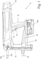
- the driving-in device 10 for driving a fastener, such as a nail or bolt, into a substrate in a side view.
- the driving-in device 10 has an energy transmission element, not shown, for transmitting energy to the fastening element, and a housing 20, in which the energy transmission element and a drive device, also not shown, for conveying the energy transmission element are accommodated.
- the driving device 10 also has a handle 30 , a magazine 40 and a bridge 50 connecting the handle 30 to the magazine 40 .
- the magazine is not removable.
- a scaffolding hook 60 for suspending the driving-in device 10 on a scaffolding or the like and an electrical energy store designed as a rechargeable battery 590 are fastened to the bridge 50 .
- a trigger 34 and a grip sensor designed as a manual switch 35 are arranged on the grip 30 .
- the driving-in device 10 has a guide channel 700 for guiding the fastening element and a pressing device 750 for detecting a distance of the driving-in device 10 from a substrate (not shown). Alignment of the driving-in device perpendicular to a substrate is supported by an alignment aid 45 .
- Drive device 70 comprises an electric motor, not shown, for converting electrical energy from battery 590 into rotational energy, a torque transmission device comprising a gearbox 400 for transmitting a torque of the electric motor to a motion converter embodied as a spindle drive 300, a power transmission device comprising a roller train 260 for transmitting a force from the movement converter to a mechanical energy store designed as a spring 200 and for transmitting a force from the spring to the energy transmission element.
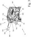
- the driving device 10 in an oblique view with the housing 20 open.
- the front roller holder 281 can be seen in the housing.
- the delay element 600 is held in position by the retaining ring 26 .
- the nose 690 has, among other things, the contact pressure sensor 760 and the unlocking element 720 .
- the pressing device 750 has the guide channel 700, which preferably includes the pressing sensor 760, and the connecting rod 770.
- the magazine 40 has the feed element 740 and the feed spring 735 .
- the driving-in device 10 has an unlocking switch 730 for unlocking the guide channel 700 so that the guide channel 700 can be removed, for example in order to be able to remove jammed fastening elements more easily.
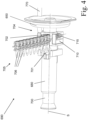
- the nose 690 comprises a guide channel 700 for guiding the fastening element with a rear front end 701 and a holder 650 arranged to be displaceable relative to the guide channel 700 in the direction of the setting axis for holding a delay element (not shown).
- the holder 650 has a bolt receptacle 680 with a feed recess 704 through which a nail strip 705 with a large number of fastening elements 706 can be fed to a firing section 702 of the guide channel 700 .
- the guide channel 700 is used at the same time as a contact pressure sensor of a contact pressure device, which has a connecting rod 770, which is also displaced when the guide channel 700 is displaced and thus indicates that the device is being pressed against a substrate.
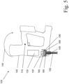
- FIG 5 shows a driving device 100 with a center of gravity 110, an energy transmission element 120 that can be moved between an initial position and a setting position for the transmission of driving energy to a fastening element (not shown), a piston drive 130 that provides the driving energy, a housing 140, and a bolt guide 150 that guides the fastening element during driving.
- the bolt guide 150 has a holder 160 and is mounted on the housing 140 only via the holder 160 .
- the holder 160 is non-rotatably connected to the rest of the bolt guide 150 .
- the holder 160 and thus the bolt guide 150 are rotatably mounted on the housing 140 with respect to a rotation about the center of gravity 110 .
- the bolt guide remains on the ground due to its inertia during the period in which the fastener is being driven into the ground and ensures guidance of the fastener until the fastener is driven into the ground.
- a rotational movement 170 of the driving-in device 100, in particular of the housing 140, caused by a recoil is compensated for and the fastening quality is improved.
- Driving device 100 has a damping element 180, which is arranged on the side of holder 160 facing away from center of gravity 110, in front of holder 160 and behind a support element 145 of housing 140, and therefore, during a recoil, prevents a rotational movement of bolt guide 150 relative to housing 140 by the Center of gravity 110 dampens.
- driving device 100 has a further damping element 185, which is arranged on the side of holder 160 facing center of gravity 110 and therefore makes no significant contribution to damping a rotational movement of bolt guide 150 during recoil.
- the holder 160 also includes a deceleration element 190 for braking the energy transmission element 120.
Landscapes
- Engineering & Computer Science (AREA)
- Mechanical Engineering (AREA)
- Portable Nailing Machines And Staplers (AREA)
Description
- Die Anmeldung betrifft eine Vorrichtung zum Eintreiben eines Befestigungselementes in einen Untergrund.
- Derartige Vorrichtungen weisen üblicherweise einen Kolben zur Übertragung von Energie auf das Befestigungselement auf. Die dazu erforderliche Energie muss dabei in sehr kurzer Zeit zur Verfügung gestellt werden, weshalb beispielsweise bei sogenannten Federnaglern zunächst eine Feder gespannt wird, welche während des Eintreibvorgangs die Spannenergie schlagartig an den Kolben abgibt und diesen auf das Befestigungselement zu beschleunigt. Die schlagartig freiwerdende Energie, mit der das Befestigungselement in den Untergrund eingetrieben wird, bewirkt einen Rückstoss, welcher einige Komponenten solcher Vorrichtungen mechanisch belastet. Wenn ein Schwerpunkt der Vorrichtung nicht auf der Bewegungsbahn des Kolbens oder ihrer Verlängerung liegt, umfasst der Rückstoss ein Drehmoment, welches die gesamte Vorrichtung verkippen lässt, während das Befestigungselement in den Untergrund eingetrieben wird.
- Aus EU 9 346 156 B1 ist eine Vorrichtung zum Eintreiben eines Befestigungselementes in einen Untergrund gemäss dem Oberbegriff des Anspruchs 1 bekannt, bei dem von einem Antreibelement angetriebene Befestiger in einem Befestigerkanal geführt sind. Eine Feder in dem Befestigerkanal lenkt während einem Befestigungsvorgang den Befestiger ab, nicht jedoch das Antreibelement. Dadurch soll das Antreibelement nach einem Verkippen des Befestigungswerkzeugs auf den Befestiger zu ausgerichtet bleiben.
- Aus
EP 3 251 802 A1 ist ein Bohrschrauber mit einer Arbeitskomponente bekannt, welche ein erstes Spannfutter für einen Bohrer und ein zweites Spannfutter für einen Schraubenantrieb umfasst. In einer ersten Stellung der Arbeitskomponente überträgt das erste Spannfutter ein Drehmoment auf einen darin befestigten Bohrer, in einer zweiten Stellung der Arbeitskomponente überträgt das zweite Spannfutter ein Drehmoment auf einen darin befestigten Schraubenantrieb. Während eines Betriebs des Bohrschraubers legt ein Steuermechanismus die Arbeitskomponente in der ersten oder zweiten Stellung fest. - Aus
DE 10 2008 000831 A1 ist ein Setzgerät mit einem Gehäuse, einer Bolzenführung und einem Magazin für Befestigungselemente bekannt. Das Magazin ist über eine Rastverbindung lösbar an dem Gehäuse festgelegt. - Aufgabe der Erfindung ist es, die Befestigungsqualität der eingangs genannten Vorrichtung zu verbessern.
- Die Aufgabe ist gelöst bei einer Vorrichtung zum Eintreiben eines Befestigungselementes in einen Untergrund, aufweisend einen Schwerpunkt, ein zwischen einer Ausgangsstellung und einer Setzstellung bewegbares Energieübertragungselement zur Übertragung von Eintreibenergie auf das Befestigungselement, einen die Eintreibenergie bereitstellenden Kolbenantrieb, ein Gehäuse sowie eine das Befestigungselement während des Eintreibens führende Bolzenführung, wobei die Bolzenführung in Bezug auf eine Drehung um den Schwerpunkt drehbeweglich an dem Gehäuse gelagert ist. Die Bolzenführung weist einen Halter auf, welcher in Bezug auf eine Drehung um den Schwerpunkt drehbeweglich an dem Gehäuse gelagert ist und ein Verzögerungselement für ein Abbremsen des Energieübertragungselements umfasst. Durch die drehbewegliche Lagerung bleibt die Bolzenführung aufgrund ihrer Massenträgheit auch dann in ihrer Position, wenn die übrige Vorrichtung aufgrund des Rückstosses bereits verkippt. Dies gilt für den Zeitraum, in dem das Befestigungselement in den Untergrund eingetrieben wird.
- Eine vorteilhafte Ausführungsform ist dadurch gekennzeichnet, dass die Vorrichtung ein Dämpfelement aufweist, welches eine Drehbewegung der Bolzenführung um den Schwerpunkt dämpft.
- Eine vorteilhafte Ausführungsform ist dadurch gekennzeichnet, dass die Bolzenführung entlang eines Winkelbereichs von mindestens 2° drehbeweglich an dem Gehäuse gelagert ist. Bevorzugt erstreckt sich der Winkelbereich über mindestens 3°, besonders bevorzugt über mindestens 5°.
- Nachfolgend werden Ausführungsformen einer Vorrichtung zum Eintreiben eines Befestigungselementes in einen Untergrund anhand von Beispielen unter Bezugnahme auf die Zeichnungen näher erläutert. Es zeigen:
- Fig. 1
- eine Seitenansicht einer Eintreibvorrichtung,
- Fig. 2
- eine Seitenansicht einer Eintreibvorrichtung mit geöffnetem Gehäuse,
- Fig. 3
- eine Teilansicht einer Eintreibvorrichtung,
- Fig. 4
- eine Schrägansicht einer Bolzenführung und
- Fig. 5
- eine Eintreibvorrichtung.
-
Fig. 1 zeigt eine Eintreibvorrichtung 10 zum Eintreiben eines Befestigungselementes, beispielsweise eines Nagels oder Bolzens, in einen Untergrund in einer Seitenansicht. Die Eintreibvorrichtung 10 weist ein nicht dargestelltes Energieübertragungselement zur Übertragung von Energie auf das Befestigungselement sowie ein Gehäuse 20 auf, in welchem das Energieübertragungselement und eine ebenfalls nicht dargestellte Antriebseinrichtung zur Beförderung des Energieübertragungselementes aufgenommen sind. - Die Eintreibvorrichtung 10 weist ferner einen Griff 30, ein Magazin 40 und eine den Griff 30 mit dem Magazin 40 verbindende Brücke 50 auf. Das Magazin ist nicht abnehmbar. An der Brücke 50 sind ein Gerüsthaken 60 zur Aufhängung der Eintreibvorrichtung 10 an einem Gerüst oder dergleichen und ein als Akku 590 ausgebildeter elektrischer Energiespeicher befestigt. An dem Griff 30 sind ein Abzug 34 sowie ein als Handschalter 35 ausgebildeter Grifffühler angeordnet. Weiterhin weist die Eintreibvorrichtung 10 einen Führungskanal 700 für eine Führung des Befestigungselementes und eine Anpresseinrichtung 750 zur Erkennung eines Abstandes der Eintreibvorrichtung 10 von einem nicht dargestellten Untergrund auf. Ein Ausrichten der Eintreibvorrichtung senkrecht zu einem Untergrund wird durch eine Ausrichthilfe 45 unterstützt.
-
Fig. 2 zeigt die Eintreibvorrichtung 10 mit geöffnetem Gehäuse 20. In dem Gehäuse 20 ist eine Antriebseinrichtung 70 zur Beförderung eines in der Zeichnung verdeckten Energieübertragungselementes aufgenommen. Die Antriebseinrichtung 70 umfasst einen nicht dargestellten Elektromotor zur Umwandlung von elektrischer Energie aus dem Akku 590 in Drehenergie, eine ein Getriebe 400 umfassende Drehmomentübertragungseinrichtung zur Übertragung eines Drehmomentes des Elektromotors auf einen als Spindeltrieb 300 ausgebildeten Bewegungsumwandler, eine einen Rollenzug 260 umfassende Kraftübertragungseinrichtung zur Übertragung einer Kraft von dem Bewegungsumwandler auf einen als Feder 200 ausgebildeten mechanischen Energiespeicher und zur Übertragung einer Kraft von der Feder auf das Energieübertragungselement. -
Fig. 3 zeigt die Eintreibvorrichtung 10 in einer Schrägansicht mit geöffnetem Gehäuse 20. In dem Gehäuse ist der vordere Rollenhalter 281 zu sehen. Das Verzögerungselement 600 wird von dem Haltering 26 in seiner Position gehalten. Die Nase 690 weist unter Anderem den Anpressfühler 760 und das Entsperrelement 720 auf. Die Anpresseinrichtung 750 weist den Führungskanal 700, welcher vorzugsweise den Anpressfühler 760 umfasst, und die Verbindungsstange 770 auf. Das Magazin 40 weist das Vorschubelement 740 und die Vorschubfeder 735 auf. - Weiterhin weist die Eintreibvorrichtung 10 einen Entriegelungsschalter 730 für eine Entriegelung des Führungskanals 700 auf, so dass der Führungskanal 700 abnehmbar ist, beispielsweise um verklemmte Befestigungselemente einfacher entfernen zu können.
-
Fig. 4 zeigt eine Nase 690 einer Vorrichtung zum Eintreiben eines Befestigungselementes in einen Untergrund in einer Schrägansicht. Die Nase 690 umfasst einen Führungskanal 700 für eine Führung des Befestigungselementes mit einem hinteren Stirnende 701 und einen relativ zu dem Führungskanal 700 in Richtung der Setzachse verschiebbar angeordneten Halter 650 zum Halten eines nicht dargestellten Verzögerungselementes. Der Halter 650 weist eine Bolzenaufnahme 680 mit einer Zuführausnehmung 704 auf, durch die hindurch ein Nagelstreifen 705 mit einer Vielzahl von Befestigungselementen 706 einem Abschussabschnitt 702 des Führungskanals 700 zuführbar ist. Der Führungskanal 700 dient gleichzeitig als Anpressfühler einer Anpresseinrichtung, welche eine Verbindungsstange 770 aufweist, welche bei einer Verschiebung des Führungskanals 700 ebenfalls verschoben wird und somit ein Anpressen der Vorrichtung an einen Untergrund anzeigt. -
Fig. 5 zeigt eine Eintreibvorrichtung 100 mit einem Schwerpunkt 110, einem zwischen einer Ausgangsstellung und einer Setzstellung bewegbaren Energieübertragungselement 120 zur Übertragung von Eintreibenergie auf ein nicht gezeigtes Befestigungselement, einem die Eintreibenergie bereitstellenden Kolbenantrieb 130, einem Gehäuse 140 sowie einer das Befestigungselement während des Eintreibens führende Bolzenführung 150. Die Bolzenführung 150 weist einen Halter 160 auf und ist nur über den Halter 160 an dem Gehäuse 140 gelagert. Der Halter 160 ist mit der übrigen Bolzenführung 150 drehfest verbunden. In Bezug auf eine Drehung um den Schwerpunkt 110 ist sind der Halter 160 und damit die Bolzenführung 150 drehbeweglich an dem Gehäuse 140 gelagert. Durch die drehbewegliche Lagerung bleibt die Bolzenführung aufgrund ihrer Massenträgheit während des Zeitraums, in dem das Befestigungselement in den Untergrund eingetrieben wird, auf dem Untergrund stehen und stellt eine Führung des Befestigungselements sicher, bis das Befestigungselement in den Untergrund eingetrieben ist. Eine von einem Rückstoss verursachte Drehbewegung 170 der Eintreibvorrichtung 100, insbesondere des Gehäuses 140, wird kompensiert und die Befestigungsqualität verbessert. - Die Eintreibvorrichtung 100 weist ein Dämpfelement 180 auf, welches auf der vom Schwerpunkt 110 abgewandten Seite des Halters 160 vor dem Halter 160 und hinter einem Stützelement 145 des Gehäuses 140 angeordnet ist und daher während eines Rückstosses eine Drehbewegung der Bolzenführung 150 relativ zum Gehäuse 140 um den Schwerpunkt 110 dämpft. Für eine symmetrische Lagerung der Bolzenführung 150 weist die Eintreibvorrichtung 100 ein weiteres Dämpfelement 185 auf, welches auf der dem Schwerpunkt 110 zugewandten Seite des Halters 160 angeordnet ist und daher während eines Rückstosses keinen nennenswerten Beitrag zur Dämpfung einer Drehbewegung der Bolzenführung 150 hat.
- Ein Winkelbereich, entlang dessen die Bolzenführung drehbeweglich an dem Gehäuse gelagert ist, hängt von einem Abstand zwischen dem Halter 160 und dem Stützelement 145 ab und beträgt vorliegend 5°. Der Halter 160 umfasst im Übrigen ein Verzögerungselement 190 für ein Abbremsen des Energieübertragungselements 120.
Claims (3)
- Vorrichtung (10) zum Eintreiben eines Befestigungselementes (706) in einen Untergrund, aufweisend einen Schwerpunkt (110), ein zwischen einer Ausgangsstellung und einer Setzstellung bewegbares Energieübertragungselement (120) zur Übertragung von Eintreibenergie auf das Befestigungselement (706), einen die Eintreibenergie bereitstellenden Kolbenantrieb (130), ein Gehäuse (140) und eine das Befestigungselement (706) während des Eintreibens führende Bolzenführung (150), wobei die Bolzenführung (150) in Bezug auf eine Drehung um den Schwerpunkt (110) drehbeweglich an dem Gehäuse (140) gelagert ist, dadurch gekennzeichnet, dass die Bolzenführung (150) einen Halter (160) aufweist, welcher in Bezug auf eine Drehung um den Schwerpunkt (110) drehbeweglich an dem Gehäuse (140) gelagert ist und ein Verzögerungselement (190) für ein Abbremsen des Energieübertragungselements (120) umfasst.
- Vorrichtung nach Anspruch 1, wobei die Vorrichtung (10) ein Dämpfelement (180) aufweist, welches eine Drehbewegung der Bolzenführung (150) um den Schwerpunkt (110) dämpft.
- Vorrichtung nach einem der vorhergehenden Ansprüche, wobei die Bolzenführung (150) entlang eines Winkelbereichs von mindestens 2°, insbesondere mindestens 3°, insbesondere mindestens 5°, drehbeweglich an dem Gehäuse (140) gelagert ist.
Applications Claiming Priority (2)
| Application Number | Priority Date | Filing Date | Title |
|---|---|---|---|
| EP17209401.3A EP3501747A1 (de) | 2017-12-21 | 2017-12-21 | Eintreibvorrichtung |
| PCT/EP2018/083635 WO2019121016A1 (de) | 2017-12-21 | 2018-12-05 | Eintreibvorrichtung |
Publications (3)
| Publication Number | Publication Date |
|---|---|
| EP3727760A1 EP3727760A1 (de) | 2020-10-28 |
| EP3727760C0 EP3727760C0 (de) | 2023-06-07 |
| EP3727760B1 true EP3727760B1 (de) | 2023-06-07 |
Family
ID=60702536
Family Applications (2)
| Application Number | Title | Priority Date | Filing Date |
|---|---|---|---|
| EP17209401.3A Withdrawn EP3501747A1 (de) | 2017-12-21 | 2017-12-21 | Eintreibvorrichtung |
| EP18808401.6A Active EP3727760B1 (de) | 2017-12-21 | 2018-12-05 | Eintreibvorrichtung |
Family Applications Before (1)
| Application Number | Title | Priority Date | Filing Date |
|---|---|---|---|
| EP17209401.3A Withdrawn EP3501747A1 (de) | 2017-12-21 | 2017-12-21 | Eintreibvorrichtung |
Country Status (5)
| Country | Link |
|---|---|
| US (1) | US20200298386A1 (de) |
| EP (2) | EP3501747A1 (de) |
| JP (1) | JP2021506609A (de) |
| CN (1) | CN111479656B (de) |
| WO (1) | WO2019121016A1 (de) |
Families Citing this family (2)
| Publication number | Priority date | Publication date | Assignee | Title |
|---|---|---|---|---|
| JP7575408B2 (ja) | 2019-06-26 | 2024-10-29 | レフォア・ゲーベーエル | ハンドヘルドセッティングツール |
| US20250353161A1 (en) * | 2024-05-20 | 2025-11-20 | Robert Bosch Gmbh | Fastener driver tool |
Citations (1)
| Publication number | Priority date | Publication date | Assignee | Title |
|---|---|---|---|---|
| EP1741519A1 (de) * | 2004-04-28 | 2007-01-10 | Max Co., Ltd. | Nagelführungsvorrichtung in einer nagelmaschine |
Family Cites Families (9)
| Publication number | Priority date | Publication date | Assignee | Title |
|---|---|---|---|---|
| DE4300871A1 (de) * | 1993-01-15 | 1994-07-21 | Reich Maschf Gmbh Karl | Einschlaggerät für mit Haltestreifen verbundene Befestigungsmittel |
| TWM263203U (en) * | 2004-04-16 | 2005-05-01 | Chi-Tian Lin | Stack push structure of air stapler |
| DE102008000831A1 (de) * | 2008-03-26 | 2009-10-01 | Hilti Aktiengesellschaft | Setzgerät |
| CN201483456U (zh) * | 2009-07-06 | 2010-05-26 | 浙江荣鹏气动工具有限公司 | 固定式散钉枪钉头装置 |
| US9346156B1 (en) * | 2012-02-21 | 2016-05-24 | Senco Brands, Inc. | Skewed fastener track for improved alignment and fastener drivability |
| KR20140005862U (ko) * | 2013-05-09 | 2014-11-19 | 제일타카 주식회사 | 고장 방지구조의 네일러 |
| CN203510371U (zh) * | 2013-10-11 | 2014-04-02 | 夏则荣 | 一种木托盘打钉装置 |
| EP3251802A4 (de) * | 2015-01-29 | 2018-09-26 | Positec Power Tools (Suzhou) Co., Ltd | Tragbares elektrowerkzeug und betriebsverfahren dafür |
| CN106625432B (zh) * | 2016-12-19 | 2018-10-02 | 重庆金诺克机械制造有限公司 | 防止射钉反弹的射钉器 |
-
2017
- 2017-12-21 EP EP17209401.3A patent/EP3501747A1/de not_active Withdrawn
-
2018
- 2018-12-05 EP EP18808401.6A patent/EP3727760B1/de active Active
- 2018-12-05 WO PCT/EP2018/083635 patent/WO2019121016A1/de not_active Ceased
- 2018-12-05 US US16/769,421 patent/US20200298386A1/en not_active Abandoned
- 2018-12-05 JP JP2020534905A patent/JP2021506609A/ja active Pending
- 2018-12-05 CN CN201880081224.6A patent/CN111479656B/zh active Active
Patent Citations (1)
| Publication number | Priority date | Publication date | Assignee | Title |
|---|---|---|---|---|
| EP1741519A1 (de) * | 2004-04-28 | 2007-01-10 | Max Co., Ltd. | Nagelführungsvorrichtung in einer nagelmaschine |
Also Published As
| Publication number | Publication date |
|---|---|
| AU2018390004A1 (en) | 2020-06-11 |
| EP3727760C0 (de) | 2023-06-07 |
| EP3501747A1 (de) | 2019-06-26 |
| CN111479656A (zh) | 2020-07-31 |
| WO2019121016A1 (de) | 2019-06-27 |
| CN111479656B (zh) | 2023-08-22 |
| JP2021506609A (ja) | 2021-02-22 |
| EP3727760A1 (de) | 2020-10-28 |
| US20200298386A1 (en) | 2020-09-24 |
Similar Documents
| Publication | Publication Date | Title |
|---|---|---|
| WO2009109247A1 (de) | Zusatzhandgriff sowie handwerkzeugmaschine | |
| EP0782898B1 (de) | Verfahren zum Befestigen eines Spannaufsatzes auf einem Werkstück und Vorrichtung zu seiner Durchführung | |
| DE102009054930B4 (de) | Bohrmaschine | |
| WO2012110453A1 (de) | Drehmomentübertragungseinrichtung in form eines bitfutters | |
| EP3727760B1 (de) | Eintreibvorrichtung | |
| EP2415881B1 (de) | Haltevorrichtung für eine Bohrstange einer Stichlochbohrmaschine sowie Verfahren zum Entfernen einer Bohrstange | |
| DE3310147C2 (de) | ||
| EP0727547A1 (de) | Befestigungselement für Isolationsmaterialien | |
| DE4141916C2 (de) | Vorrichtung zum Eindrehen und Setzen von selbstbohrenden Zugblindnieten | |
| EP3128935B1 (de) | Werkzeugvorrichtung, insbesondere handwerkzeugvorrichtung, mit drehmomentbegrenzung | |
| EP3898114B1 (de) | Eintreibvorrichtung | |
| DE102004017940A1 (de) | Schlagwerk für eine Handwerkzeugmaschine | |
| DE102016110111A1 (de) | Bohrfutter | |
| WO1993017315A1 (de) | Vorrichtung zum anbringen eines auswuchtgewichtes an einem fahrzeugrad | |
| EP3898113A1 (de) | Vorrichtung, eintreibgerät und verfahren | |
| EP3898115B1 (de) | Eintreibvorrichtung | |
| DE102004042952A1 (de) | Schraubgerät mit axial wirkendem Schlagmechanismus | |
| EP3898111B1 (de) | Eintreibvorrichtung | |
| WO2016202897A1 (de) | Verfahren zum befestigen einer isolierung an einer wand | |
| DE1299579B (de) | Transportables, motorisch angetriebenes Drehschlaggeraet | |
| EP2632347A1 (de) | Chirurgisches instrument | |
| EP3566813B1 (de) | Schraubenkopfhalter für ein handgeführtes schraubwerkzeug | |
| EP4201597A1 (de) | Eintreibvorrichtung und -verfahren | |
| EP4279197A1 (de) | Vorrichtung zur vereinzelung von drähten oder stäben | |
| DE102025143534A1 (de) | Heftgerät, insbesondere elektrisches Heftgerät oder pneumatisches Heftgerät |
Legal Events
| Date | Code | Title | Description |
|---|---|---|---|
| STAA | Information on the status of an ep patent application or granted ep patent |
Free format text: STATUS: UNKNOWN |
|
| STAA | Information on the status of an ep patent application or granted ep patent |
Free format text: STATUS: THE INTERNATIONAL PUBLICATION HAS BEEN MADE |
|
| PUAI | Public reference made under article 153(3) epc to a published international application that has entered the european phase |
Free format text: ORIGINAL CODE: 0009012 |
|
| STAA | Information on the status of an ep patent application or granted ep patent |
Free format text: STATUS: REQUEST FOR EXAMINATION WAS MADE |
|
| 17P | Request for examination filed |
Effective date: 20200721 |
|
| AK | Designated contracting states |
Kind code of ref document: A1 Designated state(s): AL AT BE BG CH CY CZ DE DK EE ES FI FR GB GR HR HU IE IS IT LI LT LU LV MC MK MT NL NO PL PT RO RS SE SI SK SM TR |
|
| AX | Request for extension of the european patent |
Extension state: BA ME |
|
| DAV | Request for validation of the european patent (deleted) | ||
| DAX | Request for extension of the european patent (deleted) | ||
| GRAP | Despatch of communication of intention to grant a patent |
Free format text: ORIGINAL CODE: EPIDOSNIGR1 |
|
| STAA | Information on the status of an ep patent application or granted ep patent |
Free format text: STATUS: GRANT OF PATENT IS INTENDED |
|
| INTG | Intention to grant announced |
Effective date: 20230104 |
|
| GRAS | Grant fee paid |
Free format text: ORIGINAL CODE: EPIDOSNIGR3 |
|
| GRAA | (expected) grant |
Free format text: ORIGINAL CODE: 0009210 |
|
| STAA | Information on the status of an ep patent application or granted ep patent |
Free format text: STATUS: THE PATENT HAS BEEN GRANTED |
|
| AK | Designated contracting states |
Kind code of ref document: B1 Designated state(s): AL AT BE BG CH CY CZ DE DK EE ES FI FR GB GR HR HU IE IS IT LI LT LU LV MC MK MT NL NO PL PT RO RS SE SI SK SM TR |
|
| REG | Reference to a national code |
Ref country code: GB Ref legal event code: FG4D Free format text: NOT ENGLISH |
|
| REG | Reference to a national code |
Ref country code: CH Ref legal event code: EP Ref country code: AT Ref legal event code: REF Ref document number: 1573575 Country of ref document: AT Kind code of ref document: T Effective date: 20230615 Ref country code: DE Ref legal event code: R096 Ref document number: 502018012421 Country of ref document: DE |
|
| U01 | Request for unitary effect filed |
Effective date: 20230705 |
|
| U07 | Unitary effect registered |
Designated state(s): AT BE BG DE DK EE FI FR IT LT LU LV MT NL PT SE SI Effective date: 20230718 |
|
| REG | Reference to a national code |
Ref country code: LT Ref legal event code: MG9D |
|
| PG25 | Lapsed in a contracting state [announced via postgrant information from national office to epo] |
Ref country code: NO Free format text: LAPSE BECAUSE OF FAILURE TO SUBMIT A TRANSLATION OF THE DESCRIPTION OR TO PAY THE FEE WITHIN THE PRESCRIBED TIME-LIMIT Effective date: 20230907 Ref country code: ES Free format text: LAPSE BECAUSE OF FAILURE TO SUBMIT A TRANSLATION OF THE DESCRIPTION OR TO PAY THE FEE WITHIN THE PRESCRIBED TIME-LIMIT Effective date: 20230607 |
|
| PG25 | Lapsed in a contracting state [announced via postgrant information from national office to epo] |
Ref country code: RS Free format text: LAPSE BECAUSE OF FAILURE TO SUBMIT A TRANSLATION OF THE DESCRIPTION OR TO PAY THE FEE WITHIN THE PRESCRIBED TIME-LIMIT Effective date: 20230607 Ref country code: HR Free format text: LAPSE BECAUSE OF FAILURE TO SUBMIT A TRANSLATION OF THE DESCRIPTION OR TO PAY THE FEE WITHIN THE PRESCRIBED TIME-LIMIT Effective date: 20230607 Ref country code: GR Free format text: LAPSE BECAUSE OF FAILURE TO SUBMIT A TRANSLATION OF THE DESCRIPTION OR TO PAY THE FEE WITHIN THE PRESCRIBED TIME-LIMIT Effective date: 20230908 |
|
| PG25 | Lapsed in a contracting state [announced via postgrant information from national office to epo] |
Ref country code: SK Free format text: LAPSE BECAUSE OF FAILURE TO SUBMIT A TRANSLATION OF THE DESCRIPTION OR TO PAY THE FEE WITHIN THE PRESCRIBED TIME-LIMIT Effective date: 20230607 |
|
| PG25 | Lapsed in a contracting state [announced via postgrant information from national office to epo] |
Ref country code: IS Free format text: LAPSE BECAUSE OF FAILURE TO SUBMIT A TRANSLATION OF THE DESCRIPTION OR TO PAY THE FEE WITHIN THE PRESCRIBED TIME-LIMIT Effective date: 20231007 |
|
| PG25 | Lapsed in a contracting state [announced via postgrant information from national office to epo] |
Ref country code: SM Free format text: LAPSE BECAUSE OF FAILURE TO SUBMIT A TRANSLATION OF THE DESCRIPTION OR TO PAY THE FEE WITHIN THE PRESCRIBED TIME-LIMIT Effective date: 20230607 Ref country code: SK Free format text: LAPSE BECAUSE OF FAILURE TO SUBMIT A TRANSLATION OF THE DESCRIPTION OR TO PAY THE FEE WITHIN THE PRESCRIBED TIME-LIMIT Effective date: 20230607 Ref country code: RO Free format text: LAPSE BECAUSE OF FAILURE TO SUBMIT A TRANSLATION OF THE DESCRIPTION OR TO PAY THE FEE WITHIN THE PRESCRIBED TIME-LIMIT Effective date: 20230607 Ref country code: IS Free format text: LAPSE BECAUSE OF FAILURE TO SUBMIT A TRANSLATION OF THE DESCRIPTION OR TO PAY THE FEE WITHIN THE PRESCRIBED TIME-LIMIT Effective date: 20231007 Ref country code: CZ Free format text: LAPSE BECAUSE OF FAILURE TO SUBMIT A TRANSLATION OF THE DESCRIPTION OR TO PAY THE FEE WITHIN THE PRESCRIBED TIME-LIMIT Effective date: 20230607 |
|
| U20 | Renewal fee for the european patent with unitary effect paid |
Year of fee payment: 6 Effective date: 20231227 |
|
| PG25 | Lapsed in a contracting state [announced via postgrant information from national office to epo] |
Ref country code: PL Free format text: LAPSE BECAUSE OF FAILURE TO SUBMIT A TRANSLATION OF THE DESCRIPTION OR TO PAY THE FEE WITHIN THE PRESCRIBED TIME-LIMIT Effective date: 20230607 |
|
| REG | Reference to a national code |
Ref country code: DE Ref legal event code: R097 Ref document number: 502018012421 Country of ref document: DE |
|
| PLBE | No opposition filed within time limit |
Free format text: ORIGINAL CODE: 0009261 |
|
| STAA | Information on the status of an ep patent application or granted ep patent |
Free format text: STATUS: NO OPPOSITION FILED WITHIN TIME LIMIT |
|
| 26N | No opposition filed |
Effective date: 20240308 |
|
| REG | Reference to a national code |
Ref country code: CH Ref legal event code: PL |
|
| PG25 | Lapsed in a contracting state [announced via postgrant information from national office to epo] |
Ref country code: MC Free format text: LAPSE BECAUSE OF FAILURE TO SUBMIT A TRANSLATION OF THE DESCRIPTION OR TO PAY THE FEE WITHIN THE PRESCRIBED TIME-LIMIT Effective date: 20230607 |
|
| PG25 | Lapsed in a contracting state [announced via postgrant information from national office to epo] |
Ref country code: MC Free format text: LAPSE BECAUSE OF FAILURE TO SUBMIT A TRANSLATION OF THE DESCRIPTION OR TO PAY THE FEE WITHIN THE PRESCRIBED TIME-LIMIT Effective date: 20230607 |
|
| REG | Reference to a national code |
Ref country code: IE Ref legal event code: MM4A |
|
| PG25 | Lapsed in a contracting state [announced via postgrant information from national office to epo] |
Ref country code: IE Free format text: LAPSE BECAUSE OF NON-PAYMENT OF DUE FEES Effective date: 20231205 |
|
| PG25 | Lapsed in a contracting state [announced via postgrant information from national office to epo] |
Ref country code: CH Free format text: LAPSE BECAUSE OF NON-PAYMENT OF DUE FEES Effective date: 20231231 |
|
| PG25 | Lapsed in a contracting state [announced via postgrant information from national office to epo] |
Ref country code: IE Free format text: LAPSE BECAUSE OF NON-PAYMENT OF DUE FEES Effective date: 20231205 Ref country code: CH Free format text: LAPSE BECAUSE OF NON-PAYMENT OF DUE FEES Effective date: 20231231 |
|
| U20 | Renewal fee for the european patent with unitary effect paid |
Year of fee payment: 7 Effective date: 20241227 |
|
| PG25 | Lapsed in a contracting state [announced via postgrant information from national office to epo] |
Ref country code: CY Free format text: LAPSE BECAUSE OF FAILURE TO SUBMIT A TRANSLATION OF THE DESCRIPTION OR TO PAY THE FEE WITHIN THE PRESCRIBED TIME-LIMIT; INVALID AB INITIO Effective date: 20181205 |
|
| PG25 | Lapsed in a contracting state [announced via postgrant information from national office to epo] |
Ref country code: HU Free format text: LAPSE BECAUSE OF FAILURE TO SUBMIT A TRANSLATION OF THE DESCRIPTION OR TO PAY THE FEE WITHIN THE PRESCRIBED TIME-LIMIT; INVALID AB INITIO Effective date: 20181205 |
|
| PG25 | Lapsed in a contracting state [announced via postgrant information from national office to epo] |
Ref country code: TR Free format text: LAPSE BECAUSE OF FAILURE TO SUBMIT A TRANSLATION OF THE DESCRIPTION OR TO PAY THE FEE WITHIN THE PRESCRIBED TIME-LIMIT Effective date: 20230607 |
|
| PGFP | Annual fee paid to national office [announced via postgrant information from national office to epo] |
Ref country code: GB Payment date: 20251219 Year of fee payment: 8 |
|
| U20 | Renewal fee for the european patent with unitary effect paid |
Year of fee payment: 8 Effective date: 20251230 |