EP3728143B1 - Maschine und verfahren zur herstellung von glasgegenständen - Google Patents
Maschine und verfahren zur herstellung von glasgegenständen Download PDFInfo
- Publication number
- EP3728143B1 EP3728143B1 EP18833988.1A EP18833988A EP3728143B1 EP 3728143 B1 EP3728143 B1 EP 3728143B1 EP 18833988 A EP18833988 A EP 18833988A EP 3728143 B1 EP3728143 B1 EP 3728143B1
- Authority
- EP
- European Patent Office
- Prior art keywords
- lower portion
- axis
- blank
- parts
- mould
- Prior art date
- Legal status (The legal status is an assumption and is not a legal conclusion. Google has not performed a legal analysis and makes no representation as to the accuracy of the status listed.)
- Active
Links
Images



Classifications
-
- C—CHEMISTRY; METALLURGY
- C03—GLASS; MINERAL OR SLAG WOOL
- C03B—MANUFACTURE, SHAPING, OR SUPPLEMENTARY PROCESSES
- C03B9/00—Blowing glass; Production of hollow glass articles
- C03B9/13—Blowing glass; Production of hollow glass articles in gob feeder machines
- C03B9/193—Blowing glass; Production of hollow glass articles in gob feeder machines in "press-and-blow" machines
- C03B9/197—Construction of the blank mould
-
- C—CHEMISTRY; METALLURGY
- C03—GLASS; MINERAL OR SLAG WOOL
- C03B—MANUFACTURE, SHAPING, OR SUPPLEMENTARY PROCESSES
- C03B9/00—Blowing glass; Production of hollow glass articles
- C03B9/30—Details of blowing glass; Use of materials for the moulds
- C03B9/32—Giving special shapes to parts of hollow glass articles
- C03B9/33—Making hollow glass articles with feet or projections; Moulds therefor
Definitions
- the present invention relates to a machine for manufacturing glass objects.
- the machine receives glass brought to a temperature sufficient to allow it to flow by gravity.
- the malleable glass is shaped and cooled.
- US 2,115,765 describes a tool for forming a grip handle on a molded glass cover.
- the mold is made of an outer crown and an inner part with two articulated jaws. Once the glass is poured and molded, the interior part is lifted and the jaws are opened releasing the handle.
- Such a tool is unsuitable for mass production.
- the jaw joint is located in a high temperature zone requiring either special alloys or very frequent replacement of parts.
- the mechanism itself is axially bulky and unsuitable for drinking glasses.
- CA 450 853 proposes to pinch, after molding, an area to be deformed. However, at this moment, the glass is cooled sufficiently to be not very deformable and to require a mechanical force such that the risk of breaking the glass object is high.
- US 1,603,524 describes a method of manufacturing stemmed glass, comprising depositing a load of glass in a mold with angular sections, moving a pressing tool in the mold to form a blowing blank, the same tool forming the foot and base of a part with blowing the blank from the same load of glass, the same tool forming an initial opening in the blank, and then blowing the blank.
- the applicant has sought to remedy these drawbacks.
- the applicant has sought to make the manufacture of the stem and the manufacture of the parison of a drinking glass as independent as possible. This allows reduced handling and more efficient use of the machines, for example a maintenance stop on a glass foot pressing machine becomes without influence on the production of the parisons.
- glass welding requires thicknesses of similar materials to benefit from homogeneous cooling, high thicknesses of the order of 5 to 6 mm and requires an input of energy.
- the other methods of fixing the foot and the parison have not been successful to date, whether for aesthetic reasons, daily use or even strength.
- the invention offers freedom of form in the parison.
- the invention also offers the freedom of choice of glass thickness.
- the invention proposes a machine for manufacturing glass objects, in particular stemmed glass, comprising a blank mold configured to receive glass at flow temperature, and a pressing punch movable in translation along a first axis, characterized in that the blank mold comprises a one-piece upper part of upwardly flared shape, and a lower part of non-upwardly flared shape and produced in several parts, the parts of the lower part being movable in translation with a component according to axes arranged in a plane normal to the first axis, the upper part having a minimum dimension along any axis normal to the first axis, greater than the maximum dimension of the lower part along said axis normal to the first axis so that the molded object in the lower part can pass into the upper part in translation along the first axis. It is thus possible to manufacture a blank of non-monotonic diameter in the blank mold.
- the upper part constitutes a parison mold and the lower part constitutes an organ mold placed under the parison.
- the parison can be provided with a protruding functional member.
- the parts of the lower part are at least two in number. In practice, two to ten identical parts can be provided, together forming a circle.
- the parts of the lower part are mold sectors.
- the pieces of the lower part define a lateral protuberance.
- the lateral growth is preferably annular.
- the blank can be rotated for a finishing step.
- the parts of the lower part are movable in translation in the plane normal to the first axis.
- the mold has a molding position in which the pieces of the lower part are clamped together defining a molding surface open towards the upper part and closed laterally and downwards, and a molding surface. open position in which the parts of the lower part are spaced apart from each other. The blank can then be removed from the mold.
- the machine comprises an actuator arranged under the lower part and acting on the parts of the lower part between a clamped position and a position separated from each other.
- the actuator can be preserved from the heat of the workpiece.
- inclined ramps transforming the translation along the first axis into translation along the second axis.
- the machine is compact along the second axis allowing mounting on a carousel.
- the machine comprises a finishing mold mounted downstream of the blank mold.
- the finishing mold is configured to be without deforming contact with the lower part of the blank corresponding to the lower part of the blank mold.
- the lower part of the blank is preserved.
- the lower part of the blank is formed in one step. If necessary, a blow molding can be carried out in the finishing mold.
- the lower part of the blank mold is frustoconical with an annular groove.
- the lower part of the blank mold has freedom of shape and the blank can be brought to its final shape by the lower part of the blank mold.
- a first type of machine comprises a blank mold and a finishing mold for manufacture in the so-called press / blown technology. From a drop of glass poured into the blank mold, the glass is pressed into said blank mold.
- the blank mold has a one-piece molding wall.
- a pressing punch is provided at the open end of the blank mold. Once the drop of glass has been poured into the blank mold, the pressing punch is lowered by translation and comes to apply the glass against the outer wall.
- the blank mold makes it possible to form a blank, the cutting part or parison of which has an increasing diameter going upwards. In other words, demolding requires that the diameter of the parison be monotonically increasing upwards.
- a blank is removed from the blank mold. Then, the blank elongates with rotation in the finishing mold where the blowing takes place to press the wall of the blank against the molding wall of the finishing mold.
- the parison is then heat-fixed by welding on a glass foot produced in parallel.
- the Applicant also knows the technique of pressing alone which requires a monotonous parison diameter increasing upwards and a high thickness of glass.
- the high glass thickness is necessitated by the low fluidity of the glass within the single mold and the difficulty of hot pressing at temperatures at which most structural steels lose much of their mechanical properties.
- the high glass thickness makes the final product heavier and increases its cost price at each stage of production.
- the high glass thickness also reduces the designer's freedom to shape the object.
- the invention aims to remedy the drawbacks of the first type of machine while retaining its advantages, in particular compared to pressing machines alone.
- the invention aims to offer creative freedom to designers and designers of glasses, in particular drinking glasses, in particular stemmed glasses, goblet glasses, etc.
- the parison is free-form and independent from the rest of the glass.
- the parison is made in press-blown with a multi-piece blank mold.
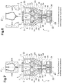
- the machine for manufacturing glass objects comprises a blank mold 1 configured to receive glass at flow temperature, and a pressing punch 2 movable in translation along a first axis, generally vertical, alternatively.
- the first axis is here called Z axis.
- the punch 2 has a shape of revolution with a monotonic diameter increasing from the bottom.
- the punch 2 is made in one piece of refractory alloy.
- the punch 2 is driven by a linear actuator, in particular pneumatic or electric.
- the punch 2 is designed to form the inner surface of a glass blank 51.
- the blank mold 1 comprises an upper part 3 in one piece having an upper molding concavity 4 or an inner surface of a shape that is flared upwards.
- the upper molding concavity 4 has a shape of revolution with a monotonous diameter increasing from the bottom.
- the upper molding concavity 4 has a small diameter opening at its lower end and a large diameter opening at its upper end.
- the upper molding concavity 4 is coaxial with the punch 2.
- the upper part 3 is made in one piece from a refractory alloy.
- a blank gripping clamp 55 On the upper part 3, is mounted a blank gripping clamp 55.
- the upper part 3 comprises an upper rim 5 extending from the upper end of the upper molding concavity 4.
- the upper rim 5 has a planar upper surface 6 normal to the Z axis.
- the rim upper 5 is annular.
- the upper rim 5 has a peripheral surface 7 parallel to the Z axis and a lower surface 8 parallel to the upper surface 6. Between the peripheral surface 7 and the lower surface 8 is formed an annular shoulder 9.
- the shoulder 9 allows stable mounting and centering on a support pot, see below.
- the upper part 3 comprises a mold body 10 extending downwardly from the upper rim 5.
- the molding body 10 has the general shape of a cup open at the bottom.
- the molding body 10 is annular.
- the molding body 10 comprises an elongated wall 11 along the Z axis and a bottom 12 in the form of a disc in a plane normal to the Z axis.
- the elongated wall 11 has a peripheral surface, here in the form of a cylinder of revolution, and a Inner frustoconical molding surface forming part of the upper molding concavity 4.
- the bottom 12 has a flat lower surface.
- the flat bottom surface is normal to the Z axis.
- the bottom 12 has an upper surface forming a molding surface forming part of the upper molding concavity 4.
- the upper surface is continuous with the internal molding surface of the elongated wall 11.
- the blank mold 1 comprises a lower part 13 made of several molding parts.
- the term “molding part” is understood to mean a structural element in contact with the molten glass during molding.
- the lower part 13 has an upper surface in contact with the lower surface of the upper part 3.
- the lower part 13 is produced in angular sectors 15 of number between two and ten. A number chosen between four and ten is preferable in order to limit the radial travel, the number being able to take account of the diameter of the part and of the variation in diameter between a local minimum and a local maximum situated downwards.
- the angular sectors 15 are movable between a molding position and a demolding position. In the molding position, the angular sectors 15 form a lower molding concavity 14 of non-flared shape upwards.
- the lower molding concavity 14 is closed at the bottom.
- the lower mold concavity 14 is open upwardly in communication with the upper mold concavity.
- the angular sectors 15 have separating planes passing through the Z axis.
- the angular sectors 15 are movable in translation with a component along a second axis perpendicular to the Z axis.
- the angular sectors 15 are movable in translation in a plane. normal to the Z axis.
- the lower molding concavity 14 may or may not be circular in shape.
- the lower molding concavity 14 is of non-monotonically decreasing diameter downwards while the upper molding concavity 4 is of monotonically decreasing diameter downwards.
- the lower molding concavity 14 has an annular groove to form an annular bead in a lower part of the blank.
- the lower molding concavity 14 is free to exhibit variations in radial dimension, increasing and decreasing towards the bottom.
- the lower molding concavity 14 may require the radial movement of the angular sectors 15 for demolding while the upper molding concavity 4 is demouldable by relative axial movement of the blank and of said upper molding concavity 4.
- the upper part 3 has, along any axis in a plane normal to the first axis, a minimum dimension greater than the maximum dimension of the lower part according to said axis normal to the first axis so that the object molded in the lower part can pass into the upper part in translation along the first axis.
- the angular sectors 15 are angularly spaced from one another and free up a space of radial dimension greater than or equal to the minimum radial dimension of the upper molding concavity 4.
- the lower part 13 in the molding position, has a frustoconical peripheral surface 16.
- the frustoconical peripheral surface 16 is in contact with a frustoconical guide 20.
- the lower part 13 has a lower zone 17 cooperating with a support arm 21. Cooperation can be ensured by axial securing and radial freedom, for example by an end of the T-shaped arm 21 arranged in a corresponding concave shape.
- the frustoconical guide 20 and the support arm 21 are integral with one another.
- the frustoconical guide 20 and the support arm 21 are movable in translation along the Z axis.
- the frustoconical guide 20 and the support arm 21 are driven by an actuator 22.
- the actuator 22 comprises, here, a pneumatic - piston assembly. 23 and cylinder 24 -.
- the actuator 22 is capable of moving the frustoconical guide 20 and the support arm 21 between a high position and a low position and of maintaining them in each of these positions.
- the high position corresponds to the molding position.
- the low position corresponds to the demoulding position.
- the angular sectors 15 are indexed to the frustoconical guide 20 in the other direction, in particular by means of a T-rail 25 passing through a slot 26 made in the frustoconical guide 20.
- the T-rail 25 comes into contact with the frustoconical outer surface of the frustoconical guide 20.
- the T-shaped rails 25 and the outer surfaces of the angular sectors 15 form inclined ramps transforming the translation along the first axis into translation in the plane normal to the first axis in cooperation with the inner and outer frustoconical surfaces of the taper guide 20.
- the T-rail 25 comprises a web 27 and a bar 28.
- the web 27 is fixed at one end to the angular sector 15 and supports at its opposite end the bar 28, the web 27 passing through said slot 26.
- the core 27 has the shape of a parallelogram.
- the bar 28 protrudes beyond the frustoconical guide 20. Thus in the opposite direction, the downward movement of the frustoconical guide 20 forces the angular sectors 15 to move away. The bar 28 then exerts a traction on the corresponding angular sector 20.
- the frustoconical guide 20 is extended downwards by a sleeve 30 surrounding the arm 21.
- the sleeve 30 is pierced by an oblong hole 31.
- the upper part 3 of the blank mold 1 rests by the rim 5 on an external support 32.
- the support outer 32 is here annular with an upper cylindrical wall 33 supporting said upper part 3, and a bottom 34 provided with a central through hole 35.
- the sleeve 30 and the arm 21 pass through said hole 35.
- a transverse bar 36 is fixed to the external support 32.
- the transverse bar 36 passes through the hole 35.
- the transverse bar 36 passes through the oblong hole 31 of the sleeve 30 and of the arm 21.
- the oblong hole 31 has an axis normal to the Z axis and has a main dimension or large diameter along the Z axis.
- the sleeve 30 and the arm 21 are rotated to the outer support 32 while having freedom in translation along the Z axis within the limit imposed by the main dimension of the oblong hole 31.
- the machine also comprises a punch or pressing core 2 movable in translation along the Z axis.
- the punch 2 serves as a piston while the blank mold 1 serves as a cylinder for forming the blank from a drop of glass 50 received in the blank mold 1.
- the punch 2 has a shape and a dimension such that the blank has a relatively uniform thickness in the blank part corresponding to the upper part 3 of the blank mold 1.
- the punch 2 remains substantially above the angular sectors 15, in particular at a level higher than the lower surface of the upper part 3.
- the actuator 22 pushes the frustoconical guide 20 and the arm 21 upwards.
- the angular sectors 15 of the lower part 13 close.
- the lower part 13 and the upper part 3 form a blank mold closed at the bottom.
- a drop of glass 50 is loaded into the blank mold 1.
- the drop of glass 50 has a temperature and therefore a viscosity making it suitable for being shaped.
- the glass drop is located at the bottom of the concavity of the blank mold 1.
- the punch 2 descends and comes into contact with the drop of glass 50.
- the punch 2 causes the glass to flow between the walls of the blank mold 1 and of the punch 2 itself.
- the punch 2 also causes the glass to flow downwards in the lower part 13, between the angular sectors 15, and upwards to form a rim 52 in the clamp 55.
- the blank 51 comprises a rim 52, an upper part or parison 53, and a lower part or functional member 54.
- the parison 53 is shaped by the punch 2 and the upper concavity 4.
- the parison 53 is of flared shape so as to be demolded from the one-piece upper part 3.
- the member functional 54 is of non-flared shape.
- the functional member 54 is, here, a Z axis stud directed downwards and having an annular bead projecting radially.
- the punch 2 is reassembled and is thus released from the blank 51.
- the temperature of the glass of the blank having fallen, the blank 51 retains its shape and its shape. dimension.
- the actuator 22 pulls the frustoconical guide 20 and the arm 21 downwards.
- the angular sectors 15 of the lower part 13 move apart.
- the lower part 13 of the blank mold 1 reaches an open position.
- the part of the blank 51 located under the upper part 3 of the blank mold 1 is released.
- a sixth step the whole of the blank mold 1 is released downwards.
- the blank 51 is held by the clamp 55 in engagement with the rim 52.
- the blank 51 is released from the upper part 13.
- the blank 51 can be retained by an upper edge.
- a finishing mold 60 made in several angular sectors can be brought by a movement in a plane normal to the Z axis.
- the finishing mold 60 comes into contact with the upper part of the blank.
- the finishing mold 60 is preferably distant from the lower part of the blank.
- the finishing mold 60 has no deforming contact with the lower part of the blank previously formed by the lower part of the blank mold.
- the finishing mold 60 is closed around the blank 51 and pressurized air blowing is carried out in the concavity of the blank 51.
- the parison resulting from the blank 51 can thus take a form balloon glass or more generally glass, the mouth of which has a diameter smaller than another part of the parison.
- the lower part of the blank 51 corresponding to the lower part 13 of the blank mold 1 has a free form in the envelope formed by the minimums of the transverse dimensions of the upper part 3.
- the lower part 13 of the blank mold 1 forms a mold organ placed under the parison.
- the lower part 13 of the blank mold 1 defines a lateral protuberance, preferably annular, of the lower part of the blank 51.
- the finishing mold 60 is moved apart and the parison resulting from the blank 51 is demolded.
- the invention provides a machine and a production method offering freedom of design of a glass object considerably wider than before.
- the parison can be blown while the lower part can be provided with a bulge facilitating the mechanical strength of the assembly.
Landscapes
- Engineering & Computer Science (AREA)
- Chemical & Material Sciences (AREA)
- Manufacturing & Machinery (AREA)
- Materials Engineering (AREA)
- Organic Chemistry (AREA)
- Physics & Mathematics (AREA)
- Geometry (AREA)
- Moulds For Moulding Plastics Or The Like (AREA)
- Manufacturing Of Magnetic Record Carriers (AREA)
- Containers Having Bodies Formed In One Piece (AREA)
- Re-Forming, After-Treatment, Cutting And Transporting Of Glass Products (AREA)
Claims (11)
- Maschine zur Herstellung von Glasgegenständen, insbesondere Stielglas, umfassend eine Rohlingsform (1), konfiguriert, um Glas bei Fließtemperatur zu empfangen, und einen entlang einer ersten Achse translatorisch bewegbaren Pressstempel (2), dadurch gekennzeichnet, dass die Rohlingsform (1) einen aus einem Stück bestehenden oberen Abschnitt (3) mit nach oben aufgeweiteter Form und einen aus mehreren Teilen bestehenden unteren Abschnitt (13) mit nach oben nicht aufgeweiteter Form umfasst, wobei die Teile des unteren Abschnitts (13) mit einer Komponente entlang von Achsen, die in einer Ebene senkrecht zur ersten Achse angeordnet sind, translatorisch bewegbar sind, wobei der obere Abschnitt (3) entlang allen senkrechten Achsen zur ersten Achse eine minimale Abmessung aufweist, die größer ist als die maximale Abmessung des unteren Abschnitts (13) entlang der Achse senkrecht zur ersten Achse, so dass der im unteren Abschnitt (13) gegossene Gegenstand translatorisch in den oberen Abschnitt (3) gelangen kann, entlang der ersten Achse.
- Maschine nach Anspruch 1, wobei der obere Abschnitt (3) eine Külbelform und der untere Abschnitt (13) eine Organform bildet, die unter der Külbelform angeordnet ist.
- Maschine nach Anspruch 1 oder 2, wobei die Anzahl der Teile des unteren Abschnitts (13) mindestens zwei ist.
- Maschine nach einem der vorhergehenden Ansprüche, wobei die Teile des unteren Abschnitts (13) Gussform-Sektoren (15) sind.
- Maschine nach einem der vorhergehenden Ansprüche, wobei die Teile des unteren Abschnitts (13) einen seitlichen Vorsprung bilden, vorzugsweise ringförmig.
- Maschine nach einem der vorhergehenden Ansprüche, wobei die Teile des unteren Abschnitts (13) in der zur ersten Achse senkrechten Ebene translatorisch beweglich sind.
- Maschine nach einem der vorhergehenden Ansprüche, wobei die Gussform eine Gussstellung hat, in der die Teile des unteren Abschnitts (13) gegeneinander geklemmt sind und so eine Gussformoberfläche (14) bilden, die zum oberen Abschnitt (3) hin offen und seitlich und nach unten geschlossen ist, und eine Offenstellung, in der die Teile des unteren Abschnitts (13) voneinander beabstandet sind, wobei dann der Rohling (51) entformt werden kann.
- Maschine nach einem der vorhergehenden Ansprüche, umfassend einen unter dem unteren Abschnitt (13) angeordneten Aktuator (22), der auf die Teile des unteren Abschnitts wirkt (13), zwischen einer Klemmposition und einer voneinander beabstandeten Position.
- Maschine nach Anspruch 8, in der zwischen dem Aktuator (22) und den Teilen des unteren Abschnitts (13) geneigte Rampen vorgesehen sind, die die Translation entlang der ersten Achse in eine Translation entlang der zweiten Achse umwandeln.
- Maschine nach einem der vorhergehenden Ansprüche, umfassend eine Fertigform (60), die der Rohlingsform (1) nachgeschaltet eingebaut ist (1), wobei die Fertigform (60) so konfiguriert ist, dass sie mit dem unteren Abschnitt (13) des Rohlings (51), der dem unteren Abschnitt (13) der Rohlingsform (1) entspricht, keinen deformierenden Kontakt hat.
- Verfahren zur Herstellung von Glasgegenständen, insbesondere Stielglas, umfassend:- Bereitstellen einer Rohlingsform (1) mit geschlossenem Boden, umfassend einen aus einem Stück bestehenden oberen Abschnitt (3) mit nach oben aufgeweiteter Form und einen aus mehreren Teilen bestehenden unteren Abschnitt (13) mit nach oben nicht aufgeweiteter Form.- Gießen von Glas bei Fließtemperatur in die Rohlingsform (1).- Verschieben eines translatorisch beweglichen Pressstempels (2) entlang einer ersten Achse und dabei Anlegen des Glases an die Rohlingsform (1), und dann Abziehen.- Auseinanderbringen der translatorisch beweglichen Stücke des unteren Abschnittes (13).- Entformen des Rohlings (51) aus dem oberen Abschnitt (3) der Gussform mit einer Bewegung entlang der ersten Achse.
Priority Applications (1)
| Application Number | Priority Date | Filing Date | Title |
|---|---|---|---|
| PL18833988T PL3728143T3 (pl) | 2017-12-22 | 2018-12-19 | Urządzenie i sposób wytwarzania przedmiotów szklanych |
Applications Claiming Priority (2)
| Application Number | Priority Date | Filing Date | Title |
|---|---|---|---|
| FR1763094A FR3075781B1 (fr) | 2017-12-22 | 2017-12-22 | Machine et procede de fabrication d'objets en verre |
| PCT/FR2018/053411 WO2019122716A1 (fr) | 2017-12-22 | 2018-12-19 | Machine et procédé de fabrication d'objets en verre |
Publications (2)
| Publication Number | Publication Date |
|---|---|
| EP3728143A1 EP3728143A1 (de) | 2020-10-28 |
| EP3728143B1 true EP3728143B1 (de) | 2021-09-08 |
Family
ID=62222771
Family Applications (1)
| Application Number | Title | Priority Date | Filing Date |
|---|---|---|---|
| EP18833988.1A Active EP3728143B1 (de) | 2017-12-22 | 2018-12-19 | Maschine und verfahren zur herstellung von glasgegenständen |
Country Status (8)
| Country | Link |
|---|---|
| US (1) | US20210094864A1 (de) |
| EP (1) | EP3728143B1 (de) |
| CN (1) | CN111556853B (de) |
| ES (1) | ES2899624T3 (de) |
| FR (1) | FR3075781B1 (de) |
| PL (1) | PL3728143T3 (de) |
| PT (1) | PT3728143T (de) |
| WO (1) | WO2019122716A1 (de) |
Families Citing this family (1)
| Publication number | Priority date | Publication date | Assignee | Title |
|---|---|---|---|---|
| CN114230144A (zh) * | 2022-01-04 | 2022-03-25 | 蚌埠马克韦尔机械设备有限公司 | 一种用于高脚杯加工的压吹装置 |
Family Cites Families (7)
| Publication number | Priority date | Publication date | Assignee | Title |
|---|---|---|---|---|
| CA450853A (en) | 1948-08-31 | The British Heat Resisting Glass Company | Method of and means for moulding undercut knob handles or other portions upon glass articles | |
| US1603524A (en) * | 1924-09-29 | 1926-10-19 | Fed Glass Company | Method of manufacturing stemmed glassware |
| US2115765A (en) | 1935-02-19 | 1938-05-03 | British Heat Resisting Glass C | Means for the manufacture of molded glassware |
| GB904817A (en) * | 1961-03-16 | 1962-08-29 | Karl Hofbauer | Method of and apparatus for the manufacture of stemmed glass receptacles |
| SK3612004A3 (sk) * | 2004-09-21 | 2006-04-06 | J�N Granzer | Spôsob výroby banky stopkových sklenených nádob a zariadenie na vykonávanie tohto spôsobu |
| FR2980469B1 (fr) * | 2011-09-27 | 2017-12-29 | Arc Int France | Procede et dispositif de fabrication d'un article en verre pourvu d'une anse |
| US9272938B2 (en) * | 2013-12-19 | 2016-03-01 | Owens-Brockway Glass Container Inc. | Split loading funnel for charging a molten glass gob into a blank mold |
-
2017
- 2017-12-22 FR FR1763094A patent/FR3075781B1/fr active Active
-
2018
- 2018-12-19 CN CN201880083001.3A patent/CN111556853B/zh not_active Expired - Fee Related
- 2018-12-19 EP EP18833988.1A patent/EP3728143B1/de active Active
- 2018-12-19 ES ES18833988T patent/ES2899624T3/es active Active
- 2018-12-19 PL PL18833988T patent/PL3728143T3/pl unknown
- 2018-12-19 PT PT188339881T patent/PT3728143T/pt unknown
- 2018-12-19 WO PCT/FR2018/053411 patent/WO2019122716A1/fr not_active Ceased
- 2018-12-19 US US16/954,808 patent/US20210094864A1/en not_active Abandoned
Also Published As
| Publication number | Publication date |
|---|---|
| CN111556853A (zh) | 2020-08-18 |
| PT3728143T (pt) | 2021-12-06 |
| EP3728143A1 (de) | 2020-10-28 |
| RU2020120537A3 (de) | 2022-04-07 |
| ES2899624T3 (es) | 2022-03-14 |
| RU2020120537A (ru) | 2021-12-23 |
| FR3075781B1 (fr) | 2019-11-22 |
| FR3075781A1 (fr) | 2019-06-28 |
| US20210094864A1 (en) | 2021-04-01 |
| CN111556853B (zh) | 2022-08-23 |
| PL3728143T3 (pl) | 2022-01-31 |
| WO2019122716A1 (fr) | 2019-06-27 |
Similar Documents
| Publication | Publication Date | Title |
|---|---|---|
| FR2591142A1 (fr) | Procede et dispositif pour fabriquer un corps creux, pourvu d'une base en forme d'anneau par moulage avec soufflage | |
| EP1768831B1 (de) | Blasformmaschine zum formen von behältern mit einer nach oben vorbelasteten formbasis | |
| EP3166739B1 (de) | Verbessertes verfahren zur herstellung einer schalenform zur herstellung von beschaufelten elementen eines flugzeugturbinenmotors durch wachausschmelzen | |
| EP3728143B1 (de) | Maschine und verfahren zur herstellung von glasgegenständen | |
| WO2016012690A1 (fr) | Moule pour la vulcanisation d'un pneumatique comportant des éléments mobiles obtenus par frittage laser | |
| WO2011121251A1 (fr) | Procédé et dispositif pour la fabrication d'une virole bi-matériaux, et virole ainsi réalisée. | |
| EP2740609B1 (de) | Herstellungsverfahren eines Artikels aus Hohlglas | |
| FR2912678A1 (fr) | Tuyere pour une machine de fabrication de recipients | |
| FR2794109A1 (fr) | Systeme de convoyage d'ebauches dans une installation de soufflage de recipients | |
| EP2879998B1 (de) | Verfahren und vorrichtung zur herstellung von hohlen glaskörpern mit spezifischer innerer glasverteilung | |
| EP3389987A1 (de) | Mit einem zentralen beweglichen einsatz ausgestattete gussform | |
| FR2837132A1 (fr) | Procede d'obtention d'une piece en matiere plastique moulee par compression et presentant un goulot muni d'un orifice de distribution | |
| EP3453515B1 (de) | Vorrichtung und verfahren zum blasformen. | |
| FR3001451A1 (fr) | Procede et dispositif de fabrication d'articles en verre de forme complexe par centrifugation | |
| EP2024153B1 (de) | Vorrichtung und verfahren zum formen eines gegenstandes aus kunststoff | |
| US6629353B2 (en) | Dome made of aluminum alloy; particularly intended to form the bottom of a tank; and method of manufacturing it | |
| EP2018258B1 (de) | Vorrichtung und verfahren zum pressformen von artikeln aus kunststoff | |
| EP3634666B1 (de) | Injektionsvorrichtung und verfahren zur herstellung von mindestens einem metallischen glasteil | |
| EP4301666A1 (de) | Flasche mit verbessertem boden | |
| EP2853506B1 (de) | Verfahren zur Herstellung einer Einheit aus Ventilteller und Ventil, Ventilteller- und Ventil-Einheit und Presse zur Umsetzung des Verfahrens | |
| EP0852973A1 (de) | Verfahren zum Herstellen von einem metallischen Formbehälter und durch das Verfahren hergestellter Nahrungsmittelbehälter | |
| FR3004985A1 (fr) | "procede de faconnage d'une preforme chaude par estampage et dispositif pour sa mise en oeuvre" | |
| FR2479072A1 (fr) | Element moule comprenant une levre saillante rabattable sans formation de surepaisseur, roulette de meuble realisee a partir de cet element et procede et moule pour sa fabrication | |
| EP3678836A1 (de) | Form für einen behälter, bestehend aus einem formboden mit einer zentralen vertiefung und einer streckstange mit einem halbkugelförmigen ende | |
| BE459428A (de) |
Legal Events
| Date | Code | Title | Description |
|---|---|---|---|
| STAA | Information on the status of an ep patent application or granted ep patent |
Free format text: STATUS: UNKNOWN |
|
| STAA | Information on the status of an ep patent application or granted ep patent |
Free format text: STATUS: THE INTERNATIONAL PUBLICATION HAS BEEN MADE |
|
| PUAI | Public reference made under article 153(3) epc to a published international application that has entered the european phase |
Free format text: ORIGINAL CODE: 0009012 |
|
| STAA | Information on the status of an ep patent application or granted ep patent |
Free format text: STATUS: REQUEST FOR EXAMINATION WAS MADE |
|
| 17P | Request for examination filed |
Effective date: 20200709 |
|
| AK | Designated contracting states |
Kind code of ref document: A1 Designated state(s): AL AT BE BG CH CY CZ DE DK EE ES FI FR GB GR HR HU IE IS IT LI LT LU LV MC MK MT NL NO PL PT RO RS SE SI SK SM TR |
|
| AX | Request for extension of the european patent |
Extension state: BA ME |
|
| DAV | Request for validation of the european patent (deleted) | ||
| DAX | Request for extension of the european patent (deleted) | ||
| GRAP | Despatch of communication of intention to grant a patent |
Free format text: ORIGINAL CODE: EPIDOSNIGR1 |
|
| STAA | Information on the status of an ep patent application or granted ep patent |
Free format text: STATUS: GRANT OF PATENT IS INTENDED |
|
| INTG | Intention to grant announced |
Effective date: 20210527 |
|
| GRAS | Grant fee paid |
Free format text: ORIGINAL CODE: EPIDOSNIGR3 |
|
| GRAA | (expected) grant |
Free format text: ORIGINAL CODE: 0009210 |
|
| STAA | Information on the status of an ep patent application or granted ep patent |
Free format text: STATUS: THE PATENT HAS BEEN GRANTED |
|
| AK | Designated contracting states |
Kind code of ref document: B1 Designated state(s): AL AT BE BG CH CY CZ DE DK EE ES FI FR GB GR HR HU IE IS IT LI LT LU LV MC MK MT NL NO PL PT RO RS SE SI SK SM TR |
|
| REG | Reference to a national code |
Ref country code: GB Ref legal event code: FG4D Free format text: NOT ENGLISH |
|
| REG | Reference to a national code |
Ref country code: CH Ref legal event code: EP Ref country code: AT Ref legal event code: REF Ref document number: 1428453 Country of ref document: AT Kind code of ref document: T Effective date: 20210915 |
|
| REG | Reference to a national code |
Ref country code: DE Ref legal event code: R096 Ref document number: 602018023420 Country of ref document: DE |
|
| REG | Reference to a national code |
Ref country code: IE Ref legal event code: FG4D Free format text: LANGUAGE OF EP DOCUMENT: FRENCH |
|
| REG | Reference to a national code |
Ref country code: PT Ref legal event code: SC4A Ref document number: 3728143 Country of ref document: PT Date of ref document: 20211206 Kind code of ref document: T Free format text: AVAILABILITY OF NATIONAL TRANSLATION Effective date: 20211126 |
|
| REG | Reference to a national code |
Ref country code: LT Ref legal event code: MG9D |
|
| REG | Reference to a national code |
Ref country code: NL Ref legal event code: FP |
|
| PG25 | Lapsed in a contracting state [announced via postgrant information from national office to epo] |
Ref country code: FI Free format text: LAPSE BECAUSE OF FAILURE TO SUBMIT A TRANSLATION OF THE DESCRIPTION OR TO PAY THE FEE WITHIN THE PRESCRIBED TIME-LIMIT Effective date: 20210908 Ref country code: SE Free format text: LAPSE BECAUSE OF FAILURE TO SUBMIT A TRANSLATION OF THE DESCRIPTION OR TO PAY THE FEE WITHIN THE PRESCRIBED TIME-LIMIT Effective date: 20210908 Ref country code: RS Free format text: LAPSE BECAUSE OF FAILURE TO SUBMIT A TRANSLATION OF THE DESCRIPTION OR TO PAY THE FEE WITHIN THE PRESCRIBED TIME-LIMIT Effective date: 20210908 Ref country code: HR Free format text: LAPSE BECAUSE OF FAILURE TO SUBMIT A TRANSLATION OF THE DESCRIPTION OR TO PAY THE FEE WITHIN THE PRESCRIBED TIME-LIMIT Effective date: 20210908 Ref country code: NO Free format text: LAPSE BECAUSE OF FAILURE TO SUBMIT A TRANSLATION OF THE DESCRIPTION OR TO PAY THE FEE WITHIN THE PRESCRIBED TIME-LIMIT Effective date: 20211208 Ref country code: LT Free format text: LAPSE BECAUSE OF FAILURE TO SUBMIT A TRANSLATION OF THE DESCRIPTION OR TO PAY THE FEE WITHIN THE PRESCRIBED TIME-LIMIT Effective date: 20210908 |
|
| PGFP | Annual fee paid to national office [announced via postgrant information from national office to epo] |
Ref country code: DE Payment date: 20211210 Year of fee payment: 4 Ref country code: PT Payment date: 20211209 Year of fee payment: 4 |
|
| REG | Reference to a national code |
Ref country code: SK Ref legal event code: T3 Ref document number: E 38848 Country of ref document: SK |
|
| PG25 | Lapsed in a contracting state [announced via postgrant information from national office to epo] |
Ref country code: LV Free format text: LAPSE BECAUSE OF FAILURE TO SUBMIT A TRANSLATION OF THE DESCRIPTION OR TO PAY THE FEE WITHIN THE PRESCRIBED TIME-LIMIT Effective date: 20210908 Ref country code: GR Free format text: LAPSE BECAUSE OF FAILURE TO SUBMIT A TRANSLATION OF THE DESCRIPTION OR TO PAY THE FEE WITHIN THE PRESCRIBED TIME-LIMIT Effective date: 20211209 |
|
| REG | Reference to a national code |
Ref country code: ES Ref legal event code: FG2A Ref document number: 2899624 Country of ref document: ES Kind code of ref document: T3 Effective date: 20220314 |
|
| PG25 | Lapsed in a contracting state [announced via postgrant information from national office to epo] |
Ref country code: IS Free format text: LAPSE BECAUSE OF FAILURE TO SUBMIT A TRANSLATION OF THE DESCRIPTION OR TO PAY THE FEE WITHIN THE PRESCRIBED TIME-LIMIT Effective date: 20220108 Ref country code: SM Free format text: LAPSE BECAUSE OF FAILURE TO SUBMIT A TRANSLATION OF THE DESCRIPTION OR TO PAY THE FEE WITHIN THE PRESCRIBED TIME-LIMIT Effective date: 20210908 Ref country code: RO Free format text: LAPSE BECAUSE OF FAILURE TO SUBMIT A TRANSLATION OF THE DESCRIPTION OR TO PAY THE FEE WITHIN THE PRESCRIBED TIME-LIMIT Effective date: 20210908 Ref country code: EE Free format text: LAPSE BECAUSE OF FAILURE TO SUBMIT A TRANSLATION OF THE DESCRIPTION OR TO PAY THE FEE WITHIN THE PRESCRIBED TIME-LIMIT Effective date: 20210908 Ref country code: CZ Free format text: LAPSE BECAUSE OF FAILURE TO SUBMIT A TRANSLATION OF THE DESCRIPTION OR TO PAY THE FEE WITHIN THE PRESCRIBED TIME-LIMIT Effective date: 20210908 Ref country code: AL Free format text: LAPSE BECAUSE OF FAILURE TO SUBMIT A TRANSLATION OF THE DESCRIPTION OR TO PAY THE FEE WITHIN THE PRESCRIBED TIME-LIMIT Effective date: 20210908 |
|
| PGFP | Annual fee paid to national office [announced via postgrant information from national office to epo] |
Ref country code: SK Payment date: 20211217 Year of fee payment: 4 Ref country code: PL Payment date: 20211210 Year of fee payment: 4 Ref country code: ES Payment date: 20220222 Year of fee payment: 4 |
|
| REG | Reference to a national code |
Ref country code: DE Ref legal event code: R097 Ref document number: 602018023420 Country of ref document: DE |
|
| PLBE | No opposition filed within time limit |
Free format text: ORIGINAL CODE: 0009261 |
|
| STAA | Information on the status of an ep patent application or granted ep patent |
Free format text: STATUS: NO OPPOSITION FILED WITHIN TIME LIMIT |
|
| PG25 | Lapsed in a contracting state [announced via postgrant information from national office to epo] |
Ref country code: MC Free format text: LAPSE BECAUSE OF FAILURE TO SUBMIT A TRANSLATION OF THE DESCRIPTION OR TO PAY THE FEE WITHIN THE PRESCRIBED TIME-LIMIT Effective date: 20210908 Ref country code: DK Free format text: LAPSE BECAUSE OF FAILURE TO SUBMIT A TRANSLATION OF THE DESCRIPTION OR TO PAY THE FEE WITHIN THE PRESCRIBED TIME-LIMIT Effective date: 20210908 |
|
| REG | Reference to a national code |
Ref country code: CH Ref legal event code: PL |
|
| 26N | No opposition filed |
Effective date: 20220609 |
|
| REG | Reference to a national code |
Ref country code: BE Ref legal event code: MM Effective date: 20211231 |
|
| PG25 | Lapsed in a contracting state [announced via postgrant information from national office to epo] |
Ref country code: LU Free format text: LAPSE BECAUSE OF NON-PAYMENT OF DUE FEES Effective date: 20211219 Ref country code: IE Free format text: LAPSE BECAUSE OF NON-PAYMENT OF DUE FEES Effective date: 20211219 |
|
| PG25 | Lapsed in a contracting state [announced via postgrant information from national office to epo] |
Ref country code: BE Free format text: LAPSE BECAUSE OF NON-PAYMENT OF DUE FEES Effective date: 20211231 |
|
| PG25 | Lapsed in a contracting state [announced via postgrant information from national office to epo] |
Ref country code: LI Free format text: LAPSE BECAUSE OF NON-PAYMENT OF DUE FEES Effective date: 20211231 Ref country code: CH Free format text: LAPSE BECAUSE OF NON-PAYMENT OF DUE FEES Effective date: 20211231 |
|
| PGFP | Annual fee paid to national office [announced via postgrant information from national office to epo] |
Ref country code: NL Payment date: 20221222 Year of fee payment: 5 Ref country code: BG Payment date: 20221222 Year of fee payment: 5 |
|
| PGFP | Annual fee paid to national office [announced via postgrant information from national office to epo] |
Ref country code: TR Payment date: 20221219 Year of fee payment: 5 |
|
| PGFP | Annual fee paid to national office [announced via postgrant information from national office to epo] |
Ref country code: IT Payment date: 20221228 Year of fee payment: 5 |
|
| REG | Reference to a national code |
Ref country code: AT Ref legal event code: UEP Ref document number: 1428453 Country of ref document: AT Kind code of ref document: T Effective date: 20210908 |
|
| PG25 | Lapsed in a contracting state [announced via postgrant information from national office to epo] |
Ref country code: CY Free format text: LAPSE BECAUSE OF FAILURE TO SUBMIT A TRANSLATION OF THE DESCRIPTION OR TO PAY THE FEE WITHIN THE PRESCRIBED TIME-LIMIT Effective date: 20210908 |
|
| REG | Reference to a national code |
Ref country code: DE Ref legal event code: R119 Ref document number: 602018023420 Country of ref document: DE |
|
| P01 | Opt-out of the competence of the unified patent court (upc) registered |
Effective date: 20230526 |
|
| PG25 | Lapsed in a contracting state [announced via postgrant information from national office to epo] |
Ref country code: HU Free format text: LAPSE BECAUSE OF FAILURE TO SUBMIT A TRANSLATION OF THE DESCRIPTION OR TO PAY THE FEE WITHIN THE PRESCRIBED TIME-LIMIT; INVALID AB INITIO Effective date: 20181219 Ref country code: PT Free format text: LAPSE BECAUSE OF NON-PAYMENT OF DUE FEES Effective date: 20230619 |
|
| REG | Reference to a national code |
Ref country code: SK Ref legal event code: MM4A Ref document number: E 38848 Country of ref document: SK Effective date: 20221219 |
|
| GBPC | Gb: european patent ceased through non-payment of renewal fee |
Effective date: 20221219 |
|
| PG25 | Lapsed in a contracting state [announced via postgrant information from national office to epo] |
Ref country code: SI Free format text: LAPSE BECAUSE OF FAILURE TO SUBMIT A TRANSLATION OF THE DESCRIPTION OR TO PAY THE FEE WITHIN THE PRESCRIBED TIME-LIMIT Effective date: 20210908 |
|
| PG25 | Lapsed in a contracting state [announced via postgrant information from national office to epo] |
Ref country code: GB Free format text: LAPSE BECAUSE OF NON-PAYMENT OF DUE FEES Effective date: 20221219 Ref country code: DE Free format text: LAPSE BECAUSE OF NON-PAYMENT OF DUE FEES Effective date: 20230701 |
|
| PG25 | Lapsed in a contracting state [announced via postgrant information from national office to epo] |
Ref country code: SK Free format text: LAPSE BECAUSE OF NON-PAYMENT OF DUE FEES Effective date: 20221219 |
|
| REG | Reference to a national code |
Ref country code: ES Ref legal event code: FD2A Effective date: 20240126 |
|
| PG25 | Lapsed in a contracting state [announced via postgrant information from national office to epo] |
Ref country code: ES Free format text: LAPSE BECAUSE OF NON-PAYMENT OF DUE FEES Effective date: 20221220 |
|
| PG25 | Lapsed in a contracting state [announced via postgrant information from national office to epo] |
Ref country code: MK Free format text: LAPSE BECAUSE OF FAILURE TO SUBMIT A TRANSLATION OF THE DESCRIPTION OR TO PAY THE FEE WITHIN THE PRESCRIBED TIME-LIMIT Effective date: 20210908 Ref country code: ES Free format text: LAPSE BECAUSE OF NON-PAYMENT OF DUE FEES Effective date: 20221220 |
|
| PG25 | Lapsed in a contracting state [announced via postgrant information from national office to epo] |
Ref country code: PL Free format text: LAPSE BECAUSE OF NON-PAYMENT OF DUE FEES Effective date: 20221219 |
|
| PG25 | Lapsed in a contracting state [announced via postgrant information from national office to epo] |
Ref country code: BG Free format text: LAPSE BECAUSE OF NON-PAYMENT OF DUE FEES Effective date: 20231219 |
|
| REG | Reference to a national code |
Ref country code: NL Ref legal event code: MM Effective date: 20240101 |
|
| PG25 | Lapsed in a contracting state [announced via postgrant information from national office to epo] |
Ref country code: NL Free format text: LAPSE BECAUSE OF NON-PAYMENT OF DUE FEES Effective date: 20240101 |
|
| PG25 | Lapsed in a contracting state [announced via postgrant information from national office to epo] |
Ref country code: NL Free format text: LAPSE BECAUSE OF NON-PAYMENT OF DUE FEES Effective date: 20240101 Ref country code: MT Free format text: LAPSE BECAUSE OF FAILURE TO SUBMIT A TRANSLATION OF THE DESCRIPTION OR TO PAY THE FEE WITHIN THE PRESCRIBED TIME-LIMIT Effective date: 20210908 |
|
| REG | Reference to a national code |
Ref country code: AT Ref legal event code: MM01 Ref document number: 1428453 Country of ref document: AT Kind code of ref document: T Effective date: 20231219 |
|
| PG25 | Lapsed in a contracting state [announced via postgrant information from national office to epo] |
Ref country code: AT Free format text: LAPSE BECAUSE OF NON-PAYMENT OF DUE FEES Effective date: 20231219 |
|
| PG25 | Lapsed in a contracting state [announced via postgrant information from national office to epo] |
Ref country code: IT Free format text: LAPSE BECAUSE OF NON-PAYMENT OF DUE FEES Effective date: 20231219 |
|
| PGFP | Annual fee paid to national office [announced via postgrant information from national office to epo] |
Ref country code: FR Payment date: 20251209 Year of fee payment: 8 |
|
| PGFP | Annual fee paid to national office [announced via postgrant information from national office to epo] |
Ref country code: AT Payment date: 20260410 Year of fee payment: 5 |