EP3728772B1 - Poignée de portière de véhicule - Google Patents
Poignée de portière de véhicule Download PDFInfo
- Publication number
- EP3728772B1 EP3728772B1 EP18822294.7A EP18822294A EP3728772B1 EP 3728772 B1 EP3728772 B1 EP 3728772B1 EP 18822294 A EP18822294 A EP 18822294A EP 3728772 B1 EP3728772 B1 EP 3728772B1
- Authority
- EP
- European Patent Office
- Prior art keywords
- circuit board
- connector
- support
- vehicle door
- carrier
- Prior art date
- Legal status (The legal status is an assumption and is not a legal conclusion. Google has not performed a legal analysis and makes no representation as to the accuracy of the status listed.)
- Active
Links
Images


Classifications
-
- E—FIXED CONSTRUCTIONS
- E05—LOCKS; KEYS; WINDOW OR DOOR FITTINGS; SAFES
- E05B—LOCKS; ACCESSORIES THEREFOR; HANDCUFFS
- E05B85/00—Details of vehicle locks not provided for in groups E05B77/00 - E05B83/00
- E05B85/10—Handles
- E05B85/14—Handles pivoted about an axis parallel to the wing
- E05B85/16—Handles pivoted about an axis parallel to the wing a longitudinal grip part being pivoted at one end about an axis perpendicular to the longitudinal axis of the grip part
-
- H—ELECTRICITY
- H05—ELECTRIC TECHNIQUES NOT OTHERWISE PROVIDED FOR
- H05K—PRINTED CIRCUITS; CASINGS OR CONSTRUCTIONAL DETAILS OF ELECTRIC APPARATUS; MANUFACTURE OF ASSEMBLAGES OF ELECTRICAL COMPONENTS
- H05K5/00—Casings, cabinets or drawers for electric apparatus
- H05K5/0026—Casings, cabinets or drawers for electric apparatus provided with connectors and printed circuit boards [PCB], e.g. automotive electronic control units
- H05K5/0069—Casings, cabinets or drawers for electric apparatus provided with connectors and printed circuit boards [PCB], e.g. automotive electronic control units having connector relating features for connecting the connector pins with the PCB or for mounting the connector body with the housing
-
- B—PERFORMING OPERATIONS; TRANSPORTING
- B60—VEHICLES IN GENERAL
- B60R—VEHICLES, VEHICLE FITTINGS, OR VEHICLE PARTS, NOT OTHERWISE PROVIDED FOR
- B60R16/00—Electric or fluid circuits specially adapted for vehicles and not otherwise provided for; Arrangement of elements of electric or fluid circuits specially adapted for vehicles and not otherwise provided for
- B60R16/02—Electric or fluid circuits specially adapted for vehicles and not otherwise provided for; Arrangement of elements of electric or fluid circuits specially adapted for vehicles and not otherwise provided for electric constitutive elements
-
- E—FIXED CONSTRUCTIONS
- E05—LOCKS; KEYS; WINDOW OR DOOR FITTINGS; SAFES
- E05B—LOCKS; ACCESSORIES THEREFOR; HANDCUFFS
- E05B17/00—Accessories in connection with locks
- E05B17/0004—Lock assembling or manufacturing
-
- E—FIXED CONSTRUCTIONS
- E05—LOCKS; KEYS; WINDOW OR DOOR FITTINGS; SAFES
- E05B—LOCKS; ACCESSORIES THEREFOR; HANDCUFFS
- E05B81/00—Power-actuated vehicle locks
- E05B81/54—Electrical circuits
- E05B81/64—Monitoring or sensing, e.g. by using switches or sensors
- E05B81/76—Detection of handle operation; Detection of a user approaching a handle; Electrical switching actions performed by door handles
-
- E—FIXED CONSTRUCTIONS
- E05—LOCKS; KEYS; WINDOW OR DOOR FITTINGS; SAFES
- E05B—LOCKS; ACCESSORIES THEREFOR; HANDCUFFS
- E05B85/00—Details of vehicle locks not provided for in groups E05B77/00 - E05B83/00
- E05B85/10—Handles
-
- H—ELECTRICITY
- H01—ELECTRIC ELEMENTS
- H01R—ELECTRICALLY-CONDUCTIVE CONNECTIONS; STRUCTURAL ASSOCIATIONS OF A PLURALITY OF MUTUALLY-INSULATED ELECTRICAL CONNECTING ELEMENTS; COUPLING DEVICES; CURRENT COLLECTORS
- H01R12/00—Structural associations of a plurality of mutually-insulated electrical connecting elements, specially adapted for printed circuits, e.g. printed circuit boards [PCB], flat or ribbon cables, or like generally planar structures, e.g. terminal strips, terminal blocks; Coupling devices specially adapted for printed circuits, flat or ribbon cables, or like generally planar structures; Terminals specially adapted for contact with, or insertion into, printed circuits, flat or ribbon cables, or like generally planar structures
- H01R12/70—Coupling devices
- H01R12/71—Coupling devices for rigid printing circuits or like structures
-
- H—ELECTRICITY
- H01—ELECTRIC ELEMENTS
- H01R—ELECTRICALLY-CONDUCTIVE CONNECTIONS; STRUCTURAL ASSOCIATIONS OF A PLURALITY OF MUTUALLY-INSULATED ELECTRICAL CONNECTING ELEMENTS; COUPLING DEVICES; CURRENT COLLECTORS
- H01R13/00—Details of coupling devices of the kinds covered by groups H01R12/70 or H01R24/00 - H01R33/00
- H01R13/46—Bases; Cases
- H01R13/516—Means for holding or embracing insulating body, e.g. casing, hoods
-
- H—ELECTRICITY
- H05—ELECTRIC TECHNIQUES NOT OTHERWISE PROVIDED FOR
- H05K—PRINTED CIRCUITS; CASINGS OR CONSTRUCTIONAL DETAILS OF ELECTRIC APPARATUS; MANUFACTURE OF ASSEMBLAGES OF ELECTRICAL COMPONENTS
- H05K7/00—Constructional details common to different types of electric apparatus
- H05K7/14—Mounting supporting structure in casing or on frame or rack
- H05K7/1422—Printed circuit boards receptacles, e.g. stacked structures, electronic circuit modules or box like frames
- H05K7/1427—Housings
-
- E—FIXED CONSTRUCTIONS
- E05—LOCKS; KEYS; WINDOW OR DOOR FITTINGS; SAFES
- E05B—LOCKS; ACCESSORIES THEREFOR; HANDCUFFS
- E05B81/00—Power-actuated vehicle locks
- E05B81/54—Electrical circuits
-
- E—FIXED CONSTRUCTIONS
- E05—LOCKS; KEYS; WINDOW OR DOOR FITTINGS; SAFES
- E05Y—INDEXING SCHEME ASSOCIATED WITH SUBCLASSES E05D AND E05F, RELATING TO CONSTRUCTION ELEMENTS, ELECTRIC CONTROL, POWER SUPPLY, POWER SIGNAL OR TRANSMISSION, USER INTERFACES, MOUNTING OR COUPLING, DETAILS, ACCESSORIES, AUXILIARY OPERATIONS NOT OTHERWISE PROVIDED FOR, APPLICATION THEREOF
- E05Y2900/00—Application of doors, windows, wings or fittings thereof
- E05Y2900/50—Application of doors, windows, wings or fittings thereof for vehicles
- E05Y2900/53—Type of wing
- E05Y2900/531—Doors
-
- H—ELECTRICITY
- H01—ELECTRIC ELEMENTS
- H01R—ELECTRICALLY-CONDUCTIVE CONNECTIONS; STRUCTURAL ASSOCIATIONS OF A PLURALITY OF MUTUALLY-INSULATED ELECTRICAL CONNECTING ELEMENTS; COUPLING DEVICES; CURRENT COLLECTORS
- H01R2201/00—Connectors or connections adapted for particular applications
- H01R2201/26—Connectors or connections adapted for particular applications for vehicles
Definitions
- the invention relates to a vehicle door handle for doors or flaps of motor vehicles according to the preamble of claim 1.
- the vehicle door handle has a handle housing which is formed from at least two shell components. At least one circuit board is received in the handle housing and equipped with electronic components. The electrical components can in particular have sensors, switches, antennas and communication circuits.
- a plug connector is coupled to the vehicle door handle, which is provided for contacting the circuit board and the electronic components arranged on it and is arranged outside the housing in order to provide an electrical interface for a corresponding plug on the vehicle side.
- the plug connector has a plurality of contacts, which in turn are coupled to electrical lines, the lines extending from the contacts of the plug connector through the handle into the interior to the circuit board.
- Vehicle door handles of the type mentioned are used in vehicles in order to provide mechanical handles for actuating a door or flap and also communication functions and / or switching functions.
- the EP 2 607 581 A2 a vehicle door handle of the type mentioned at the beginning.
- electronic components are embedded in a multi-shell handle housing with a potting compound.
- a connector is accessible outside the handle housing to couple the electronic components within the housing to an on-board electronic control system.
- EP1975349 , EP2412897A2 , EP2607581A2 , WO2018041442A1 show a generic vehicle door handle.
- the object of the invention is to provide a cost-effective and easy-to-assemble vehicle door handle system.
- the vehicle door handle according to the invention is characterized in that the circuit board with the electronic components is arranged and fixed on a carrier in the handle housing, the carrier being designed in one piece with the connector as an injection molded part.
- the circuit board is therefore not coupled to the connector by flexible cable connections, but rather the connector is manufactured integrally together with the carrier as a continuous injection-molded part.
- the connector can accordingly be viewed as a section of the carrier.
- the carrier and the connector are in a defined and unchangeable position and alignment with respect to one another.
- the one-piece design also eliminates any risk of the connector twisting relative to the carrier.
- the carrier provides a receptacle for the circuit board and with this receptacle fixes the circuit board with respect to the carrier and thus also with respect to the connector in a predetermined position and position.
- the electrical lines between the plug connector and the circuit board, which is arranged in the carrier are designed as metallic conductors which are extrusion-coated in the carrier. These metallic conductors protrude in the area of the Connector and in the area of the board in sections for contacting out of the injection molded part of the carrier.
- the board On the board side, the board, which is fixed on the carrier, is coupled to the protruding sections of the electrical conductors, and on the connector side, sections of the electrical lines protrude for contacting via a corresponding vehicle-side connector.
- the electrical lines are insulated by the receptacle in the injection molded part itself and fixed in their position with respect to the carrier. No cable guides are required to connect the connector and the circuit board; instead, the electrical lines molded in the carrier serve as electrical signal and supply paths.
- the positional relationships between connectors and contacts for the board are fixed by overmolding the electrical lines, the lines are further isolated from each other and from the environment and reproducible positional relationships are provided between the contacts and the board.
- the electrical lines can be designed as strands, sheets or wires. Stamped and bent sheets that can be produced with several lines in one work step are particularly suitable. Up to the step of overmolding, these lines can be held in a desired alignment with respect to one another with spacers before the injection molding material fixes them in their position.
- the spacers can then remain in their position as long as they do not cause a galvanic coupling of the lines or are pierced with appropriate tools, so that any galvanic coupling of the conductors with one another is prevented.
- the use of the carrier, the printed circuit board received on it and the electrical lines in the carrier in the handle housing allows both the position of the connector relative to the handle housing and the circuit board in the handle housing to ensure reproducible and safe electrical contact at all times.
- the inventive production of the carrier and the integrally molded connector in one work step makes the component particularly cost-effective and at the same time reduces scrap, since the electrical conductors can be routed from the connector through the carrier to the circuit board without interconnection. It is not necessary to connect a connector to cables, e.g. by soldering or crimping, which then lead to the circuit board.
- the electrical lines are designed as a stamped and bent metal structure with at least two conductor paths running at a distance from one another.
- the carrier of the vehicle door handle has a receptacle for the board, which has clip or latching means.
- the equipment of the carrier with clips or latching means which grip around the board or reach through at designated points, allow an extremely quick and safe assembly of the board on the carrier.
- the latching means and clips can, in particular, be made integrally with the carrier from the injection molding material the carrier itself, so that no further means for fixing the board are required.
- the circuit board is preferably provided with a plurality of through openings which receive and contact the metallic conductors protruding from the carrier.
- the sections of the metallic conductors protruding from the carrier are passed through the openings in the circuit board when this is placed on the carrier and fixed there.
- the metallic conductors can then be galvanically coupled with contacts on the through openings, e.g. B. by soldering or bending. In this way, the sections of the metallic conductors protruding from the carrier lead to an even more reproducible alignment of the circuit board on the carrier, since this must be arranged at all times in such a way that the protruding sections of the conductors protrude through the associated openings.
- the carrier has support lugs which are supported on the inside of at least one of the shell components and fix, eg clamp, the carrier with the board fixed thereon in the shell component.
- the support lugs ensure that the carrier finds a play-free and secure accommodation in the housing in a reproducible position by being supported on at least one shell component.
- the support lugs can prevent the circuit board from resting against the handle shells and bring the circuit board into an intended position and fix it there, for example for subsequent encapsulation of the components in the handle.
- the support lugs can be designed to clamp the carrier in a grip shell, so that the carrier is fixed in associated receptacles in the grip shells after being pressed into its assembly position by clamping forces or by snapping the support lugs into place.
- one of the metallic conductors is also exposed in a section between the connector and the circuit board, that is, it protrudes from the injection-molded component of the carrier and makes contact with an inside of one of the shell components.
- Such contacting may be desirable, for example, to galvanic coupling of electronic components on the circuit board and the handle, which, for. B. chrome-coated to produce.
- the exposed metallic conductor for contacting one of the handle shells can also be galvanically coupled to a spring, in particular a conductive leaf spring, so that when the handle shells are assembled, the leaf spring rests on the inside of one of the handle shells and establishes the galvanic coupling.
- the carrier is formed in a section between the connector and the circuit board with one or more angled sections so that the carrier can reach over a wall of one of the shell components there and dips into the shell component on the inside of the shell component.
- Such an angled configuration allows the carrier to be inserted into a shell component and to be immersed there in such a way that the carrier together with the circuit board located thereon lies in a cavity that can be cast.
- the angled section of the carrier engages over a wall which forms a delimitation of the potting space, so that potting is guaranteed, but at the same time the plug connector is arranged outside the housing.
- the angled section protrudes from the potting compound and overlaps the wall in order to extend outside the shell component to the integrally formed connector.
- the Metallic conductors injection-molded in the carrier also carry out the angled sections, that is to say they are provided with corresponding angles and curvatures, for example by bending processes, and thus also overlap the lateral boundaries of the handle shells.
- one of the shell components of the handle housing has a receptacle for the connector so that the connector can be latched or clipped into the connector receptacle when the carrier is inserted into the housing and is fixed there in its end position.
- a receptacle which receives and fixes the connector on one of the shell components is advantageous, since such mechanical support protects the material of the carrier and integrally formed connector during the connection process with a connector on the vehicle.
- such a system is particularly compact and is very storage-friendly, since there are no loose connectors that could get caught or tangled with other components during storage if the handle is stored together with other components.
- the plug connector extends in a housing extension which is designed for the mechanical coupling of the vehicle door handle to a handle carrier in a motor vehicle.
- Vehicle door handles have one or two approaches that reach through a vehicle panel during assembly on the vehicle and are coupled on the inside of the door panel with a handle carrier or other structure. If the connector is designed so that it extends in one of these mechanical coupling sections of the door handle, the connector is guided through the door panel of the vehicle at the same time as the mechanical coupling section is installed on the vehicle. An electrical coupling between the connector and the vehicle system can then be established on the inside.
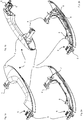
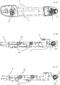
- FIG. 1 a motor vehicle door handle 1 according to a first embodiment of the invention is shown.
- the handle 1 has an upper shell component 2 and a lower shell component 3, which are connected when the handle is assembled in order to form the handle of the motor vehicle door handle 1.
- Mechanical coupling lugs 4 and 5 are also formed on the motor vehicle door handle 1. These mechanical coupling lugs 4 and 5 protrude during the assembly of the motor vehicle door handle 1 through recesses in a vehicle door panel and are coupled to a handle carrier on the inside of the vehicle door panel, so that the motor vehicle door handle 1 is mounted on the door and coupled for the mechanical actuation of vehicle-side locking components.
- a plug connector 6 is received, to which reference is made in detail below.
- Figure 2a shows the handle from the Figures 1a and 1b , wherein the shell component 2 is removed. It is in this representation It can be clearly seen that the shell components 2 and 3 delimit a cavity in which further components are accommodated.
- the potting compound 7 is shown, which fills the tub-shaped interior of the shell component 3. This potting compound is poured into the shell component 3 in liquid form in order to protectively surround the components located therein, in particular the carrier 8 and a circuit board 9 with electrical components located thereon. After curing, the potting compound 7 secures the components arranged in the shell component 3 against the effects of the weather and mechanical damage, and locks them in their position.
- a section of the carrier 8 that protrudes from the potting compound 7 can also already be seen.
- the visible section of the carrier 8 overlaps a wall of the shell component 3 with an angled section. In this way it is possible to make the wall for the potting in the shell component 3 higher, since the carrier 8 overlaps the wall by means of angled sections.
- FIG 2b was made from the representation of the Figure 2a the potting compound 7 is removed so that the components arranged in the shell component 3 are visible.
- the carrier 8 with a plate 9 arranged thereon is received in the shell component 3.
- the carrier 8 is supported on the inside of the shell component 3 on its walls, so that the carrier 8 is fixed in its position in the shell component 3.
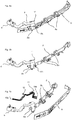
- Figures 3a, 3b and 3c show to the Figures 1a, 2a, 2b Corresponding representations, but in a different view.
- the motor vehicle door handle 1 is shown in a closed and fully assembled form, that is, with the shell component 2.
- the shell component 2 is removed so that the lower shell component 3 is exposed.
- the interior of the shell component 3 is again filled with the potting compound 7, the carrier 8 protruding in sections from the potting compound 7 and a The wall of the shell component 3 engages over and extends to the connector 6, with which it is integrally formed.
- Figure 3c shows this view, but without the potting compound 7.
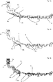
- the Figure 4a shows the carrier 8 in isolation, which is made from an injection-molded material and has an integrally molded plug connector 6.
- the circuit board 9 is held with holding means 8 a which are formed integrally with the carrier 8.
- electrical lines 10 extend from the plug connector 6 to the circuit board 9, with sections 10b protruding from the carrier 8 in the region of the circuit board and being guided through recesses in the circuit board 9. There they are galvanically connected to corresponding contacts on the bushings in order to make contact with the circuit board 9.
- sections 10a protrude in the connector for making contact.
- the carrier 8 is shown with the integrally molded plug connector 6, and the electrical lines 10 have been moved out of the interior of the carrier 8 for clarity.
- the lines 10 are designed as stamped and bent electrical sheets which run at a distance from one another and which reproduce the outer shape of the injection-molded carrier 8.
- the electrical lines 10 in their punched and bent shape have the same angles that allow the carrier 8 to be sunk in sections into the shell component 3 and to overlap it in the area of its wall, so that the molded connector 6 is in the mechanical coupling approach 5 can be included.
- one of the conductor tracks of the electrical lines 10 does not extend from the circuit board to the plug connector 6 is guided, but is coupled with a leaf spring 11 in a section between the connector 6 and the circuit board 9.
- This leaf spring is guided to the outside on the upper side of the carrier 8 and contacts the inside of the shell component 2 there when this is placed to close the handle.
- the inside of the shell component 2 which can in particular have a chrome plating, is thus coupled to the circuit board 9 by the electrical lines 10.
- the electrical lines 10 are formed by punching and bending as a self-supporting plurality of spaced apart and parallel conductor paths.
- This arrangement of conductors can be arranged in an injection mold in which the carrier 8 is formed with the connector 6 by overmolding, the electrical lines 10 with the sections 10a, 10b protruding from the tool in the area of the connector 6 and in the area of the circuit board and not be overmolded.
- the lines can be held in correct alignment with one another by non-conductive spacers.
- the electrical lines 10 can also be connected by conductive spacers prior to the overmolding process, which spacers are separated by a suitable tool after the overmolding process.
- Figures 5a, 5b and 5c correspond to the representations 4a and 4b, but show the carrier 8 and the circuit board 9 from a view from above.
- Figure 5c the carrier 8 with its injection-molded material is shown partially transparent, so that the course of the electrical contacts 10 through the injection-molded material from the plug connector 6 to the side of the circuit board is shown in a comprehensible manner.
- FIGS. 6a, 6b and 6c show the enlargements of the carrier section and the associated electrical lines in the area in which the electrical lines 10 extend through the carrier 8.
- Figure 6a shows the insulated electrical lines 10 with the coupled leaf spring 11, as they are designed to be received in the carrier 8.
- Contact connections 10a, 10b are formed on the ends, which on the one hand lead out of the injection molded part of the carrier 8 in the connector 6 for contacting and on the other end protrude out of the carrier 8 in order to contact the circuit board 9.
- Figure 6c shows the carrier 8 with cast-in electrical lines 10, the electrical lines 10 being shown in dashed lines in the areas that are enclosed by the material of the carrier 8. The course of the electrical lines in the injection molded body can be seen in this illustration. In this illustration, it cannot be readily seen that the connector 6 is designed as a hollow body with an interior space free for receiving a complementary connector, so that the connections 10a of the electrical lines 10 are exposed in the interior of the connector 6 so that they can be contacted.
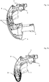
- the Figure 7a shows, like the sectional view in Figure 7b the handle according to the first embodiment with the shell component 2 removed in order to show the arrangement of the carrier 8 and the integrally formed plug connector 6 in the handle. It can be seen that the plug connector 6 is pushed laterally into a recess of the handle, in particular in a free space of the mechanical coupling part 5, and is available there for plug-in contacting.
- the support lugs 8b are supported on the inside on the wall of the shell component 3 in order to ensure a secure position of the carrier in the shell component 3 until the potting of the components in the shell component 3 has taken place.
- FIGS. 8a, 8b and 8c finally show the first embodiment according to the invention in a further view, which shows the mounted handle in FIG Figure 8a shows.
- the Figure 8b shows the carrier 8 with an integrally molded connector 6, the exposed contact sections 10a in the connector 6 being visible in this illustration.
- Figure 8b shows the carrier with the circuit board clipped onto it.
- the Figure 8c finally shows the carrier without the circuit board clipped on.
Landscapes
- Engineering & Computer Science (AREA)
- Microelectronics & Electronic Packaging (AREA)
- Mechanical Engineering (AREA)
- Manufacturing & Machinery (AREA)
- Lock And Its Accessories (AREA)
Claims (9)
- Poignée de porte de véhicule automobile (1) avec un boîtier de poignée, sachant que le boîtier de poignée est composé d'au moins deux composants de coque (2, 3), avec au moins une platine (9), laquelle est équipée de composants électroniques et est logée dans le boîtier de poignée,avec au moins un connecteur (6), lequel est disposé pour mettre en contact la platine (9) en dehors du boîtier, sachant que le connecteur (6) comporte une pluralité de contacts (10a), lesquels sont couplés à des conduits électriques, qui s'étendent dans le boîtier et jusqu'à la platine (9), sachant quela platine (9) est disposée et fixée sur un support (8) dans le boîtier de poignée, sachant que le support (8) est constitué en une pièce avec le connecteur (6) sous la forme d'une pièce moulée par injection et sachant que les conduits électriques dans le support (8) sont enrobés par extrusion en tant que conducteurs métalliques (10) et qu'au moins plusieurs des conducteurs métalliques (10) à proximité du connecteur (6) et de la platine (9) font saillie de la pièce moulée par injection pour la mise en contactcaractérisé en ce quele support (8) comporte un logement (8a) pour la platine (9), lequel maintient la platine sur le support avec des moyens de pinçage et d'encliquetage.
- Poignée de porte de véhicule automobile selon la revendication 1, sachant que les conduits électriques (10) sont formés sous la forme d'une structure métallique estampée et pliée avec au moins deux chemins de conducteurs passant à distance l'un de l'autre.
- Poignée de porte de véhicule automobile selon l'une quelconque des revendications précédentes, sachant que la platine (9) comporte une pluralité d'ouvertures continues, lesquelles logent et mettent en contact les conducteurs métalliques (10b) dépassant du support.
- Poignée de porte de véhicule automobile selon l'une quelconque des revendications précédentes, sachant que le support (8) comporte des saillies de soutien (8b), lesquelles s'appuient sur la face intérieure d'au moins un des composants de coque (3) et fixent le support (8) avec la platine (9) dans le composant de coque (3).
- Poignée de porte de véhicule automobile selon l'une quelconque des revendications précédentes, sachant qu'au moins un des conducteurs métalliques (10b) fait saillie du support (8) dans une section entre le connecteur (6) et la platine (9) et fait contact avec une face intérieure d'un des composants de coque (2, 3) .
- Poignée de porte de véhicule automobile selon la revendication 5, sachant qu'un ressort à lame (11) est galvaniquement couplé au conducteur métallique pour la mise en contact de la face intérieure d'un des composants de coque.
- Poignée de porte de véhicule automobile selon l'une quelconque des revendications précédentes, sachant que le support (8) comporte une section coudée dans une section entre le connecteur (6) et la platine (9) de telle manière que le support (8) vient en prise avec la section coudée sur une paroi d'un composant de coque (3) et plonge dans le composant de coque (3) depuis un côté de la paroi.
- Poignée de porte de véhicule automobile selon l'une quelconque des revendications précédentes, sachant qu'un des composants de coque (3) comporte un logement pour le connecteur (6), sachant que le connecteur (6) est encliqueté ou pincé dans le logement de connecteur, lorsque le support (8) est inséré dans le boîtier.
- Poignée de porte de véhicule automobile selon l'une quelconque des revendications précédentes, sachant que le connecteur (6) s'étend dans un embout de boîtier (5) pour le couplage mécanique de la poignée de porte de véhicule automobile avec un support de poignée dans un véhicule automobile.
Applications Claiming Priority (2)
| Application Number | Priority Date | Filing Date | Title |
|---|---|---|---|
| DE102017130876.8A DE102017130876A1 (de) | 2017-12-21 | 2017-12-21 | Fahrzeugtürgriff |
| PCT/EP2018/084119 WO2019121090A1 (fr) | 2017-12-21 | 2018-12-10 | Poignée de portière de véhicule |
Publications (2)
| Publication Number | Publication Date |
|---|---|
| EP3728772A1 EP3728772A1 (fr) | 2020-10-28 |
| EP3728772B1 true EP3728772B1 (fr) | 2021-09-15 |
Family
ID=64746531
Family Applications (1)
| Application Number | Title | Priority Date | Filing Date |
|---|---|---|---|
| EP18822294.7A Active EP3728772B1 (fr) | 2017-12-21 | 2018-12-10 | Poignée de portière de véhicule |
Country Status (5)
| Country | Link |
|---|---|
| US (1) | US20210076514A1 (fr) |
| EP (1) | EP3728772B1 (fr) |
| CN (1) | CN111406140A (fr) |
| DE (1) | DE102017130876A1 (fr) |
| WO (1) | WO2019121090A1 (fr) |
Families Citing this family (3)
| Publication number | Priority date | Publication date | Assignee | Title |
|---|---|---|---|---|
| DE102018113268A1 (de) * | 2018-06-04 | 2019-12-05 | Huf Hülsbeck & Fürst Gmbh & Co. Kg | Türgriff und Fertigungsverfahren hierzu |
| USD950354S1 (en) * | 2019-05-15 | 2022-05-03 | Mf Ip Holding, Llc | Handle |
| DE102021111342A1 (de) | 2021-05-03 | 2022-11-03 | Kiekert Aktiengesellschaft | Kraftfahrzeug-Außenhautbauteil |
Family Cites Families (6)
| Publication number | Priority date | Publication date | Assignee | Title |
|---|---|---|---|---|
| JP4535010B2 (ja) * | 2006-03-16 | 2010-09-01 | アイシン精機株式会社 | 車両用のドアハンドル |
| JP5078408B2 (ja) * | 2007-03-30 | 2012-11-21 | 株式会社ホンダロック | 車両用アウトハンドル装置 |
| CN201756837U (zh) * | 2010-02-11 | 2011-03-09 | 上海海拉电子有限公司 | 一种汽车门把手 |
| JP5022483B2 (ja) * | 2010-07-26 | 2012-09-12 | アイシン精機株式会社 | 車両用ドアハンドル装置 |
| DE102011056818A1 (de) | 2011-12-21 | 2013-06-27 | Huf Hülsbeck & Fürst Gmbh & Co. Kg | Kraftfahrzeugtürgriff mit vergossener Elektronikkomponente |
| DE102016010494A1 (de) * | 2016-08-31 | 2018-03-01 | Huf Hülsbeck & Fürst Gmbh & Co. Kg | Elektronikmodul für eine Kraftfahrzeugtürgriffanordnung |
-
2017
- 2017-12-21 DE DE102017130876.8A patent/DE102017130876A1/de active Pending
-
2018
- 2018-12-10 CN CN201880074916.8A patent/CN111406140A/zh active Pending
- 2018-12-10 WO PCT/EP2018/084119 patent/WO2019121090A1/fr not_active Ceased
- 2018-12-10 US US16/772,182 patent/US20210076514A1/en not_active Abandoned
- 2018-12-10 EP EP18822294.7A patent/EP3728772B1/fr active Active
Also Published As
| Publication number | Publication date |
|---|---|
| DE102017130876A1 (de) | 2019-06-27 |
| EP3728772A1 (fr) | 2020-10-28 |
| US20210076514A1 (en) | 2021-03-11 |
| WO2019121090A1 (fr) | 2019-06-27 |
| CN111406140A (zh) | 2020-07-10 |
Similar Documents
| Publication | Publication Date | Title |
|---|---|---|
| EP2567426B1 (fr) | Connexion de module électrique d'un véhicule à moteur | |
| EP3507437B1 (fr) | Module électronique pour système de poignée de porte de véhicule automobile | |
| EP2567429B1 (fr) | Connexion de module électrique d'un véhicule à moteur | |
| EP3728772B1 (fr) | Poignée de portière de véhicule | |
| DE102004019898B4 (de) | Wasserdichter Verbinder | |
| EP3679211B1 (fr) | Ensemble formant poignée de portière de véhicule automobile intégrant un système électronique scellé | |
| EP3507862B1 (fr) | Dispositif de poignée de porte de véhicule à moteur comprenant un espace de montage électronique étanche | |
| EP1608994B1 (fr) | Ensemble capteur d'un systeme d'aide au stationnement | |
| EP3309904B1 (fr) | Logement de raccordement d'au moins un toron de câbles d'un câble | |
| EP2787578B1 (fr) | Entraînement de porte comportant un système électrique | |
| EP4430707A1 (fr) | Appareil de support de contact, dispositif de connexion, actionneur, insert de connecteur enfichable et procédé d'installation, et système de connexion de câble | |
| DE102009000258A1 (de) | Anschlussgehäuse zum Einbau in eine Fahrzeugkarosserie | |
| EP2449195B1 (fr) | Serrure de véhicule à moteur comprenant des éléments composants mécaniques et électriques, à moteur électrique et/ou électronique | |
| DE10348045A1 (de) | Elektrischer Verbinder für flexiblen Flachleiter und Schaltvorrichtung | |
| BE1025721B1 (de) | Elektronikgerät mit einem Gehäusekörper zur Bauteileinhausung und einer Anschlusseinrichtung | |
| EP3507439B1 (fr) | Ensemble poignée de porte de véhicule à moteur doté d'un connecteur fixé par complémentarité de forme | |
| DE102005042248B3 (de) | Formbauteil für ein Kraftfahrzeug und Verfahren zu dessen Herstellung | |
| DE102016010561A1 (de) | Kraftfahrzeugtürgriffanordnung mit Antenne | |
| DE102015121832A1 (de) | Steckverbinder zur elektrischen Direktkontaktierung und Steckverbindung | |
| DE102004023189A1 (de) | Lösbare elektrische Kontaktierung dreidimensionaler spritzgegossener Schaltungsträger | |
| EP3103315B1 (fr) | Appareil électrique et dispositif de liaison comportant un appareil électrique | |
| DE19817433A1 (de) | Elektrische Anschlußbaueinheit | |
| WO2019154709A1 (fr) | Module de connexion pour connecter un conducteur électrique et dispositif comportant un tronçon de barrette conductrice externe et un module de connexion | |
| DE10213673A1 (de) | Verbindungselement | |
| DE102023124302A1 (de) | Kraftfahrzeug-technische Gehäuse |
Legal Events
| Date | Code | Title | Description |
|---|---|---|---|
| STAA | Information on the status of an ep patent application or granted ep patent |
Free format text: STATUS: UNKNOWN |
|
| STAA | Information on the status of an ep patent application or granted ep patent |
Free format text: STATUS: THE INTERNATIONAL PUBLICATION HAS BEEN MADE |
|
| PUAI | Public reference made under article 153(3) epc to a published international application that has entered the european phase |
Free format text: ORIGINAL CODE: 0009012 |
|
| STAA | Information on the status of an ep patent application or granted ep patent |
Free format text: STATUS: REQUEST FOR EXAMINATION WAS MADE |
|
| 17P | Request for examination filed |
Effective date: 20200403 |
|
| AK | Designated contracting states |
Kind code of ref document: A1 Designated state(s): AL AT BE BG CH CY CZ DE DK EE ES FI FR GB GR HR HU IE IS IT LI LT LU LV MC MK MT NL NO PL PT RO RS SE SI SK SM TR |
|
| AX | Request for extension of the european patent |
Extension state: BA ME |
|
| DAV | Request for validation of the european patent (deleted) | ||
| DAX | Request for extension of the european patent (deleted) | ||
| GRAP | Despatch of communication of intention to grant a patent |
Free format text: ORIGINAL CODE: EPIDOSNIGR1 |
|
| STAA | Information on the status of an ep patent application or granted ep patent |
Free format text: STATUS: GRANT OF PATENT IS INTENDED |
|
| RIC1 | Information provided on ipc code assigned before grant |
Ipc: E05B 81/54 20140101ALN20210628BHEP Ipc: E05B 17/00 20060101ALI20210628BHEP Ipc: E05B 85/10 20140101ALI20210628BHEP Ipc: E05B 81/76 20140101ALI20210628BHEP Ipc: E05B 85/16 20140101AFI20210628BHEP |
|
| GRAS | Grant fee paid |
Free format text: ORIGINAL CODE: EPIDOSNIGR3 |
|
| GRAA | (expected) grant |
Free format text: ORIGINAL CODE: 0009210 |
|
| STAA | Information on the status of an ep patent application or granted ep patent |
Free format text: STATUS: THE PATENT HAS BEEN GRANTED |
|
| INTG | Intention to grant announced |
Effective date: 20210727 |
|
| AK | Designated contracting states |
Kind code of ref document: B1 Designated state(s): AL AT BE BG CH CY CZ DE DK EE ES FI FR GB GR HR HU IE IS IT LI LT LU LV MC MK MT NL NO PL PT RO RS SE SI SK SM TR |
|
| REG | Reference to a national code |
Ref country code: CH Ref legal event code: EP |
|
| REG | Reference to a national code |
Ref country code: DE Ref legal event code: R096 Ref document number: 502018007123 Country of ref document: DE |
|
| REG | Reference to a national code |
Ref country code: IE Ref legal event code: FG4D Free format text: LANGUAGE OF EP DOCUMENT: GERMAN |
|
| REG | Reference to a national code |
Ref country code: AT Ref legal event code: REF Ref document number: 1430648 Country of ref document: AT Kind code of ref document: T Effective date: 20211015 |
|
| REG | Reference to a national code |
Ref country code: LT Ref legal event code: MG9D |
|
| REG | Reference to a national code |
Ref country code: NL Ref legal event code: MP Effective date: 20210915 |
|
| PG25 | Lapsed in a contracting state [announced via postgrant information from national office to epo] |
Ref country code: RS Free format text: LAPSE BECAUSE OF FAILURE TO SUBMIT A TRANSLATION OF THE DESCRIPTION OR TO PAY THE FEE WITHIN THE PRESCRIBED TIME-LIMIT Effective date: 20210915 Ref country code: SE Free format text: LAPSE BECAUSE OF FAILURE TO SUBMIT A TRANSLATION OF THE DESCRIPTION OR TO PAY THE FEE WITHIN THE PRESCRIBED TIME-LIMIT Effective date: 20210915 Ref country code: FI Free format text: LAPSE BECAUSE OF FAILURE TO SUBMIT A TRANSLATION OF THE DESCRIPTION OR TO PAY THE FEE WITHIN THE PRESCRIBED TIME-LIMIT Effective date: 20210915 Ref country code: BG Free format text: LAPSE BECAUSE OF FAILURE TO SUBMIT A TRANSLATION OF THE DESCRIPTION OR TO PAY THE FEE WITHIN THE PRESCRIBED TIME-LIMIT Effective date: 20211215 Ref country code: LT Free format text: LAPSE BECAUSE OF FAILURE TO SUBMIT A TRANSLATION OF THE DESCRIPTION OR TO PAY THE FEE WITHIN THE PRESCRIBED TIME-LIMIT Effective date: 20210915 Ref country code: HR Free format text: LAPSE BECAUSE OF FAILURE TO SUBMIT A TRANSLATION OF THE DESCRIPTION OR TO PAY THE FEE WITHIN THE PRESCRIBED TIME-LIMIT Effective date: 20210915 Ref country code: NO Free format text: LAPSE BECAUSE OF FAILURE TO SUBMIT A TRANSLATION OF THE DESCRIPTION OR TO PAY THE FEE WITHIN THE PRESCRIBED TIME-LIMIT Effective date: 20211215 |
|
| PG25 | Lapsed in a contracting state [announced via postgrant information from national office to epo] |
Ref country code: LV Free format text: LAPSE BECAUSE OF FAILURE TO SUBMIT A TRANSLATION OF THE DESCRIPTION OR TO PAY THE FEE WITHIN THE PRESCRIBED TIME-LIMIT Effective date: 20210915 Ref country code: GR Free format text: LAPSE BECAUSE OF FAILURE TO SUBMIT A TRANSLATION OF THE DESCRIPTION OR TO PAY THE FEE WITHIN THE PRESCRIBED TIME-LIMIT Effective date: 20211216 |
|
| PG25 | Lapsed in a contracting state [announced via postgrant information from national office to epo] |
Ref country code: IS Free format text: LAPSE BECAUSE OF FAILURE TO SUBMIT A TRANSLATION OF THE DESCRIPTION OR TO PAY THE FEE WITHIN THE PRESCRIBED TIME-LIMIT Effective date: 20220115 Ref country code: SM Free format text: LAPSE BECAUSE OF FAILURE TO SUBMIT A TRANSLATION OF THE DESCRIPTION OR TO PAY THE FEE WITHIN THE PRESCRIBED TIME-LIMIT Effective date: 20210915 Ref country code: SK Free format text: LAPSE BECAUSE OF FAILURE TO SUBMIT A TRANSLATION OF THE DESCRIPTION OR TO PAY THE FEE WITHIN THE PRESCRIBED TIME-LIMIT Effective date: 20210915 Ref country code: RO Free format text: LAPSE BECAUSE OF FAILURE TO SUBMIT A TRANSLATION OF THE DESCRIPTION OR TO PAY THE FEE WITHIN THE PRESCRIBED TIME-LIMIT Effective date: 20210915 Ref country code: PT Free format text: LAPSE BECAUSE OF FAILURE TO SUBMIT A TRANSLATION OF THE DESCRIPTION OR TO PAY THE FEE WITHIN THE PRESCRIBED TIME-LIMIT Effective date: 20220117 Ref country code: PL Free format text: LAPSE BECAUSE OF FAILURE TO SUBMIT A TRANSLATION OF THE DESCRIPTION OR TO PAY THE FEE WITHIN THE PRESCRIBED TIME-LIMIT Effective date: 20210915 Ref country code: NL Free format text: LAPSE BECAUSE OF FAILURE TO SUBMIT A TRANSLATION OF THE DESCRIPTION OR TO PAY THE FEE WITHIN THE PRESCRIBED TIME-LIMIT Effective date: 20210915 Ref country code: ES Free format text: LAPSE BECAUSE OF FAILURE TO SUBMIT A TRANSLATION OF THE DESCRIPTION OR TO PAY THE FEE WITHIN THE PRESCRIBED TIME-LIMIT Effective date: 20210915 Ref country code: EE Free format text: LAPSE BECAUSE OF FAILURE TO SUBMIT A TRANSLATION OF THE DESCRIPTION OR TO PAY THE FEE WITHIN THE PRESCRIBED TIME-LIMIT Effective date: 20210915 Ref country code: CZ Free format text: LAPSE BECAUSE OF FAILURE TO SUBMIT A TRANSLATION OF THE DESCRIPTION OR TO PAY THE FEE WITHIN THE PRESCRIBED TIME-LIMIT Effective date: 20210915 Ref country code: AL Free format text: LAPSE BECAUSE OF FAILURE TO SUBMIT A TRANSLATION OF THE DESCRIPTION OR TO PAY THE FEE WITHIN THE PRESCRIBED TIME-LIMIT Effective date: 20210915 |
|
| REG | Reference to a national code |
Ref country code: DE Ref legal event code: R097 Ref document number: 502018007123 Country of ref document: DE |
|
| PLBE | No opposition filed within time limit |
Free format text: ORIGINAL CODE: 0009261 |
|
| STAA | Information on the status of an ep patent application or granted ep patent |
Free format text: STATUS: NO OPPOSITION FILED WITHIN TIME LIMIT |
|
| PG25 | Lapsed in a contracting state [announced via postgrant information from national office to epo] |
Ref country code: MC Free format text: LAPSE BECAUSE OF FAILURE TO SUBMIT A TRANSLATION OF THE DESCRIPTION OR TO PAY THE FEE WITHIN THE PRESCRIBED TIME-LIMIT Effective date: 20210915 Ref country code: DK Free format text: LAPSE BECAUSE OF FAILURE TO SUBMIT A TRANSLATION OF THE DESCRIPTION OR TO PAY THE FEE WITHIN THE PRESCRIBED TIME-LIMIT Effective date: 20210915 |
|
| REG | Reference to a national code |
Ref country code: CH Ref legal event code: PL |
|
| 26N | No opposition filed |
Effective date: 20220616 |
|
| REG | Reference to a national code |
Ref country code: BE Ref legal event code: MM Effective date: 20211231 |
|
| PG25 | Lapsed in a contracting state [announced via postgrant information from national office to epo] |
Ref country code: LU Free format text: LAPSE BECAUSE OF NON-PAYMENT OF DUE FEES Effective date: 20211210 Ref country code: IE Free format text: LAPSE BECAUSE OF NON-PAYMENT OF DUE FEES Effective date: 20211210 |
|
| PG25 | Lapsed in a contracting state [announced via postgrant information from national office to epo] |
Ref country code: FR Free format text: LAPSE BECAUSE OF NON-PAYMENT OF DUE FEES Effective date: 20211231 Ref country code: BE Free format text: LAPSE BECAUSE OF NON-PAYMENT OF DUE FEES Effective date: 20211231 |
|
| PG25 | Lapsed in a contracting state [announced via postgrant information from national office to epo] |
Ref country code: LI Free format text: LAPSE BECAUSE OF NON-PAYMENT OF DUE FEES Effective date: 20211231 Ref country code: CH Free format text: LAPSE BECAUSE OF NON-PAYMENT OF DUE FEES Effective date: 20211231 |
|
| PG25 | Lapsed in a contracting state [announced via postgrant information from national office to epo] |
Ref country code: IT Free format text: LAPSE BECAUSE OF FAILURE TO SUBMIT A TRANSLATION OF THE DESCRIPTION OR TO PAY THE FEE WITHIN THE PRESCRIBED TIME-LIMIT Effective date: 20210915 |
|
| P01 | Opt-out of the competence of the unified patent court (upc) registered |
Effective date: 20230505 |
|
| PG25 | Lapsed in a contracting state [announced via postgrant information from national office to epo] |
Ref country code: CY Free format text: LAPSE BECAUSE OF FAILURE TO SUBMIT A TRANSLATION OF THE DESCRIPTION OR TO PAY THE FEE WITHIN THE PRESCRIBED TIME-LIMIT Effective date: 20210915 |
|
| PG25 | Lapsed in a contracting state [announced via postgrant information from national office to epo] |
Ref country code: HU Free format text: LAPSE BECAUSE OF FAILURE TO SUBMIT A TRANSLATION OF THE DESCRIPTION OR TO PAY THE FEE WITHIN THE PRESCRIBED TIME-LIMIT; INVALID AB INITIO Effective date: 20181210 |
|
| GBPC | Gb: european patent ceased through non-payment of renewal fee |
Effective date: 20221210 |
|
| PG25 | Lapsed in a contracting state [announced via postgrant information from national office to epo] |
Ref country code: SI Free format text: LAPSE BECAUSE OF FAILURE TO SUBMIT A TRANSLATION OF THE DESCRIPTION OR TO PAY THE FEE WITHIN THE PRESCRIBED TIME-LIMIT Effective date: 20210915 |
|
| PG25 | Lapsed in a contracting state [announced via postgrant information from national office to epo] |
Ref country code: GB Free format text: LAPSE BECAUSE OF NON-PAYMENT OF DUE FEES Effective date: 20221210 |
|
| PG25 | Lapsed in a contracting state [announced via postgrant information from national office to epo] |
Ref country code: MK Free format text: LAPSE BECAUSE OF FAILURE TO SUBMIT A TRANSLATION OF THE DESCRIPTION OR TO PAY THE FEE WITHIN THE PRESCRIBED TIME-LIMIT Effective date: 20210915 |
|
| PG25 | Lapsed in a contracting state [announced via postgrant information from national office to epo] |
Ref country code: MT Free format text: LAPSE BECAUSE OF FAILURE TO SUBMIT A TRANSLATION OF THE DESCRIPTION OR TO PAY THE FEE WITHIN THE PRESCRIBED TIME-LIMIT Effective date: 20210915 |
|
| REG | Reference to a national code |
Ref country code: AT Ref legal event code: MM01 Ref document number: 1430648 Country of ref document: AT Kind code of ref document: T Effective date: 20231210 |
|
| PG25 | Lapsed in a contracting state [announced via postgrant information from national office to epo] |
Ref country code: AT Free format text: LAPSE BECAUSE OF NON-PAYMENT OF DUE FEES Effective date: 20231210 |
|
| PG25 | Lapsed in a contracting state [announced via postgrant information from national office to epo] |
Ref country code: TR Free format text: LAPSE BECAUSE OF FAILURE TO SUBMIT A TRANSLATION OF THE DESCRIPTION OR TO PAY THE FEE WITHIN THE PRESCRIBED TIME-LIMIT Effective date: 20210915 |
|
| PGFP | Annual fee paid to national office [announced via postgrant information from national office to epo] |
Ref country code: DE Payment date: 20251222 Year of fee payment: 8 |
|
| PGFP | Annual fee paid to national office [announced via postgrant information from national office to epo] |
Ref country code: AT Payment date: 20260410 Year of fee payment: 5 |