EP3728800B1 - Kraftwerk - Google Patents
Kraftwerk Download PDFInfo
- Publication number
- EP3728800B1 EP3728800B1 EP18826986.4A EP18826986A EP3728800B1 EP 3728800 B1 EP3728800 B1 EP 3728800B1 EP 18826986 A EP18826986 A EP 18826986A EP 3728800 B1 EP3728800 B1 EP 3728800B1
- Authority
- EP
- European Patent Office
- Prior art keywords
- steam
- residual
- power plant
- feed water
- pressure
- Prior art date
- Legal status (The legal status is an assumption and is not a legal conclusion. Google has not performed a legal analysis and makes no representation as to the accuracy of the status listed.)
- Active
Links
Images
Classifications
-
- F—MECHANICAL ENGINEERING; LIGHTING; HEATING; WEAPONS; BLASTING
- F01—MACHINES OR ENGINES IN GENERAL; ENGINE PLANTS IN GENERAL; STEAM ENGINES
- F01K—STEAM ENGINE PLANTS; STEAM ACCUMULATORS; ENGINE PLANTS NOT OTHERWISE PROVIDED FOR; ENGINES USING SPECIAL WORKING FLUIDS OR CYCLES
- F01K23/00—Plants characterised by more than one engine delivering power external to the plant, the engines being driven by different fluids
- F01K23/02—Plants characterised by more than one engine delivering power external to the plant, the engines being driven by different fluids the engine cycles being thermally coupled
- F01K23/06—Plants characterised by more than one engine delivering power external to the plant, the engines being driven by different fluids the engine cycles being thermally coupled combustion heat from one cycle heating the fluid in another cycle
- F01K23/10—Plants characterised by more than one engine delivering power external to the plant, the engines being driven by different fluids the engine cycles being thermally coupled combustion heat from one cycle heating the fluid in another cycle with exhaust fluid of one cycle heating the fluid in another cycle
-
- F—MECHANICAL ENGINEERING; LIGHTING; HEATING; WEAPONS; BLASTING
- F01—MACHINES OR ENGINES IN GENERAL; ENGINE PLANTS IN GENERAL; STEAM ENGINES
- F01D—NON-POSITIVE DISPLACEMENT MACHINES OR ENGINES, e.g. STEAM TURBINES
- F01D15/00—Adaptations of machines or engines for special use; Combinations of engines with devices driven thereby
- F01D15/10—Adaptations for driving, or combinations with, electric generators
-
- F—MECHANICAL ENGINEERING; LIGHTING; HEATING; WEAPONS; BLASTING
- F01—MACHINES OR ENGINES IN GENERAL; ENGINE PLANTS IN GENERAL; STEAM ENGINES
- F01K—STEAM ENGINE PLANTS; STEAM ACCUMULATORS; ENGINE PLANTS NOT OTHERWISE PROVIDED FOR; ENGINES USING SPECIAL WORKING FLUIDS OR CYCLES
- F01K11/00—Plants characterised by the engines being structurally combined with boilers or condensers
-
- F—MECHANICAL ENGINEERING; LIGHTING; HEATING; WEAPONS; BLASTING
- F01—MACHINES OR ENGINES IN GENERAL; ENGINE PLANTS IN GENERAL; STEAM ENGINES
- F01K—STEAM ENGINE PLANTS; STEAM ACCUMULATORS; ENGINE PLANTS NOT OTHERWISE PROVIDED FOR; ENGINES USING SPECIAL WORKING FLUIDS OR CYCLES
- F01K17/00—Using steam or condensate extracted or exhausted from steam engine plant
- F01K17/04—Using steam or condensate extracted or exhausted from steam engine plant for specific purposes other than heating
-
- F—MECHANICAL ENGINEERING; LIGHTING; HEATING; WEAPONS; BLASTING
- F01—MACHINES OR ENGINES IN GENERAL; ENGINE PLANTS IN GENERAL; STEAM ENGINES
- F01K—STEAM ENGINE PLANTS; STEAM ACCUMULATORS; ENGINE PLANTS NOT OTHERWISE PROVIDED FOR; ENGINES USING SPECIAL WORKING FLUIDS OR CYCLES
- F01K19/00—Regenerating or otherwise treating steam exhausted from steam engine plant
-
- F—MECHANICAL ENGINEERING; LIGHTING; HEATING; WEAPONS; BLASTING
- F01—MACHINES OR ENGINES IN GENERAL; ENGINE PLANTS IN GENERAL; STEAM ENGINES
- F01K—STEAM ENGINE PLANTS; STEAM ACCUMULATORS; ENGINE PLANTS NOT OTHERWISE PROVIDED FOR; ENGINES USING SPECIAL WORKING FLUIDS OR CYCLES
- F01K23/00—Plants characterised by more than one engine delivering power external to the plant, the engines being driven by different fluids
- F01K23/02—Plants characterised by more than one engine delivering power external to the plant, the engines being driven by different fluids the engine cycles being thermally coupled
- F01K23/06—Plants characterised by more than one engine delivering power external to the plant, the engines being driven by different fluids the engine cycles being thermally coupled combustion heat from one cycle heating the fluid in another cycle
- F01K23/10—Plants characterised by more than one engine delivering power external to the plant, the engines being driven by different fluids the engine cycles being thermally coupled combustion heat from one cycle heating the fluid in another cycle with exhaust fluid of one cycle heating the fluid in another cycle
- F01K23/101—Regulating means specially adapted therefor
-
- F—MECHANICAL ENGINEERING; LIGHTING; HEATING; WEAPONS; BLASTING
- F01—MACHINES OR ENGINES IN GENERAL; ENGINE PLANTS IN GENERAL; STEAM ENGINES
- F01K—STEAM ENGINE PLANTS; STEAM ACCUMULATORS; ENGINE PLANTS NOT OTHERWISE PROVIDED FOR; ENGINES USING SPECIAL WORKING FLUIDS OR CYCLES
- F01K7/00—Steam engine plants characterised by the use of specific types of engine; Plants or engines characterised by their use of special steam systems, cycles or processes; Control means specially adapted for such systems, cycles or processes; Use of withdrawn or exhaust steam for feed-water heating
- F01K7/34—Steam engine plants characterised by the use of specific types of engine; Plants or engines characterised by their use of special steam systems, cycles or processes; Control means specially adapted for such systems, cycles or processes; Use of withdrawn or exhaust steam for feed-water heating the engines being of extraction or non-condensing type; Use of steam for feed-water heating
-
- F—MECHANICAL ENGINEERING; LIGHTING; HEATING; WEAPONS; BLASTING
- F22—STEAM GENERATION
- F22D—PREHEATING, OR ACCUMULATING PREHEATED, FEED-WATER FOR STEAM GENERATION; FEED-WATER SUPPLY FOR STEAM GENERATION; CONTROLLING WATER LEVEL FOR STEAM GENERATION; AUXILIARY DEVICES FOR PROMOTING WATER CIRCULATION WITHIN STEAM BOILERS
- F22D5/00—Controlling water feed or water level; Automatic water feeding or water-level regulators
-
- F—MECHANICAL ENGINEERING; LIGHTING; HEATING; WEAPONS; BLASTING
- F01—MACHINES OR ENGINES IN GENERAL; ENGINE PLANTS IN GENERAL; STEAM ENGINES
- F01K—STEAM ENGINE PLANTS; STEAM ACCUMULATORS; ENGINE PLANTS NOT OTHERWISE PROVIDED FOR; ENGINES USING SPECIAL WORKING FLUIDS OR CYCLES
- F01K23/00—Plants characterised by more than one engine delivering power external to the plant, the engines being driven by different fluids
- F01K23/02—Plants characterised by more than one engine delivering power external to the plant, the engines being driven by different fluids the engine cycles being thermally coupled
- F01K23/06—Plants characterised by more than one engine delivering power external to the plant, the engines being driven by different fluids the engine cycles being thermally coupled combustion heat from one cycle heating the fluid in another cycle
- F01K23/10—Plants characterised by more than one engine delivering power external to the plant, the engines being driven by different fluids the engine cycles being thermally coupled combustion heat from one cycle heating the fluid in another cycle with exhaust fluid of one cycle heating the fluid in another cycle
- F01K23/103—Plants characterised by more than one engine delivering power external to the plant, the engines being driven by different fluids the engine cycles being thermally coupled combustion heat from one cycle heating the fluid in another cycle with exhaust fluid of one cycle heating the fluid in another cycle with afterburner in exhaust boiler
-
- Y—GENERAL TAGGING OF NEW TECHNOLOGICAL DEVELOPMENTS; GENERAL TAGGING OF CROSS-SECTIONAL TECHNOLOGIES SPANNING OVER SEVERAL SECTIONS OF THE IPC; TECHNICAL SUBJECTS COVERED BY FORMER USPC CROSS-REFERENCE ART COLLECTIONS [XRACs] AND DIGESTS
- Y02—TECHNOLOGIES OR APPLICATIONS FOR MITIGATION OR ADAPTATION AGAINST CLIMATE CHANGE
- Y02E—REDUCTION OF GREENHOUSE GAS [GHG] EMISSIONS, RELATED TO ENERGY GENERATION, TRANSMISSION OR DISTRIBUTION
- Y02E20/00—Combustion technologies with mitigation potential
- Y02E20/14—Combined heat and power generation [CHP]
-
- Y—GENERAL TAGGING OF NEW TECHNOLOGICAL DEVELOPMENTS; GENERAL TAGGING OF CROSS-SECTIONAL TECHNOLOGIES SPANNING OVER SEVERAL SECTIONS OF THE IPC; TECHNICAL SUBJECTS COVERED BY FORMER USPC CROSS-REFERENCE ART COLLECTIONS [XRACs] AND DIGESTS
- Y02—TECHNOLOGIES OR APPLICATIONS FOR MITIGATION OR ADAPTATION AGAINST CLIMATE CHANGE
- Y02E—REDUCTION OF GREENHOUSE GAS [GHG] EMISSIONS, RELATED TO ENERGY GENERATION, TRANSMISSION OR DISTRIBUTION
- Y02E20/00—Combustion technologies with mitigation potential
- Y02E20/16—Combined cycle power plant [CCPP], or combined cycle gas turbine [CCGT]
-
- Y—GENERAL TAGGING OF NEW TECHNOLOGICAL DEVELOPMENTS; GENERAL TAGGING OF CROSS-SECTIONAL TECHNOLOGIES SPANNING OVER SEVERAL SECTIONS OF THE IPC; TECHNICAL SUBJECTS COVERED BY FORMER USPC CROSS-REFERENCE ART COLLECTIONS [XRACs] AND DIGESTS
- Y02—TECHNOLOGIES OR APPLICATIONS FOR MITIGATION OR ADAPTATION AGAINST CLIMATE CHANGE
- Y02P—CLIMATE CHANGE MITIGATION TECHNOLOGIES IN THE PRODUCTION OR PROCESSING OF GOODS
- Y02P80/00—Climate change mitigation technologies for sector-wide applications
- Y02P80/10—Efficient use of energy, e.g. using compressed air or pressurized fluid as energy carrier
- Y02P80/15—On-site combined power, heat or cool generation or distribution, e.g. combined heat and power [CHP] supply
Definitions
- the invention relates to a power plant for generating electrical energy and extraction steam (gas and steam power plant).
- the power plant according to the invention is provided with a gas turbine and works according to the combined heat and power system.
- an amount of extraction steam is maximized.
- fuel can be saved in the gas turbine or an additional firing system, since the required process steam is provided using less energy. In this way, both the operating costs of the power plant and its CO2 emissions can be reduced.
- Gas and steam power plants with combined heat and power generation are known from the prior art. For example, from the U.S. 5,044,163A such a power plant. However, no removal of process steam is planned for this power plant. Power plants in which process steam can be extracted are also known from the prior art. Typically, such power plants are built specifically for industrial consumers of electricity and heat. Heat is given off in the form of process steam. Advantageously, the consumers have a continuous need for energy. Such power plants have a gas turbine whose flue gas is used to evaporate feed water, with the live steam thus generated driving a steam turbine. After passing through the steam turbine, the residual steam can be extracted from the power plant as process steam and can be used for other processes.
- the task is thus solved by a power plant for generating electrical energy and process steam.
- the power plant includes a gas turbine, a steam turbine and a heat recovery steam generator.
- the waste heat steam generator is designed in at least one stage and can, in particular, also be designed in multiple stages.
- the gas turbine is used to drive a first generator to generate electrical energy by burning a fuel to form flue gas.
- the steam turbine is used to drive a second generator.
- the steam turbine has at least a first stage, in particular a high-pressure stage, in order to convert live steam into residual steam. In this way, energy is extracted from the live steam to drive the generator.
- the residual steam represents at least part of the process steam that can be extracted from the power plant.
- the heat recovery steam generator is used to generate live steam from fresh water using waste heat from the flue gas.
- the fresh water can either be supplied to the power plant, in particular to compensate for process steam that has been removed, and/or can be obtained from part of the residual steam by condensing it.
- the heat recovery steam generator comprises a plurality of heat exchangers in order to convert the fresh water into the fresh steam. Provision is made for the residual steam to have a residual steam pressure which is lower than a live steam pressure of the live steam. The live steam thus has more energy than the residual steam, which can be used in the steam turbine to drive the second generator.
- the steam turbine can only have the first stage, in particular the high-pressure stage. In this case, the steam turbine is designed in one stage. Alternatively, the steam turbine can also have an additional second stage, in particular a low-pressure stage. In this case, the steam turbine is designed in two stages.
- the heat recovery steam generator has a preheater and an evaporator.
- the preheater is used to preheat the fresh water into feed water.
- the evaporator serves to evaporate the feed water into the live steam.
- the preheater and the evaporator each comprise a heat exchanger which is introduced into a flow of the flue gas.
- the evaporator is arranged at a hotter point in the flow of flue gas than the preheater.
- the feed water has a feed water pressure that is higher than the residual steam pressure.
- the feed water pressure is built up in particular by a pump unit, through which fresh water can be pumped through the preheater.
- the feed water pressure is particularly advantageously a pressure of between 50 bar and 150 bar, preferably between 80 bar and 120 bar, particularly around 100 bar.
- the residual vapor pressure is in particular a pressure between 1 bar and 10 bar, in particular between 3 bar and 7 bar, particularly preferably around 5 bar.
- the live-steam pressure at full load is in particular the feedwater pressure minus 2 bar to 5 bar pressure loss, and in part-load operation it is in particular a pressure of between 10 bar and 20 bar, in particular between 13 bar and 17 bar, particularly preferably around 15 bar.
- the power plant also has a throttle valve or several throttle valves in stages and preferably at least one water separator.
- the at least one throttle valve is designed to relieve part of the feed water.
- the throttle valve can either be designed to expand part of the feed water to the residual steam pressure, or alternatively to a driving steam pressure.
- additional steam is generated that has the same steam pressure as the process steam.
- the additional steam as well as the process steam can be removed from the power plant in order to increase steam removal.
- a drive steam is generated.
- the drive steam is used in particular to operate a second stage of the steam turbine.
- the drive steam pressure is lower than the residual steam pressure.
- the drive steam pressure is a pressure between 0.1 bar and 3 bar, in particular between 0.3 bar and 0.7 bar, particularly preferably around 0.5 bar.
- the driving steam pressure is in particular lower than in full-load operation.
- the driving steam pressure is preferably considerably lower in part-load operation than in full-load operation.
- the second stage of the steam turbine is in particular a low-pressure stage, which is why the lower drive steam pressure is sufficient to drive the steam turbine, in particular at minimum mass flow.
- no residual steam discharged from the first stage needs to be used to drive the second stage. Rather, it is possible for the entire residual steam to be output as process steam.
- the power plant according to the invention significantly increases efficiency, particularly in part-load operation. This happens because steam extraction from the power plant is increased by increasing the amount of process steam. This is achieved by either extracting the additional steam as process steam in addition to the residual steam, or by not having to operate a second stage of the steam turbine with the residual steam from the first stage, or only to a lesser extent, which means that a larger proportion of the residual steam can be extracted as process steam. Since the power plant provides for feed water to be removed before evaporation, a higher flow rate can be realized through the preheater without significantly affecting the steam production. The higher flow of fresh water through the preheater results in improved cooling of the flue gas, so that the thermal energy of the flue gas can be optimally used even at lower temperatures.
- a control device in which the mass flow of the fresh water and the flow of the feed water is regulated by the throttle valve in such a way that the flow through the evaporator remains unaffected by the measure and at the same time the flue gas is optimally cooled.
- Optimum cooling of the flue gas occurs in particular when the flue gas is cooled down to 100°C, preferably down to 90°C.
- the cooling takes place down to a sulfuric acid dew point or up to a predefined tolerance range around the sulfuric acid dew point, with the sulfuric acid dew point in particular not being fallen below in order to avoid corrosion.
- the throttle valve is an additional steam throttle valve.
- the additional steam throttle valve is used to expand part of the feed water to the residual steam pressure for generating the additional steam. It is thus provided that after the expansion of part of the feed water to the residual steam pressure, the additional steam removed from the power plant. For this purpose, the additional steam is mixed with the residual steam pressure to form the process steam.
- the power plant is thus designed so that the additional steam can be mixed with the residual steam to form the process steam.
- the amount of process steam that can be extracted from the power plant is increased.
- the increased amount of process steam results from a higher mass flow through the preheater, it is possible to cool the flue gas to a low temperature. In particular, the flue gas is cooled to a lower temperature than in the prior art, thereby extracting a greater amount of thermal energy from the flue gas. The existing energy of the flue gas can thus be used better than in the prior art.
- the steam turbine is designed in two stages.
- the steam turbine thus has a second stage in addition to the first stage described above.
- the second stage is, in particular, a low-pressure stage and is used to convert drive steam into lost steam.
- the lost vapor is only intended for condensing and is not used further in particular.
- the drive steam can advantageously be generated by expanding residual water from the additional steam at a drive steam throttle valve.
- the drive steam generated in this way corresponds to the drive steam described above, with the drive steam not being generated directly from the feed water in this exemplary embodiment, but from the residual water in the additional steam.
- the residual water is separated from the additional steam and expanded again by the drive steam throttle valve.
- the second stage in particular the low-pressure stage, typically has a minimum mass flow which must not be fallen below to avoid ventilation. For example, the limit of 10% of the mass flow must not be undershot. In the prior art, this minimum mass flow is usually branched off from the residual steam and therefore cannot be used for the process steam. If the second stage is operated with the minimum mass flow, however, there is already a low pressure at its inlet due to Stodola's law, since there is a low pressure drop across the second stage of the turbine.
- the drive steam pressure is lower than the residual steam pressure, so that in the prior art the residual steam has to be severely throttled in order to reach the drive steam pressure. Therefore, the minimum mass flow can be optimally obtained from the additional steam, so that the residual steam does not have to be used to drive the second stage.
- the preheater is to be designed for full-load operation, which means that the preheater is oversized in partial-load operation. This is exploited by the higher flow of fresh water through the preheater to generate the additional steam and/or drive steam.
- the steam turbine is in turn designed in two stages, with the second stage, in particular a low-pressure stage, being designed to convert the drive steam into lost steam.
- the lost vapor is intended for condensing and, in particular, is not used any further.
- the drive steam is advantageously generated by the throttle valve, which is a drive steam throttle valve. This is done in that part of the feed water is expanded to the drive steam pressure, as a result of which the drive steam is generated by the drive steam throttle valve. In this case there is no Generating additional steam so that the residual steam represents the entire process steam. However, since no residual steam has to be used to drive the second stage, but rather the second stage is driven by the drive steam, the entire residual steam can represent the process steam.
- the electrical efficiency of the power plant in particular with a single-stage steam turbine, can be increased compared to a conventional power plant without an additional steam throttle valve, in that the process steam is advantageously provided completely by the additional steam and thus via the additional steam throttle valve. There is therefore no output of residual steam as process steam.
- the entire residual steam can thus be discharged via a bypass, in particular passed into the condenser.
- the residual steam can have a significantly lower pressure than a required process steam pressure, as a result of which the power output of the steam turbine is increased.
- the power plant advantageously has a feedwater pumping device.
- the feed water pump device is used to pump fresh water through the preheater and to generate the feed water pressure.
- the feedwater pumping device comprises at least one pump, advantageously two or more pumps.
- Usually only a single pump of the feedwater pumping device is active in the power plant, while the other pumps are kept available as backups.
- a higher mass flow through the feedwater pump device is required during a removal of feedwater by expanding the feedwater at the throttle valve than without such a removal. Therefore, during the removal and expansion of the feed water at the throttle valve, the second or additional pump held available as a replacement can advantageously be used to increase the mass flow through the preheater.
- the heat recovery steam generator to have a steam drum.
- the steam drum is used to separate live steam and feed water.
- the live steam can be supplied to the steam turbine from the steam drum, with the live steam advantageously being superheated in a heater before it is supplied through the steam turbine.
- the superheater is installed at a hottest point of the flue gas flow.
- the steam drum can be supplied with the feed water from the preheater.
- the steam drum is used to separate the feedwater from the live steam.
- the feed water can be removed at any point between the steam drum and the preheater, particularly preferably also at any point of the preheater, and expanded through the throttle valve.
- the power plant also advantageously has an additional steam separating tank.
- the power plant advantageously has a drive steam separation tank.
- the additional steam separator tank is used to separate residual water from the additional steam.
- the drive steam separator tank is used to separate residual water from the drive steam.
- the additional steam or the drive steam can thus be separated from the residual water, which has not evaporated at the corresponding throttle valve, by the respective separating containers.
- the residual water that was separated from the additional steam can be expanded again in order to generate the drive steam.
- the residual water that was separated from the drive steam is, in particular, condensed or cooled and fed back to the preheater as fresh water.
- the respective residual water can be returned to the feed water depending on the pressure level in a condenser, as well as before, in or after the deaerator.
- the pressure must in particular be greater than 1 bar, which means that the deaerator can be heated.
- the residual water, which is still hot can at least partially cover the heat requirement of the deaerator.
- the inlet temperature into the preheater can be regulated by a variable distribution of the residual water to a feed into the condenser and after the condenser, so that in particular the sulfuric acid dew point at the outlet of the heat recovery steam generator is not undershot. Residual water that has not evaporated can be used in particular in a heat exchanger for preheating fuel gas.
- the non-evaporated residual water after pressure increase in a pump can be used by injection into the fuel gas for efficient preheating with vapor saturation in the fuel gas, which leads to a reduction in emissions and an increase in performance.
- the energy in the residual water can be optimally used to further increase the efficiency of the power plant.
- the power plant also advantageously has a bypass.
- the residual steam can be transferred via the bypass from an outlet of the steam turbine to a condenser or from an outlet of the first stage to an inlet of the second stage.
- residual steam that is not removed as process steam can be discharged.
- the throttle valve is advantageously fitted at an outlet of the preheater.
- the feed water is preferably taken off at an outlet of the preheater, i.e. at a hottest point of the preheater.
- the throttling valve can be installed at any other point of the preheater.
- the preheater has a first preheating area and a second preheating area, which are connected in series and between which the throttle valve is fitted. In this case, the feed water is taken from the middle of the preheater.
- the power plant according to the invention makes it possible to select the live steam pressure independently of the mass flow from the preheater.
- a temperature above the pinch point also known as the pinch point
- the increase in the mass flow through the preheater only affects the area below the pinch point.
- cooling of the flue gas advantageously with active additional firing, can be optimized by adjusting the mass flow through the preheater.
- the additional mass flow through the preheater can be between 0% and 200% of the mass flow originally provided for the production of the live steam. In a particularly advantageous embodiment, this mass flow is between 20% and 50% of that originally provided for the production of live steam mass flow.
- the flow through the preheater is adjusted for each operating point in such a way that the flue gas is optimally cooled, while at the same time the mass flow through the evaporator is not influenced by the flow through the preheater.
- the power plant advantageously has a high-pressure bypass.
- the steam turbine particularly a high-pressure turbine
- the high-pressure bypass includes in particular a throttle and/or hot water injection in order to expand the live steam, which is routed past the steam turbine via the high-pressure bypass, to the residual steam pressure and to mix it with the residual steam.
- additional firing can be provided. The additional firing enables additional heating of the flue gas after exiting the gas turbine. A larger amount of heat is thus available for the heat recovery steam generator. All of these measures allow the generated amount of process steam to be maximized.
- the amount of feed water that is removed through the throttle valve is regulated according to the cooling of the flue gas that is to be achieved. This means that the flue gas is always optimally cooled.
- the throttle valve is set up to expand the feed water only when the power plant is operating under partial load.
- the removal of feed water takes place at the Throttle valve only takes place when the power plant is working at part load.
- the generation of drive steam or additional steam has a major impact on the efficiency of the power plant, especially in partial load operation.
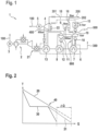
- the power plant 1 is a gas and steam power plant with combined heat and power generation and includes a gas turbine 2 and a steam turbine 4.
- the gas turbine 2 is used to drive a first generator 3, through which electrical energy 100 can be output.
- the steam turbine 4 is used to drive a second generator 5, through which electrical energy 100 can also be output.
- the operation of the gas turbine 2 generates flue gas 300 which is cooled in a heat recovery steam generator 6 in order to to be able to use waste heat from the flue gas 300 .
- an additional firing system 21 can be present between the gas turbine 2 and the heat recovery steam generator 6 in order to additionally heat the flue gas 300 .
- the heat recovery steam generator 6 comprises a preheater 7, an evaporator 8 and a superheater 13, which are provided for heat exchange.
- fresh water 500 is supplied externally or is obtained from condensed steam of the power plant 1 via a deaerator 19 .
- the fresh water 500 is conveyed through the preheater 7 by a feed water pumping device 10 and compressed, as a result of which feed water 600 is provided under a feed water pressure.
- the feed water 600 is transferred to a steam drum 11 . in the in 1 example shown, the feed water pressure is 100 bar.
- the feed water 600 is conveyed from the steam drum 11 through the evaporator 8 via a feed pump 12 . This leads to the evaporator 8 at least partially evaporating the feed water 600 , live steam 400 generated in this way being fed back to the steam drum 11 .
- the live steam 400 is separated from the feed water 600 in the steam drum 11 .
- the live steam 400 is superheated by the superheater 13 and then fed to the steam turbine 4 .
- the steam turbine 4 extracts energy from the live steam 400 and uses this energy to drive the second generator 5 so that residual steam 201 is output at an outlet of the steam turbine 4 .
- the residual steam 201 has a residual steam pressure in the in 1 embodiment shown is 5 bar and is therefore in particular lower than a live steam pressure of, for example, 95 bar.
- a high-pressure bypass 22 can also be present. This means that the steam turbine 4 is bypassed via an alternative bypass path with a throttle and in particular also injection cooling by means of hot water injection (not shown) in order to generate a larger amount of residual steam 201 .
- the fresh water 500 is first preheated in the preheater 7 in order to obtain the feed water 600, then the feed water 600 is evaporated to form live steam 400 in the evaporator 8 and finally the live steam 400 is superheated in the superheater 13.
- the superheater 13 is arranged at the hottest point of a flow of the flue gas 300, the evaporator 8 behind the superheater 13 and the preheater 7 behind the evaporator 8 and thus at a coldest point of the flow of the flue gas 300.
- an additional steam throttle valve 9 is present.
- the additional steam throttle valve 9 is arranged between the steam drum 11 and the preheater 7 and is used to remove feed water 600.
- the feed water 600 is in the additional steam throttle valve 9 to the residual steam pressure, ie in the in 1 shown embodiment to 5 bar, relaxed and fed to an additional steam separation tank 16.
- the additional steam separating tank 16 is used to separate residual water from the additional steam 202, the additional steam 202 being mixed with the residual steam 201 in order to produce the process steam 200, which can be extracted from the power plant 1.
- Such mixing is possible without any problems, since the additional steam 202 has the same pressure as the residual steam 201 due to the additional steam throttle valve 9.
- the residual water that was separated in the additional steam separation tank 16 is fed in particular to the deaerator 19 so that it can be used again as feed water 600.
- the residual steam 201 is condensed in whole or in part in a condenser 15 .
- a bypass 18 is provided for this purpose, through which the outlet of the steam turbine 4 is connected to the condenser 15 .
- the condensed original residual steam 201 is transferred from the condenser 15 to the deaerator 19.
- the additional steam throttle valve 9 is in particular controllable.
- a withdrawal of feed water 600 can thus be regulated, with the result, in particular, that a flow rate through the preheater 7 can also be regulated.
- a flow through the preheater 7 can thus be adjusted in such a way that on the one hand the mass flow through the evaporator 8 is not influenced and at the same time the flue gas 300 is optimally cooled.
- the flue gas 300 is cooled to a low residual temperature above a sulfuric acid dew point, for example to a residual temperature of 90°C.
- the electrical efficiency of the power plant 1 can be compared be increased in a conventional power plant without an additional steam throttle valve 9 in that the process steam 200 is provided completely by the additional steam 202 and thus via the additional steam throttle valve 9 . There is therefore no output of residual steam 201 as process steam.
- the entire residual steam 201 can thus be routed via the bypass 18 into the condenser 15 and thus have a significantly lower pressure than the process steam pressure, as a result of which the power output of the steam turbine 4 is increased.
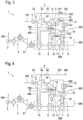
- FIG. 12 schematically shows a QT diagram of the process taking place in the power plant 1 according to the first exemplary embodiment.
- the ordinate shows the temperature value T of the flue gas 300 and the abscissa the amount of heat Q removed from the flue gas 300.
- a maximum energy 20 of the flue gas 300 is shown as a linear curve.
- the profile 30 shows the amount of heat removed according to the process of the power plant 1.
- the advantage of the additional removal of feed water 600 at the additional steam throttle valve 9 is shown as an alternative profile 31 with dashed lines.
- the pinch point 40 is characteristic of QT diagrams. At this point, the curve 30 has the smallest distance to the maximum energy 20, this distance being designed to be approximately 10° C. in particular. It is in 2 also shown that the influence of the removal of the feed water 600, which is represented by the dashed alternative course 31, has effects only on the temperature range below the pinch point 40. The generation of live steam 400, for which the temperature range above the pinch point 40 is mainly relevant, thus remains unaffected by the additional measure. However, it can be seen that compared to the course 30 without additional removal of the feed water 600 at the additional-steam throttle valve 9, a higher quantity of energy ⁇ Q is removed from the flue gas 300 can. A larger proportion of the energy of the flue gas 300 is thus used than in the prior art, as a result of which the efficiency of the power plant 1 is increased compared to the prior art.
- the second exemplary embodiment is essentially identical to the first exemplary embodiment, with the difference in the first exemplary embodiment being that the steam turbine 4 is designed in two stages. It is therefore provided that the first stage 4a, in particular the high-pressure stage, is operated with the live steam 400, as was described in the first exemplary embodiment.
- the residual steam 201 generated in this way can in turn be mixed with the additional steam 202 in order to provide the process steam 200 .
- the second stage 4b of the steam turbine 4, in particular the low-pressure stage, is operated by a drive steam 700.
- the drive steam 700 is produced by expanding the residual water that was separated from the additional steam 202 in the additional steam separating tank 16 .
- Said residual water is expanded by a drive steam throttle valve 14 to the drive steam pressure, which is lower than the residual steam pressure. in the in 3 shown embodiment, this drive steam pressure is 0.5 bar.
- the drive steam 700 is fed to a drive steam separation tank 17, as a result of which residual water can be separated from the drive steam 700 again.
- the residual water from the drive steam separation tank 17 is returned and can run through the preheater 7 again.
- the residual water can be fed to the deaerator 19 . This takes place in particular when the pressure is still greater than 1 bar, otherwise the residual water will preferably be fed into the condenser 15 since the deaerator 19 is advantageously operated at a pressure of approximately 1 bar (absolute).
- bypass 18 does not connect the outlet of the first stage 4a of the steam turbine 4 to the condenser 15, but to the inlet of the second stage 4b of the steam turbine 4. If the residual steam 201 is not required as process steam 200, it can be fed to the second stage 4b of the steam turbine 4.
- the second stage 4b of the steam turbine 4 converts the supplied steam, in particular the working steam 700, into waste steam 800, which is no longer used and is fed directly to the condenser 15.
- a two-stage steam turbine 4 is thus used in the second exemplary embodiment.
- the basic principle of removing feed water 600 remains the same as in the first exemplary embodiment.
- the additional steam 202 has a higher pressure level than is necessary for the operation of the second stage 4b, the working steam 700 can thus be generated easily without the residual steam 201 of the first stage 4a having to be used for this purpose.
- the residual water from the additional steam 202 before the recirculation is used to drive the second stage 4b of the steam turbine 4 as in the first exemplary embodiment.
- FIG. 4 shows another embodiment of the invention.
- the power plant 1 according to a third embodiment, as in 4 shown is almost identical to the power plant 1 according to the second embodiment of the invention.
- the drive steam 700 is not generated from the residual water of the additional steam 202, as in the second embodiment, but directly from the feed water 600.
- the drive steam throttle valve 14 with a feed water line is used for this purpose coupled between the preheater 7 and the steam drum 11. Feedwater 600 is thus removed through the drive steam throttle valve 14 and converted to drive steam 700 by expansion to the drive steam pressure.
- the drive steam separation tank 17 is present, through which the residual water can be separated from the drive steam 700 . Furthermore, the residual water is returned to an input of the preheater 7.
- the generation of additional steam 202 is omitted.
- the process steam 200 is thus formed solely by the residual steam 201 . Since the residual steam 201 does not have to be used to drive the second stage 4b of the steam turbine 4, since this is taken over by the drive steam 700, the amount of process steam 200 is again maximized compared to the prior art.
- the third exemplary embodiment thus also has the same advantages as the previous exemplary embodiments.
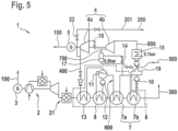
- the fourth exemplary embodiment is almost identical to the third exemplary embodiment, the only difference being the preheater 7 .
- the preheater 7 according to the fourth embodiment has a first preheating area 7a and a second preheating area 7b.
- the first preheating area 7a and the second preheating area 7b are connected in series, with the tapping of the feed water 600 taking place between the first preheating area 7a and the second preheating area 7b, in which the feed water 600 is expanded through the drive steam throttle valve 14 to form the drive steam 700.
- the first preheating area 7a and the second preheating area 7b can be configured identically, so that feed water 600 is branched off exactly in the middle of the preheater 7 .
- the first preheating area 7a can be configured differently from the second preheating area 7b in order to branch off the feed water 600 at any point of the preheater 7 and expand it through the drive steam throttle valve 14 .
- the fourth exemplary embodiment shown can also be combined with the first exemplary embodiment or the second exemplary embodiment.
- the preheater 7 can also be divided into the first preheating area 7a and the second preheating area 7b in the first exemplary embodiment or second exemplary embodiment, with the feed water 600 being removed through the additional steam throttle valve 9 between the first preheating area 7a and the second preheating area 7b.
- the concept according to the invention can also be applied to steam turbines 4 with more than two stages.
- the lower stages can be operated with steam which was obtained by removing and expanding feed water 600 at any point in the preheater 7 or between the preheater 7 and the steam drum 11 .
Landscapes
- Engineering & Computer Science (AREA)
- Chemical & Material Sciences (AREA)
- Combustion & Propulsion (AREA)
- Mechanical Engineering (AREA)
- General Engineering & Computer Science (AREA)
- Physics & Mathematics (AREA)
- Thermal Sciences (AREA)
- Engine Equipment That Uses Special Cycles (AREA)
Description
- Die Erfindung betrifft ein Kraftwerk zur Generierung von elektrischer Energie und Entnahmedampf (Gas- und Dampf-Kraftwerk). Insbesondere ist das erfindungsgemäße Kraftwerk mit einer Gasturbine versehen und arbeitet nach der Kraft-Wärme-Kopplung. Bei dem Kraftwerk ist eine Menge des Entnahmedampfs maximiert. Somit lässt sich Brennstoff in der Gasturbine oder einer Zusatzfeuerung einsparen, da ein benötigter Prozessdampf unter weniger Energieaufwand bereitgestellt wird. Somit können sowohl die Betriebskosten des Kraftwerks als auch dessen CO2-Ausstoß gesenkt werden.
- Aus dem Stand der Technik sind Gas- und Dampfkraftwerke mit Kraft-Wärme-Kopplung bekannt. Beispielsweise geht aus der
US 5,044,163 A ein solches Kraftwerk hervor. Allerdings ist bei diesem Kraftwerk keine Entnahme von Prozessdampf vorgesehen. Aus dem Stand der Technik sind ebenfalls Kraftwerke bekannt, bei denen Prozessdampf entnehmbar ist. Typischerweise werden solche Kraftwerke spezifisch für industrielle Abnehmer von Strom und Wärme gebaut. Die Abgabe von Wärme erfolgt in Form von Prozessdampf. Vorteilhafterweise weisen die Abnehmer einen kontinuierlichen Bedarf an Energie auf. Bei solchen Kraftwerken ist eine Gasturbine vorhanden, deren Rauchgas zum Verdampfen von Speisewasser verwendet wird, wobei der so erzeugte Frischdampf eine Dampfturbine antreibt. Nach Durchlaufen der Dampfturbine ist der Restdampf dem Kraftwerk als Prozessdampf entnehmbar und kann für weitere Prozesse eingesetzt werden. - Andere Kraftwerke sind beispielsweise aus der
DE 199 44 920 B4 oder derDE 28 24 321 A1 bekannt. Außerdem beschreibt dieDE 712 163 A ein weiteres Kraftwerk. - Bei bekannten Kraftwerken kann insbesondere bei geringen Temperaturen des Rauchgases dessen Wärme nicht optimal verwendet werden, so dass die Wärme des Rauchgases verloren geht. Dies führt zu einem verminderten Wirkungsgrad des gesamten Kraftwerks.
- Es ist daher Aufgabe der Erfindung, einen Wirkungsgrad eines Gas- und Dampfkraftwerks zu verbessern.
- Gelöst wird die Aufgabe durch die Merkmale des unabhängigen Anspruchs. Die Unteransprüche haben bevorzugte Weiterbildungen der Erfindung zum Inhalt.
- Die Aufgabe wird somit gelöst durch ein Kraftwerk zur Generierung von elektrischer Energie und Prozessdampf. Das Kraftwerk umfasst eine Gasturbine, eine Dampfturbine und einen AbhitzeDampferzeuger. Der Abhitze-Dampferzeuger ist mindestens einstufig ausgebildet und kann insbesondere aber auch mehrstufig ausgebildet sein. Die Gasturbine dient zum Antreiben eines ersten Generators zum Generieren von elektrischer Energie durch Verbrennung eines Brennstoffs zu Rauchgas. Die Dampfturbine dient zum Antreiben eines zweiten Generators. Die Dampfturbine weist zumindest eine erste Stufe, insbesondere eine Hochdruckstufe, auf, um einen Frischdampf zu einem Restdampf zu wandeln. Auf diese Weise wird dem Frischdampf Energie entzogen, um den Generator anzutreiben. Der Restdampf stellt zumindest einen Teil des Prozessdampfs dar, der dem Kraftwerk entnommen werden kann. Somit wird insbesondere der gesamte Restdampf oder zumindest ein Teil des Restdampfes als Prozessdampf dem Kraftwerk entnommen. Der Abhitzedampferzeuger dient zum Erzeugen des Frischdampfs aus Frischwasser mittels einer Abwärme des Rauchgases. Das Frischwasser ist dem Kraftwerk entweder zuführbar, insbesondere um entnommenen Prozessdampf auszugleichen, und/oder kann aus einem Teil des Restdampfs gewonnen werden, indem dieser kondensiert wird. Der Abhitzedampferzeuger umfasst insbesondere mehrere Wärmetauscher, um das Frischwasser zu dem Frischdampf zu wandeln. Es ist vorgesehen, dass der Restdampf einen Restdampfdruck aufweist, der geringer als ein Frischdampfdruck des Frischdampfs ist. Somit weist der Frischdampf eine höhere Energie auf als der Restdampf, die in der Dampfturbine zum Antreiben des zweiten Generators verwendet werden kann. Die Dampfturbine kann lediglich die erste Stufe, insbesondere die Hochdruckstufe, aufweisen. In diesem Fall ist die Dampfturbine einstufig ausgebildet. Alternativ kann die Dampfturbine auch eine zusätzliche zweite Stufe, insbesondere eine Niederdruckstufe, aufweisen. In diesem Fall ist die Dampfturbine zweistufig ausgebildet.
- Es ist vorgesehen, dass der Abhitzedampferzeuger einen Vorwärmer und einen Verdampfer aufweist. Der Vorwärmer dient zum Vorwärmen des Frischwassers zu Speisewasser. Der Verdampfer dient zum Verdampfen des Speisewassers zu dem Frischdampf. Dabei ist insbesondere vorgesehen, dass der Vorwärmer und der Verdampfer jeweils einen Wärmetauscher umfassen, die in einen Strom des Rauchgases eingebracht sind. Der Verdampfer ist dabei an einer heißeren Stelle des Stroms des Rauchgases angeordnet als der Vorwärmer. Das Speisewasser weist insbesondere einen Speisewasserdruck auf, der höher als der Restdampfdruck ist. Der Speisewasserdruck wird insbesondere durch eine Pumpeneinheit gebaut, durch die Frischwasser durch den Vorwärmer pumpbar ist. Besonders vorteilhaft handelt es sich bei dem Speisewasserdruck um einen Druck zwischen 50 bar und 150 bar, bevorzugt zwischen 80 bar und 120 bar, besonders um 100 bar. Bei dem Restdampfdruck handelt es sich insbesondere um einen Druck zwischen 1 bar und 10 bar, insbesondere zwischen 3 bar und 7 bar, besonders bevorzugt um 5 bar. Bei dem Frischdampfdruck handelt es sich bei Volllast insbesondere um den Speisewasserdruck abzüglich 2 bar bis 5 bar Druckverlust, bei einem Teillastbetrieb insbesondere um einen Druck zwischen 10 bar und 20 bar, insbesondere zwischen 13 bar und 17 bar, besonders bevorzugt um 15 bar.
- Das Kraftwerk weist ferner ein Drosselventil oder mehrere, stufenweise Drosselventile sowie bevorzugt zumindest einen Wasserabscheider auf. Das zumindest eine Drosselventil ist zum Entspannen eines Teils des Speisewassers ausgebildet. Dabei kann das Drosselventil entweder ausgebildet sein, den Teil des Speisewassers auf den Restdampfdruck zu entspannen, oder alternativ auf einen Antriebsdampfdruck. Im Falle des Entspannens auf den Restdampfdruck wird ein Zusatzdampf generiert, der denselben Dampfdruck aufweist wie der Prozessdampf. Somit kann der Zusatzdampf ebenso wie der Prozessdampf dem Kraftwerk entnommen werden, um eine Dampfentnahme zu erhöhen. Im Falle des Entspannens auf den Antriebsdampfdruck wird ein Antriebsdampf generiert. Der Antriebsdampf dient insbesondere zum Betreiben einer zweiten Stufe der Dampfturbine. Der Antriebsdampfdruck ist geringer als der Restdampfdruck. Insbesondere handelt es sich bei dem Antriebsdampfdruck um einen Druck zwischen 0,1 bar und 3 bar, insbesondere zwischen 0,3 bar und 0,7 bar, besonders bevorzugt um 0,5 bar. Befindet sich das Kraftwerk in einem Teillastbetrieb, so ist der Antriebsdampfdruck insbesondere geringer als bei Volllastbetrieb. Der Antriebsdampfdruck ist bei Teillastbetrieb bevorzugt erheblich geringer als bei Volllastbetrieb. Die zweite Stufe der Dampfturbine ist insbesondere eine Niederdruckstufe, weswegen der geringere Antriebsdampfdruck ausreicht, um die Dampfturbine anzutreiben, insbesondere bei Mindestmassenstrom. Es muss somit kein Restdampf, der aus der ersten Stufe ausgegeben wird, zum Antreiben der zweiten Stufe verwendet werden. Vielmehr ist ermöglicht, dass der gesamte Restdampf als Prozessdampf ausgegeben werden kann.
- Durch das erfindungsgemäße Kraftwerk ist, insbesondere im Teillastbetrieb ein Wirkungsgrad erheblich vergrößert. Dies geschieht dadurch, dass eine Dampfauskopplung aus dem Kraftwerk erhöht ist, indem die Menge an Prozessdampf vergrößert wird. Dies wird dadurch erreicht, dass entweder zusätzlich zu dem Restdampf auch der Zusatzdampf als Prozessdampf entnommen wird oder dadurch, dass eine zweite Stufe der Dampfturbine nicht oder nur vermindert mit dem Restdampf aus der ersten Stufe betrieben werden muss, wodurch ein größerer Anteil des Restdampfs als Prozessdampf entnommen werden kann. Da das Kraftwerk vorsieht, dass Speisewasser vor dem Verdampfen entnommen wird, kann ein höherer Durchfluss durch den Vorwärmer realisiert werden, ohne dass die Dampferzeugung nennenswert beeinflusst wird. Durch den höheren Durchfluss von Frischwasser durch den Vorwärmer erfolgt eine verbesserte Abkühlung des Rauchgases, so dass die Wärmeenergie des Rauchgases auch bei geringeren Temperaturen optimal verwendet werden kann. Dies führt zu einem erhöhten Wirkungsgrad des Kraftwerks. Insbesondere ist eine Regelvorrichtung vorhanden, bei der der Massestrom des Frischwassers und der Durchfluss des Speisewassers durch das Drosselventil derart geregelt wird, dass der Durchfluss durch den Verdampfer von der Maßnahme unbeeinflusst bleibt und gleichzeitig eine optimale Auskühlung des Rauchgases erfolgt. Eine optimale Auskühlung des Rauchgases liegt insbesondere dann vor, wenn das Rauchgas bis auf 100°C, bevorzugt bis auf 90°C, abgekühlt wird. Besonders vorteilhaft erfolgt die Auskühlung bis an einen Schwefelsäuretaupunkt oder bis an einen vordefinierten Toleranzbereich um den Schwefelsäuretaupunkt, wobei der Schwefelsäuretaupunkt insbesondere nicht unterschritten wird, um Korrosion zu vermeiden.
- In einer bevorzugten Ausführungsform ist vorgesehen, dass das Drosselventil ein Zusatzdampf-Drosselventil ist. Das Zusatzdampf-Drosselventil dient zum Entspannen des Teils des Speisewassers auf den Restdampfdruck zur Generierung des Zusatzdampfs. Somit ist vorgesehen, dass nach dem Entspannen des Teils des Speisewassers auf den Restdampfdruck der Zusatzdampf aus dem Kraftwerk entnommen wird. Der Zusatzdampf wird dazu mit dem Restdampfdruck zu dem Prozessdampf gemischt. Das Kraftwerk ist somit ausgelegt, dass der Zusatzdampf mit dem Restdampf zu dem Prozessdampf mischbar ist. Somit wird die Menge des Prozessdampfs, die aus dem Kraftwerk entnommen werden kann, erhöht. Da die vergrößerte Menge des Prozessdampfes daraus resultiert, dass ein höherer Massenstrom durch den Vorwärmer fließt, ist außerdem ermöglicht, das Rauchgas auf eine niedrige Temperatur abzukühlen. Insbesondere wird das Rauchgas auf eine niedrigere Temperatur als im Stand der Technik abgekühlt, wodurch eine größere Menge Wärmeenergie aus dem Rauchgas entzogen wird. Damit kann die vorhandene Energie des Rauchgases besser als im Stand der Technik genutzt werden.
- In einer weiteren bevorzugten Ausführungsform ist vorgesehen, dass die Dampfturbine zweistufig ausgebildet ist. Somit weist die Dampfturbine neben der zuvor beschriebenen ersten Stufe eine zweite Stufe auf. Die zweite Stufe ist insbesondere eine Niederdruckstufe und dient zum Wandeln eines Antriebsdampfes zu einem Verlustdampf. Der Verlustdampf ist lediglich zum Kondensieren vorgesehen und wird insbesondere nicht weiter verwendet. Der Antriebsdampf ist vorteilhafterweise durch Entspannen von Restwasser aus dem Zusatzdampf an einem Antriebsdampf-Drosselventil erzeugbar. Insbesondere entspricht der so erzeugte Antriebsdampf dem zuvor beschriebenen Antriebsdampf, wobei in diesem Ausführungsbeispiel der Antriebsdampf nicht aus dem Speisewasser direkt, sondern aus dem Restwasser des Zusatzdampfes erzeugt wird. Dazu wird das Restwasser von dem Zusatzdampf abgeschieden und durch das Antriebsdampf-Drosselventil erneut entspannt. Da der Antriebsdampfdruck geringer als der Restdampfdruck ist, ist ein solches Entspannen möglich, um die zweite Stufe, insbesondere die Niederdruckstufe, der Dampfturbine zu betreiben. Die zweite Stufe, insbesondere die Niederdruckstufe, weist typischerweise einen Mindestmassenstrom auf, der zur Vermeidung der Ventilation nicht unterschritten werden darf. Beispielsweise darf die Grenze von 10% des Massenstroms nicht unterschritten werden. Dieser Mindestmassenstrom wird im Stand der Technik üblicherweise aus dem Restdampf abgezweigt und kann somit nicht für den Prozessdampf verwendet werden. Wird die zweite Stufe mit dem Mindestmassenstrom betrieben, so liegt allerdings an deren Eingang aufgrund des Stodola-Gesetzes bereits ein niedriger Druck vor, da ein niedriges Druckgefälle über die zweite Stufe der Turbine vorherrscht. Wie bereits beschrieben, ist der Antriebsdampfdruck geringer als der Restdampfdruck, so dass im Stand der Technik der Restdampf stark gedrosselt werden muss, um den Antriebsdampfdruck zu erreichen. Daher ist der Mindestmassestrom optimal aus dem Zusatzdampf zu gewinnen, so dass der Restdampf nicht zum Antreiben der zweiten Stufe verwendet werden muss. Dies führt insbesondere im Teillastbetrieb zu einer erheblichen Steigerung des Wirkungsgrads des Kraftwerks. Unterstützt wird dies insbesondere dadurch, dass der Vorwärmer für den Volllastbetrieb auszulegen ist, wodurch der Vorwärmer im Teillastbetrieb überdimensioniert ist. Dies wird durch den höheren Frischwasserstrom durch den Vorwärmer zur Generierung des Zusatzdampfes und/oder Antriebsdampfes ausgenutzt.
- In einer alternativen Ausführungsform zu den zuvor beschriebenen Ausführungsformen ist vorgesehen, dass die Dampfturbine wiederum zweistufig ausgebildet ist, wobei die zweite Stufe, insbesondere eine Niederdruckstufe, zum Wandeln des Antriebsdampfes zu einem Verlustdampf ausgebildet ist. Wiederum ist der Verlustdampf zum Kondensieren vorgesehen und wird insbesondere nicht weiter verwendet. Der Antriebsdampf wird vorteilhafterweise durch das Drosselventil, das ein Antriebsdampf-Drossel-Ventil ist, generiert. Dies geschieht dadurch, dass der Teil des Speisewassers auf den Antriebsdampfdruck entspannt wird, wodurch durch das Antriebsdampf-Drosselventil der Antriebsdampf generiert wird. In diesem Fall erfolgt kein Generieren von Zusatzdampf, so dass der Restdampf den gesamten Prozessdampf darstellt. Da allerdings kein Restdampf zum Antreiben der zweiten Stufe verwendet werden muss, sondern die zweite Stufe vielmehr durch den Antriebsdampf angetrieben wird, kann der gesamte Restdampf den Prozessdampf darstellen. Insbesondere treten dieselben Vorteile wie in den vorherigen Ausführungsbeispielen auf. Somit wird wiederum erreicht, dass durch eine Vergrößerung des Massenstroms durch den Vorwärmer die Menge an Speisewasser erhöht wird, wobei ein Teil des Speisewassers zu Antriebsdampf gewandelt wird, um die zweite Stufe der Dampfturbine zu betreiben. Dies führt wiederum zu einer Steigerung des Wirkungsgrads des Kraftwerks, da das Rauchgas auf niedrigere Temperaturen abgekühlt werden kann, um somit eine vorhandene Wärmemenge des Rauchgases optimal zu nutzen. Ein Vorteil dieser Ausführungsform ist insbesondere die vereinfachte Schaltung.
- In einem Betriebspunkt, in dem nur wenig Prozessdampf benötigt wird, kann der elektrische Wirkungsgrad des Kraftwerks, insbesondere mit einer einstufigen Dampfturbine, gegenüber einem herkömmlichen Kraftwerk ohne Zusatzdampfdrosselventil gesteigert werden, indem vorteilhafterweise der Prozessdampf komplett durch den Zusatzdampf und somit über das Zusatzdampfdrosselventil bereitgestellt wird. Es erfolgt somit keine Ausgabe von Restdampf als Prozessdampf. Der gesamte Restdampf kann somit über einen Bypass abgeführt, insbesondere in den Kondensator geleitet werden. Dadurch kann der Restdampf einen wesentlich niedrigeren Druck als einen geforderten Prozessdampfdruck aufweisen, wodurch die Leistungsabgabe der Dampfturbine gesteigert wird.
- Das Kraftwerk weist vorteilhafterweise eine Speisewasserpumpvorrichtung auf. Die Speisewasserpumpvorrichtung dient zum Fördern von Frischwasser durch den Vorwärmer und zum Generieren des Speisewasserdrucks. Die Speisewasserpumpvorrichtung umfasst zumindest eine Pumpe, vorteilhafterweise zwei oder mehrere Pumpen. In dem Kraftwerk ist üblicherweise lediglich eine einzige Pumpe der Speisewasserpumpvorrichtung aktiv, während die übrigen Pumpen als Ersatz vorgehalten werden. Während einer Entnahme von Speisewasser durch Entspannen des Speisewassers an dem Drosselventil ist ein höherer Massenstrom durch die Speisewasserpumpvorrichtung vonnöten als ohne eine solche Entnahme. Daher kann vorteilhafterweise während der Entnahme und des Entspannens des Speisewassers an dem Drosselventil die als Ersatz vorgehaltene zweite oder weitere Pumpe zur Erhöhung des Massenstroms durch den Vorwärmer verwendet werden.
- Vorteilhafterweise ist vorgesehen, dass der Abhitzedampferzeuger eine Dampftrommel aufweist. Die Dampftrommel dient zum Trennen von Frischdampf und Speisewasser. Aus der Dampftrommel ist der Frischdampf der Dampfturbine zuführbar, wobei der Frischdampf vor dem Zuführen durch die Dampfturbine in einem Erhitzer vorteilhafterweise überhitzt wird. Der Überhitzer ist insbesondere an einer heißesten Stelle des Stroms des Rauchgases angebracht. Weiterhin ist der Dampftrommel das Speisewasser aus dem Vorwärmer zuführbar. So dient insbesondere die Dampftrommel zum Abscheiden des Speisewasser aus dem Frischdampf. Insbesondere kann das Speisewasser an einer beliebigen Stelle zwischen der Dampftrommel und dem Vorwärmer, besonders bevorzugt auch an einer beliebigen Stelle des Vorwärmers, entnommen und durch das Drosselventil entspannt werden.
- Besonders vorteilhaft ist vorgesehen, dass der Abhitzedampferzeuger eine Förderpumpe zum Fördern von Speisewasser aus der Dampftrommel durch den Verdampfer zurück in die Dampftrommel aufweist. Somit ist aus dem Speisewasser Frischdampf generierbar. In der Dampftrommel wird der generierte Frischdampf von restlichem Speisewasser getrennt, so dass ausschließlich Frischdampf ohne das Speisewasser der Dampfturbine zuführbar ist.
- Das Kraftwerk weist weiterhin vorteilhafterweise einen Zusatzdampf-Abscheidebehälter auf. Alternativ oder zusätzlich weist das Kraftwerk vorteilhafterweise einen Antriebsdampf-Abscheidebehälter auf. Der Zusatzdampf-Abscheidebehälter dient zum Abscheiden von Restwasser aus dem Zusatzdampf. Der Antriebsdampf-Abscheidebehälter dient zum Abscheiden von Restwasser aus dem Antriebsdampf. Somit lassen sich durch die jeweiligen Abscheidebehälter der Zusatzdampf bzw. der Antriebsdampf von dem Restwasser, das an dem entsprechenden Drosselventil nicht verdampft ist, trennen. Das Restwasser, das aus dem Zusatzdampf abgeschieden wurde, lässt sich insbesondere erneut entspannen, um den Antriebsdampf zu erzeugen. Das Restwasser, das aus dem Antriebsdampf abgeschieden wurde, wird insbesondere kondensiert oder abgekühlt und als Frischwasser dem Vorwärmer erneut zugeführt. Insgesamt kann das jeweilige Restwasser je nach Druckniveau in einem Kondensator, sowie vor, in oder nach dem Entgaser in das Speisewasser zurückgegeben werden. In letzterem Fall muss der Druck insbesondere größer als 1 bar sein, wodurch der Entgaser beheizt werden kann. Das noch heiße Restwasser kann in diesem Fall den Wärmebedarf des Entgasers zumindest teilweise decken. Durch eine variable Aufteilung des Restwassers auf eine Zuführung in den Kondensator und nach dem Kondensator kann die Eintrittstemperatur in den Vorwärmer geregelt werden, so dass insbesondere der Schwefelsäuretaupunkt am Austritt des Abhitzedampferzeugers nicht unterschritten wird. Nicht verdampftes Restwasser kann insbesondere in einem Wärmetauscher zur Brenngasvorwärmung genutzt werden. Ebenso kann bevorzugt das nicht verdampfte Restwasser nach Druckerhöhung in einer Pumpe durch Einspritzung in das Brenngas zur effizienten Vorwärmung mit Dampfsättigung im Brenngas genutzt werden, was zu einer Emissionsreduktion und zu einer Leistungssteigerung führt. Somit kann die Energie des Restwassers optimal verwendet werden, um den Wirkungsgrad des Kraftwerks weiter zu erhöhen.
- Das Kraftwerk weist außerdem vorteilhafterweise einen Bypass auf. Über den Bypass ist der Restdampf von einem Ausgang der Dampfturbine zu einem Kondensator oder von einem Ausgang der ersten Stufe zu einem Eingang der zweiten Stufe überführbar. Somit kann insbesondere solcher Restdampf, der nicht als Prozessdampf entnommen wird, abgeführt werden.
- Das Drosselventil ist vorteilhafterweise an einem Ausgang des Vorwärmers angebracht. Somit wird das Speisewasser bevorzugt an einem Ausgang des Vorwärmers, d.h., an einer heißesten Stelle des Vorwärmers, entnommen. Alternativ kann das Drosselventil an einem beliebigen anderen Punkt des Vorwärmers angebracht sein. Insbesondere ist vorgesehen, dass der Vorwärmer einen ersten Vorwärmbereich und einen zweiten Vorwärmbereich aufweist, die hintereinander geschaltet sind und zwischen denen das Drosselventil angebracht ist. In diesem Fall wird das Speisewasser aus der Mitte des Vorwärmers entnommen.
- Durch das erfindungsgemäße Kraftwerk ist ermöglicht, die Wahl des Frischdampfdrucks unabhängig von dem Massestrom von dem Vorwärmer auszugestalten. Insbesondere ist für das Ausbilden der Eigenschaften des Frischdampfes eine Temperatur oberhalb des Pinch-Points (auch Zwickpunkt genannt) maßgeblich, während die Erhöhung des Massenstroms durch den Vorwärmer lediglich Auswirkungen auf den Bereich unterhalb des Pinch-Points umfasst. Insbesondere kann auch eine Auskühlung des Rauchgases, vorteilhafterweise bei aktiver Zusatzfeuerung, durch Anpassung des Massenstroms durch den Vorwärmer, optimiert werden.
- Der zusätzliche Massestrom durch den Vorwärmer kann in einer bevorzugten Ausführungsform zwischen 0% und 200% des ursprünglich für die Herstellung des Frischdampfs vorgesehenen Massenstroms betragen. In einer besonders vorteilhaften Ausführungsform beträgt dieser Massestrom zwischen 20% und 50% des für die Herstellung des Frischdampfes ursprünglich vorgesehenen Massestroms. Insbesondere wird der Durchfluss durch den Vorwärmer für jeden Betriebspunkt derart angepasst, dass eine optimale Auskühlung des Rauchgases erfolgt, während gleichzeitig der Massestrom durch den Verdampfer von dem Strom durch den Vorwärmer nicht beeinflusst wird.
- Vorteilhafterweise weist das Kraftwerk eine Hochdruckumleitung auf. Das bedeutet, dass die Dampfturbine, insbesondere eine Hochdruckturbine, über einen zusätzlichen, alternativen Umgehungs-Pfad mit eigenem Drosselventil und Einspritzkühlung umgangen wird, wodurch die Menge des Restdampfes vergrößert wird, um somit die Menge an Prozessdampf zu vergrößern. Die Hochdruckumleitung umfasst insbesondere eine Drossel und/oder eine Heißwassereinspritzung, um den Frischdampf, der über die Hochdruckumleitung an der Dampfturbine vorbei geleitet wird, auf den Restdampfdruck zu entspannen und mit dem Restdampf zu mischen. Alternativ oder zusätzlich kann eine Zusatzfeuerung vorgesehen sein. Die Zusatzfeuerung ermöglicht ein zusätzliches Erwärmen des Rauchgases nach Austritt aus der Gasturbine. Somit steht eine größere Wärmemenge für den Abhitzedampferzeuger zur Verfügung. Durch alles diese Maßnahmen lässt sich die erzeugte Menge an Prozessdampf maximieren.
- Bevorzugt ist vorgesehen, dass das Drosselventil zur Generierung des Zusatzdampfs und/oder Antriebsdampfs eingerichtet ist, eine solche Menge an Speisewasser zu entspannen, um eine vordefinierte Auskühlung des Rauchgases in allen Lastpunkten zu erreichen. Dadurch wird die Menge an Speisewasser, das durch das Drosselventil entnommen wird, danach geregelt, welche Auskühlung des Rauchgases erreicht werden soll. Somit findet stets eine optimale Auskühlung des Rauchgases statt.
- Ebenso ist vorteilhaft, dass das Drosselventil eingerichtet ist, das Speisewasser nur im Teillastbetrieb des Kraftwerks zu entspannen. Somit findet die Entnahme von Speisewasser an dem Drosselventil nur dann statt, wenn das Kraftwerk im Teillastbetrieb arbeitet. Gerade im Teillastbetrieb hat das Generieren von Antriebsdampf oder Zusatzdampf eine hohe Auswirkung auf den Wirkungsgrad des Kraftwerks.
- Weitere Einzelheiten, Vorteile und Merkmale der vorliegenden Erfindung ergeben sich aus nachfolgender Beschreibung von Ausführungsbeispielen anhand der Zeichnung. Es zeigt:
- Fig. 1
- eine schematische Abbildung eines Kraftwerks gemäß einem ersten Ausführungsbeispiel der Erfindung,
- Fig. 2
- eine schematische Ansicht eines Q-T-Diagramms des Kraftwerks gemäß dem ersten Ausführungsbeispiel der Erfindung,
- Fig. 3
- eine schematische Ansicht eines Kraftwerks gemäß einem zweiten Ausführungsbeispiel der Erfindung,
- Fig. 4
- eine schematische Ansicht eines Kraftwerks gemäß einem dritten Ausführungsbeispiel der Erfindung, und
- Fig. 5
- eine schematische Ansicht eines Kraftwerks gemäß einem vierten Ausführungsbeispiel der Erfindung.
-
Fig. 1 zeigt schematisch ein Kraftwerk 1 gemäß einem ersten Ausführungsbeispiel der Erfindung. Das Kraftwerk 1 ist ein Gas- und Dampfkraftwerk mit Kraft-Wärme-Kopplung und umfasst eine Gasturbine 2 sowie eine Dampfturbine 4. Die Gasturbine 2 dient zum Antreiben eines ersten Generators 3, durch den elektrische Energie 100 ausgebbar ist. Die Dampfturbine 4 dient zum Antreiben eines zweiten Generators 5, durch den ebenfalls elektrische Energie 100 ausgebbar ist. - Durch den Betrieb der Gasturbine 2 wird Rauchgas 300 generiert, das in einem Abhitzedampferzeuger 6 abgekühlt wird, um eine Abwärme des Rauchgases 300 verwenden zu können. Zwischen der Gasturbine 2 und dem Abhitzedampferzeuger 6 kann insbesondere eine Zusatzfeuerung 21 vorhanden sei, um das Rauchgas 300 zusätzlich zu erwärmen. Der Abhitzedampferzeuger 6 umfasst einen Vorwärmer 7, einen Verdampfer 8 und einen Überhitzer 13, die zum Wärmetauschen vorgesehen sind. Es wird dazu Frischwasser 500 von extern zugeführt oder über einen Entgaser 19 aus kondensiertem Dampf des Kraftwerks 1 gewonnen. Das Frischwasser 500 wird durch eine Speisewasserpumpvorrichtung 10 durch den Vorwärmer 7 gefördert und gespannt, wodurch Speisewasser 600 unter einem Speisewasserdruck bereitgestellt wird. Das Speisewasser 600 wird in eine Dampftrommel 11 überführt. In dem in
Fig. 1 gezeigten Beispiel beträgt der Speisewasserdruck 100 bar. Von der Dampftrommel 11 wird das Speisewasser 600 über eine Förderpumpe 12 durch den Verdampfer 8 gefördert. Dies führt dazu, dass der Verdampfer 8 das Speisewasser 600 zumindest teilweise verdampft, wobei ein so generierter Frischdampf 400 erneut der Dampftrommel 11 zugeführt wird. In der Dampftrommel 11 erfolgt ein Abscheiden des Frischdampfes 400 von dem Speisewasser 600. Der Frischdampf 400 wird durch den Überhitzer 13 überhitzt und anschließend der Dampfturbine 4 zugeführt. Die Dampfturbine 4 entzieht dem Frischdampf 400 Energie und treibt mit dieser Energie den zweiten Generator 5 an, so dass an einem Ausgang der Dampfturbine 4 ein Restdampf 201 ausgegeben wird. Der Restdampf 201 weist einen Restdampfdruck auf, der in dem inFig. 1 gezeigten Ausführungsbeispiel 5 bar beträgt und damit insbesondere geringer als ein Frischdampfdruck von beispielsweise 95 bar ist. Es kann insbesondere auch eine Hochdruckumleitung 22 vorhanden sein. Das bedeutet, dass die Dampfturbine 4 über einen alternativen Umgehungs-Pfad mit Drossel und insbesondere auch Einspritzkühlung durch Heißwassereinspritzung (nicht gezeigt) umgangen wird, um eine größere Menge an Restdampf 201 zu generieren. - Um die Dampfturbine 4 anzutreiben, erfolgt somit zunächst ein Vorwärmen des Frischwassers 500 im Vorwärmer 7, um das Speisewasser 600 zu erhalten, anschließend ein Verdampfen des Speisewassers 600 zu Frischdampf 400 im Verdampfer 8 und zuletzt ein Überhitzen des Frischdampfs 400 im Überhitzer 13. Daher ist insbesondere vorgesehen, dass der Überhitzer 13 an der heißesten Stelle eines Stroms des Rauchgases 300 angeordnet ist, der Verdampfer 8 hinter dem Überhitzer 13 und der Vorwärmer 7 hinter dem Verdampfer 8 und damit an einer kältesten Stelle des Stroms des Rauchgases 300.
- Des Weiteren ist vorgesehen, dass ein Zusatzdampfdrosselventil 9 vorhanden ist. Das Zusatzdampf-Drosselventil 9 ist zwischen der Dampftrommel 11 und dem Vorwärmer 7 angeordnet und dient zum Entnehmen von Speisewasser 600. Das Speisewasser 600 wird in dem Zusatzdampf-Drosselventil 9 auf den Restdampfdruck, d.h., in dem in
Fig. 1 gezeigten Ausführungsbeispiel auf 5 bar, entspannt und einen Zusatzdampf-Abscheidebehälter 16 zugeführt. Der Zusatzdampf-Abscheidebehälter 16 dient zum Abscheiden von Restwasser aus dem Zusatzdampf 202, wobei der Zusatzdampf 202 mit dem Restdampf 201 gemischt wird, um so den Prozessdampf 200, der dem Kraftwerk 1 entnehmbar ist, zu erzeugen. Ein solches Mischen ist problemlos möglich, da durch das Zusatzdampf-Drosselventil 9 der Zusatzdampf 202 denselben Druck aufweist wie der Restdampf 201. Das Restwasser, das in dem Zusatzdampf-Abscheidebehälter 16 abgeschieden wurde, wird insbesondere dem Entgaser 19 zugeführt, um somit erneut als Speisewasser 600 verwendet werden zu können. - Durch das Abzweigen von Speisewasser 600 an dem ZusatzdampfDrosselventil 9 ist naturgemäß eine größere Menge an Speisewasser 600 notwendig, als ohne eine solche Abzweigung. Dies bedeutet, dass der Massestrom durch den Vorwärmer 7 mit Abzweigung von Speisewasser 600 größer ist als ohne Abzweigung von Speisewasser 600. Somit erfolgt ein stärkeres Auskühlen des Rauchgases 300, wodurch die Wärmeenergie des Rauchgases 300, insbesondere bei niedrigen Temperaturen, optimal verwendet werden kann. Insbesondere wird die Energie des Rauchgases 300 dazu verwendet, zusätzlich zu dem Restdampf 201 Zusatzdampf 202 zu produzieren, so dass die gesamte Menge an ausgebbarem Prozessdampf 200 vergrößert ist. Dadurch ist ein Wirkungsgrad des Kraftwerks 1 verbessert. Insbesondere ist im Teillastbetrieb der Vorwärmer 7 überdimensioniert, da dieser für den Volllastbetrieb auszulegen ist. Somit kann die Kapazität des Vorwärmers 7 dadurch ausgeschöpft werden, dass zusätzliches Speisewasser 600 generiert wird, das durch das Zusatzdampf-Drosselventil 9 zu Zusatzdampf 202 entspannt wird.
- Falls nicht der gesamte erzeugte Prozessdampf 200 benötigt oder entnommen wird, wird der Restdampf 201 ganz oder teilweise in einem Kondensator 15 kondensiert. Dazu ist ein Bypass 18 vorgesehen, durch den der Ausgang der Dampfturbine 4 mit dem Kondensator 15 verbunden ist. Von dem Kondensator 15 erfolgt eine Übergabe des kondensierten ursprünglichen Restdampfs 201 an den Entgaser 19.
- Das Zusatzdampf-Drosselventil 9 ist insbesondere steuerbar. So kann eine Entnahme von Speisewasser 600 geregelt werden, was insbesondere zur Folge hat, dass auch eine Durchflussmenge durch den Vorwärmer 7 geregelt werden kann. So lässt sich ein Durchfluss durch den Vorwärmer 7 derart einstellen, dass einerseits der Massenstrom durch den Verdampfer 8 nicht beeinflusst wird, gleichzeitig auch das Rauchgas 300 optimal ausgekühlt wird. Insbesondere wird das Rauchgas 300 auf eine niedrige Resttemperatur oberhalb eines Schwefelsäuretaupunkts, beispielsweise auf eine Resttemperatur von 90°C abgekühlt.
- In einem Betriebspunkt, in dem nur wenig Prozessdampf benötigt wird, kann der elektrische Wirkungsgrad des Kraftwerks 1 gegenüber einem herkömmlichen Kraftwerk ohne Zusatzdampfdrosselventil 9 gesteigert werden, indem der Prozessdampf 200 komplett durch den Zusatzdampf 202 und somit über das Zusatzdampfdrosselventil 9 bereitgestellt wird. Es erfolgt somit keine Ausgabe von Restdampf 201 als Prozessdampf. Der gesamte Restdampf 201 kann somit über den Bypass 18 in den Kondensator 15 geleitet werden und dadurch einen wesentlich niedrigeren Druck als den Prozessdampfdruck aufweisen, wodurch die Leistungsabgabe der Dampfturbine 4 gesteigert wird.
-
Fig. 2 zeigt schematisch ein Q-T-Diagramm des in dem Kraftwerk 1 gemäß dem ersten Ausführungsbeispiel ablaufenden Prozesses. Dabei zeigt die Ordinate den Temperaturwert T des Rauchgases 300 und die Abszisse die aus dem Rauchgas 300 entnommene Wärmemenge Q. Es ist eine maximale Energie 20 des Rauchgases 300 als linearer Verlauf dargestellt. Der Verlauf 30 zeigt die entnommene Wärmemenge gemäß dem Prozess des Kraftwerks 1. Dabei ist der Vorteil durch die zusätzliche Entnahme von Speisewasser 600 an dem Zusatzdampf-Drosselventil 9 als gestrichelter Alternativverlauf 31 eingezeichnet. - Charakteristisch für Q-T-Diagramme ist der Pinch-Point 40. An diesem Punkt weist der Verlauf 30 den geringsten Abstand zu der maximalen Energie 20 auf, wobei dieser Abstand insbesondere auf etwa 10°C ausgelegt ist. Es ist in
Fig. 2 weiterhin gezeigt, dass der Einfluss der Entnahme des Speisewassers 600, der durch den gestrichelten Alternativverlauf 31 dargestellt ist, Auswirkungen lediglich auf dem Temperaturbereich unterhalb des Pinch-Points 40 hat. Somit bleibt die Generierung von Frischdampf 400, für die hauptsächlich der Temperaturbereich oberhalb des Pinch-Points 40 relevant ist, durch die zusätzliche Maßnahme unberührt. Allerdings ist ersichtlich, dass im Vergleich zu dem Verlauf 30 ohne zusätzliche Entnahme des Speisewassers 600 an dem Zusatzdampf-Drosselventil 9 eine höhere Energiemenge ΔQ aus dem Rauchgas 300 entnommen werden kann. Somit wird ein größerer Anteil der Energie des Rauchgases 300 als im Stand der Technik genutzt, wodurch ein Wirkungsgrad des Kraftwerks 1 gegenüber dem Stand der Technik erhöht ist. -
Fig. 3 zeigt ein zweites Ausführungsbeispiel der Erfindung. Das zweite Ausführungsbeispiel ist im Wesentlichen identisch zu dem ersten Ausführungsbeispiel, wobei im Unterschied zu dem ersten Ausführungsbeispiel die Dampfturbine 4 zweistufig ausgebildet ist. Daher ist vorgesehen, dass die erste Stufe 4a, insbesondere die Hochdruckstufe, mit dem Frischdampf 400 betrieben wird, wie dies im ersten Ausführungsbeispiel beschrieben wurde. Der so generierte Restdampf 201 ist wiederum mit dem Zusatzdampf 202 mischbar, um den Prozessdampf 200 bereitzustellen. - Die zweite Stufe 4b der Dampfturbine 4, insbesondere die Niederdruckstufe, wird durch einen Antriebsdampf 700 betrieben. Der Antriebsdampf 700 entsteht durch Entspannen des Restwassers, das in dem Zusatzdampf-Abscheidebehälter 16 aus dem Zusatzdampf 202 abgeschieden wurde. Besagtes Restwasser wird durch ein Antriebsdampf-Drosselventil 14 auf den Antriebsdampfdruck entspannt, der geringer ist als der Restdampfdruck. In dem in
Fig. 3 gezeigten Ausführungsbeispiel beträgt dieser Antriebsdampfdruck 0,5 bar. Wiederum erfolgt ein Zuführen des Antriebsdampfs 700 zu einem Antriebsdampf-Abscheidebehälter 17, wodurch erneut Restwasser aus dem Antriebsdampf 700 abscheidbar ist. Das Restwasser aus dem Antriebsdampf-Abscheidebehälter 17 wird zurückgeführt und kann den Vorwärmer 7 erneut durchlaufen. Beispielsweise kann das Restwasser dem Entgaser 19 zugeführt werden. Dies erfolgt insbesondere dann wenn der Druck noch größer als 1 bar ist, ansonsten wird das Restwasser bevorzugt in den Kondensator 15 gegeben werden, da der Entgaser 19 vorteilhafterweise bei einem Druck von ca. 1 bar (absolut) betrieben wird. - Ein weiterer Unterschied ist in dem Bypass 18 vorgesehen, da der Bypass 18 den Ausgang der ersten Stufe 4a der Dampfturbine 4 nicht mit dem Kondensator 15, sondern mit dem Eingang der zweiten Stufe 4b der Dampfturbine 4 verbindet. Wird der Restdampf 201 nicht als Prozessdampf 200 benötigt, so kann dieser der zweiten Stufe 4b der Dampfturbine 4 zugeführt werden. Die zweite Stufe 4b der Dampfturbine 4 wandelt den zugeführten Dampf, insbesondere den Arbeitsdampf 700, zu Verlustdampf 800, der nicht weiter verwendet wird und direkt dem Kondensator 15 zugeführt wird.
- In dem zweiten Ausführungsbeispiel erfolgt somit eine Verwendung einer zweistufigen Dampfturbine 4. Dabei bleibt das grundlegende Prinzip des Entnehmens von Speisewasser 600 gleich wie im ersten Ausführungsbeispiel. Es ist lediglich vorgesehen, dass die zweite Stufe 4b der Dampfturbine 4 mit Dampf 700 betrieben wird, der aus dem Restwasser des Zusatzdampfs 202 gewonnen wird. Da der Zusatzdampf 202 ein höheres Druckniveau aufweist als für das Betreiben der zweiten Stufe 4b notwendig ist, kann somit das Generieren des Arbeitsdampfs 700 einfach erfolgen, ohne dass hierzu der Restdampf 201 der ersten Stufe 4a verwendet werden muss. Mit anderen Worten wird das Restwasser aus dem Zusatzdampf 202 vor dem Rückführen wie in dem ersten Ausführungsbeispiel zum Antreiben der zweiten Stufe 4b der Dampfturbine 4 verwendet.
-
Fig. 4 zeigt ein weiteres Ausführungsbeispiel der Erfindung. Das Kraftwerk 1 gemäß einem dritten Ausführungsbeispiel, wie inFig. 4 gezeigt, ist nahezu identisch dem Kraftwerk 1 gemäß dem zweiten Ausführungsbeispiel der Erfindung. Der einzige Unterschied besteht darin, dass der Antriebsdampf 700 nicht wie im zweiten Ausführungsbeispiel aus dem Restwasser des Zusatzdampfs 202 erzeugt wird, sondern direkt aus dem Speisewasser 600. Dazu ist anstelle des Zusatzdampf-Drosselventils 9 das Antriebsdampf-Drosselventil 14 mit einer Speisewasserleitung zwischen dem Vorwärmer 7 und der Dampftrommel 11 gekoppelt. Somit wird durch das Antriebsdampf-Drosselventil 14 Speisewasser 600 entnommen und durch Entspannung auf den Antriebsdampfdruck zu Antriebsdampf 700 gewandelt. Es ist der Antriebsdampf-Abscheidebehälter 17 vorhanden, durch den das Restwasser aus dem Antriebsdampf 700 abscheidbar ist. Weiterhin erfolgt eine Rückführung des Restwassers zu einem Eingang des Vorwärmers 7. - In dem dritten Ausführungsbeispiel entfällt das Generieren von Zusatzdampf 202. Somit ist der Prozessdampf 200 allein durch den Restdampf 201 gebildet. Da der Restdampf 201 nicht zum Antreiben der zweiten Stufe 4b der Dampfturbine 4 verwendet werden muss, da dies durch den Antriebsdampf 700 übernommen wird, ist wiederum die Menge an Prozessdampf 200 im Vergleich zum Stand der Technik maximiert. Somit weist auch das dritte Ausführungsbeispiel dieselben Vorteile auf, wie die vorhergehenden Ausführungsbeispiele.
- Schließlich zeigt
Fig. 5 ein viertes Ausführungsbeispiel der Erfindung. Das vierte Ausführungsbeispiel ist nahezu identisch zu dem dritten Ausführungsbeispiel ein Unterschied lediglich in dem Vorwärmer 7 zu sehen. Der Vorwärmer 7 gemäß dem vierten Ausführungsbeispiel weist einen ersten Vorwärmbereich 7a und einen zweiten Vorwärmbereich 7b auf. Der erste Vorwärmbereich 7a und der zweite Vorwärmbereich 7b sind hintereinander geschaltet, wobei zwischen dem ersten Vorwärmbereich 7a und dem zweiten Vorwärmbereich 7b der Abgriff des Speisewassers 600 erfolgt, in dem das Speisewasser 600 durch das Antriebsdampf-Drosselventil 14 zu dem Antriebsdampf 700 entspannt wird. Der erste Vorwärmbereich 7a und der zweite Vorwärmbereich 7b können identisch ausgebildet sein, so dass ein Abzweigen von Speisewasser 600 genau in der Mitte des Vorwärmers 7 erfolgt. Alternativ kann der erste Vorwärmbereich 7a unterschiedlich zu dem zweiten Vorwärmbereich 7b ausgestaltet sein, um somit an beliebigen Stellen des Vorwärmers 7 das Speisewasser 600 abzuzweigen und durch das Antriebsdampf-Drosselventil 14 zu entspannen. - Das gezeigte vierte Ausführungsbeispiel lässt sich auch mit dem ersten Ausführungsbeispiel oder dem zweiten Ausführungsbeispiel kombinieren. Insbesondere kann der Vorwärmer 7 auch bei dem ersten Ausführungsbeispiel oder zweiten Ausführungsbeispiel in den ersten Vorwärmbereich 7a und dem zweiten Vorwärmbereich 7b aufgeteilt sein, wobei eine Entnahme des Speisewassers 600 durch das Zusatzdampfdrosselventil 9 zwischen den ersten Vorwärmbereich 7a und dem zweiten Vorwärmbereich 7b erfolgt.
- Das erfindungsgemäße Konzept lässt sich auch auf Dampfturbinen 4 mit mehr als zwei Stufen anwenden. Auch in diesem Fall können die niedrigeren Stufen mit Dampf betrieben werden, der durch Entnahme und Entspannung von Speisewasser 600 an einer beliebigen Stelle des Vorwärmers 7 oder zwischen Vorwärmer 7 und Dampftrommel 11 gewonnen wurde.
- Neben der vorstehenden schriftlichen Beschreibung der Erfindung wird zu deren ergänzender Offenbarung hiermit explizit auf die zeichnerische Darstellung der Erfindung in den
Fig. 1 bis 5 Bezug genommen. -
- 1
- Kraftwerk
- 2
- Gasturbine
- 3
- erster Generator
- 4
- Dampfturbine
- 5
- zweiter Generator
- 6
- Abhitzedampferzeuger
- 7
- Vorwärmer
- 8
- Verdampfer
- 9
- Zusatzdampf-Drosselventil
- 10
- Speisewasserpumpvorrichtung
- 11
- Dampftrommel
- 12
- Förderpumpe
- 13
- Überhitzer
- 14
- Antriebsdampf-Drosselventil
- 15
- Kondensator
- 16
- Zusatzdampf-Abscheidebehälter
- 17
- Antriebsdampf-Abscheidebehälter
- 18
- Bypass
- 19
- Entgaser
- 20
- maximale Energie des Rauchgases
- 21
- Zusatzfeuerung
- 22
- Hochdruckumleitung
- 30
- Verlauf des Prozesses im Kraftwerk
- 31
- Alternativverlauf
- 40
- Pinch-Point
- 100
- elektrische Energie
- 200
- Prozessdampf
- 201
- Restdampf
- 202
- Zusatzdampf
- 300
- Rauchgas
- 400
- Frischdampf
- 500
- Frischwasser
- 600
- Speisewasser
- 700
- Antriebsdampf
- 800
- Verlustdampf
Claims (13)
- Kraftwerk (1) zur Generierung von elektrischer Energie (100) und Prozessdampf (200) umfassend• eine Gasturbine (2) zum Antreiben eines ersten Generators (3) zum Generieren von elektrischer Energie (100) durch Verbrennung eines Brennstoffs zu Rauchgas (300),• eine Dampfturbine (4) zum Antreiben eines zweiten Generators (5) zum Generieren von elektrischer Energie (100) umfassend eine erste Stufe (4a) zum Wandeln eines Frischdampfs (400) zu einem Restdampf (201), der zumindest einen Teil des Prozessdampfs (200) darstellt, und• einen Abhitzedampferzeuger (6) zum Erzeugen des Frischdampfs (400) aus Frischwasser (500) mittels einer Abwärme des Rauchgases (300),• wobei der Restdampf (201) einen Restdampfdruck aufweist, der geringer als ein Frischdampfdruck des Frischdampfs (400) ist,• wobei der Abhitzedampferzeuger (6) einen Vorwärmer (7) zum Vorwärmen des Frischwassers (500) zu Speisewasser (600) und einen Verdampfer (8) zum Verdampfen des Speisewassers (600) zu dem Frischdampf (400) umfasst, und• wobei das Speisewasser (600) einen Speisewasserdruck aufweist, der höher als der Restdampfdruck ist, und• wobei ein Drosselventil (9, 14) zum Entspannen eines Teils des Speisewassers (600) entweder auf den Restdampfdruck zur Generierung eines Zusatzdampfes (202) oder auf einen Antriebsdampfdruck, der geringer als der Restdampfdruck ist, zur Generierung eines Antriebsdampfs (700) zum Betreiben einer zweiten Stufe (4b) der Dampfturbine (4) vorgesehen ist.
- Kraftwerk (1) nach Anspruch 1, wobei das Drosselventil (9, 14) ein Zusatzdampf-Drosselventil (9) zum Entspannen des Teils des Speisewassers (600) auf den Restdampfdruck zur Generierung des Zusatzdampfes (202) ist, wobei der Zusatzdampf (202) mit dem Restdampf (201) zu dem Prozessdampf (200) mischbar ist.
- Kraftwerk (1) nach Anspruch 2, wobei die Dampfturbine (4) eine zweite Stufe (4b) zum Wandeln eines Antriebsdampfs (700) zu einem Verlustdampf (800), der zum Kondensieren vorgesehen ist, umfasst, wobei der Antriebsdampf (700) durch Entspannen von Restwasser aus dem Zusatzdampf (202) an einem Antriebsdampf-Drosselventil (14) erzeugbar ist.
- Kraftwerk (1) nach Anspruch 1, wobei die Dampfturbine eine zweite Stufe (4b) zum Wandeln des Antriebsdampf (700) zu einem Verlustdampf (800) umfasst,• wobei das Drosselventil (9, 14) ein Antriebsdampf-Drosselventil (14) zum Entspannen des Teils des Speisewassers (600) auf den Antriebsdampfdruck zur Generierung des Antriebsdampfes (700) ist, und• wobei der Restdampf (201) den gesamten Prozessdampf (200) darstellt.
- Kraftwerk (1) nach einem der vorhergehenden Ansprüche, weiter umfassend eine Speisewasserpumpvorrichtung (10) zum Fördern von Frischwasser durch den Vorwärmer (7) und zum Generieren des Speisewasserdrucks.
- Kraftwerk (1) nach einem der vorhergehenden Ansprüche, wobei der Abhitzedampferzeuger (6) eine Dampftrommel (11) zum Trennen von Frischdampf (400) und Speisewasser (600) aufweist, wobei aus der Dampftrommel (11) Frischdampf (400) der Dampfturbine (4) zuführbar ist und wobei zu der Dampftrommel (11) das Speisewasser (600) aus dem Vorwärmer (7) zuführbar ist.
- Kraftwerk (1) nach Anspruch 5, wobei der Abhitzedampferzeuger (6) eine Förderpumpe (12) zum Fördern von Speisewasser (600) aus der Dampftrommel (11) durch den Verdampfer (8) zurück in die Dampftrommel (11) aufweist, um aus dem Speisewasser (600) Frischdampf (400) zu generieren.
- Kraftwerk (1) nach einem der vorhergehenden Ansprüche, weiter umfassend einen Zusatzdampf-Abscheidebehälter (16) zum Abscheiden von Restwasser aus dem Zusatzdampf (202) und/oder einen Antriebsdampf-Abscheidebehälter (17) zum Abscheiden von Restwasser aus dem Antriebsdampf (700).
- Kraftwerk (1) nach einem der vorhergehenden Ansprüche, weiter umfassend einen Bypass (18), über den Restdampf (201) von einem Ausgang der Dampfturbine (4) zu einem Kondensator (15) oder von einem Ausgang der ersten Stufe (4a) zu einem Eingang der zweiten Stufe (4b) überführbar ist.
- Kraftwerk (1) nach einem der vorhergehenden Ansprüche, wobei das Drosselventil (9, 14) an einem Ausgang des Vorwärmers (7) angebracht ist, oder der Vorwärmer (7) einen ersten Vorwärmbereich (7a) und einen zweiten Vorwärmbereich (7b) aufweist, die hintereinander geschaltet sind, und zwischen denen das Drosselventil (9, 14) angebracht ist.
- Kraftwerk (1) nach einem der vorhergehenden Ansprüche, weiter umfassend eine Zusatzfeuerung zum Erwärmen des Rauchgases (300) nach Austritt aus der Gasturbine (2) und/oder eine Hochdruckumleitung zum Umgehen der Dampfturbine (4) und Entspannen des Frischdampfs (400) auf den Restdampfdruck.
- Kraftwerk (1) nach einem der vorhergehenden Ansprüche, wobei das Drosselventil (9, 14) eingerichtet ist, eine solche Menge an Speisewasser (600) zu entspannen, um eine vordefinierte Auskühlung des Rauchgases in allen Lastpunkten zu erreichen.
- Kraftwerk (1) nach einem der Ansprüche 1 bis 11, wobei das Drosselventil (9, 14) eingerichtet ist, das Speisewasser (600) nur im Teillastbetrieb des Kraftwerks (1) zu entspannen.
Priority Applications (1)
| Application Number | Priority Date | Filing Date | Title |
|---|---|---|---|
| HRP20230973TT HRP20230973T1 (hr) | 2017-12-22 | 2018-12-12 | Elektrana |
Applications Claiming Priority (2)
| Application Number | Priority Date | Filing Date | Title |
|---|---|---|---|
| DE102017223705.8A DE102017223705A1 (de) | 2017-12-22 | 2017-12-22 | Kraftwerk |
| PCT/EP2018/084460 WO2019121191A1 (de) | 2017-12-22 | 2018-12-12 | Kraftwerk |
Publications (3)
| Publication Number | Publication Date |
|---|---|
| EP3728800A1 EP3728800A1 (de) | 2020-10-28 |
| EP3728800B1 true EP3728800B1 (de) | 2023-07-26 |
| EP3728800C0 EP3728800C0 (de) | 2023-07-26 |
Family
ID=64901494
Family Applications (1)
| Application Number | Title | Priority Date | Filing Date |
|---|---|---|---|
| EP18826986.4A Active EP3728800B1 (de) | 2017-12-22 | 2018-12-12 | Kraftwerk |
Country Status (9)
| Country | Link |
|---|---|
| US (1) | US11339687B2 (de) |
| EP (1) | EP3728800B1 (de) |
| CA (1) | CA3088697A1 (de) |
| DE (1) | DE102017223705A1 (de) |
| ES (1) | ES2959983T3 (de) |
| HR (1) | HRP20230973T1 (de) |
| HU (1) | HUE063261T2 (de) |
| PL (1) | PL3728800T3 (de) |
| WO (1) | WO2019121191A1 (de) |
Families Citing this family (1)
| Publication number | Priority date | Publication date | Assignee | Title |
|---|---|---|---|---|
| DE102020000614B4 (de) | 2020-01-30 | 2024-04-25 | EEO Tech Operations GmbH | Energiemanagementsystem für Restwärme (ESR) |
Family Cites Families (13)
| Publication number | Priority date | Publication date | Assignee | Title |
|---|---|---|---|---|
| DE712163C (de) * | 1937-01-26 | 1941-10-14 | Fr Des Regulateurs Universels | Vorrichtung zum gleichzeitigen Kuehlen und Entspannen von ueberhitztem Dampf |
| US4099374A (en) * | 1976-04-15 | 1978-07-11 | Westinghouse Electric Corp. | Gasifier-combined cycle plant |
| CH633610A5 (de) * | 1978-05-19 | 1982-12-15 | Bbc Brown Boveri & Cie | Kombiniertes gas/dampfturbinenkraftwerk mit gegendruckturbine, insbesondere fuer industriezwecke. |
| NL8701573A (nl) * | 1987-07-03 | 1989-02-01 | Prometheus Energy Systems | Werkwijze en inrichting voor het opwekken van elektrische en/of mechanische energie uit tenminste een laagwaardige brandstof. |
| DE3804605A1 (de) | 1988-02-12 | 1989-08-24 | Siemens Ag | Verfahren und anlage zur abhitzedampferzeugung |
| EP0410111B1 (de) * | 1989-07-27 | 1993-01-20 | Siemens Aktiengesellschaft | Abhitzedampferzeuger für ein Gas- und Dampfturbinenkraftwerk |
| EP0523467B1 (de) * | 1991-07-17 | 1996-02-28 | Siemens Aktiengesellschaft | Verfahren zum Betreiben einer Gas- und Dampfturbinenanlage und Anlage zur Durchführung des Verfahrens |
| DE4409811C1 (de) * | 1994-03-22 | 1995-05-18 | Siemens Ag | Verfahren zum Betreiben eines Abhitzedampferzeugers sowie danach arbeitender Abhitzedampferzeuger |
| US6167692B1 (en) * | 1998-06-29 | 2001-01-02 | General Electric Co. | Method of using fuel gas expander in power generating plants |
| DE19944920B4 (de) * | 1999-09-20 | 2013-11-21 | Alstom Technology Ltd. | Kombikraftwerk mit Einspritzvorrichtung zum Einspritzen von Wasser in den Frischdampf |
| US7107774B2 (en) * | 2003-08-12 | 2006-09-19 | Washington Group International, Inc. | Method and apparatus for combined cycle power plant operation |
| EP2256316A1 (de) * | 2009-05-28 | 2010-12-01 | Siemens Aktiengesellschaft | Ansauglufttemperiereinrichtung sowie ein Verfahren zum Betrieb einer Ansauglufttemperiereinrichtung |
| JP5774381B2 (ja) * | 2011-05-31 | 2015-09-09 | 株式会社東芝 | 排熱回収ボイラおよび発電プラント |
-
2017
- 2017-12-22 DE DE102017223705.8A patent/DE102017223705A1/de not_active Ceased
-
2018
- 2018-12-12 HR HRP20230973TT patent/HRP20230973T1/hr unknown
- 2018-12-12 US US16/956,986 patent/US11339687B2/en active Active
- 2018-12-12 WO PCT/EP2018/084460 patent/WO2019121191A1/de not_active Ceased
- 2018-12-12 EP EP18826986.4A patent/EP3728800B1/de active Active
- 2018-12-12 ES ES18826986T patent/ES2959983T3/es active Active
- 2018-12-12 PL PL18826986.4T patent/PL3728800T3/pl unknown
- 2018-12-12 CA CA3088697A patent/CA3088697A1/en active Pending
- 2018-12-12 HU HUE18826986A patent/HUE063261T2/hu unknown
Also Published As
| Publication number | Publication date |
|---|---|
| PL3728800T3 (pl) | 2024-01-15 |
| EP3728800C0 (de) | 2023-07-26 |
| WO2019121191A1 (de) | 2019-06-27 |
| CA3088697A1 (en) | 2019-06-27 |
| HUE063261T2 (hu) | 2024-01-28 |
| ES2959983T3 (es) | 2024-02-29 |
| DE102017223705A1 (de) | 2019-06-27 |
| US11339687B2 (en) | 2022-05-24 |
| EP3728800A1 (de) | 2020-10-28 |
| US20200392874A1 (en) | 2020-12-17 |
| HRP20230973T1 (hr) | 2023-12-08 |
Similar Documents
| Publication | Publication Date | Title |
|---|---|---|
| DE68926220T2 (de) | Verfahren und Vorrichtung zur Dampfkrafterzeugung | |
| DE10041413B4 (de) | Verfahren zum Betrieb einer Kraftwerksanlage | |
| EP3469190B1 (de) | Kraftwerk mit wärmespeicher | |
| EP0674099A1 (de) | Verfahren zur Kühlung von thermische belasteten Komponenten einer Gasturbogruppe | |
| EP2199547A1 (de) | Abhitzedampferzeuger sowie ein Verfahren zum verbesserten Betrieb eines Abhitzedampferzeugers | |
| EP0778397A2 (de) | Verfahren zum Betrieb einer mit einem Abhitzedampferzeuger und einem Dampfverbraucher kombinierten Dampfturbogruppe | |
| WO1989007700A1 (fr) | Procede et installation de generation de vapeur au moyen de chaleur perdue | |
| CH702163A2 (de) | Verfahren zur Steigerung der Leistungsabgabe eines Gas- und Dampf-Kombikraftwerks während ausgewählter Betriebszeiträume. | |
| WO2008067855A2 (de) | Verfahren und vorrichtung zur erhöhung von leistung und wirkungsgrad eines orc-kraftwerkprozesses | |
| WO2016131920A1 (de) | Dampfkraftwerk und verfahren zu dessen betrieb | |
| DE10001995A1 (de) | Verfahren zur Einstellung bzw. Regelung der Dampftemperatur des Frischdampfes und/oder Zwischenüberhitzerdampfers in einem Verbundkraftwerk sowie Verbundkraftwerk zur Durchführung des Verfahrens | |
| EP1154127B1 (de) | Verfahren zum Betrieb eines Kombikraftwerkes sowie Kombikraftwerk zur Durchführung des Verfahrens | |
| EP1870646B1 (de) | Verfahren und Vorrichtung zur Rückgewinnung von Kondensationswärme aus einem thermodynamischen Kreisprozess | |
| WO2005056994A1 (de) | Luftspeicherkraftanlage | |
| DE19720789B4 (de) | Verfahren und Vorrichtung zur Erzeugung von Dampf | |
| EP3810907A1 (de) | Abgasrezirkulation in gas- und dampfturbinenanlagen | |
| DE102012110579B4 (de) | Anlage und Verfahren zur Erzeugung von Prozessdampf | |
| WO2007144285A2 (de) | Dampfkraftanlage | |
| WO2013185909A1 (de) | Verfahren zum betreiben eines kraftwerks sowie kraftwerk | |
| DE19944920B4 (de) | Kombikraftwerk mit Einspritzvorrichtung zum Einspritzen von Wasser in den Frischdampf | |
| WO2019121191A1 (de) | Kraftwerk | |
| EP2559867A1 (de) | Verfahren zum Erzeugen von elektrischer Energie mittels eines Kombikraftwerkes sowie Kombikraftwerk zur Durchführung des Verfahrens | |
| EP2385223A1 (de) | Verfahren zur Steigerung des Wirkungsgrades von Gas- und Dampfturbinenanlagen | |
| EP2138677B1 (de) | Gas- und Dampfturbinenanlage | |
| WO2014114527A2 (de) | Gasturbinenkraftwerk mit verbesserter flexibilisierung |
Legal Events
| Date | Code | Title | Description |
|---|---|---|---|
| REG | Reference to a national code |
Ref country code: HR Ref legal event code: TUEP Ref document number: P20230973T Country of ref document: HR |
|
| STAA | Information on the status of an ep patent application or granted ep patent |
Free format text: STATUS: UNKNOWN |
|
| STAA | Information on the status of an ep patent application or granted ep patent |
Free format text: STATUS: THE INTERNATIONAL PUBLICATION HAS BEEN MADE |
|
| PUAI | Public reference made under article 153(3) epc to a published international application that has entered the european phase |
Free format text: ORIGINAL CODE: 0009012 |
|
| STAA | Information on the status of an ep patent application or granted ep patent |
Free format text: STATUS: REQUEST FOR EXAMINATION WAS MADE |
|
| 17P | Request for examination filed |
Effective date: 20200721 |
|
| AK | Designated contracting states |
Kind code of ref document: A1 Designated state(s): AL AT BE BG CH CY CZ DE DK EE ES FI FR GB GR HR HU IE IS IT LI LT LU LV MC MK MT NL NO PL PT RO RS SE SI SK SM TR |
|
| AX | Request for extension of the european patent |
Extension state: BA ME |
|
| DAV | Request for validation of the european patent (deleted) | ||
| DAX | Request for extension of the european patent (deleted) | ||
| GRAP | Despatch of communication of intention to grant a patent |
Free format text: ORIGINAL CODE: EPIDOSNIGR1 |
|
| STAA | Information on the status of an ep patent application or granted ep patent |
Free format text: STATUS: GRANT OF PATENT IS INTENDED |
|
| RIC1 | Information provided on ipc code assigned before grant |
Ipc: F01K 7/34 20060101ALI20221014BHEP Ipc: F22D 5/00 20060101ALI20221014BHEP Ipc: F01K 23/10 20060101ALI20221014BHEP Ipc: F01K 17/04 20060101AFI20221014BHEP |
|
| INTG | Intention to grant announced |
Effective date: 20221123 |
|
| GRAJ | Information related to disapproval of communication of intention to grant by the applicant or resumption of examination proceedings by the epo deleted |
Free format text: ORIGINAL CODE: EPIDOSDIGR1 |
|
| STAA | Information on the status of an ep patent application or granted ep patent |
Free format text: STATUS: REQUEST FOR EXAMINATION WAS MADE |
|
| INTC | Intention to grant announced (deleted) | ||
| GRAP | Despatch of communication of intention to grant a patent |
Free format text: ORIGINAL CODE: EPIDOSNIGR1 |
|
| STAA | Information on the status of an ep patent application or granted ep patent |
Free format text: STATUS: GRANT OF PATENT IS INTENDED |
|
| INTG | Intention to grant announced |
Effective date: 20230508 |
|
| GRAS | Grant fee paid |
Free format text: ORIGINAL CODE: EPIDOSNIGR3 |
|
| GRAA | (expected) grant |
Free format text: ORIGINAL CODE: 0009210 |
|
| STAA | Information on the status of an ep patent application or granted ep patent |
Free format text: STATUS: THE PATENT HAS BEEN GRANTED |
|
| AK | Designated contracting states |
Kind code of ref document: B1 Designated state(s): AL AT BE BG CH CY CZ DE DK EE ES FI FR GB GR HR HU IE IS IT LI LT LU LV MC MK MT NL NO PL PT RO RS SE SI SK SM TR |
|
| REG | Reference to a national code |
Ref country code: CH Ref legal event code: EP |
|
| REG | Reference to a national code |
Ref country code: DE Ref legal event code: R096 Ref document number: 502018012814 Country of ref document: DE |
|
| REG | Reference to a national code |
Ref country code: IE Ref legal event code: FG4D Free format text: LANGUAGE OF EP DOCUMENT: GERMAN |
|
| U01 | Request for unitary effect filed |
Effective date: 20230817 |
|
| U07 | Unitary effect registered |
Designated state(s): AT BE BG DE DK EE FI FR IT LT LU LV MT NL PT SE SI Effective date: 20230823 |
|
| REG | Reference to a national code |
Ref country code: RO Ref legal event code: EPE |
|
| REG | Reference to a national code |
Ref country code: LT Ref legal event code: MG9D |
|
| REG | Reference to a national code |
Ref country code: HR Ref legal event code: T1PR Ref document number: P20230973 Country of ref document: HR |
|
| REG | Reference to a national code |
Ref country code: HR Ref legal event code: ODRP Ref document number: P20230973 Country of ref document: HR Payment date: 20231204 Year of fee payment: 6 |
|
| U20 | Renewal fee for the european patent with unitary effect paid |
Year of fee payment: 6 Effective date: 20231214 |
|
| PG25 | Lapsed in a contracting state [announced via postgrant information from national office to epo] |
Ref country code: GR Free format text: LAPSE BECAUSE OF FAILURE TO SUBMIT A TRANSLATION OF THE DESCRIPTION OR TO PAY THE FEE WITHIN THE PRESCRIBED TIME-LIMIT Effective date: 20231027 |
|
| PG25 | Lapsed in a contracting state [announced via postgrant information from national office to epo] |
Ref country code: IS Free format text: LAPSE BECAUSE OF FAILURE TO SUBMIT A TRANSLATION OF THE DESCRIPTION OR TO PAY THE FEE WITHIN THE PRESCRIBED TIME-LIMIT Effective date: 20231126 |
|
| REG | Reference to a national code |
Ref country code: HU Ref legal event code: AG4A Ref document number: E063261 Country of ref document: HU |
|
| PG25 | Lapsed in a contracting state [announced via postgrant information from national office to epo] |
Ref country code: RS Free format text: LAPSE BECAUSE OF FAILURE TO SUBMIT A TRANSLATION OF THE DESCRIPTION OR TO PAY THE FEE WITHIN THE PRESCRIBED TIME-LIMIT Effective date: 20230726 Ref country code: NO Free format text: LAPSE BECAUSE OF FAILURE TO SUBMIT A TRANSLATION OF THE DESCRIPTION OR TO PAY THE FEE WITHIN THE PRESCRIBED TIME-LIMIT Effective date: 20231026 Ref country code: IS Free format text: LAPSE BECAUSE OF FAILURE TO SUBMIT A TRANSLATION OF THE DESCRIPTION OR TO PAY THE FEE WITHIN THE PRESCRIBED TIME-LIMIT Effective date: 20231126 Ref country code: GR Free format text: LAPSE BECAUSE OF FAILURE TO SUBMIT A TRANSLATION OF THE DESCRIPTION OR TO PAY THE FEE WITHIN THE PRESCRIBED TIME-LIMIT Effective date: 20231027 |
|
| REG | Reference to a national code |
Ref country code: ES Ref legal event code: FG2A Ref document number: 2959983 Country of ref document: ES Kind code of ref document: T3 Effective date: 20240229 |
|
| REG | Reference to a national code |
Ref country code: DE Ref legal event code: R097 Ref document number: 502018012814 Country of ref document: DE |
|
| PG25 | Lapsed in a contracting state [announced via postgrant information from national office to epo] |
Ref country code: SM Free format text: LAPSE BECAUSE OF FAILURE TO SUBMIT A TRANSLATION OF THE DESCRIPTION OR TO PAY THE FEE WITHIN THE PRESCRIBED TIME-LIMIT Effective date: 20230726 Ref country code: SK Free format text: LAPSE BECAUSE OF FAILURE TO SUBMIT A TRANSLATION OF THE DESCRIPTION OR TO PAY THE FEE WITHIN THE PRESCRIBED TIME-LIMIT Effective date: 20230726 |
|
| PLBE | No opposition filed within time limit |
Free format text: ORIGINAL CODE: 0009261 |
|
| STAA | Information on the status of an ep patent application or granted ep patent |
Free format text: STATUS: NO OPPOSITION FILED WITHIN TIME LIMIT |
|
| 26N | No opposition filed |
Effective date: 20240429 |
|
| REG | Reference to a national code |
Ref country code: CH Ref legal event code: PL |
|
| PG25 | Lapsed in a contracting state [announced via postgrant information from national office to epo] |
Ref country code: MC Free format text: LAPSE BECAUSE OF FAILURE TO SUBMIT A TRANSLATION OF THE DESCRIPTION OR TO PAY THE FEE WITHIN THE PRESCRIBED TIME-LIMIT Effective date: 20230726 |
|
| PG25 | Lapsed in a contracting state [announced via postgrant information from national office to epo] |
Ref country code: MC Free format text: LAPSE BECAUSE OF FAILURE TO SUBMIT A TRANSLATION OF THE DESCRIPTION OR TO PAY THE FEE WITHIN THE PRESCRIBED TIME-LIMIT Effective date: 20230726 |
|
| PG25 | Lapsed in a contracting state [announced via postgrant information from national office to epo] |
Ref country code: CH Free format text: LAPSE BECAUSE OF NON-PAYMENT OF DUE FEES Effective date: 20231231 |
|
| PG25 | Lapsed in a contracting state [announced via postgrant information from national office to epo] |
Ref country code: CH Free format text: LAPSE BECAUSE OF NON-PAYMENT OF DUE FEES Effective date: 20231231 |
|
| REG | Reference to a national code |
Ref country code: HR Ref legal event code: ODRP Ref document number: P20230973 Country of ref document: HR Payment date: 20241203 Year of fee payment: 7 |
|
| U20 | Renewal fee for the european patent with unitary effect paid |
Year of fee payment: 7 Effective date: 20241219 |
|
| PG25 | Lapsed in a contracting state [announced via postgrant information from national office to epo] |
Ref country code: CY Free format text: LAPSE BECAUSE OF FAILURE TO SUBMIT A TRANSLATION OF THE DESCRIPTION OR TO PAY THE FEE WITHIN THE PRESCRIBED TIME-LIMIT; INVALID AB INITIO Effective date: 20181212 |
|
| PG25 | Lapsed in a contracting state [announced via postgrant information from national office to epo] |
Ref country code: TR Free format text: LAPSE BECAUSE OF FAILURE TO SUBMIT A TRANSLATION OF THE DESCRIPTION OR TO PAY THE FEE WITHIN THE PRESCRIBED TIME-LIMIT Effective date: 20230726 |
|
| REG | Reference to a national code |
Ref country code: HR Ref legal event code: ODRP Ref document number: P20230973 Country of ref document: HR Payment date: 20251203 Year of fee payment: 8 |
|
| PGFP | Annual fee paid to national office [announced via postgrant information from national office to epo] |
Ref country code: GB Payment date: 20251218 Year of fee payment: 8 |
|
| PGFP | Annual fee paid to national office [announced via postgrant information from national office to epo] |
Ref country code: HR Payment date: 20251203 Year of fee payment: 8 Ref country code: HU Payment date: 20251208 Year of fee payment: 8 |
|
| PGFP | Annual fee paid to national office [announced via postgrant information from national office to epo] |
Ref country code: IE Payment date: 20251218 Year of fee payment: 8 Ref country code: CZ Payment date: 20251128 Year of fee payment: 8 |
|
| PGFP | Annual fee paid to national office [announced via postgrant information from national office to epo] |
Ref country code: PL Payment date: 20251128 Year of fee payment: 8 |
|
| PGFP | Annual fee paid to national office [announced via postgrant information from national office to epo] |
Ref country code: RO Payment date: 20251209 Year of fee payment: 8 |
|
| U20 | Renewal fee for the european patent with unitary effect paid |
Year of fee payment: 8 Effective date: 20251222 |
|
| PGFP | Annual fee paid to national office [announced via postgrant information from national office to epo] |
Ref country code: ES Payment date: 20260119 Year of fee payment: 8 |