EP3729366B1 - Verfahren zum anzeigen eines bildes auf einer durchsichtigen anzeige - Google Patents
Verfahren zum anzeigen eines bildes auf einer durchsichtigen anzeige Download PDFInfo
- Publication number
- EP3729366B1 EP3729366B1 EP17828899.9A EP17828899A EP3729366B1 EP 3729366 B1 EP3729366 B1 EP 3729366B1 EP 17828899 A EP17828899 A EP 17828899A EP 3729366 B1 EP3729366 B1 EP 3729366B1
- Authority
- EP
- European Patent Office
- Prior art keywords
- image
- matrix
- histogram
- colour
- colourmap
- Prior art date
- Legal status (The legal status is an assumption and is not a legal conclusion. Google has not performed a legal analysis and makes no representation as to the accuracy of the status listed.)
- Active
Links
Images




Classifications
-
- G—PHYSICS
- G06—COMPUTING OR CALCULATING; COUNTING
- G06T—IMAGE DATA PROCESSING OR GENERATION, IN GENERAL
- G06T5/00—Image enhancement or restoration
- G06T5/90—Dynamic range modification of images or parts thereof
- G06T5/94—Dynamic range modification of images or parts thereof based on local image properties, e.g. for local contrast enhancement
-
- A—HUMAN NECESSITIES
- A42—HEADWEAR
- A42B—HATS; HEAD COVERINGS
- A42B3/00—Helmets; Helmet covers ; Other protective head coverings
- A42B3/04—Parts, details or accessories of helmets
- A42B3/30—Mounting radio sets or communication systems
-
- G—PHYSICS
- G02—OPTICS
- G02B—OPTICAL ELEMENTS, SYSTEMS OR APPARATUS
- G02B27/00—Optical systems or apparatus not provided for by any of the groups G02B1/00 - G02B26/00, G02B30/00
- G02B27/01—Head-up displays
- G02B27/017—Head mounted
- G02B27/0172—Head mounted characterised by optical features
-
- G—PHYSICS
- G06—COMPUTING OR CALCULATING; COUNTING
- G06T—IMAGE DATA PROCESSING OR GENERATION, IN GENERAL
- G06T11/00—Two-dimensional [2D] image generation
- G06T11/10—Texturing; Colouring; Generation of textures or colours
-
- G—PHYSICS
- G06—COMPUTING OR CALCULATING; COUNTING
- G06T—IMAGE DATA PROCESSING OR GENERATION, IN GENERAL
- G06T11/00—Two-dimensional [2D] image generation
- G06T11/60—Creating or editing images; Combining images with text
-
- G—PHYSICS
- G06—COMPUTING OR CALCULATING; COUNTING
- G06T—IMAGE DATA PROCESSING OR GENERATION, IN GENERAL
- G06T5/00—Image enhancement or restoration
- G06T5/40—Image enhancement or restoration using histogram techniques
-
- G—PHYSICS
- G09—EDUCATION; CRYPTOGRAPHY; DISPLAY; ADVERTISING; SEALS
- G09G—ARRANGEMENTS OR CIRCUITS FOR CONTROL OF INDICATING DEVICES USING STATIC MEANS TO PRESENT VARIABLE INFORMATION
- G09G5/00—Control arrangements or circuits for visual indicators common to cathode-ray tube indicators and other visual indicators
- G09G5/02—Control arrangements or circuits for visual indicators common to cathode-ray tube indicators and other visual indicators characterised by the way in which colour is displayed
- G09G5/026—Control of mixing and/or overlay of colours in general
-
- G—PHYSICS
- G09—EDUCATION; CRYPTOGRAPHY; DISPLAY; ADVERTISING; SEALS
- G09G—ARRANGEMENTS OR CIRCUITS FOR CONTROL OF INDICATING DEVICES USING STATIC MEANS TO PRESENT VARIABLE INFORMATION
- G09G5/00—Control arrangements or circuits for visual indicators common to cathode-ray tube indicators and other visual indicators
- G09G5/02—Control arrangements or circuits for visual indicators common to cathode-ray tube indicators and other visual indicators characterised by the way in which colour is displayed
- G09G5/06—Control arrangements or circuits for visual indicators common to cathode-ray tube indicators and other visual indicators characterised by the way in which colour is displayed using colour palettes, e.g. look-up tables
-
- H—ELECTRICITY
- H04—ELECTRIC COMMUNICATION TECHNIQUE
- H04N—PICTORIAL COMMUNICATION, e.g. TELEVISION
- H04N1/00—Scanning, transmission or reproduction of documents or the like, e.g. facsimile transmission; Details thereof
- H04N1/46—Colour picture communication systems
- H04N1/465—Conversion of monochrome to colour
-
- H—ELECTRICITY
- H04—ELECTRIC COMMUNICATION TECHNIQUE
- H04N—PICTORIAL COMMUNICATION, e.g. TELEVISION
- H04N23/00—Cameras or camera modules comprising electronic image sensors; Control thereof
- H04N23/60—Control of cameras or camera modules
- H04N23/63—Control of cameras or camera modules by using electronic viewfinders
-
- H—ELECTRICITY
- H04—ELECTRIC COMMUNICATION TECHNIQUE
- H04N—PICTORIAL COMMUNICATION, e.g. TELEVISION
- H04N23/00—Cameras or camera modules comprising electronic image sensors; Control thereof
- H04N23/80—Camera processing pipelines; Components thereof
- H04N23/84—Camera processing pipelines; Components thereof for processing colour signals
- H04N23/85—Camera processing pipelines; Components thereof for processing colour signals for matrixing
-
- H—ELECTRICITY
- H04—ELECTRIC COMMUNICATION TECHNIQUE
- H04N—PICTORIAL COMMUNICATION, e.g. TELEVISION
- H04N9/00—Details of colour television systems
- H04N9/43—Conversion of monochrome picture signals to colour picture signals for colour picture display
-
- G—PHYSICS
- G02—OPTICS
- G02B—OPTICAL ELEMENTS, SYSTEMS OR APPARATUS
- G02B27/00—Optical systems or apparatus not provided for by any of the groups G02B1/00 - G02B26/00, G02B30/00
- G02B27/01—Head-up displays
- G02B27/0101—Head-up displays characterised by optical features
- G02B2027/0112—Head-up displays characterised by optical features comprising device for genereting colour display
-
- G—PHYSICS
- G02—OPTICS
- G02B—OPTICAL ELEMENTS, SYSTEMS OR APPARATUS
- G02B27/00—Optical systems or apparatus not provided for by any of the groups G02B1/00 - G02B26/00, G02B30/00
- G02B27/01—Head-up displays
- G02B27/0101—Head-up displays characterised by optical features
- G02B2027/014—Head-up displays characterised by optical features comprising information/image processing systems
-
- G—PHYSICS
- G02—OPTICS
- G02B—OPTICAL ELEMENTS, SYSTEMS OR APPARATUS
- G02B27/00—Optical systems or apparatus not provided for by any of the groups G02B1/00 - G02B26/00, G02B30/00
- G02B27/01—Head-up displays
- G02B27/0101—Head-up displays characterised by optical features
- G02B2027/0141—Head-up displays characterised by optical features characterised by the informative content of the display
-
- G—PHYSICS
- G02—OPTICS
- G02B—OPTICAL ELEMENTS, SYSTEMS OR APPARATUS
- G02B26/00—Optical devices or arrangements for the control of light using movable or deformable optical elements
- G02B26/02—Optical devices or arrangements for the control of light using movable or deformable optical elements for controlling the intensity of light
-
- G—PHYSICS
- G06—COMPUTING OR CALCULATING; COUNTING
- G06T—IMAGE DATA PROCESSING OR GENERATION, IN GENERAL
- G06T2207/00—Indexing scheme for image analysis or image enhancement
- G06T2207/10—Image acquisition modality
- G06T2207/10048—Infrared image
-
- G—PHYSICS
- G09—EDUCATION; CRYPTOGRAPHY; DISPLAY; ADVERTISING; SEALS
- G09G—ARRANGEMENTS OR CIRCUITS FOR CONTROL OF INDICATING DEVICES USING STATIC MEANS TO PRESENT VARIABLE INFORMATION
- G09G2320/00—Control of display operating conditions
- G09G2320/06—Adjustment of display parameters
- G09G2320/0666—Adjustment of display parameters for control of colour parameters, e.g. colour temperature
-
- H—ELECTRICITY
- H04—ELECTRIC COMMUNICATION TECHNIQUE
- H04N—PICTORIAL COMMUNICATION, e.g. TELEVISION
- H04N23/00—Cameras or camera modules comprising electronic image sensors; Control thereof
- H04N23/20—Cameras or camera modules comprising electronic image sensors; Control thereof for generating image signals from infrared radiation only
- H04N23/23—Cameras or camera modules comprising electronic image sensors; Control thereof for generating image signals from infrared radiation only from thermal infrared radiation
Definitions
- the present invention relates to a method of displaying an image, such as a thermal image, on a see-through display. More specifically, the displayed image would otherwise be non-visible for the user of the see-through display.
- the invention also relates to a corresponding imaging system and to a computer program product for implementing the method.
- non-visible information such as thermal information
- a transparent or see-through display referred to also as an augmented reality display
- Currently existing hands-free thermal vision systems rarely use superior see-through displays as displaying thermal images on such displays while respecting the way the user perceives them is badly understood.
- Currently commercially available products can be divided into handheld thermal cameras used for firefighting for example, hands-free thermal vision devices used for firefighting for example, and augmented vision devices used in other fields of applications.
- Handheld firefighting thermal cameras use liquid crystal display (LCD) screens to provide a "live" thermal image to the firefighter.
- LCD liquid crystal display
- the associated thermal image processing ranges from very simple (black and white images with limited image enhancement) to more complex (using multiple image enhancement techniques for increasing contours and details of objects) with multiple colour schemes.
- image processing and optimisation carried out for standard LCD screens cannot often be used in the context of see-through displays (for example because black and white thermal images are very faintly perceived).
- hands-free thermal vision devices are concerned, only few commercially available devices exist. These devices are typically based on LCD screens, displayed in a glance mode (i.e. out of central vision). Augmented vision devices for other fields of applications may be used for instance in military (e.g.
- pilot helmets pilot helmets
- medical augmented reality assisted surgery
- driving head-up displays
- An ideal augmented vision system displays non-visible information in such a manner that it only adds information to the already visible information (this is how seamlessness of the system is defined) as opposed to a system which would present a high level of obtrusiveness, preventing the user from accessing important visible information.
- This goal is similar to various sensor fusion applications, where two (or more) images from different modalities are mixed together in order to maximise the resulting information.
- sensor fusion applications there are some important distinctions between traditional sensor fusion applications and imaging applications for see-through displays.
- the user has an unmitigated control over the final image, which is not the case with transparent see-through display applications, where it is only possible to superpose onto the final image as perceived by the user.
- Thermal image processing has been studied for a wide variety of applications. However, in most if not in all of the cases, the information value has come from either the structure (thermal shapes) or the metric value (temperatures). However, in some fields, such as applications for firefighters, both the structure and metric value are of importance, because firefighters use a thermal camera for dangerous situation assessment. This leads to two major problems: how to compress the thermal image to maximise detail perception while maintaining good temperature perception, and how to colourise the resulting image. Most of the currently known image compression techniques to compress an incoming thermal image to a more reduced range image rely on finding an optimal histogram equalisation technique. However, these techniques are typically applicable to static images only. Furthermore, existing solutions to colourise a thermal image are not suited to firefighting applications, for example.
- the present invention is in the field of augmented vision, a term which may be defined as the enhancement of the human visual system by presentation of non-visible (yet physical) information by using transparent field of view or vision displays, also referred to as augmented or mixed reality (AR/MR) displays. More specifically, the teachings of the present invention are particularly useful in the context of critical and emergency applications, where a quick understanding of information is crucial.
- the non-visible information considered may be electromagnetic radiation in the infrared spectral range. It typically extends from the nominal red edge of the visible spectrum at 700 nanometres (frequency 430 THz) to 1 millimetre (300 GHz). Thus, the electromagnetic radiation may be thermal radiation and emitted by an object enshrouded in smoke and for this reason normally not visible.
- the teachings of the present invention are also applicable to electromagnetic radiation in other spectral ranges.
- the present invention is based on an algorithm, which processes thermal images or electromagnetic radiation images more broadly in order to display them on a see-through display in the best possible way.
- the "seamlessness" of the displayed image depends on how the non-visible information has been processed to maximise understanding of the mixed (visible + non-visible) image, how the image has been adapted to the use of a transparent display, and how it has been adjusted or calibrated to the current environment.
- the present invention defines models, algorithms and/or testing procedures needed to achieve the user perception of "seamlessness". The two major parts of this algorithm or process are briefly explained next.
- a balance between details and thermal perception through a nested colourmap uses two different specifically designed colourmaps to achieve two separate goals. This is believed to be the optimal way of displaying a thermal image with the goal of maximising both detail and temperature perception. This approach could be used on normal displays as well.
- a colourmap may be defined as a look-up table for matching input grayscale values to colour values. Prior to applying the colourmaps, a specific histogram equalisation technique is used as explained later in more detail. Histogram equalisation is a technique used for adjusting image values to enhance contrast.
- FIG. 1 schematically illustrates the hardware components which may be useful for understanding the teachings of the present invention.
- a helmet 1 in this example a firefighting helmet, is designed to be worn by a firefighter.
- a thermal camera component or unit 3 is installed at the front part of the helmet and in this example comprises a thermal camera or sensor 5 and a luminosity sensor 7.
- the thermal camera 5 is configured to capture one or more electromagnetic radiation frames, in this example thermal image frames or simply thermal frames, of the environment.
- a thermal frame is understood to be a matrix of temperatures as detected or measured by the thermal camera.
- a thermal frame may then be visualised as a thermal image so that in this example for each image pixel there is a corresponding temperature matrix value in the temperature matrix. The temperature values of the temperature matrix can thus be simply converted into encoded image pixel values.
- each of the matrix element values is encoded in 14 bits.
- the thermal frame may be called a 14-bit temperature matrix.
- a modified thermal image as will be explained later may be shown on a display 9, which in this example is a see-through display 9.
- a see-through display is an electronic display, which allows the user to see what is shown on the (glass) screen while still being able to see through it.
- the see-through display 9 may have an integrated display brightness control unit or this unit may be provided separately.
- Figure 1 there is also shown a breathing mask 11 for the firefighter.
- thermal camera 5 and/or the luminosity sensor 7 could be mounted on the breathing mask 11 or somewhere else.
- a data processing or software unit which is not shown in Figure 1 , is configured to process the thermal frames prior to displaying the modified or processed thermal frames on the see-through display 9.
- a wireless or wired data communication link is provided between at least some of the following components: the thermal camera component 3, the data processing unit, the brightness control unit and the see-through display 9.
- a system and a method are provided for processing and displaying thermal images on a see-through display for firefighting applications.
- the system is thus configured to carry out the method.
- the processing of the original thermal frame is in this example divided into three phases as summarised below and explained later in more detail:
- the automatic gain control process uses a new global histogram equalisation technique (global in the sense that the technique is applied to the whole thermal frame to be processed), which aims to satisfy the two separate goals of thermal image perception (details and temperature).
- This is achieved by thresholding the input temperature matrix into two separate matrices with the lower temperature matrix representing the lower temperatures, and the higher temperature matrix representing the higher temperatures.
- Figure 2 shows the visualisation of the original temperature matrix as the original thermal image while Figure 3 illustrates the original histogram for that image. The peak at the right end of the histogram is caused by the thermal camera saturation.
- Figure 3 also shows the temperature threshold, which in this example is set to 80°C. However, other (fixed) temperature threshold values are equally possible.
- the temperature threshold may be between 40°C and 120°C, or between 60°C and 100°C or more specifically between 70°C and 90°C. It is to be noted that that the thermal image of Figure 2 and the histogram of Figure 3 are shown merely for illustrative purposes but the proposed method does not in fact use the thermal image of Figure 2 or the histogram of Figure 3 in the computations.
- Each of the lower and higher temperature matrices is then treated in a different manner.
- the lower temperature matrix is non-linearly compressed or dilated to increase contrast by using an adapted version of a standard histogram equalisation technique with boundaries put on the compression (or dilation) factor as seen in Algorithm 1 given below.
- the reason for using this specific histogram equalisation technique is to increase contrast while limiting the number of visual artefacts resulting from a classical histogram equalisation technique (i.e. partial linearity can be maintained by the proposed method).
- the resulting histogram is not completely flat, but only approximately flat as shown in Figure 5 .
- the histogram shown in Figure 5 shows fewer than 256 histogram bins and is thus a simplified version of the real histogram.
- the non-flatness thus means that visual image artefacts can be minimised.
- the lower temperature image part is contrast enhanced through this specific non-linear histogram equalisation technique and mapped to the [0, 255] encoded image element value range.
- a histogram equalisation process is by nature a non-linear process.
- the higher temperature matrix As far as the higher temperature matrix is concerned, it is simply linearly scaled or mapped to match the limited range of 256 encoded image element values (or any other given number of encoded values).
- Each pixel value pix output or image element value of the rescaled temperature matrix is thus calculated by using the above equation.
- Each pixel pix output is calculated based on the corresponding input temperature temp input at the same location in the higher temperature matrix.
- temp threshold is the temperature threshold (80°C in this case)
- temp max is the maximum temperature of the thermal camera 5.
- the division operation gives a value between 0 and 1, and by multiplying it by 255, the desired range is achieved.
- the resulting modified or processed higher temperature image part and its histogram are shown in Figures 7 and 8 , respectively.
- the histogram of Figure 8 of the image of Figure 7 is merely shown for illustrative purposes, but the generation of this histogram is optional and it is not used in the proposed method. Furthermore, the histogram shown in Figure 8 shows fewer than 256 histogram bins and is thus a simplified version of the real histogram.
- the first colourmap is used to maximise form perception (details and contours of the scene).
- the first colourmap is selected as a single colour colourmap comprising values of one colour.
- the first colourmap is a sequence of colour values, which vary monotonically in lightness and chromaticity.
- lightness can be considered a representation of variation in the perception of a colour or colour space's brightness. It has a direct relation with relative luminance (same definition as for the luminance but bound to values [0,100]).
- Chromaticity is the definition of what "colour" a specific pixel or image element is perceived, regardless of its luminance.
- the first colourmap can be visually shown as a line comprising a given number of connected colour points (in this example 256) each having a different colour value.
- the lightness or brightness of the colours in the first colourmap become brighter when moving towards the right end of the first colourmap.
- the colour chosen for the first colourmap is blue, but any other suitable colour could be chosen instead.
- the first colourmap in this example thus comprises 256 different values of blue for colourising the processed lower temperature image. It is to be noted that in this example, each colour value in the first and second colourmaps is defined by thee colour channel components each defined with 8 bits.
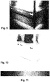
- the processed lower temperature grayscale image is then colourised with the first colourmap to obtain a colourised and processed lower temperature image. A grayscale version of that image is shown in Figure 9 .
- the second colourmap is used to maximise metric data value estimation, i.e. the capacity of the user to estimate the value (here temperature) of a specific part of the image. This is implemented by maximising the number of perceptually distinct colour sectors (just-noticeable difference (JND)) in the second colourmap but with all colours sharing similar equal visual importance. It is estimated that in firefighting applications, a ⁇ 10°C approximation is acceptable in a temperature range between 80°C and 680°C. It corresponds to 60 separate colour sectors. Also the second colourmap can be visually represented by a line comprising a given number of connected colour points (in this example 256) each having a different colour value.
- the second colourmap is in this example built around 4 distinct main colours and interpolated linearly between these colours, selected in such a way to achieve JNDs > 60. These main colours from left to right are in this example white, yellow, orange and red.
- a grayscale version of a colourised and processed higher temperature image is shown in Figure 10 . This image is obtained by colourising the processed higher temperature grayscale image with the second colourmap.
- the first and second colourmaps can be combined to obtain a nested or combined colourmap consisting of the first and second colourmaps as shown in Figure 11 , the first colourmap being the left half of the nested colourmap, while the right half is the second colourmap.
- the first and second colourmaps are connected in such a manner that the connecting colour values of the first and second colourmaps have substantially the same chromaticity and lightness values.
- first and second colourmaps it is not necessary to physically connect or combine the first and second colourmaps, but preferably a colour value at one end of the first colourmap has lightness and chromaticity values which are the same as the ones of a colour value at one end of the second colourmap to provide a seamless link between the two colourmaps and thus to avoid artefacts in the image.
- the first and second colourmaps can be said to be static in the sense that they remain constant for multiple thermal frames, for example for the entire duration of one or more videos consisting of a set of consecutive image frames.
- the two colour images are then combined or blended using an alpha mask shown in Figure 12 .
- the alpha mask which is a binary image or matrix of the same size as the original temperature matrix, is derived from the original thermal frame so that the temperature values higher than the threshold temperature are given a first value, while the temperature values smaller than or equal to the threshold temperature are a second, different value. More specifically, the image element or pixel values of the alpha mask are either 0 or 1. In this example, pixel values of the alpha mask are 1 wherever the temperature values in the original thermal frame are above the temperature threshold, which in this example is 80°C. Other pixel values in the alpha mask are set to 0.
- the alpha mask indicates how the colourised and processed higher temperature image should be superimposed on the colourised and processed lower temperature image.
- the values 1 in the alpha mask indicate the pixel locations where the colourised and processed higher temperature image should replace the pixels of the colourised and processed lower temperature image.
- the blended image may be obtained as a completely new image starting from the colourised lower and higher temperature images.
- Figure 13 shows a grayscale version of the final blended colour image.
- the automatic brightness or luminosity control process is next explained in more detail.
- the luminosity of the display and its corresponding luminance is adapted to the luminance of the background such that both the visible background and thermal overlay information are understandable.
- Luminosity is defined as the total light emitted by the full display module, and more specifically the total light emitted by the backlight drive.
- luminance is defined by how much luminous energy is detected by a human eye when looking at a surface (either the background or the display) at a given angle of view. It defines how bright the surface looks.
- the display and the background need to keep a fixed luminance ratio if it is desired that the screen always appears "equally" bright.
- the luminosity or luminance adaptation is implemented by using an integrated or separate backlight in the display 9 and the forward-looking luminosity sensor 7. In order to find the right parameters for their relation, both the display 9 and luminosity sensor 7 are first characterised.
- the automatic brightness control is optionally also responsible for adapting the luminance of the display depending on the scene's (image's) information value.
- This value may be determined by the total dynamic range of the original thermal frame.
- a low dynamic range typically implies a final thermal image with low information value, e.g. when the user is looking directly at a wall having only a very limited temperature range.
- the luminance (or brightness) of the display is adapted in such a way that the display or the displayed image is seen as more transparent.
- the scene information value is computed to stay within [0:1] range.
- the full automatic brightness control algorithm is described in Algorithm 2 below.
- the target luminance ratio lum ratio (the display luminance divided by the scene luminance) is first calculated by multiplying the scene information value with the upper ratio threshold ratio high . It is then determined whether or not the obtained value is under the lower ratio threshold ratio low , and if it is, then the lum ratio is set it to this threshold value.
- the screen luminance lum screen is then calculated by multiplying the lum ratio with the measured scene luminance lum scene . Now the screen luminance is compared with the two absolute thresholds backlight low and backlight high , and set it to one of these boundary values if the screen luminance would otherwise be lower than backlight low or higher than backlight high .
- the lum ratio varies depending on the scene information value. In this example, scene information values between the lower and upper thresholds result in linearly increasing display backlight drive values.
- step 101 the original thermal frame is obtained by using the thermal camera 5.
- the original thermal frame is made available by the thermal camera 5 as a temperature matrix with a high dynamic range DR H .
- step 103 three matrices of the same size and shape as the original temperature matrix are generated from the original temperature matrix obtained in step 101:
- step 105 the histogram, referred to as the input histogram, for the lower temperature matrix is generated.
- step 107 the input histogram is equalised as explained above to obtain the equalised output histogram.
- step 109 the contrast enhanced lower temperature grayscale image is generated from the equalised histogram and from the lower temperature matrix TM L .
- the lower temperature matrix TM L is non-linearly mapped to the lower temperature grayscale image with a short dynamic range DR S by using the histogram equalisation technique. This process also leads to obtaining a modified lower temperature matrix so that the lower temperature image can be derived from the modified lower temperature matrix.
- step 111 the lower temperature grayscale image is colourised by using the first colourmap to obtain the lower temperature colour image C L .
- step 113 the higher temperature matrix TM H is linearly mapped to the higher temperature grayscale image with a short dynamic range DR S . This involves obtaining a modified higher temperature matrix so that the higher temperature grayscale image can be derived from the modified higher temperature matrix.
- step 115 the higher temperature grayscale image is colourised by using the second colourmap to obtain the higher temperature colour image C H .
- step 119 the combined colour image C F is transmitted either wirelessly or through a cable to the display 9.
- step 121 the value of the display backlight drive is determined based on the scene's information value derived from the original input thermal frame and/or luminosity sensor input value.
- step 123 the combined colour image C F is displayed on the see-through display 9 with the display backlight drive set to the value determined in step 121.
Landscapes
- Engineering & Computer Science (AREA)
- Physics & Mathematics (AREA)
- General Physics & Mathematics (AREA)
- Theoretical Computer Science (AREA)
- Multimedia (AREA)
- Signal Processing (AREA)
- Computer Hardware Design (AREA)
- Optics & Photonics (AREA)
- Controls And Circuits For Display Device (AREA)
- Control Of Indicators Other Than Cathode Ray Tubes (AREA)
- Image Processing (AREA)
Claims (15)
- Verfahren zum Anzeigen eines Bildes auf einer durchsichtigen Anzeige (9), wobei das Verfahren Folgendes umfasst:• Erhalten (101) einer ersten Matrix elektromagnetischer Strahlung eines Objekts, wobei die erste Matrix erste Matrixelemente umfasst, die Strahlungsintensitätswerte entsprechender Orte des Objekts darstellen;• Unterteilen (103) der ersten Matrix in eine zweite Matrix, die eine erste Teilmenge der Strahlungsintensitätswerte der Matrixelemente darstellt, und eine dritte unterschiedliche Matrix, die eine zweite unterschiedliche Teilmenge der Strahlungsintensitätswerte der Matrixelemente darstellt;• Erzeugen (105) eines ersten Histogramms für die zweite Matrix;• Ausgleichen (107) des ersten Histogramms, um ein ausgeglichenes zweites Histogramm zu erhalten;• Erzeugen (109) eines ersten Graustufenbildes, das die erste Teilmenge der Strahlungsintensitätswerte aus der zweiten Matrix und dem ausgeglichenen zweiten Histogramm darstellt;• Färben (111) des ersten Graustufenbildes mit einer ersten Farbkarte, um ein erstes Farbbild zu erhalten;• Erzeugen (113) eines zweiten Graustufenbildes, das die zweite Teilmenge der Strahlungsintensitätswerte darstellt, durch im Wesentlichen lineares Zuordnen der zweiten Teilmenge der Strahlungsintensitätswerte zu einer gegebenen Anzahl von codierten Strahlungsintensitätswerten;• Färben (115) des zweiten Graustufenbildes mit einer zweiten Farbkarte, die sich von der ersten Farbkarte unterscheidet, um ein zweites Farbbild zu erhalten;• Kombinieren (117) des ersten Farbbildes und des zweiten Farbbildes, um ein kombiniertes Farbbild derselben Größe und Form wie das erste Farbbild oder das zweite Farbbild zu erhalten; und• Anzeigen (123) des kombinierten Farbbildes auf der durchsichtigen Anzeige (9).
- Verfahren nach Anspruch 1, wobei die Strahlungsintensitätswerte der zweiten Matrix gleich oder kleiner als ein Schwellenwert sind und die Strahlungsintensitätswerte der dritten Matrix höher als der Schwellenwert sind oder umgekehrt.
- Verfahren nach einem der vorhergehenden Ansprüche, wobei die elektromagnetische Strahlung Wärmestrahlung ist.
- Verfahren nach einem der vorhergehenden Ansprüche, wobei die erste Farbkarte und die zweite Farbkarte eine erste Farbnachschlagetabelle beziehungsweise eine zweite Farbnachschlagetabelle derart definieren, dass die erste und die zweite Farbnachschlagetabelle jeweils n eindeutige Farbwerte umfassen, wobei n der gegebenen Anzahl von codierten Strahlungsintensitätswerten entspricht.
- Verfahren nach Anspruch 4, wobei die n eindeutigen Farbwerte der zweiten Farbkarte jeweils einzeln für das menschliche Auge erkennbar sind.
- Verfahren nach einem der vorhergehenden Ansprüche, wobei die erste Farbkarte Farbwerte umfasst, deren Helligkeits- und Farbartwerte im Wesentlichen linear von einem ersten Ende der Farbkarte zu einem zweiten, gegenüberliegenden Ende der Farbkarte zunehmen.
- Verfahren nach einem der vorhergehenden Ansprüche, wobei ein erster Farbwert an einem Ende der ersten Farbkarte einen ersten Helligkeitswert und einen ersten Farbartwert aufweist, während ein zweiter Farbwert an einem Ende der zweiten Farbkarte einen zweiten Helligkeitswert und einen zweiten Farbartwert aufweist, und wobei der erste Helligkeitswert im Wesentlichen der gleiche wie der zweite Helligkeitswert ist und der erste Farbartwert im Wesentlichen der gleiche wie der zweite Farbartwert ist.
- Verfahren nach einem der vorhergehenden Ansprüche, wobei die erste Farbkarte eine einfarbige Farbkarte ist, wohingegen die zweite Farbkarte eine mehrfarbige Farbkarte ist.
- Verfahren nach einem der vorhergehenden Ansprüche, wobei das Objekt für das menschliche Auge nicht sichtbar ist.
- Verfahren nach einem der vorhergehenden Ansprüche, wobei das Verfahren ferner das Erzeugen einer binären vierten Matrix mit der gleichen Größe und Form wie die erste Matrix, wobei die vierte Matrix vierte Matrixelemente umfasst, die für jeden von Null verschiedenen Wert der dritten Matrix auf 1 gesetzt sind und die anderen vierten Matrixelemente auf 0 gesetzt sind oder umgekehrt, und ein Verwenden der vierten Matrix, um das erste und das zweite Farbbild zu kombinieren, umfasst.
- Verfahren nach einem der vorhergehenden Ansprüche, wobei das erste Histogramm erste Histogrammurnen umfasst, während das zweite Histogramm zweite Histogrammurnen umfasst, und wobei das Ausgleichen des ersten Histogramms ein Zuweisen von Bildelementen der ersten Histogrammurnen zu den zweiten Histogrammurnen derart umfasst, dass die gesamten Bildelemente einer einzelnen ersten Histogrammurne einer zweiten Histogrammurne derart zugewiesen werden, dass ein Füllen einer speziellen zweiten Histogrammurne mit den Bildelementen der ersten Histogrammurne gestoppt wird, sobald wenigstens eines der folgenden Ereignisse erfolgt:• eine Anzahl von Bildelementen in dieser speziellen zweiten Histogrammurne erreicht einen zweiten Schwellenwert; und• eine Anzahl unterschiedlicher erster Histogrammurnen, die verwendet werden, um diese spezielle zweite Histogrammurne zu füllen, erreicht einen dritten Schwellenwert.
- Verfahren nach einem der vorhergehenden Ansprüche, wobei das Verfahren ferner das Anpassen (121) der Leuchtdichte der durchsichtigen Anzeige (9) basierend auf der Objekthintergrundleuchtdichte und/oder einem Informationsgehalt der ersten Matrix umfasst.
- Verfahren nach Anspruch 12, wobei das Verfahren ferner das Bestimmen der Objekthintergrundleuchtdichte und ein Halten eines Verhältnisses von "Anzeigeleuchtdichte" zu "Objekthintergrundleuchtdichte" im Wesentlichen konstant umfasst.
- Verfahren nach Anspruch 12, wobei das Verfahren ferner das Bestimmen der Objekthintergrundleuchtdichte und das Variieren eines Verhältnisses von "Anzeigeleuchtdichte" zu "Objekthintergrundleuchtdichte" zwischen einer unteren Schwelle und einer höheren Schwelle in Abhängigkeit von dem Informationsgehalt der ersten Matrix umfasst, wobei die untere Schwelle einem niedrigen Informationsgehalt entspricht, während die höhere Schwelle einem normalen Informationsgehalt entspricht.
- Bildgebungssystem zum Anzeigen eines Bildes auf einer durchsichtigen Anzeige (9), wobei das System Mittel für Folgendes umfasst:• Erhalten einer ersten Matrix elektromagnetischer Strahlung eines Objekts, wobei die erste Matrix erste Matrixelemente umfasst, die Strahlungsintensitätswerte entsprechender Orte des Objekts darstellen;• Unterteilen der ersten Matrix in eine zweite Matrix, die eine erste Teilmenge der Strahlungsintensitätswerte der Matrixelemente darstellt, und eine dritte unterschiedliche Matrix, die eine zweite unterschiedliche Teilmenge der Strahlungsintensitätswerte der Matrixelemente darstellt;• Erzeugen eines ersten Histogramms für die zweite Matrix;• Ausgleichen des ersten Histogramms, um ein ausgeglichenes zweites Histogramm zu erhalten;• Erzeugen eines ersten Graustufenbildes, das die erste Teilmenge der Strahlungsintensitätswerte aus der zweiten Matrix und dem ausgeglichenen zweiten Histogramm darstellt;• Färben des ersten Graustufenbildes mit einer ersten Farbkarte, um ein erstes Farbbild zu erhalten;• Erzeugen eines zweiten Graustufenbildes, das die zweite Teilmenge der Strahlungsintensitätswerte darstellt, durch im Wesentlichen lineares Zuordnen der zweiten Teilmenge der Strahlungsintensitätswerte zu einer gegebenen Anzahl von codierten Strahlungsintensitätswerten;• Färben des zweiten Graustufenbildes mit einer zweiten Farbkarte, die sich von der ersten Farbkarte unterscheidet, um ein zweites Farbbild zu erhalten;• Kombinieren des ersten Farbbildes und des zweiten Farbbildes, um ein kombiniertes Farbbild derselben Größe und Form wie das erste Farbbild oder das zweite Farbbild zu erhalten; und• Anzeigen des kombinierten Farbbildes auf der durchsichtigen Anzeige (9).
Applications Claiming Priority (1)
| Application Number | Priority Date | Filing Date | Title |
|---|---|---|---|
| PCT/EP2017/083934 WO2019120525A1 (en) | 2017-12-20 | 2017-12-20 | Method of displaying an image on a see-through display |
Publications (2)
| Publication Number | Publication Date |
|---|---|
| EP3729366A1 EP3729366A1 (de) | 2020-10-28 |
| EP3729366B1 true EP3729366B1 (de) | 2021-08-25 |
Family
ID=60957282
Family Applications (1)
| Application Number | Title | Priority Date | Filing Date |
|---|---|---|---|
| EP17828899.9A Active EP3729366B1 (de) | 2017-12-20 | 2017-12-20 | Verfahren zum anzeigen eines bildes auf einer durchsichtigen anzeige |
Country Status (7)
| Country | Link |
|---|---|
| US (2) | US10984563B2 (de) |
| EP (1) | EP3729366B1 (de) |
| CN (1) | CN111465961B (de) |
| AU (1) | AU2017443546B2 (de) |
| CA (1) | CA3086070C (de) |
| SG (1) | SG11202005384QA (de) |
| WO (1) | WO2019120525A1 (de) |
Families Citing this family (7)
| Publication number | Priority date | Publication date | Assignee | Title |
|---|---|---|---|---|
| CA3086070C (en) * | 2017-12-20 | 2021-02-09 | Adrien Birbaumer | Method of displaying an image on a see-through display |
| SG11202004924VA (en) | 2018-01-24 | 2020-06-29 | Darix Sarl | Head-mountable augmented vision system for displaying thermal images |
| EP3847616A4 (de) * | 2018-09-06 | 2022-05-18 | Carmel Haifa University Economic Corporation Ltd. | Modellfreie auf physik basierte rekonstruktion von in streuenden medien aufgenommenen bildern |
| DE102020100929A1 (de) | 2020-01-16 | 2021-07-22 | Vhf Elektronik Gmbh | Wärmebild-Be- oder Verarbeitungsverfahren |
| CN111568549B (zh) * | 2020-05-28 | 2025-02-14 | 维景医疗科技(浙江)有限公司 | 一种具有实时成像功能的可视化系统 |
| HUP2400396A1 (hu) | 2024-08-27 | 2026-02-28 | Bukvai Károly Péter | Rendszerek és eljárások virtuális kép valós idejű illesztésére kiterjesztett valóság kijelzőn |
| CN119515701B (zh) * | 2025-01-15 | 2025-04-15 | 南京正泽科技股份有限公司 | 一种基于消防面罩的多模态图像融合方法及消防面罩 |
Family Cites Families (15)
| Publication number | Priority date | Publication date | Assignee | Title |
|---|---|---|---|---|
| US6463173B1 (en) * | 1995-10-30 | 2002-10-08 | Hewlett-Packard Company | System and method for histogram-based image contrast enhancement |
| US6255650B1 (en) | 1998-12-11 | 2001-07-03 | Flir Systems, Inc. | Extreme temperature radiometry and imaging apparatus |
| EP1107041B2 (de) | 1999-12-03 | 2012-11-14 | active photonics AG, Visualisierungs- und Kommunikationssysteme | Maske zum Anzeigen von mit einer Kamera aufgenommenen Bildern |
| CN1221833C (zh) | 1999-12-09 | 2005-10-05 | 激活光子学观测和通信系统股份公司 | 带有用于显示图像的屏幕的装置 |
| US7369174B2 (en) | 2001-12-27 | 2008-05-06 | Sage Technologies Ltd. | Helmet-mounted thermal imaging system |
| CA2662916A1 (en) * | 2006-09-11 | 2008-03-20 | Bruce Hodge | Thermally gradient target |
| US8817106B2 (en) | 2007-11-28 | 2014-08-26 | Flir Systems, Inc. | Infrared camera with image processing modes for maritime applications |
| EP2829056B1 (de) | 2012-03-19 | 2019-10-16 | Flir Systems, Inc. | Tragbare vorrichtung mit einem integrierten infrarotbildgebungsmodul |
| US9998687B2 (en) | 2012-09-12 | 2018-06-12 | Bae Systems Information And Electronic Systems Integration Inc. | Face mounted extreme environment thermal sensor system |
| US9989623B2 (en) * | 2013-06-13 | 2018-06-05 | Basf Se | Detector for determining a longitudinal coordinate of an object via an intensity distribution of illuminated pixels |
| CN103354616A (zh) * | 2013-07-05 | 2013-10-16 | 南京大学 | 在平面显示器上实现立体显示的方法和系统 |
| US10298859B2 (en) * | 2013-11-01 | 2019-05-21 | Flir Systems Ab | Enhanced visual representation of infrared data values |
| US10089787B2 (en) * | 2013-12-26 | 2018-10-02 | Flir Systems Ab | Systems and methods for displaying infrared images |
| CN106773042B (zh) * | 2016-12-16 | 2022-03-25 | 联想(北京)有限公司 | 复合显示器、显示控制方法及穿戴式设备 |
| CA3086070C (en) | 2017-12-20 | 2021-02-09 | Adrien Birbaumer | Method of displaying an image on a see-through display |
-
2017
- 2017-12-20 CA CA3086070A patent/CA3086070C/en active Active
- 2017-12-20 SG SG11202005384QA patent/SG11202005384QA/en unknown
- 2017-12-20 WO PCT/EP2017/083934 patent/WO2019120525A1/en not_active Ceased
- 2017-12-20 CN CN201780097586.XA patent/CN111465961B/zh not_active Expired - Fee Related
- 2017-12-20 AU AU2017443546A patent/AU2017443546B2/en not_active Ceased
- 2017-12-20 US US16/767,669 patent/US10984563B2/en active Active
- 2017-12-20 EP EP17828899.9A patent/EP3729366B1/de active Active
-
2021
- 2021-03-15 US US17/201,773 patent/US11232609B2/en not_active Expired - Fee Related
Also Published As
| Publication number | Publication date |
|---|---|
| US20200380735A1 (en) | 2020-12-03 |
| AU2017443546A1 (en) | 2020-07-09 |
| CN111465961B (zh) | 2021-03-05 |
| WO2019120525A1 (en) | 2019-06-27 |
| CN111465961A (zh) | 2020-07-28 |
| EP3729366A1 (de) | 2020-10-28 |
| US11232609B2 (en) | 2022-01-25 |
| CA3086070A1 (en) | 2019-06-27 |
| CA3086070C (en) | 2021-02-09 |
| US20210225045A1 (en) | 2021-07-22 |
| US10984563B2 (en) | 2021-04-20 |
| AU2017443546B2 (en) | 2020-07-16 |
| SG11202005384QA (en) | 2020-07-29 |
Similar Documents
| Publication | Publication Date | Title |
|---|---|---|
| US11232609B2 (en) | Method of displaying an image on a see-through display | |
| US10373583B2 (en) | Image transforming vision enhancement device | |
| US10636368B2 (en) | Image display apparatus and method for controlling same | |
| US10446092B2 (en) | Image processing apparatus, display apparatus, image processing method, and image processing program | |
| JP5897159B2 (ja) | 表示装置及びその制御方法 | |
| US8311328B2 (en) | Electronic vision aid and electronic vision aid method | |
| US20120269431A1 (en) | Methods and appartuses for restoring color and enhancing electronic images | |
| CN107295248A (zh) | 显示图像的图像显示设备和图像显示方法及存储介质 | |
| TW200826058A (en) | A color mapping method | |
| EP1819143A1 (de) | Farbjustierungseinrichtung und -verfahren | |
| US8781246B2 (en) | Image enhancement | |
| CN1957603B (zh) | 视频信号变换装置、视频显示装置 | |
| CN101268700A (zh) | 在视频上叠加字符的方法和设备 | |
| US11410274B2 (en) | Information processing device and program | |
| KR100446618B1 (ko) | 영상 표시 장치에서의 사용자 선호 색온도 변환 방법 및장치 | |
| US7961939B2 (en) | Color transforming method | |
| JP6532103B2 (ja) | 映像表示装置およびテレビ受信装置 | |
| US20170110071A1 (en) | Image display apparatus and color conversion apparatus | |
| JP2015138108A (ja) | 表示装置及び画質調整装置 | |
| US20070133867A1 (en) | Apparatus and method of adaptively converting image in image display system | |
| JP5476108B2 (ja) | 表示装置 | |
| WO2016136175A1 (en) | Image display apparatus and method for controlling same | |
| KR100922723B1 (ko) | 디스플레이 소자에 있어서 명도 및 채도 개선 장치 및 이를수행하기 위한 방법 | |
| JP2020190711A (ja) | 画像処理装置および画像処理方法 | |
| CN120742545A (zh) | 显示方法、显示系统和车辆 |
Legal Events
| Date | Code | Title | Description |
|---|---|---|---|
| STAA | Information on the status of an ep patent application or granted ep patent |
Free format text: STATUS: UNKNOWN |
|
| STAA | Information on the status of an ep patent application or granted ep patent |
Free format text: STATUS: THE INTERNATIONAL PUBLICATION HAS BEEN MADE |
|
| PUAI | Public reference made under article 153(3) epc to a published international application that has entered the european phase |
Free format text: ORIGINAL CODE: 0009012 |
|
| STAA | Information on the status of an ep patent application or granted ep patent |
Free format text: STATUS: REQUEST FOR EXAMINATION WAS MADE |
|
| 17P | Request for examination filed |
Effective date: 20200622 |
|
| AK | Designated contracting states |
Kind code of ref document: A1 Designated state(s): AL AT BE BG CH CY CZ DE DK EE ES FI FR GB GR HR HU IE IS IT LI LT LU LV MC MK MT NL NO PL PT RO RS SE SI SK SM TR |
|
| AX | Request for extension of the european patent |
Extension state: BA ME |
|
| RAP1 | Party data changed (applicant data changed or rights of an application transferred) |
Owner name: ECOLE POLYTECHNIQUE FEDERALE DE LAUSANNE (EPFL) |
|
| DAV | Request for validation of the european patent (deleted) | ||
| DAX | Request for extension of the european patent (deleted) | ||
| GRAP | Despatch of communication of intention to grant a patent |
Free format text: ORIGINAL CODE: EPIDOSNIGR1 |
|
| STAA | Information on the status of an ep patent application or granted ep patent |
Free format text: STATUS: GRANT OF PATENT IS INTENDED |
|
| INTG | Intention to grant announced |
Effective date: 20210416 |
|
| GRAS | Grant fee paid |
Free format text: ORIGINAL CODE: EPIDOSNIGR3 |
|
| GRAA | (expected) grant |
Free format text: ORIGINAL CODE: 0009210 |
|
| STAA | Information on the status of an ep patent application or granted ep patent |
Free format text: STATUS: THE PATENT HAS BEEN GRANTED |
|
| AK | Designated contracting states |
Kind code of ref document: B1 Designated state(s): AL AT BE BG CH CY CZ DE DK EE ES FI FR GB GR HR HU IE IS IT LI LT LU LV MC MK MT NL NO PL PT RO RS SE SI SK SM TR |
|
| REG | Reference to a national code |
Ref country code: CH Ref legal event code: EP |
|
| REG | Reference to a national code |
Ref country code: IE Ref legal event code: FG4D Ref country code: AT Ref legal event code: REF Ref document number: 1424554 Country of ref document: AT Kind code of ref document: T Effective date: 20210915 |
|
| REG | Reference to a national code |
Ref country code: DE Ref legal event code: R096 Ref document number: 602017044867 Country of ref document: DE |
|
| REG | Reference to a national code |
Ref country code: NL Ref legal event code: FP |
|
| REG | Reference to a national code |
Ref country code: LT Ref legal event code: MG9D |
|
| REG | Reference to a national code |
Ref country code: AT Ref legal event code: MK05 Ref document number: 1424554 Country of ref document: AT Kind code of ref document: T Effective date: 20210825 |
|
| PG25 | Lapsed in a contracting state [announced via postgrant information from national office to epo] |
Ref country code: RS Free format text: LAPSE BECAUSE OF FAILURE TO SUBMIT A TRANSLATION OF THE DESCRIPTION OR TO PAY THE FEE WITHIN THE PRESCRIBED TIME-LIMIT Effective date: 20210825 Ref country code: SE Free format text: LAPSE BECAUSE OF FAILURE TO SUBMIT A TRANSLATION OF THE DESCRIPTION OR TO PAY THE FEE WITHIN THE PRESCRIBED TIME-LIMIT Effective date: 20210825 Ref country code: FI Free format text: LAPSE BECAUSE OF FAILURE TO SUBMIT A TRANSLATION OF THE DESCRIPTION OR TO PAY THE FEE WITHIN THE PRESCRIBED TIME-LIMIT Effective date: 20210825 Ref country code: ES Free format text: LAPSE BECAUSE OF FAILURE TO SUBMIT A TRANSLATION OF THE DESCRIPTION OR TO PAY THE FEE WITHIN THE PRESCRIBED TIME-LIMIT Effective date: 20210825 Ref country code: HR Free format text: LAPSE BECAUSE OF FAILURE TO SUBMIT A TRANSLATION OF THE DESCRIPTION OR TO PAY THE FEE WITHIN THE PRESCRIBED TIME-LIMIT Effective date: 20210825 Ref country code: AT Free format text: LAPSE BECAUSE OF FAILURE TO SUBMIT A TRANSLATION OF THE DESCRIPTION OR TO PAY THE FEE WITHIN THE PRESCRIBED TIME-LIMIT Effective date: 20210825 Ref country code: BG Free format text: LAPSE BECAUSE OF FAILURE TO SUBMIT A TRANSLATION OF THE DESCRIPTION OR TO PAY THE FEE WITHIN THE PRESCRIBED TIME-LIMIT Effective date: 20211125 Ref country code: LT Free format text: LAPSE BECAUSE OF FAILURE TO SUBMIT A TRANSLATION OF THE DESCRIPTION OR TO PAY THE FEE WITHIN THE PRESCRIBED TIME-LIMIT Effective date: 20210825 Ref country code: PT Free format text: LAPSE BECAUSE OF FAILURE TO SUBMIT A TRANSLATION OF THE DESCRIPTION OR TO PAY THE FEE WITHIN THE PRESCRIBED TIME-LIMIT Effective date: 20211227 Ref country code: NO Free format text: LAPSE BECAUSE OF FAILURE TO SUBMIT A TRANSLATION OF THE DESCRIPTION OR TO PAY THE FEE WITHIN THE PRESCRIBED TIME-LIMIT Effective date: 20211125 |
|
| PG25 | Lapsed in a contracting state [announced via postgrant information from national office to epo] |
Ref country code: PL Free format text: LAPSE BECAUSE OF FAILURE TO SUBMIT A TRANSLATION OF THE DESCRIPTION OR TO PAY THE FEE WITHIN THE PRESCRIBED TIME-LIMIT Effective date: 20210825 Ref country code: LV Free format text: LAPSE BECAUSE OF FAILURE TO SUBMIT A TRANSLATION OF THE DESCRIPTION OR TO PAY THE FEE WITHIN THE PRESCRIBED TIME-LIMIT Effective date: 20210825 Ref country code: GR Free format text: LAPSE BECAUSE OF FAILURE TO SUBMIT A TRANSLATION OF THE DESCRIPTION OR TO PAY THE FEE WITHIN THE PRESCRIBED TIME-LIMIT Effective date: 20211126 |
|
| PG25 | Lapsed in a contracting state [announced via postgrant information from national office to epo] |
Ref country code: DK Free format text: LAPSE BECAUSE OF FAILURE TO SUBMIT A TRANSLATION OF THE DESCRIPTION OR TO PAY THE FEE WITHIN THE PRESCRIBED TIME-LIMIT Effective date: 20210825 |
|
| REG | Reference to a national code |
Ref country code: DE Ref legal event code: R097 Ref document number: 602017044867 Country of ref document: DE |
|
| PG25 | Lapsed in a contracting state [announced via postgrant information from national office to epo] |
Ref country code: SM Free format text: LAPSE BECAUSE OF FAILURE TO SUBMIT A TRANSLATION OF THE DESCRIPTION OR TO PAY THE FEE WITHIN THE PRESCRIBED TIME-LIMIT Effective date: 20210825 Ref country code: SK Free format text: LAPSE BECAUSE OF FAILURE TO SUBMIT A TRANSLATION OF THE DESCRIPTION OR TO PAY THE FEE WITHIN THE PRESCRIBED TIME-LIMIT Effective date: 20210825 Ref country code: RO Free format text: LAPSE BECAUSE OF FAILURE TO SUBMIT A TRANSLATION OF THE DESCRIPTION OR TO PAY THE FEE WITHIN THE PRESCRIBED TIME-LIMIT Effective date: 20210825 Ref country code: EE Free format text: LAPSE BECAUSE OF FAILURE TO SUBMIT A TRANSLATION OF THE DESCRIPTION OR TO PAY THE FEE WITHIN THE PRESCRIBED TIME-LIMIT Effective date: 20210825 Ref country code: CZ Free format text: LAPSE BECAUSE OF FAILURE TO SUBMIT A TRANSLATION OF THE DESCRIPTION OR TO PAY THE FEE WITHIN THE PRESCRIBED TIME-LIMIT Effective date: 20210825 Ref country code: AL Free format text: LAPSE BECAUSE OF FAILURE TO SUBMIT A TRANSLATION OF THE DESCRIPTION OR TO PAY THE FEE WITHIN THE PRESCRIBED TIME-LIMIT Effective date: 20210825 |
|
| PLBE | No opposition filed within time limit |
Free format text: ORIGINAL CODE: 0009261 |
|
| STAA | Information on the status of an ep patent application or granted ep patent |
Free format text: STATUS: NO OPPOSITION FILED WITHIN TIME LIMIT |
|
| PG25 | Lapsed in a contracting state [announced via postgrant information from national office to epo] |
Ref country code: MC Free format text: LAPSE BECAUSE OF FAILURE TO SUBMIT A TRANSLATION OF THE DESCRIPTION OR TO PAY THE FEE WITHIN THE PRESCRIBED TIME-LIMIT Effective date: 20210825 Ref country code: IT Free format text: LAPSE BECAUSE OF FAILURE TO SUBMIT A TRANSLATION OF THE DESCRIPTION OR TO PAY THE FEE WITHIN THE PRESCRIBED TIME-LIMIT Effective date: 20210825 |
|
| 26N | No opposition filed |
Effective date: 20220527 |
|
| REG | Reference to a national code |
Ref country code: BE Ref legal event code: MM Effective date: 20211231 |
|
| PG25 | Lapsed in a contracting state [announced via postgrant information from national office to epo] |
Ref country code: LU Free format text: LAPSE BECAUSE OF NON-PAYMENT OF DUE FEES Effective date: 20211220 Ref country code: IE Free format text: LAPSE BECAUSE OF NON-PAYMENT OF DUE FEES Effective date: 20211220 |
|
| PG25 | Lapsed in a contracting state [announced via postgrant information from national office to epo] |
Ref country code: BE Free format text: LAPSE BECAUSE OF NON-PAYMENT OF DUE FEES Effective date: 20211231 |
|
| PGFP | Annual fee paid to national office [announced via postgrant information from national office to epo] |
Ref country code: NL Payment date: 20221121 Year of fee payment: 6 Ref country code: GB Payment date: 20221121 Year of fee payment: 6 Ref country code: FR Payment date: 20221118 Year of fee payment: 6 Ref country code: DE Payment date: 20221121 Year of fee payment: 6 |
|
| PGFP | Annual fee paid to national office [announced via postgrant information from national office to epo] |
Ref country code: CH Payment date: 20230101 Year of fee payment: 6 |
|
| P01 | Opt-out of the competence of the unified patent court (upc) registered |
Effective date: 20230523 |
|
| PG25 | Lapsed in a contracting state [announced via postgrant information from national office to epo] |
Ref country code: CY Free format text: LAPSE BECAUSE OF FAILURE TO SUBMIT A TRANSLATION OF THE DESCRIPTION OR TO PAY THE FEE WITHIN THE PRESCRIBED TIME-LIMIT Effective date: 20210825 |
|
| PG25 | Lapsed in a contracting state [announced via postgrant information from national office to epo] |
Ref country code: HU Free format text: LAPSE BECAUSE OF FAILURE TO SUBMIT A TRANSLATION OF THE DESCRIPTION OR TO PAY THE FEE WITHIN THE PRESCRIBED TIME-LIMIT; INVALID AB INITIO Effective date: 20171220 |
|
| PG25 | Lapsed in a contracting state [announced via postgrant information from national office to epo] |
Ref country code: SI Free format text: LAPSE BECAUSE OF FAILURE TO SUBMIT A TRANSLATION OF THE DESCRIPTION OR TO PAY THE FEE WITHIN THE PRESCRIBED TIME-LIMIT Effective date: 20210825 |
|
| PG25 | Lapsed in a contracting state [announced via postgrant information from national office to epo] |
Ref country code: MK Free format text: LAPSE BECAUSE OF FAILURE TO SUBMIT A TRANSLATION OF THE DESCRIPTION OR TO PAY THE FEE WITHIN THE PRESCRIBED TIME-LIMIT Effective date: 20210825 |
|
| REG | Reference to a national code |
Ref country code: DE Ref legal event code: R119 Ref document number: 602017044867 Country of ref document: DE |
|
| REG | Reference to a national code |
Ref country code: CH Ref legal event code: PL |
|
| REG | Reference to a national code |
Ref country code: NL Ref legal event code: MM Effective date: 20240101 |
|
| GBPC | Gb: european patent ceased through non-payment of renewal fee |
Effective date: 20231220 |
|
| PG25 | Lapsed in a contracting state [announced via postgrant information from national office to epo] |
Ref country code: NL Free format text: LAPSE BECAUSE OF NON-PAYMENT OF DUE FEES Effective date: 20240101 |
|
| PG25 | Lapsed in a contracting state [announced via postgrant information from national office to epo] |
Ref country code: MT Free format text: LAPSE BECAUSE OF FAILURE TO SUBMIT A TRANSLATION OF THE DESCRIPTION OR TO PAY THE FEE WITHIN THE PRESCRIBED TIME-LIMIT Effective date: 20210825 Ref country code: NL Free format text: LAPSE BECAUSE OF NON-PAYMENT OF DUE FEES Effective date: 20240101 |
|
| PG25 | Lapsed in a contracting state [announced via postgrant information from national office to epo] |
Ref country code: DE Free format text: LAPSE BECAUSE OF NON-PAYMENT OF DUE FEES Effective date: 20240702 |
|
| PG25 | Lapsed in a contracting state [announced via postgrant information from national office to epo] |
Ref country code: GB Free format text: LAPSE BECAUSE OF NON-PAYMENT OF DUE FEES Effective date: 20231220 |
|
| PG25 | Lapsed in a contracting state [announced via postgrant information from national office to epo] |
Ref country code: FR Free format text: LAPSE BECAUSE OF NON-PAYMENT OF DUE FEES Effective date: 20231231 |
|
| PG25 | Lapsed in a contracting state [announced via postgrant information from national office to epo] |
Ref country code: CH Free format text: LAPSE BECAUSE OF NON-PAYMENT OF DUE FEES Effective date: 20231231 |
|
| PG25 | Lapsed in a contracting state [announced via postgrant information from national office to epo] |
Ref country code: GB Free format text: LAPSE BECAUSE OF NON-PAYMENT OF DUE FEES Effective date: 20231220 Ref country code: FR Free format text: LAPSE BECAUSE OF NON-PAYMENT OF DUE FEES Effective date: 20231231 Ref country code: DE Free format text: LAPSE BECAUSE OF NON-PAYMENT OF DUE FEES Effective date: 20240702 Ref country code: CH Free format text: LAPSE BECAUSE OF NON-PAYMENT OF DUE FEES Effective date: 20231231 |
|
| PG25 | Lapsed in a contracting state [announced via postgrant information from national office to epo] |
Ref country code: TR Free format text: LAPSE BECAUSE OF FAILURE TO SUBMIT A TRANSLATION OF THE DESCRIPTION OR TO PAY THE FEE WITHIN THE PRESCRIBED TIME-LIMIT Effective date: 20210825 |