EP3729486B1 - Système de contrôle thermique homogène électriquement découplé d'une électrode au moyen de tubes thermoconducteurs et installation de traitement comprenant ledit système - Google Patents
Système de contrôle thermique homogène électriquement découplé d'une électrode au moyen de tubes thermoconducteurs et installation de traitement comprenant ledit système Download PDFInfo
- Publication number
- EP3729486B1 EP3729486B1 EP18829350.0A EP18829350A EP3729486B1 EP 3729486 B1 EP3729486 B1 EP 3729486B1 EP 18829350 A EP18829350 A EP 18829350A EP 3729486 B1 EP3729486 B1 EP 3729486B1
- Authority
- EP
- European Patent Office
- Prior art keywords
- electrode
- temperature control
- coupling element
- heat
- electrodes
- Prior art date
- Legal status (The legal status is an assumption and is not a legal conclusion. Google has not performed a legal analysis and makes no representation as to the accuracy of the status listed.)
- Active
Links
Images



Classifications
-
- H—ELECTRICITY
- H01—ELECTRIC ELEMENTS
- H01J—ELECTRIC DISCHARGE TUBES OR DISCHARGE LAMPS
- H01J37/00—Discharge tubes with provision for introducing objects or material to be exposed to the discharge, e.g. for the purpose of examination or processing thereof
- H01J37/32—Gas-filled discharge tubes
- H01J37/32431—Constructional details of the reactor
- H01J37/32458—Vessel
- H01J37/32522—Temperature
-
- H—ELECTRICITY
- H01—ELECTRIC ELEMENTS
- H01J—ELECTRIC DISCHARGE TUBES OR DISCHARGE LAMPS
- H01J37/00—Discharge tubes with provision for introducing objects or material to be exposed to the discharge, e.g. for the purpose of examination or processing thereof
- H01J37/32—Gas-filled discharge tubes
- H01J37/32431—Constructional details of the reactor
- H01J37/32715—Workpiece holder
- H01J37/32724—Temperature
-
- H—ELECTRICITY
- H10—SEMICONDUCTOR DEVICES; ELECTRIC SOLID-STATE DEVICES NOT OTHERWISE PROVIDED FOR
- H10W—GENERIC PACKAGES, INTERCONNECTIONS, CONNECTORS OR OTHER CONSTRUCTIONAL DETAILS OF DEVICES COVERED BY CLASS H10
- H10W40/00—Arrangements for thermal protection or thermal control
- H10W40/70—Fillings or auxiliary members in containers or in encapsulations for thermal protection or control
- H10W40/73—Fillings or auxiliary members in containers or in encapsulations for thermal protection or control for cooling by change of state
-
- Y—GENERAL TAGGING OF NEW TECHNOLOGICAL DEVELOPMENTS; GENERAL TAGGING OF CROSS-SECTIONAL TECHNOLOGIES SPANNING OVER SEVERAL SECTIONS OF THE IPC; TECHNICAL SUBJECTS COVERED BY FORMER USPC CROSS-REFERENCE ART COLLECTIONS [XRACs] AND DIGESTS
- Y02—TECHNOLOGIES OR APPLICATIONS FOR MITIGATION OR ADAPTATION AGAINST CLIMATE CHANGE
- Y02E—REDUCTION OF GREENHOUSE GAS [GHG] EMISSIONS, RELATED TO ENERGY GENERATION, TRANSMISSION OR DISTRIBUTION
- Y02E60/00—Enabling technologies; Technologies with a potential or indirect contribution to GHG emissions mitigation
- Y02E60/10—Energy storage using batteries
Definitions
- the invention relates to a system for controlling the temperature of one or more electrodes.
- the temperature of the electrode(s) is realized via heat-conducting tubes, as a result of which homogeneous temperature control and electrical decoupling of the electrode(s) from a temperature-control device is made possible.
- the invention relates to a processing plant with such a system.
- Treatment processes in which energy is introduced via an electrode are used in numerous processes in semiconductor technology, such as the production of solar cells, and in surface technology, such as the coating of optical glasses. In particular, plasma processes for applying, removing or modifying layers are examples of this.
- the electrodes used can also serve as substrate holders or gas supply. A used electrode is often to be kept at a specific temperature, for example in order to bring one or more substrates to a temperature suitable for the intended process or to keep it there, or to prevent the electrode from heating up too much.
- a fluid for example oil, water or gas
- Resistive heaters are arranged either as flat elements or as straight or coiled heating wires on or in the electrode, electrical energy being supplied to the heater from the outside independently of the electrode output.
- part of the electrode power is dissipated to the outside by the temperature control device, as a result of which the power available for the actual machining process is reduced and components of the temperature control device itself may also be adversely affected.
- Complex insulation or filter circuits are therefore often necessary in order to electrically decouple the temperature control device from the electrode. This is particularly important for high-frequency electrodes, i.e. for electrode outputs with a frequency in the range from 10 kHz to 100 MHz.
- a fluid system in particular when oil is used as the fluid, has other disadvantages.
- the temperature of the electrode or of a substrate holder is limited, e.g. to approx. 350°C.
- due to the heat dissipated by the fluid during the flow through the electrode or the substrate holder there is a temperature difference of several Kelvin between the point where the fluid enters and the point where the fluid exits into or out of the electrode, which means that the temperature of the electrodes is not homogeneous can.
- resistive heaters are that they only allow heating of the electrode or the substrate holder, but no active cooling.
- thermally conductive tubes also known as heat pipes
- heat pipes in particular for cooling elements in coating systems.
- the WO 95/16804 A1 the cooling of a gas distribution plate by means of a heat pipe, which runs perpendicular to the outflow surface of the gas distribution plate and is surrounded at one end by a cooling jacket through which a cooling liquid flows and which is in direct contact with the surface of the heat pipe.
- the EP 2 481 831 A1 mentions the use of heat pipes to remove heat from a radio frequency electrode while heating the electrode via a heated catalyst, resistive heater or heating fluid.
- U.S. 6,027,701 A a conventional cooling system for electrodes without heat pipes is disclosed.
- U1 discloses a bridge connection for heat pipes.
- the object of the invention is to provide an improved system for temperature control of an electrode, in particular a high-frequency electrode, and a treatment system with such a system, with good electrical decoupling between a temperature control device and the electrode being ensured and other disadvantages of previous temperature control systems being avoided or be reduced.
- the system according to the invention for temperature control of an electrode has at least one heat pipe, a coupling element and a temperature control device.
- the heat pipe is suitable for being arranged at least partially and with at least a first end in the electrode, while the coupling element is suitable for a second end of the heat pipe to heat up or cool down.
- the temperature control device is suitable for heating or cooling the coupling element and thus serves as a heat source or heat sink for the electrode.
- the electrode and the temperature control device are electrically isolated from one another, so that the temperature control device is electrically decoupled from the electrode.
- the electrode itself is not necessarily part of the system according to the invention for temperature control of the electrode, but the electrode and the system for temperature control of the electrode are matched to one another and are suitable for being coupled to one another.
- the electrode is at least suitable for accommodating at least the first end of the heat-conducting tube in its interior.
- Thermally conductive tubes also known as heat pipes, are tubes made of an enveloping material that have a special internal structure, e.g. capillaries or an inserted wire mesh.
- a working medium which fills the volume partly in liquid and partly in vapor form.
- heat is transferred from the point at which heat is input, at which the working medium evaporates, to the point at which heat is emitted, at which the working medium condenses again.
- large heat flows e.g. 50 W with relatively small heat input surfaces, e.g. 5 cm 2 , can be generated over relatively large distances, e.g. 40 cm, in a very short time, e.g.
- the shell material can be, for example, a metal such as aluminum, copper, nickel-plated copper, stainless steel or alloys of different metals, but also glass or ceramics or a composite material.
- the tube can have a circular, oval, square or n-cornered cross section or any other desired cross section, with the cross section also being able to be designed very flat (almost in the form of a strip or flat).
- water, sodium, lithium or mercury can be used as working media.
- the number and shape of the heat-conducting tubes and the arrangement of the heat-conducting tubes when using several heat-conducting tubes can be selected according to the amount of heat to be transferred and the geometry of the electrode.
- a heat-conducting tube can be designed as a straight rod or in a curved shape, with several bends, for example in a meander shape, or three-dimensional bends being possible.
- the thermal coupling of the heat-conducting tube to the electrode takes place via heat conduction, with the heat-conducting tube being able to be inserted, clamped, screwed, glued or soldered into the electrode.
- metal heat-conducting tubes can be used to supply an electrode voltage from a voltage supply to the electrode.
- the electrode can be made of different materials or of layered structures made of different materials, but at least one part of the electrode is electrically conductive in order to achieve a desired distribution of the electric potential across the electrode.
- Typical electrode materials are aluminium, graphite, stainless steel or composite materials.
- the electrode is often a flat body which has two opposing surfaces with large lateral dimensions in relation to the distance between these surfaces. At least one of these surfaces is used to generate an electrical field and/or to hold one or more substrates and is referred to below as the useful surface.
- a substrate holder which is not subjected to an electrical voltage and which is either grounded or floats should therefore also be understood as an electrode in the sense of this application.
- the electrode can, for example, also be or contain a gas distributor.
- the electrical wiring of the electrode can be done with DC voltage or AC voltages from low to high frequencies, the system according to the invention being particularly suitable for temperature control of an electrode which is subjected to a high-frequency voltage, e.g. with a frequency of 13.56 MHz or 40 MHz. suitable is.
- the electrode can consist of one piece or of several parts, for example half shells, with the individual parts being connected to one another by riveting, welding, soldering, gluing, screwing, clamping or other joining techniques.
- Recesses for receiving the at least one heat-conducting tube are preferably formed in the electrode, into which the heat-conducting tube or tubes can be inserted, screwed or laid.
- the one or more heat-conducting tubes extend at least partially with their longitudinal extension (between the first and the second end of the heat-conducting tube) parallel to the effective surface of the electrode.
- the coupling element which is heated or cooled with the aid of the temperature control device, is used to transfer a quantity of heat to or from the at least one heat pipe.
- the coupling element is at least part of an outer surface of the electrode, with the second end of the heat pipe adjoining this part of the outer surface.
- the coupling element consists of only one heat transfer surface, which corresponds to part of the outer surface of the electrode, with the heat transfer surface having an increased degree of thermal absorption compared to other areas of the electrode.
- this part of the outer surface of the electrode can be blackened with soot, graphite or paint, for example, its surface can be roughened or it can be provided with another highly absorbent, thin (thickness less than or equal to 50 ⁇ m) coating.
- an aluminum electrode can be anodized on the outer surface.
- the outer surface, which has the coupling element is preferably not a useful surface of the electrode.
- the entire area of the outer surface preferably forms the coupling element.
- the first embodiment is particularly suitable for using an infrared radiator as a temperature control device, the coupling element having a thermal absorptivity (emissivity) in the spectral range of the infrared radiator of greater than or equal to 0.5, preferably in the range from 0.7 to 0.9 while the remaining areas of the electrode have an emissivity of approx. 0.2, depending on the degree of coating.
- the area of the coupling element is preferably significantly smaller than the usable area of the electrode and is, for example, less than 15% of the usable area and, for example, less than 10% of the entire electrode surface (top, bottom and outer sides of the electrode).
- the thermal coupling of the heat pipe to the coupling element takes place via thermal conduction.
- the heat pipe(s) extend from the coupling element over the working surface of the electrode within the electrode, so that the heat is distributed evenly over the working surface of the electrode and the working surface is heated homogeneously, e.g. with a temperature difference of 0.5 K over the entire expansion of the usable area.
- the coupling element is a body separate from the electrode and made of a material with a high thermal conductivity, the coupling element being suitable for being arranged in an area of the outer surface of the electrode which adjoins a volume area of the electrode, in which at least the second end of the heat pipe can be arranged. That is, when using the system according to the invention, the heat-conducting tube is arranged entirely within the electrode, while the coupling element is adjacent to an outer surface of the electrode in the area in which the second end of the heat-conducting tube lies and physically, e.g. via clamps or screws, so is connected to the electrode that there is good heat conduction between the coupling element and the electrode.
- the coupling element thus transfers heat to the heat-conducting tube or dissipates heat from it by means of thermal conduction through the electrode material located between it and the second end of the heat-conducting tube.
- the Coupling element can consist of the same material as the electrode or of a different material and has a thermal conductivity of greater than or equal to 20 W/(m•K), preferably greater than or equal to 150 W/(m•K) in the range of the desired electrode temperature, which is preferably greater than or equal to the thermal conductivity of the material of the electrode. If necessary, when selecting the material for the coupling element, the compatibility with process environments that are present when the electrode is used for a treatment process must also be taken into account.
- the contact area of the coupling element to the electrode which is a heat input area into the electrode, is preferably significantly smaller than the usable area of the electrode and is, for example, less than 15% of the usable area and, for example, less than 10% of the entire electrode surface (top and bottom as well as outside of the electrode).
- the coupling element is a body that is separate from the electrode and is made of a material with high thermal conductivity, in which at least the second end of the heat-conducting tube is arranged.
- the coupling element is preferably not directly physically connected to the electrode, but can adjoin it. This is advantageous if the materials of the coupling element and the electrode have different coefficients of thermal expansion. If this is the same or almost the same for the coupling element and the electrode, the coupling element can also be physically connected to the electrode, for example via screws or clamps.
- the coupling element can consist of the same material as the electrode or of a different material and has a thermal conductivity of greater than or equal to 20 W/(m•K), preferably greater than or equal to 150 W/(m•K) in the range of the desired electrode temperature , which is preferably greater than or equal to the thermal conductivity of the material of the electrode. If necessary, when selecting the material for the coupling element, the compatibility with process environments that are present when the electrode is used for a treatment process must also be taken into account.
- the thermal coupling of the heat pipe to the coupling element takes place via heat conduction, it being possible for the heat pipe to be plugged, clamped, screwed, glued or soldered into the coupling element.
- the coupling element can consist of one piece or of several parts, e.g. Recesses for receiving the at least one heat-conducting tube are preferably formed in the coupling element, into which the heat-conducting tube or tubes can be inserted, screwed or laid.
- the coupling element consists of an electrically conductive material, such as aluminum, copper, nickel-plated copper or graphite. If, in this embodiment, the coupling element is adjacent to the electrode or the heat-conducting tube has an electrically conductive covering material, the coupling element is at the same electrical potential as the electrode. In addition, an electrode voltage can then also be applied to the electrode via the coupling element and/or the heat-conducting tube.
- the coupling element consists of an electrically insulating material such as, for example, an oxide ceramic, eg Al 2 O 3 , or a non-oxide ceramic, eg aluminum nitride.
- the coupling element of the second or third embodiment of the system according to the invention preferably has a heat transfer surface, which is an outer surface of the coupling element and via which the coupling element interacts with the temperature control device.
- “Outer surface of the coupling element” is also understood to mean the surface of a bore made in the coupling element, with the temperature control device being arranged at least partially inside the bore.
- the heat transfer surface has an increased degree of thermal absorption or increased thermal conductivity compared to other areas of the coupling element.
- the heat transfer surface can be blackened, roughened or provided with a highly absorbent thin coating, as has already been described with regard to the coupling element of the first embodiment.
- the degree of thermal absorption in the wavelength range of the temperature control device is preferably greater than or equal to 0.5, preferably in the range from 0.7 to 0.9.
- the heat transfer surface can also be provided with a coating that has a particularly high thermal conductivity, eg with a layer of graphene, copper, silver or gold.
- the heat transfer surface preferably has a thermal conductivity of greater than or equal to 150 W/(m ⁇ K).
- the heat transfer surface is preferably an enlarged surface. This means that the heat transfer surface has, for example, a greater height or width than the outer surface of the coupling element opposite it.
- the heat transfer area of the coupling element is preferably significantly smaller than the effective area of the electrode and is, for example, less than 15% of the effective area and, for example, less than 10% of the total electrode surface (top, bottom and outside of the electrode).
- the temperature control device is preferably an infrared radiator, which transfers heat to the coupling element via thermal radiation, or an inductor, which induces eddy currents in the material of the coupling element with the aid of an alternating magnetic field.
- the temperature control device can be arranged at a distance from the coupling element, so that there is no direct or galvanic electrical coupling between the temperature control device and the electrode even with an electrically conductive coupling element or an electrically conductive coupling element and an electrically conductive heat pipe.
- an infrared radiator is used as the temperature control device
- the temperature control device can also be a heavily cooled heat sink.
- a graphite surface could be arranged and cooled opposite the heat transfer surface of the coupling element and thus serve as a radiation sink for the coupling element.
- the temperature control device is a resistive heater or a fluid-based device, which transfers heat to the coupling element via thermal conduction or—in the case of a fluid-based device—removes heat from it.
- the coupling element or—in the case of a coupling element spaced apart from the electrode—at least the heat-conducting tube consists of an electrically insulating material the temperature control device can be directly adjacent to the coupling element.
- the coupling element and the heat pipe are made of an electrically conductive material, an electrical insulator is also arranged between the temperature control device and the heat transfer surface of the coupling element.
- the system further includes a temperature measuring unit and a control unit, wherein the temperature measuring unit is suitable for determining a parameter associated with the temperature of the coupling element, and the control unit is suitable for to control the temperature control device.
- the temperature measuring unit can contain a thermocouple, which is arranged directly on the coupling element. In the case of a coupling element made of an electrically conductive material, the thermocouple is preferably electrically decoupled from the coupling element. In other variants, the temperature measuring unit can contain a pyrometer or fiber optic sensors.
- the control unit controls the temperature control device in accordance with the actual temperature of the coupling element determined with the aid of the temperature measuring unit and a predefined setpoint temperature of the coupling element.
- the treatment system according to the invention has a treatment chamber and at least one electrode inside the treatment chamber and at least one system according to the invention for temperature control of an electrode. If the treatment chamber contains more than one electrode, each electrode is preferably assigned an individual system for temperature control of the electrode. This means that the at least one heat pipe and the coupling unit of each system for controlling the temperature of an electrode are assigned to exactly one electrode, although a temperature control device can also be used to control the temperature of a number of electrodes or coupling elements at the same time. Alternatively, it is also possible that heat-conducting tubes, which are each connected to one, but in each case to a different, electrode, are connected to only one coupling element and one coupling element is therefore assigned to a plurality of electrodes.
- the treatment system is preferably suitable for generating a vacuum within the treatment chamber and has corresponding devices and properties for this.
- the temperature control device of at least one first system for temperature control of an electrode is preferably arranged outside the treatment chamber.
- the temperature control device can also be arranged within the treatment chamber.
- an infrared emitter which is arranged inside a cladding tube, for example made of quartz glass, can be arranged inside the treatment chamber.
- This variant has the advantage that the cladding tube is sealed off from an atmosphere within the treatment chamber, e.g. vacuum, and thus a defined gas composition at atmospheric pressure prevails inside the cladding tube. As a result, there are no restrictions on the operating voltage of the infrared heater.
- the temperature control device of a first system for temperature control of an electrode is arranged outside the treatment chamber and the coupling element of the first system is arranged completely inside the treatment chamber.
- the temperature control device is preferably an infrared radiator and the treatment chamber has a Radiation window, through which the infrared radiation can get from the temperature control device to the coupling element.
- the temperature control device is an inductor, in which case the treatment chamber can be adapted for the alternating magnetic field.
- the electrical decoupling between the temperature control device and the electrode is achieved by the distance between the temperature control device and the coupling element and the air located between them or possibly the vacuum located between them, which act as a dielectric.
- the coupling element of the first system whose temperature control device is arranged outside the treatment chamber, can also be arranged completely or partially outside the treatment chamber.
- Corresponding passages through a wall of the treatment chamber are known to the person skilled in the art.
- the treatment system preferably has a number of electrodes and a number of systems for temperature control of an electrode, the coupling elements of at least two systems for temperature control of an electrode being connected to one another via at least one additional heat pipe.
- the coupling elements of at least two systems for temperature control of an electrode being connected to one another via at least one additional heat pipe.
- temperature differences between the individual coupling elements can be compensated for and a particularly homogeneous temperature distribution can be achieved over all electrodes whose associated coupling elements are connected to one another via the additional heat-conducting tube.
- different temperatures can also be set for different electrodes, in which case the coupling elements of these electrodes are then not connected to one another via an additional heat-conducting tube.
- the treatment system preferably has a number of electrodes and a number of systems for temperature control of an electrode, with the effective surfaces of the electrodes being arranged parallel to one another and opposite one another.
- Adjacent electrodes are connected to one or more power supplies in such a way that different electrode voltages can be applied to them. Adjacent electrodes thus each form a (plate) capacitor in which, for example, a plasma can be ignited or another treatment can be carried out.
- electrodes with a first electrode voltage and electrodes with a second electrode voltage, which differs from the first electrode voltage are preferably arranged alternately in the stack.
- Each electrode is assigned an individual system for temperature control of the electrode, with each coupling element being assigned to exactly one electrode.
- the Coupling elements of the systems for temperature control of the electrodes are in each case a body separate from the electrode, as described above in relation to the second or third embodiment of the system according to the invention.
- Each coupling element has the same potential on at least one of its outer surfaces as the associated electrode. In other words, the electrode and the coupling element are electrically coupled and are at the same potential.
- the coupling elements which are assigned to adjacent electrodes are perpendicular to the spacing of the adjacent electrodes in at least one direction offset to each other.
- the coupling elements are either arranged on different sides of the electrodes, preferably on opposite sides of the electrodes, or that the coupling elements, which then only extend over part of the lateral extent of the electrode, are on the same side of the electrodes are arranged, but are arranged offset to one another along this lateral extent of the electrodes, preferably a coupling element at the beginning of the lateral extent of the associated electrode and a coupling element at the end of the lateral extent of the associated electrode, i.e. at different edges of the lateral extent.
- the coupling element of at least one system for temperature control of an electrode is connected to a power supply and is suitable alone or together with the respective at least one heat pipe to apply an electrode voltage to the associated electrode.
- the coupling element is electrically conductive and is adjacent to the electrode or if the at least one heat pipe is also electrically conductive, then the electrode can be supplied with electrical power via the coupling element.
- a separate power supply to the electrode can thus be replaced by a power supply to the coupling element, which has positive effects with regard to the space required at the electrode and other properties of the treatment system.
- the number of vacuum feedthroughs can be reduced and parasitic plasmas can be avoided or additional electrical insulation, which is intended to prevent the formation of parasitic plasmas when the voltage is supplied separately to the electrode(s), can be saved. If an additional heat pipe is available, this can also be used to supply the electrode voltage to the coupling elements.
- Figure 1A shows a first example 100 of the system according to the invention. It contains at least one heat pipe 120 with a first end 121 and a second end 122, a coupling element 130 and a temperature control device 140.
- the first end 121 of the heat pipe 120 is arranged inside the electrode 110, while the second end 122 of the heat pipe 120 is shown in the Example 100 is arranged in the coupling element 130.
- the heat pipe 120 runs at least partially with its longitudinal extent (between the first and the second end of the heat pipe) parallel to a working surface 115 of the electrode 110 on which, for example, a substrate 170 is arranged and held or mounted.
- a plurality of substrates can also be arranged and held or stored on the useful surface 115 of the electrode 110 .
- the usable area 115 extends in an xy plane.
- the heat pipe 120 runs parallel to the useful surface 115 over its entire length, for example as a straight heat pipe along the x-direction.
- the coupling element 130 has a blackened heat transfer surface 136, which has an increased degree of thermal absorption compared to other areas of the coupling element 130 and in comparison with an outer surface of the coupling element 130, which is opposite the heat transfer surface 136, and in comparison with an outer surface of the electrode 110, which Coupling element 130 opposite, having a larger area.
- the expansion of the heat transfer surface 136 along the z-direction is increased in the illustrated case.
- the heat transfer surface 136 is thus particularly good at absorbing thermal radiation (in Figure 1A represented by the dashed arrows), which of the temperature control device 140, which in this case is an infrared radiator 141, suitable.
- the second end 122 of the heat pipe 120 is not contiguous with the heat transfer surface 136, but may be contiguous with the heat transfer surface in other examples.
- the temperature control device 140 can also be an inductor that heats the coupling element 130 by induced eddy currents. In this case, the coupling element has no separate heat transfer surface.
- the coupling element 130 is a body that is independent of and spaced from the electrode 110, the distance between opposite outer surfaces of the electrode 110 and the coupling element 130 being defined as the distance d 1 in Figure 1A is shown.
- the distance d 1 is in the range from 0 mm to 100 mm, the distance d 1 being limited by the maximum length of the heat pipe or pipes 120 . With small diameters of currently available heat pipes 120, the maximum length is about 1 m.
- the coupling element can also be formed as the outer surface of the electrode, as is the case with reference to FIG 2 is explained in more detail.
- the distance d 2 is in the range from 1 mm to 50 mm.
- the minimum value of the distance d 2 is primarily determined by the size of the heat transfer surface 136 since a low capacitive coupling between the temperature control device 140 and the coupling element 130 in the range of a few pF should be ensured.
- the maximum value of the distance d 2 depends above all on the ability to focus and/or the performance of the temperature control device 140 and can therefore also be greater than the specified value.
- the heat pipe 120 and/or the coupling element 130 can thus be designed to be electrically conductive or electrically insulating.
- the first example 100 of the system according to the invention also has a temperature measuring unit 150 and a control unit 160 .
- the temperature measuring unit 150 measures the temperature of the coupling element 130 or other parameters which allow conclusions to be drawn about the temperature of the coupling element 130, and transmits the measured parameter or parameters or the temperature determined therefrom by wire or wirelessly to the control unit 160.
- the temperature measuring unit 150 is in the illustrated case embodied as a pyrometer 151, which determines the temperature of the coupling element 130 with the aid of the radiation emitted via the heat transfer surface 136.
- the control unit 160 controls the temperature control device 140 via a control line 161, which can also be a wireless connection, in such a way that a desired temperature of the coupling element 130 is reached.
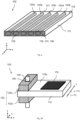
- FIG 2 shows a part of an example 102 for the first embodiment of the system according to the invention for temperature control of an electrode 111 in a perspective representation.
- the electrode 111 contains five heat pipes 120a to 120e and has an effective surface 115 and a side surface 116 .
- the side surface 116 also forms the coupling element 131 of the first embodiment 102.
- the temperature control device and other elements of the system according to the invention are in 2 not shown.
- the coupling element 131 is designed as a blackened heat transfer surface 136 .
- the second ends 122 of the heat pipes 120a to 120e all abut the side surface 116 of the electrode 111, while the first ends 121 of the heat pipes 120a to 120e are arranged close to the side surface of the electrode 111 opposite the side surface 116 but do not abut it.
- the heat-conducting tubes 120a to 120e are designed as straight tubes with an oval cross section and extend inside the electrode 111 parallel to the useful surface 115. Since they are not visible from the outside, their outlines are in figure 2 shown only as dashed lines.
- the heat-conducting tubes can also have other cross-sections, for example circular or flat.
- the heat-conducting tubes can also have irregular cross-sections or locally different cross-sections if, for example, they are slightly flattened or deformed during assembly in the electrode.
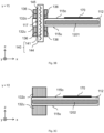
- FIG. 3A a schematic perspective view of the system 103
- FIG. 3B and 3C each a schematic cross-section through the system 103 Figure 3A at positions Y1 and Y2, respectively.
- the system 103 includes heat pipes 1201 and 1202, which are arranged in the electrode 112, and a coupling element 132, which is a separate body opposite the electrode 112 and is not directly connected to the heat pipes 1201 and 1202.
- the coupling element 132 consists of an upper part 132o, which adjoins the upper effective surface 115o of the electrode 112, and a lower part 132u, which adjoins the lower effective surface 115u of the electrode 112.
- a substrate 170 can be arranged and held on the upper usable surface 115o in an area in which the coupling element 132 is not arranged, as is shown in FIGS Figures 3A to 3C is shown.
- the lower usable area 115u is not used in the illustrated example of the system 103, but can contain, for example, a gas distributor for supplying a process gas into a process space, which is arranged below the lower usable area 115u along the z-direction.
- the coupling element 132 can also be arranged on only one of the surfaces of the electrode 112, ie, for example, consist only of the upper part 132o.
- the system 103 also contains a temperature control device 140, which is an infrared radiator 141 in the example shown, which is arranged in a cladding tube 144, for example made of quartz glass.
- An atmosphere different from a process atmosphere created during the treatment of the substrate 170 may be present in the cladding tube 144 .
- the atmosphere in the cladding tube 144 can be air at normal pressure (10 5 Pa), while the process atmosphere is a mixture of silane (SiH 4 ) and hydrogen (H 2 ) at a pressure of 100 Pa.
- This has the advantage that the infrared emitter 141 is shielded from the process atmosphere and can be operated under ideal environmental conditions.
- the infrared emitter 141 may be formed uniformly over its entire length (along the z-direction in the figures) or may have different areas along its length, with the different areas radiating different amounts of heat.
- the temperature control device 140 is arranged in an opening 145 in the coupling element 132 and in an opening 117 in the electrode 112 . Both openings 144 and 117 each extend through the entire coupling element 132 or the entire electrode 112, so that the temperature control device 140 protrudes both from the upper part 132o of the coupling element 132 and from the lower part 132u of the coupling element 132. However, the temperature control device 140 can, for example, also end inside the coupling element 132, for example inside the upper part 132o, so that the opening 145 of the coupling element 132 does not reach the surface of the upper part 132o.
- the cladding tube 144 has, for example, a circular cross section with a diameter of 32 mm.
- the cladding tube 144 is spaced apart from the coupling element 132 and the electrode 112 by a gap with a width of, for example, 0.5 mm to 5 mm to allow thermal expansion of the cladding tube 144, the coupling element 132 and the electrode 112.
- the inner surfaces of the opening 145 of the coupling element 132 which are outer surfaces of the coupling element 132, form the heat transfer surface of the coupling element 132 and can, for example, be designed as a blackened heat transfer surface 136 in order to absorb the thermal radiation particularly well. This means that the heat transfer surface 136 has an increased absorption capacity compared to the other areas of the coupling element 132 .
- the coupling element consists, for example, of aluminum, but can also consist of an electrically non-conductive material.
- the heat pipes 1201 and 1202 are arranged inside the electrode 112 with both ends of the heat pipes 1201 and 1202 being inside the electrode 112 .
- the heat pipe or heat pipes 1201 are arranged in a region of the electrode 112 along the y-direction in which the opening 117 in the electrode 112 is also formed, as is shown in FIG Figure 3B is shown.
- the heat pipes 1202 are arranged in areas of the electrode 112 along the y-direction where no opening 117 is formed in the electrode 112, as shown in FIG Figure 3C is shown.
- the heat pipe or heat pipes 1201 have a shorter length along the x-direction than the heat pipes 1202.
- the heat pipes 1201 and 1202 are completely spaced from the coupling element 132, i.e.
- the amount of heat is thus transferred from the temperature control device 140 to the heat pipes 1201 and 1202 or vice versa via the material of the electrode 112 , the temperature control device 140 heating the electrode 112 both directly and indirectly via the coupling element 132 .
- the heat transfer from coupling element 132 to electrode 112 is significantly greater than the heat transfer from temperature control device 140 directly to the electrode due to the larger coupling surface (interface between coupling element 132 and electrode 112) and the better thermal conductivity of coupling element 132 compared to electrode 112 112.
- the coupling element 132 extends overall over a significantly greater length along the temperature control device 140 (in the z-direction) than the electrode 112.
- the coupling area between the coupling element 132 and the electrode 112 in an xy plane is 100 cm 2 , for example, which corresponds to less than 15% of the effective area of the electrode 112 , for example.
- more than one temperature control device 140 can be arranged in openings 145 and 117, for example two or three temperature control devices, with these also different amounts of heat can be transferred to the coupling element 132 .
- the temperature control device 140 it is also possible for the temperature control device 140 to be a resistive heater or a fluid-based device, with appropriate electrical insulation being provided between the electrode 112 and the temperature control device 140 and possibly also between the coupling element 132 and the temperature control device 140 .
- the coupling element 132 can also have other elements, such as a gas supply or an electrical connection for supplying a potential to the electrode 112 .
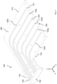
- FIG 4 shows part of a first example 104 for the third embodiment of the system according to the invention for temperature control of an electrode 113, the temperature control device not being shown.
- the third embodiment of the system according to the invention is also characterized in that a coupling element is designed as an independent body.
- the coupling element 133 borders on a side surface 116 of the electrode 113 .
- 4 shows only an underside of the electrode 113 and the coupling element 133, in which heat-conducting tubes 120f to 120k are arranged.
- the first end 121 and the second end 122 are designated as an example for the heat pipe 120k.
- All heat-conducting tubes 120f to 120k are designed as bent tubes with a circular cross-section, which first extend along the x-direction from the coupling element 133 in the electrode 113 and then continue along the y-direction. Due to this bend, the heat pipes 120f to 120k can evenly temper the electrode 113 over its entire extent along the xy plane, while at the same time the coupling element 133 has a significantly smaller extent in relation to the y direction than the electrode 113.
- the coupling element 133 has a heat transfer surface 135, for example.
- the heat transfer surface 135 has a greater extent along the z-direction.
- the heat-conducting tubes 120f to 120k are arranged in recesses provided for this purpose in the electrode 113 or in the coupling element 133.
- the depressions are preferably dimensioned such that the heat-conducting tubes 120f to 120k are accommodated almost completely in the underside of the electrode 113 or the underside of the coupling element 133 .
- the depressions for the heat pipes 120f to 120k are slightly less deep than the height of the heat pipes, so that the Heat pipes are slightly compressed when the tops of the electrode 113 or the coupling element 133 are mounted on the undersides of the electrode 113 or the coupling element 133 .
- Very good thermal contact can thus be achieved between the thermally conductive tubes 120f to 120k and the electrode 113 or the coupling element 133 without additional aids such as soldering or thermally conductive pastes.
- the heat-conducting tubes 120f to 120k it is also possible for the heat-conducting tubes 120f to 120k to be accommodated by the underside of the electrode 113 or the underside of the coupling element 133 up to approximately half of their extension along the z-direction.
- the tops of the electrode 113 or the coupling element 133 then each also have corresponding indentations, so that the heat pipes 120f to 120k can be completely covered by the material of the electrode 113 or of the coupling element 133 are surrounded.
- the electrode 113 and the coupling element 133 have fastening holes 180, which can be through holes or holes ending in the material of the electrode 113 or the coupling element 133 and into which fastening means, For example, screws, rivets or the like can be introduced.
- a support opening 190 e.g substrate is used.
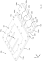
- FIGS. 5A and 5B are perspective views of part of a second example 105 for the third embodiment of the system according to the invention, wherein Figure 5B only the lower part of the in Figure 5A components shown.
- the temperature control device and possibly other components of the system according to the invention are not shown.
- the electrode 114 and the coupling element 134 in turn each consist of an upper part 114o or 134o and a lower part 114u or 134u, which each have depressions in which heat-conducting tubes 120l to 120q are arranged.
- the heat pipes 120l to 120q extend straight along the x-direction and have no bends.
- the coupling element 134 extends over the entire extent of the side surface 116 of the electrode 114 along the y-direction, so that the coupling element 134 and the electrode 114 have the same extent along the y-direction, and is spaced apart from the side surface 116 .
- the heat pipes 120l to 120q are uniform over the extent of the electrode 114 and of the coupling element 134 distributed along the y-direction. However, other distributions can also be advantageous in order to compensate for any large heat emissions from the electrode 114 on its side surfaces or to achieve other specific heat distributions over the extent of the electrode 114 .
- the coupling element 134 again has a heat transfer surface 135 which is larger in the z-direction than the side surface 116 of the electrode 114 .
- Figure 5A shows the electrode 114 and the coupling element 134 in a deployed state, with the upper and lower parts 114o and 114u or 134o and 134u being fastened to one another by means of fastening means 181 (e.g. screws) which are screwed into fastening holes 180 (shown in Figure 5B ) are introduced, are firmly but detachably connected.
- fastening means 181 e.g. screws
- fastening holes 180 shown in Figure 5B
- the Figure 5B only the lower part 114u of the electrode 114 with the lower part 116u of the side surface 116 and the lower part 134u of the coupling element 134 with the lower part 135u of the heat transfer surface 135.
- a depression 118 for receiving a substrate holder or a substrate is formed in the effective surface 115 of the electrode 114 .
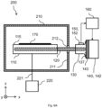
- FIG 6A shows a schematic representation of a first example 200 of the treatment plant according to the invention.
- the treatment system 200 has a treatment chamber 210 in which at least one electrode 110 is arranged.
- the electrode 110 is heated or cooled by means of a temperature control system according to the invention.
- the system for temperature control has at least one heat pipe 120, a coupling element 130 and a temperature control device 140, as is the case with reference to FIG Figure 1B was described.
- a temperature measuring unit 150 and a control unit 160 are also provided.
- the coupling element 130 and the temperature control device 140 are arranged outside the treatment chamber 210 in the first example 200 .
- a wall 211 of the treatment chamber 210 which delimits the interior of the treatment chamber 210 from its surroundings, has a passage 212 for the heat-conducting tube 120, which thermally insulates the heat-conducting tube 120 from the wall 211 and, if appropriate, also electrically insulates the heat-conducting tube 120 from the wall 211 guaranteed.
- a substrate 170 which does not belong to the treatment system 200 , is arranged on the effective surface 115 of the electrode 110 and can be treated by means of a process carried out in the treatment chamber 210 .
- a defined electrode voltage can be applied to the electrode 110 by an electrical voltage supply 220 via an electrical supply line 221 .
- the voltage can also be transmitted without contact.
- Other elements of the treatment system 200 such as vacuum pumps and gas supply lines, are not shown here.
- the first example 200 shown enables the use of a temperature control device 140 which achieves heat input into the coupling element 130 by thermal conduction, for example the resistive heater 142 (as shown) or a fluid-based temperature control device.
- a temperature control device 140 which achieves heat input into the coupling element 130 by thermal conduction
- the resistive heater 142 as shown
- a fluid-based temperature control device In this case, the effects of a leak in the fluid-based temperature control device can be reduced by relocating the temperature control device out of the treatment chamber 210 .
- a radiation source as a temperature control device.
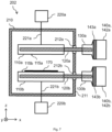
- FIG. 6B shows a schematic representation of a second example 201 of the treatment plant according to the invention.
- treatment system 201 has the same components as treatment system 200, namely an electrode 110, a heat pipe 120, a coupling element 130, a temperature control device 140, a temperature measuring unit 150, a control unit 160, a treatment chamber 210 with a wall 211, and an electrical power supply 220 and an electrical supply line 221.
- the coupling element 130 is now arranged within the treatment chamber 210, while the temperature control device 140 is still arranged outside of the treatment chamber 210.
- This is particularly suitable for the use of an infrared radiator 141 (as shown) or an inductive device as a temperature control device 140, as is the case with reference to FIG the Figure 1A is described.
- a radiation window 213 for example made of quartz glass, is arranged in the wall 211 of the treatment chamber 210 in the radiation path between the temperature control device 140 and the coupling element 130 .
- FIG. 7 12 schematically represents a third example 202 of the treatment plant according to the invention, in which several electrodes are arranged in the treatment chamber.
- two electrodes 110a and 110b are arranged in the treatment chamber 210, with the effective surfaces 115a and 115b of the electrodes 110a and 110b being arranged parallel to one another and opposite one another.
- the two electrodes 110a and 110b thus form a plate capacitor which, when an appropriate potential is applied, makes it possible, for example, to ignite a plasma between the electrodes 110a and 110b.
- the electrodes 110a and 110b are each connected to a separate electrical voltage supply 220a or 220b via separate electrical supply lines 221a or 221b.
- both electrodes 110a and 110b can also have different potentials applied to them by only one electrical voltage supply.
- only one electrode for example the electrode 110b
- the other electrode for example the electrode 110a
- both electrodes can also hold one or more substrates, or one or both electrodes can perform other functions, such as the function of a gas supply.
- Each electrode 110a and 110b is heated or cooled via a separate system for tempering the respective electrode.
- a first heat pipe 120a transfers a first quantity of heat between a first coupling element 130a and the first electrode 110a, the first coupling element 130a being connected to the first coupling element by a first temperature control device 140a, e.g. a first resistive heater 142a, via a first electrical insulator 143a 130a, is heated to a first temperature.
- a second heat pipe 120b transfers a second amount of heat between a second coupling element 130b and the second electrode 110b, the second coupling element 130b being connected to the second coupling element 130b by a second temperature control device 140b, e.g.
- a second resistive heater 142b via a second electrical insulator 143b is connected, is heated to a second temperature.
- Different or the same first or second temperatures of the coupling elements 130a and 130b and thus also of the electrodes 110a and 110b can thus be set.
- several heat-conducting tubes can also be used to transfer the heat between the respective coupling element and the respective electrode.
- the number of heat pipes, their design and/or arrangement can be the same or different for the different systems for temperature control of an electrode.
- the coupling elements 130a and 130b and the temperature control devices 140a and 140b are arranged, for example, outside of the treatment chamber 210, as is the case with reference to FIG Figure 6A was explained.
- the treatment chamber 210 therefore also has two passages 212a and 212b for the heat-conducting tubes 120a and 120b, respectively.
- Identical temperature control devices 140a and 140b are shown as examples, but different temperature control devices can also be used for each of the electrodes present, or a common temperature control device can be used for a plurality of electrodes.
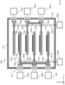
- FIG 8 schematically shows a fourth example 203 of the treatment system according to the invention.
- an electrode stack consisting of a plurality of electrodes 110a to 110f arranged one above the other is arranged in the treatment chamber 210, the effective surfaces of the respective electrodes 110a to 110f being parallel to one another in different xy planes, which run along the z-direction are arranged, run.
- the outer electrodes 110a and 110f of the electrode stack each have only one usable surface, which faces the adjacent electrode, ie the electrode 110b or the electrode 110e.
- the inner electrodes 110b to 110e each have two opposing usable surfaces, which each face a usable surface of an adjacent electrode.
- An example of the electrode 110b is an upper usable surface 115o and a lower usable surface 115u in 8 characterized in that the upper effective surface 115o faces the effective surface of the electrode 110a, while the lower effective surface 115u faces the upper effective surface of the electrode 110c.
- the number of electrodes in the electrode stack can be freely selected and is not limited to the number of six electrodes shown.
- electrode stacks of 20, 50 or even 100 electrodes arranged one above the other are known, it also being possible for a plurality of electrode stacks to be arranged laterally next to one another.
- Each electrode 110a to 110f is heated or cooled to a specific temperature via a separate system for tempering the respective electrode.
- each of the electrodes 110a to 110f is connected to a coupling element 130a to 130f via at least one heat pipe 120, designated for the electrode 110b by way of example.
- all coupling elements 130a to 130f are arranged within the treatment chamber 210 and are each heated by temperature control devices 140a to 140f designed as infrared radiators.
- radiation windows 213 are in each radiation path between a temperature control device 140a to 140f and the coupling element 130a to 130f associated with it in the wall 211 of the Treatment chamber 210 arranged as with reference to FIG Figure 6B was explained.
- one or more of the temperature control devices 140a to 140f can also be replaced by a common temperature control device if the same temperatures are to be achieved at the respective associated coupling elements.
- additional heat-conducting tubes that connect various coupling elements to one another can also be used. Examples are in 8 two additional heat pipes 230a and 230b are shown. In this case, the heat pipe 230a connects the coupling elements 130b, 130d and 130f to one another, while the heat pipe 230b connects the coupling elements 130c and 130e to one another.
- the coupling element 130a is not connected to other coupling elements by the heat pipe 230b, since, for example, the electrode 110a is to be tempered to a different temperature than the electrodes 110c and 110e.
- the electrode temperature can also be connected to the coupling elements 130c and 130e via the heat pipe 230b if the electrode temperature is correspondingly desired.
- the use of two different additional heat-conducting tubes 230a and 230b is justified by the potential supply to the electrodes via the respective coupling elements and heat-conducting tubes and their spatial arrangement.
- the arrangement of additional heat-conducting tubes can be designed differently in other configurations of the potential supply and the systems for temperature control of the electrodes.
- Two adjacent electrodes each form a plate capacitor, it being possible for adjacent electrodes to have different electrical potentials applied to them.
- the potential is applied by supplying electrical voltage to the coupling elements 130a to 130f, with the coupling elements 130a to 130f and the heat-conducting tubes 120 being designed to be electrically conductive.
- a first potential is applied to the electrodes 110b, 110d and 110f via the respective coupling elements 130b, 130d and 130f and the respective heat-conducting tubes 120 from an electrical voltage supply 220a via an electrical supply line 221a.
- the electrodes 110a, 110c and 110e are acted upon by a second potential via the respective coupling elements 130a, 130c and 130c and the respective heat-conducting tubes 120 from an electrical voltage supply 220b via an electrical supply line 221b, the second potential being different from the first potential.
- a second potential via the respective coupling elements 130a, 130c and 130c and the respective heat-conducting tubes 120 from an electrical voltage supply 220b via an electrical supply line 221b, the second potential being different from the first potential.
- the coupling elements 130a to 130f of electrodes to which a different potential is applied are arranged offset in relation to one another.
- all coupling elements 130a, 130c and 130e that are acted upon in the same way are arranged on the right side of the electrode stack and all coupling elements 130b, 130d and 130f that are acted upon with a different potential are arranged on the left side of the electrode stack.
- the coupling elements, which are assigned to electrodes that are subjected to different loads are each arranged offset with respect to one another along the x-direction.
- the coupling elements of all systems for temperature control of an electrode can be arranged on one side of the electrode stack, ie on one side along the x-direction, with the coupling elements assigned to differently charged electrodes then preferably along the y-direction are staggered.
- the arrangement of all the coupling elements on one side of the electrode stack has the advantage that all the coupling elements can optionally be heated or cooled by a temperature control device.
- the coupling elements connected thereto and the associated electrodes can also have a potential applied to them via the additional heat-conducting tube.
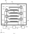
- FIG 9 shows a schematic representation of a fifth example 204 of the treatment plant according to the invention, in which - similar to the fourth example 203 figure 8 - Adjacent coupling elements 133 are arranged offset in a stack of electrodes 110 arranged one above the other and the coupling elements 133, which have the same electrical potential, are temperature-controlled via a common temperature-control device 140a or 140b.
- a common temperature-control device 140a or 140b This comes with reference to the Figures 3A to 3C described system for temperature control of the electrodes used.
- Each electrode 110a to 110f has heat-conducting tubes 120 in its interior, the second end of which extends into a volume region of the respective electrode 110, of which at least one of the outer surfaces is adjacent to the respective coupling element 133a to 133f.
- the coupling elements 133 of adjacent electrodes 110 which have a different electrical potential, are arranged on opposite sides of the electrodes 110 with respect to the x-direction.
- the electrical potential is applied to the electrodes 110a to 110f via the coupling elements 133a to 133f, which are each connected to a voltage supply 220a or a voltage supply 220b electrical leads 221a and 221b are connected, respectively.
- the coupling elements 133b, 133d and 133f which are at a first potential, are connected via the first temperature control device 140a, which extends along the z-direction, the first temperature control device 140a being connected through openings (bores) in the respective coupling elements 133b, 133d and 133f and is guided in the respective electrodes 110b, 110d and 110f, and are temperature-controlled by the first temperature-control device 140a.
- the coupling elements 133a, 133c and 133e which are at a second potential and through which the second temperature control device 140b runs, are temperature controlled by the second temperature control device 140b.
- the second temperature control device 140b also runs through corresponding openings in the electrodes 110a, 110c and 110e.
- the coupling elements 133 can each extend along the z-direction until close to the closest coupling elements 133, which are connected to the same temperature control device 140a or 140b, so that almost the entire temperature control device 140a or 140b is within the respective coupling elements 133 or electrodes 110 runs.
- the coupling elements 133 preferably do not directly adjoin one another in order to be able to compensate for thermal expansion of the coupling elements 133 at elevated temperatures.
- larger areas of the temperature control devices 140a or 140b can also be located outside of the coupling elements 133 and the electrodes 110, as is shown in 9 is indicated.
- infrared radiators that emit a large amount of heat only in certain areas of their extension can be used, with these areas then being surrounded by the coupling elements 133 and electrodes 110, while areas of the infrared radiator that generate only little infrared radiation are outside of the coupling elements 133 and the electrodes 110 are arranged.
- the temperature control devices 140a and 140b pass through the wall 211 of the treatment chamber 210 and are connected to a control unit 160 outside of the treatment chamber 210 .
- This exemplary embodiment has the advantages of a very small space requirement within the treatment chamber 210, an air atmosphere for the infrared emitters sealed off by the cladding tube, as has already been explained with reference to FIG Figures 3A to 3C explained, and only a very few necessary vacuum feedthroughs through the wall 211 of the treatment chamber 210.
- the coupling elements 133 can also be used to supply a process gas to gas distributors which are arranged, for example, on the lower effective surfaces 115u of the electrodes 110a to 110e. This is not shown here for reasons of clarity.
- Some or all of the options mentioned for designing the system according to the invention for temperature control of an electrode and the treatment system according to the invention can also be combined with one another, as long as they are not mutually exclusive.
- different temperature control devices and different numbers, configurations and/or arrangements of heat pipes and coupling elements can be used in different systems for temperature control of an electrode.
- the number of electrodes in a treatment system and the number, configuration and/or arrangement of the coupling elements and of additional heat-conducting tubes is not limited to the examples shown.
- the specified values for distances and sizes are guide values, which can, however, be exceeded or undershot if the corresponding components are selected appropriately.
Landscapes
- Physics & Mathematics (AREA)
- Engineering & Computer Science (AREA)
- Plasma & Fusion (AREA)
- Chemical & Material Sciences (AREA)
- Analytical Chemistry (AREA)
- Resistance Heating (AREA)
- Physical Or Chemical Processes And Apparatus (AREA)
- Heat Treatment Of Articles (AREA)
- Drying Of Semiconductors (AREA)
- Container, Conveyance, Adherence, Positioning, Of Wafer (AREA)
Claims (15)
- Système (100-105) de régulation de température d'une électrode (110-114 ; 110a-110f), présentant au moins un tube thermoconducteur (120 ; 120a-120q ; 1201, 1202), un élément de couplage (130-134 ; 130a-130f) et un dispositif de régulation de température (140 ; 140a-140f), le tube thermoconducteur (120 ; 120a-120q ; 1201, 1202) étant agençable au moins partiellement et avec au moins une première extrémité dans l'électrode (110-114 ; 110a-110f), l'élément de couplage (130-134 ; 130a-130f) étant conçu pour chauffer ou pour refroidir une seconde extrémité du tube thermoconducteur (120 ; 120a-120q ; 1201, 1202) et le dispositif de régulation de température (140 ; 140a-140f) étant conçu pour chauffer ou pour refroidir l'élément de couplage (130-134 ; 130a-130f), l'électrode (110-114 ; 110a-110f) et le dispositif de régulation de température (140 ; 140a-140f) étant isolés électriquement l'un de l'autre.
- Système selon la revendication 1, caractérisé en ce que l'élément de couplage (130-134 ; 130a-130f) constitue au moins une partie d'une surface externe de l'électrode (110-114 ; 110a-110f), à laquelle la seconde extrémité du tube thermoconducteur (120 ; 120a-120q ; 1201, 1202) est adjacente, et laquelle présente un degré d'absorption thermique accru par rapport à d'autres zones de l'électrode (110-114 ; 110a-110f).
- Système selon la revendication 1, caractérisé en ce que l'élément de couplage (130-134 ; 130a-130f) est un corps isolé de l'électrode (110-114 ; 110a-110f) en un matériau comportant une conductivité thermique élevée et peut être agencé dans une zone de la surface externe de l'électrode (110-114 ; 110a-110f) qui est adjacente à une zone de volume de l'électrode (110-114 ; 110a-110f) dans laquelle au moins la seconde extrémité du tube thermoconducteur (120 ; 120a-120q ; 1201, 1202) peut être agencée.
- Système selon la revendication 1, caractérisé en ce que l'élément de couplage (130-134 ; 130a-130f) est un corps isolé de l'électrode (110-114 ; 110a-110f) en un matériau comportant une conductivité thermique élevée, dans lequel au moins la seconde extrémité du tube thermoconducteur (120 ; 120a-120q ; 1201, 1202) est agencée.
- Système selon la revendication 3 ou 4, caractérisé en ce que l'élément de couplage (130-134 ; 130a-130f) est constitué d'un matériau électriquement conducteur.
- Système selon la revendication 3 ou 4, caractérisé en ce que l'élément de couplage (130-134 ; 130a-130f) est constitué d'un matériau électriquement isolant.
- Système selon l'une des revendications 3 à 6, caractérisé en ce que l'élément de couplage (130-134 ; 130a-130f) présente une surface de transfert de chaleur (135) qui présente un degré d'absorption thermique accru ou une conductivité thermique accrue par rapport à d'autres zones de l'élément de couplage (130-134 ; 130a-130f).
- Système selon l'une des revendications précédentes, caractérisé en ce que le dispositif de régulation de température (140 ; 140a-140f) est un émetteur infrarouge (141), un inducteur, un appareil de chauffage résistif (142) ou un dispositif à base de fluide.
- Système selon l'une des revendications précédentes, caractérisé en ce que le système contient en outre une unité de mesure de température (150) et une unité de commande (160), dans lequel l'unité de mesure de température (150) est conçue pour déterminer un paramètre associé à la température de l'élément de couplage (130-134 ; 130a-130f) et l'unité de commande (160) est conçue pour commander le dispositif de régulation de température (140 ; 140a-140f).
- Installation de traitement (200-204) comportant une chambre de traitement (210) et au moins une électrode (110-114 ; 110a-110f) à l'intérieur de la chambre de traitement (210), caractérisée en ce que l'installation de traitement présente en outre au moins un système (100-105) pour la régulation de température d'une électrode selon l'une des revendications précédentes.
- Installation de traitement (200-204) selon la revendication 10, caractérisée en ce que le dispositif de régulation de température (140 ; 140a-140f) d'au moins un premier système (100-105) pour la régulation de température d'une électrode est agencé à l'extérieur de la chambre de traitement (210).
- Installation de traitement (200-204) selon la revendication 11, caractérisée en ce que l'élément de couplage (130-134 ; 130a-130f) du premier système (100-105) pour la régulation de température d'une électrode est agencé entièrement à l'intérieur de la chambre de traitement (210) et le dispositif de régulation de température (140 ; 140a-140f) du premier système (100-105) pour la régulation de température d'une électrode est un émetteur infrarouge (141) ou un inducteur.
- Installation de traitement (200-204) selon l'une des revendications 10 à 12, caractérisée en ce que l'installation de traitement présente plusieurs électrodes (110-114 ; 110a-110f) et plusieurs systèmes (100-105) pour la régulation de température d'une électrode, les éléments de couplage (130-134 ; 130a-130f) d'au moins deux systèmes (100-105) pour la régulation de température d'une électrode étant reliés l'un à l'autre par l'intermédiaire d'au moins un tube thermoconducteur (230a, 230b) supplémentaire.
- Installation de traitement (200-204) selon l'une des revendications 10 à 13, caractérisée en ce que- l'installation de traitement présente plusieurs électrodes (110-114 ; 110a-110f) à l'intérieur de la chambre de traitement, dont les surfaces utiles sont respectivement parallèles les unes aux autres et sont agencées en regard les unes des autres, et des électrodes (110-114 ; 110a-110f) voisines étant reliées à une ou plusieurs alimentations en tension (220 ; 220a ; 220b) de manière à pouvoir être sollicitées par des tensions d'électrode différentes,- les systèmes (100-105) pour la régulation de température d'une électrode sont respectivement des systèmes selon la revendication 3 ou 4, dans lesquels l'élément de couplage (130-134 ; 130a-130f) présente sur au moins l'une de ses surfaces externes le même potentiel que l'électrode (110-114 ; 110a-110f) associée, et- les éléments de couplage (130-134 ; 130a-130f) de systèmes pour la régulation de température d'une électrode (110-114 ; 110a-110f) qui sont associés à des électrodes (110-114 ; 110a- 110f) voisines sont agencés de manière décalée les uns par rapport aux autres dans au moins une direction perpendiculairement à l'espacement des électrodes (110-114 ; 110a-110f) voisines.
- Installation de traitement (200-204) selon l'une des revendications 10 à 14, caractérisée en ce que l'élément de couplage (130-134 ; 130a-130f) d'au moins un système (100-105) pour la régulation de température d'une électrode est relié à une alimentation en tension (220 ; 220a ; 220b) et est conçu, seul ou conjointement avec l'au moins un tube thermoconducteur (120 ; 120a-120q ; 1201, 1202) respectif, pour solliciter l'électrode (110-114 ; 110a-110f) associée avec une tension d'électrode.
Applications Claiming Priority (2)
| Application Number | Priority Date | Filing Date | Title |
|---|---|---|---|
| DE102017223592.6A DE102017223592B4 (de) | 2017-12-21 | 2017-12-21 | System zur elektrisch entkoppelten, homogenen Temperierung einer Elektrode mittels Wärmeleitrohren sowie Bearbeitungsanlage mit einem solchen System |
| PCT/EP2018/085820 WO2019121899A1 (fr) | 2017-12-21 | 2018-12-19 | Système d'équilibrage de température homogène électriquement découplé d'une électrode au moyen de tubes thermoconducteurs ainsi qu'équipement de traitement avec un tel système |
Publications (3)
| Publication Number | Publication Date |
|---|---|
| EP3729486A1 EP3729486A1 (fr) | 2020-10-28 |
| EP3729486B1 true EP3729486B1 (fr) | 2023-08-30 |
| EP3729486C0 EP3729486C0 (fr) | 2023-08-30 |
Family
ID=64902075
Family Applications (1)
| Application Number | Title | Priority Date | Filing Date |
|---|---|---|---|
| EP18829350.0A Active EP3729486B1 (fr) | 2017-12-21 | 2018-12-19 | Système de contrôle thermique homogène électriquement découplé d'une électrode au moyen de tubes thermoconducteurs et installation de traitement comprenant ledit système |
Country Status (10)
| Country | Link |
|---|---|
| US (1) | US12198907B2 (fr) |
| EP (1) | EP3729486B1 (fr) |
| JP (1) | JP7274487B2 (fr) |
| KR (1) | KR102789061B1 (fr) |
| CN (2) | CN209119039U (fr) |
| DE (1) | DE102017223592B4 (fr) |
| EA (1) | EA202000177A1 (fr) |
| ES (1) | ES2960584T3 (fr) |
| SG (1) | SG11202005224TA (fr) |
| WO (1) | WO2019121899A1 (fr) |
Families Citing this family (2)
| Publication number | Priority date | Publication date | Assignee | Title |
|---|---|---|---|---|
| DE102017223592B4 (de) * | 2017-12-21 | 2023-11-09 | Meyer Burger (Germany) Gmbh | System zur elektrisch entkoppelten, homogenen Temperierung einer Elektrode mittels Wärmeleitrohren sowie Bearbeitungsanlage mit einem solchen System |
| DE102020124022A1 (de) | 2020-09-15 | 2022-03-17 | centrotherm international AG | Werkstückträger, System und Betriebsverfahren für PECVD |
Citations (1)
| Publication number | Priority date | Publication date | Assignee | Title |
|---|---|---|---|---|
| DE202010004109U1 (de) * | 2010-03-11 | 2011-10-21 | Asia Vital Components Co., Ltd. | Brückenverbindung von Wärmeleitrohren und deren Kühlmodul |
Family Cites Families (35)
| Publication number | Priority date | Publication date | Assignee | Title |
|---|---|---|---|---|
| GB2033704B (en) * | 1978-10-30 | 1982-09-29 | Electricity Council | Electron discharge heating device |
| US4381965A (en) * | 1982-01-06 | 1983-05-03 | Drytek, Inc. | Multi-planar electrode plasma etching |
| JPS6225411A (ja) | 1985-07-25 | 1987-02-03 | Fujitsu Ltd | プラズマcvd膜形成法 |
| US5231291A (en) * | 1989-08-01 | 1993-07-27 | Canon Kabushiki Kaisha | Wafer table and exposure apparatus with the same |
| JP3100236B2 (ja) * | 1992-08-03 | 2000-10-16 | 東京エレクトロン株式会社 | プラズマ処理装置 |
| US5647911A (en) | 1993-12-14 | 1997-07-15 | Sony Corporation | Gas diffuser plate assembly and RF electrode |
| DE4446297A1 (de) | 1994-12-23 | 1996-06-27 | Balzers Hochvakuum | Heizanordnung, Vakuumprozeßkammer mit einer solchen und Betrieb einer derartigen Vakuumprozeßkammer |
| JPH08203692A (ja) | 1995-01-25 | 1996-08-09 | Hitachi Ltd | 誘導結合プラズマ発生装置 |
| JP3393742B2 (ja) | 1995-09-28 | 2003-04-07 | 京セラ株式会社 | ウエハ保持部材 |
| JP4015210B2 (ja) | 1996-05-30 | 2007-11-28 | 富士電機システムズ株式会社 | オゾン発生装置 |
| US6566667B1 (en) | 1997-05-12 | 2003-05-20 | Cymer, Inc. | Plasma focus light source with improved pulse power system |
| KR100425445B1 (ko) | 2001-04-24 | 2004-03-30 | 삼성전자주식회사 | 플라즈마 에칭 챔버 및 이를 이용한 포토마스크 제조 방법 |
| JP2003100835A (ja) | 2001-09-25 | 2003-04-04 | Hitachi Kokusai Electric Inc | 基板処理装置 |
| JP4186644B2 (ja) | 2003-02-17 | 2008-11-26 | 株式会社Ihi | 真空処理装置の冷却装置 |
| KR100528334B1 (ko) * | 2003-04-08 | 2005-11-16 | 삼성전자주식회사 | 베이크 시스템 |
| JP4463583B2 (ja) | 2004-02-13 | 2010-05-19 | 東京エレクトロン株式会社 | 成膜方法および成膜装置 |
| US7548303B2 (en) * | 2004-09-04 | 2009-06-16 | Nikon Corporation | Cooling assembly for a stage |
| CN2789934Y (zh) | 2005-03-09 | 2006-06-21 | 南开大学 | 大面积太阳电池纳米透明导电膜制备专用加热装置 |
| ATE514183T1 (de) * | 2006-11-17 | 2011-07-15 | Centrotherm Thermal Solutions Gmbh & Co Kg | Verfahren und anordnung zum thermischen behandeln von substraten |
| WO2009042137A2 (fr) | 2007-09-25 | 2009-04-02 | Lam Research Corporation | Modules de régulation de température pour ensembles d'électrodes en pomme de douche pour appareils de traitement au plasma |
| JP2009170721A (ja) | 2008-01-17 | 2009-07-30 | Nikon Corp | 静電チャック、マスク保持装置、基板保持装置、露光装置及びデバイスの製造方法 |
| WO2010050169A1 (fr) | 2008-10-29 | 2010-05-06 | 積水化学工業株式会社 | Dispositif de traitement au plasma |
| SG173052A1 (en) | 2009-03-03 | 2011-08-29 | Soitec Silicon On Insulator | Gas injectors for cvd systems with the same |
| JP5320171B2 (ja) * | 2009-06-05 | 2013-10-23 | 東京エレクトロン株式会社 | 基板処理装置 |
| CN102482775A (zh) | 2009-09-25 | 2012-05-30 | 京瓷株式会社 | 沉积膜形成装置及沉积膜形成方法 |
| JP4852653B2 (ja) | 2010-03-15 | 2012-01-11 | シャープ株式会社 | プラズマ処理装置、プラズマ処理方法および半導体素子の製造方法 |
| WO2012042664A1 (fr) * | 2010-10-01 | 2012-04-05 | 東芝三菱電機産業システム株式会社 | Appareil de trempage |
| US10274270B2 (en) | 2011-10-27 | 2019-04-30 | Applied Materials, Inc. | Dual zone common catch heat exchanger/chiller |
| US8975817B2 (en) | 2012-10-17 | 2015-03-10 | Lam Research Corporation | Pressure controlled heat pipe temperature control plate |
| US20140356985A1 (en) * | 2013-06-03 | 2014-12-04 | Lam Research Corporation | Temperature controlled substrate support assembly |
| KR101905158B1 (ko) * | 2013-08-06 | 2018-10-08 | 어플라이드 머티어리얼스, 인코포레이티드 | 국부적으로 가열되는 다-구역 기판 지지부 |
| DE102015113962A1 (de) * | 2015-08-24 | 2017-03-02 | Meyer Burger (Germany) Ag | Substratbehandlungsvorrichtung |
| DE102016215712A1 (de) | 2016-08-22 | 2018-02-22 | Siemens Aktiengesellschaft | Vorrichtung und Verfahren zur Erzeugung eines elektrischen Plasmas |
| EP3302006A1 (fr) * | 2016-09-30 | 2018-04-04 | AT & S Austria Technologie & Systemtechnik Aktiengesellschaft | Support de composant comprenant au moins un caloduc et procédé de production dudit support de composant |
| DE102017223592B4 (de) * | 2017-12-21 | 2023-11-09 | Meyer Burger (Germany) Gmbh | System zur elektrisch entkoppelten, homogenen Temperierung einer Elektrode mittels Wärmeleitrohren sowie Bearbeitungsanlage mit einem solchen System |
-
2017
- 2017-12-21 DE DE102017223592.6A patent/DE102017223592B4/de active Active
-
2018
- 2018-12-19 SG SG11202005224TA patent/SG11202005224TA/en unknown
- 2018-12-19 JP JP2020534418A patent/JP7274487B2/ja active Active
- 2018-12-19 US US16/956,387 patent/US12198907B2/en active Active
- 2018-12-19 KR KR1020207020772A patent/KR102789061B1/ko active Active
- 2018-12-19 EP EP18829350.0A patent/EP3729486B1/fr active Active
- 2018-12-19 WO PCT/EP2018/085820 patent/WO2019121899A1/fr not_active Ceased
- 2018-12-19 ES ES18829350T patent/ES2960584T3/es active Active
- 2018-12-19 EA EA202000177A patent/EA202000177A1/ru unknown
- 2018-12-21 CN CN201822167758.0U patent/CN209119039U/zh active Active
- 2018-12-21 CN CN201811569221.5A patent/CN109950120B/zh active Active
Patent Citations (1)
| Publication number | Priority date | Publication date | Assignee | Title |
|---|---|---|---|---|
| DE202010004109U1 (de) * | 2010-03-11 | 2011-10-21 | Asia Vital Components Co., Ltd. | Brückenverbindung von Wärmeleitrohren und deren Kühlmodul |
Also Published As
| Publication number | Publication date |
|---|---|
| CN109950120A (zh) | 2019-06-28 |
| SG11202005224TA (en) | 2020-07-29 |
| WO2019121899A1 (fr) | 2019-06-27 |
| JP7274487B2 (ja) | 2023-05-16 |
| US12198907B2 (en) | 2025-01-14 |
| KR20200100749A (ko) | 2020-08-26 |
| DE102017223592A1 (de) | 2019-06-27 |
| CN209119039U (zh) | 2019-07-16 |
| EP3729486A1 (fr) | 2020-10-28 |
| US20210090863A1 (en) | 2021-03-25 |
| ES2960584T3 (es) | 2024-03-05 |
| CN109950120B (zh) | 2022-11-29 |
| JP2021507536A (ja) | 2021-02-22 |
| EP3729486C0 (fr) | 2023-08-30 |
| DE102017223592B4 (de) | 2023-11-09 |
| KR102789061B1 (ko) | 2025-03-28 |
| EA202000177A1 (ru) | 2020-09-28 |
Similar Documents
| Publication | Publication Date | Title |
|---|---|---|
| DE4121534C2 (de) | Kühlvorrichtung | |
| WO2013186106A1 (fr) | Dispositif de chauffage électrique pour un véhicule a moteur | |
| DE2825582A1 (de) | Waermeabfuehreinrichtung fuer halbleitermodul | |
| EP3729486B1 (fr) | Système de contrôle thermique homogène électriquement découplé d'une électrode au moyen de tubes thermoconducteurs et installation de traitement comprenant ledit système | |
| EP2486357B1 (fr) | Dispositif de refroidissement pour un capteur apte à être utilisé à une température ambiante élevée | |
| EP2106892A1 (fr) | Plaque chauffante pour pièces à fabriquer | |
| EP1319240B1 (fr) | Source et dispositif de rayonnement | |
| DE102007032496B3 (de) | Vorrichtung zur Erzeugung eines Plasma-Jets | |
| EP3341961B1 (fr) | Dispositif de traitement de substrat | |
| DE102014208433A1 (de) | Thermoelektrische Vorrichtung, insbesondere für ein Kraftfahrzeug | |
| DE10163087B4 (de) | Infrarotstrahler zur thermischen Behandlung von Gütern | |
| DE102007044634B4 (de) | Hochtemperatur-Polymer-Elektrolyt-Membran-Brennstoffzelle (HT-PEMFC) einschließlich Vorrichtungen zu deren Kühlung | |
| DE102019207808A1 (de) | Kälteplatte für Elektronik | |
| EP4010650B1 (fr) | Échangeur de chaleur à air et son procédé de production, et ensemble électronique équipé de ce dernier | |
| EP1889663A1 (fr) | Dispositif pour chauffer un échantillon | |
| DE102009047751B4 (de) | Brenneranordnung | |
| DE19719373C1 (de) | Laserbearbeitungskopf mit Kühlvorrichtung | |
| WO2002023591A1 (fr) | Source de rayonnement et dispositif de rayonnement | |
| JP2021507536A5 (fr) | ||
| WO2015000526A1 (fr) | Unité de détection | |
| DE102012206591B4 (de) | Vakuumsubstratbehandlungsanlage | |
| DE10051903A1 (de) | Strahlungsquelle | |
| EP4150663B1 (fr) | Dispositif de support et utilisation dudit dispositif de support | |
| WO2019048367A1 (fr) | Dispositif pour déposer une couche structurée sur un substrat en utilisant un masque | |
| EP3246935A1 (fr) | Dispositif de traitement au plasma comprenant une alimentation hf sans contact sur une unite d'electrodes au plasma mobile et procede de fonctionnement d'un tel dispositif de traitement au plasma |
Legal Events
| Date | Code | Title | Description |
|---|---|---|---|
| STAA | Information on the status of an ep patent application or granted ep patent |
Free format text: STATUS: UNKNOWN |
|
| STAA | Information on the status of an ep patent application or granted ep patent |
Free format text: STATUS: THE INTERNATIONAL PUBLICATION HAS BEEN MADE |
|
| PUAI | Public reference made under article 153(3) epc to a published international application that has entered the european phase |
Free format text: ORIGINAL CODE: 0009012 |
|
| STAA | Information on the status of an ep patent application or granted ep patent |
Free format text: STATUS: REQUEST FOR EXAMINATION WAS MADE |
|
| 17P | Request for examination filed |
Effective date: 20200629 |
|
| AK | Designated contracting states |
Kind code of ref document: A1 Designated state(s): AL AT BE BG CH CY CZ DE DK EE ES FI FR GB GR HR HU IE IS IT LI LT LU LV MC MK MT NL NO PL PT RO RS SE SI SK SM TR |
|
| AX | Request for extension of the european patent |
Extension state: BA ME |
|
| DAV | Request for validation of the european patent (deleted) | ||
| DAX | Request for extension of the european patent (deleted) | ||
| RAP3 | Party data changed (applicant data changed or rights of an application transferred) |
Owner name: MEYER BURGER (GERMANY) GMBH |
|
| GRAP | Despatch of communication of intention to grant a patent |
Free format text: ORIGINAL CODE: EPIDOSNIGR1 |
|
| STAA | Information on the status of an ep patent application or granted ep patent |
Free format text: STATUS: GRANT OF PATENT IS INTENDED |
|
| INTG | Intention to grant announced |
Effective date: 20220411 |
|
| GRAJ | Information related to disapproval of communication of intention to grant by the applicant or resumption of examination proceedings by the epo deleted |
Free format text: ORIGINAL CODE: EPIDOSDIGR1 |
|
| STAA | Information on the status of an ep patent application or granted ep patent |
Free format text: STATUS: REQUEST FOR EXAMINATION WAS MADE |
|
| INTC | Intention to grant announced (deleted) | ||
| GRAP | Despatch of communication of intention to grant a patent |
Free format text: ORIGINAL CODE: EPIDOSNIGR1 |
|
| STAA | Information on the status of an ep patent application or granted ep patent |
Free format text: STATUS: GRANT OF PATENT IS INTENDED |
|
| INTG | Intention to grant announced |
Effective date: 20221110 |
|
| GRAS | Grant fee paid |
Free format text: ORIGINAL CODE: EPIDOSNIGR3 |
|
| GRAA | (expected) grant |
Free format text: ORIGINAL CODE: 0009210 |
|
| STAA | Information on the status of an ep patent application or granted ep patent |
Free format text: STATUS: THE PATENT HAS BEEN GRANTED |
|
| APBM | Appeal reference recorded |
Free format text: ORIGINAL CODE: EPIDOSNREFNO |
|
| PUAC | Information related to the publication of a b1 document modified or deleted |
Free format text: ORIGINAL CODE: 0009299EPPU |
|
| STAA | Information on the status of an ep patent application or granted ep patent |
Free format text: STATUS: GRANT OF PATENT IS INTENDED |
|
| APAF | Appeal reference modified |
Free format text: ORIGINAL CODE: EPIDOSCREFNE |
|
| AK | Designated contracting states |
Kind code of ref document: B1 Designated state(s): AL AT BE BG CH CY CZ DE DK EE ES FI FR GB GR HR HU IE IS IT LI LT LU LV MC MK MT NL NO PL PT RO RS SE SI SK SM TR |
|
| REG | Reference to a national code |
Ref country code: GB Ref legal event code: FG4D Free format text: NOT ENGLISH |
|
| REG | Reference to a national code |
Ref country code: DE Ref legal event code: R096 Ref document number: 502018012012 Country of ref document: DE |
|
| DB1 | Publication of patent cancelled |
Effective date: 20230331 |
|
| REG | Reference to a national code |
Ref country code: IE Ref legal event code: FG4D Free format text: LANGUAGE OF EP DOCUMENT: GERMAN |
|
| REG | Reference to a national code |
Ref country code: AT Ref legal event code: REF Ref document number: 1561820 Country of ref document: AT Kind code of ref document: T Effective date: 20230515 |
|
| REG | Reference to a national code |
Ref country code: DE Ref legal event code: R107 Ref document number: 502018012012 Country of ref document: DE |
|
| REG | Reference to a national code |
Ref country code: AT Ref legal event code: REZ Ref document number: 1561820 Country of ref document: AT Kind code of ref document: T Effective date: 20230419 |
|
| GRAA | (expected) grant |
Free format text: ORIGINAL CODE: 0009210 |
|
| STAA | Information on the status of an ep patent application or granted ep patent |
Free format text: STATUS: THE PATENT HAS BEEN GRANTED |
|
| AK | Designated contracting states |
Kind code of ref document: B1 Designated state(s): AL AT BE BG CH CY CZ DE DK EE ES FI FR GB GR HR HU IE IS IT LI LT LU LV MC MK MT NL NO PL PT RO RS SE SI SK SM TR |
|
| REG | Reference to a national code |
Ref country code: GB Ref legal event code: FG4D Free format text: NOT ENGLISH |
|
| REG | Reference to a national code |
Ref country code: CH Ref legal event code: EP |
|
| REG | Reference to a national code |
Ref country code: DE Ref legal event code: R096 Ref document number: 502018012012 Country of ref document: DE |
|
| U01 | Request for unitary effect filed |
Effective date: 20230830 |
|
| U07 | Unitary effect registered |
Designated state(s): AT BE BG DE DK EE FI FR IT LT LU LV MT NL PT SE SI Effective date: 20230906 |
|
| PG25 | Lapsed in a contracting state [announced via postgrant information from national office to epo] |
Ref country code: RS Free format text: LAPSE BECAUSE OF FAILURE TO SUBMIT A TRANSLATION OF THE DESCRIPTION OR TO PAY THE FEE WITHIN THE PRESCRIBED TIME-LIMIT Effective date: 20230830 Ref country code: PL Free format text: LAPSE BECAUSE OF FAILURE TO SUBMIT A TRANSLATION OF THE DESCRIPTION OR TO PAY THE FEE WITHIN THE PRESCRIBED TIME-LIMIT Effective date: 20230830 |
|
| PG25 | Lapsed in a contracting state [announced via postgrant information from national office to epo] |
Ref country code: NO Free format text: LAPSE BECAUSE OF FAILURE TO SUBMIT A TRANSLATION OF THE DESCRIPTION OR TO PAY THE FEE WITHIN THE PRESCRIBED TIME-LIMIT Effective date: 20231130 Ref country code: HR Free format text: LAPSE BECAUSE OF FAILURE TO SUBMIT A TRANSLATION OF THE DESCRIPTION OR TO PAY THE FEE WITHIN THE PRESCRIBED TIME-LIMIT Effective date: 20230830 |
|
| U20 | Renewal fee for the european patent with unitary effect paid |
Year of fee payment: 6 Effective date: 20231226 |
|
| PG25 | Lapsed in a contracting state [announced via postgrant information from national office to epo] |
Ref country code: AL Free format text: LAPSE BECAUSE OF FAILURE TO SUBMIT A TRANSLATION OF THE DESCRIPTION OR TO PAY THE FEE WITHIN THE PRESCRIBED TIME-LIMIT Effective date: 20230830 |
|
| REG | Reference to a national code |
Ref country code: ES Ref legal event code: FG2A Ref document number: 2960584 Country of ref document: ES Kind code of ref document: T3 Effective date: 20240305 |
|
| PG25 | Lapsed in a contracting state [announced via postgrant information from national office to epo] |
Ref country code: SM Free format text: LAPSE BECAUSE OF FAILURE TO SUBMIT A TRANSLATION OF THE DESCRIPTION OR TO PAY THE FEE WITHIN THE PRESCRIBED TIME-LIMIT Effective date: 20230830 Ref country code: CZ Free format text: LAPSE BECAUSE OF FAILURE TO SUBMIT A TRANSLATION OF THE DESCRIPTION OR TO PAY THE FEE WITHIN THE PRESCRIBED TIME-LIMIT Effective date: 20230830 Ref country code: SK Free format text: LAPSE BECAUSE OF FAILURE TO SUBMIT A TRANSLATION OF THE DESCRIPTION OR TO PAY THE FEE WITHIN THE PRESCRIBED TIME-LIMIT Effective date: 20230830 |
|
| REG | Reference to a national code |
Ref country code: DE Ref legal event code: R097 Ref document number: 502018012012 Country of ref document: DE |
|
| PLBE | No opposition filed within time limit |
Free format text: ORIGINAL CODE: 0009261 |
|
| STAA | Information on the status of an ep patent application or granted ep patent |
Free format text: STATUS: NO OPPOSITION FILED WITHIN TIME LIMIT |
|
| REG | Reference to a national code |
Ref country code: CH Ref legal event code: PL |
|
| 26N | No opposition filed |
Effective date: 20240603 |
|
| PG25 | Lapsed in a contracting state [announced via postgrant information from national office to epo] |
Ref country code: MC Free format text: LAPSE BECAUSE OF FAILURE TO SUBMIT A TRANSLATION OF THE DESCRIPTION OR TO PAY THE FEE WITHIN THE PRESCRIBED TIME-LIMIT Effective date: 20230830 |
|
| GBPC | Gb: european patent ceased through non-payment of renewal fee |
Effective date: 20231219 |
|
| PG25 | Lapsed in a contracting state [announced via postgrant information from national office to epo] |
Ref country code: MC Free format text: LAPSE BECAUSE OF FAILURE TO SUBMIT A TRANSLATION OF THE DESCRIPTION OR TO PAY THE FEE WITHIN THE PRESCRIBED TIME-LIMIT Effective date: 20230830 |
|
| REG | Reference to a national code |
Ref country code: IE Ref legal event code: MM4A |
|
| PG25 | Lapsed in a contracting state [announced via postgrant information from national office to epo] |
Ref country code: IE Free format text: LAPSE BECAUSE OF NON-PAYMENT OF DUE FEES Effective date: 20231219 |
|
| PG25 | Lapsed in a contracting state [announced via postgrant information from national office to epo] |
Ref country code: GB Free format text: LAPSE BECAUSE OF NON-PAYMENT OF DUE FEES Effective date: 20231219 |
|
| PG25 | Lapsed in a contracting state [announced via postgrant information from national office to epo] |
Ref country code: CH Free format text: LAPSE BECAUSE OF NON-PAYMENT OF DUE FEES Effective date: 20231231 |
|
| PG25 | Lapsed in a contracting state [announced via postgrant information from national office to epo] |
Ref country code: IE Free format text: LAPSE BECAUSE OF NON-PAYMENT OF DUE FEES Effective date: 20231219 Ref country code: GB Free format text: LAPSE BECAUSE OF NON-PAYMENT OF DUE FEES Effective date: 20231219 Ref country code: CH Free format text: LAPSE BECAUSE OF NON-PAYMENT OF DUE FEES Effective date: 20231231 |
|
| U20 | Renewal fee for the european patent with unitary effect paid |
Year of fee payment: 7 Effective date: 20241225 |
|
| PG25 | Lapsed in a contracting state [announced via postgrant information from national office to epo] |
Ref country code: RO Free format text: LAPSE BECAUSE OF FAILURE TO SUBMIT A TRANSLATION OF THE DESCRIPTION OR TO PAY THE FEE WITHIN THE PRESCRIBED TIME-LIMIT Effective date: 20230830 |
|
| PG25 | Lapsed in a contracting state [announced via postgrant information from national office to epo] |
Ref country code: CY Free format text: LAPSE BECAUSE OF FAILURE TO SUBMIT A TRANSLATION OF THE DESCRIPTION OR TO PAY THE FEE WITHIN THE PRESCRIBED TIME-LIMIT; INVALID AB INITIO Effective date: 20181219 |
|
| PG25 | Lapsed in a contracting state [announced via postgrant information from national office to epo] |
Ref country code: HU Free format text: LAPSE BECAUSE OF FAILURE TO SUBMIT A TRANSLATION OF THE DESCRIPTION OR TO PAY THE FEE WITHIN THE PRESCRIBED TIME-LIMIT; INVALID AB INITIO Effective date: 20181219 |
|
| PG25 | Lapsed in a contracting state [announced via postgrant information from national office to epo] |
Ref country code: GR Free format text: LAPSE BECAUSE OF FAILURE TO SUBMIT A TRANSLATION OF THE DESCRIPTION OR TO PAY THE FEE WITHIN THE PRESCRIBED TIME-LIMIT; INVALID AB INITIO Effective date: 20181219 |
|
| PG25 | Lapsed in a contracting state [announced via postgrant information from national office to epo] |
Ref country code: TR Free format text: LAPSE BECAUSE OF FAILURE TO SUBMIT A TRANSLATION OF THE DESCRIPTION OR TO PAY THE FEE WITHIN THE PRESCRIBED TIME-LIMIT Effective date: 20230830 |
|
| U20 | Renewal fee for the european patent with unitary effect paid |
Year of fee payment: 8 Effective date: 20251223 |
|
| PGFP | Annual fee paid to national office [announced via postgrant information from national office to epo] |
Ref country code: ES Payment date: 20260122 Year of fee payment: 8 |