EP3729564B1 - Connecteur enfichable - Google Patents
Connecteur enfichable Download PDFInfo
- Publication number
- EP3729564B1 EP3729564B1 EP18814551.0A EP18814551A EP3729564B1 EP 3729564 B1 EP3729564 B1 EP 3729564B1 EP 18814551 A EP18814551 A EP 18814551A EP 3729564 B1 EP3729564 B1 EP 3729564B1
- Authority
- EP
- European Patent Office
- Prior art keywords
- plug
- contact
- assembly aid
- opening
- seal
- Prior art date
- Legal status (The legal status is an assumption and is not a legal conclusion. Google has not performed a legal analysis and makes no representation as to the accuracy of the status listed.)
- Active
Links
Images

Classifications
-
- H—ELECTRICITY
- H01—ELECTRIC ELEMENTS
- H01R—ELECTRICALLY-CONDUCTIVE CONNECTIONS; STRUCTURAL ASSOCIATIONS OF A PLURALITY OF MUTUALLY-INSULATED ELECTRICAL CONNECTING ELEMENTS; COUPLING DEVICES; CURRENT COLLECTORS
- H01R13/00—Details of coupling devices of the kinds covered by groups H01R12/70 or H01R24/00 - H01R33/00
- H01R13/40—Securing contact members in or to a base or case; Insulating of contact members
- H01R13/42—Securing in a demountable manner
- H01R13/428—Securing in a demountable manner by resilient locking means on the contact members; by locking means on resilient contact members
-
- H—ELECTRICITY
- H01—ELECTRIC ELEMENTS
- H01R—ELECTRICALLY-CONDUCTIVE CONNECTIONS; STRUCTURAL ASSOCIATIONS OF A PLURALITY OF MUTUALLY-INSULATED ELECTRICAL CONNECTING ELEMENTS; COUPLING DEVICES; CURRENT COLLECTORS
- H01R13/00—Details of coupling devices of the kinds covered by groups H01R12/70 or H01R24/00 - H01R33/00
- H01R13/46—Bases; Cases
- H01R13/52—Dustproof, splashproof, drip-proof, waterproof, or flameproof cases
- H01R13/521—Sealing between contact members and housing, e.g. sealing insert
-
- H—ELECTRICITY
- H01—ELECTRIC ELEMENTS
- H01R—ELECTRICALLY-CONDUCTIVE CONNECTIONS; STRUCTURAL ASSOCIATIONS OF A PLURALITY OF MUTUALLY-INSULATED ELECTRICAL CONNECTING ELEMENTS; COUPLING DEVICES; CURRENT COLLECTORS
- H01R4/00—Electrically-conductive connections between two or more conductive members in direct contact, i.e. touching one another; Means for effecting or maintaining such contact; Electrically-conductive connections having two or more spaced connecting locations for conductors and using contact members penetrating insulation
- H01R4/70—Insulation of connections
-
- H—ELECTRICITY
- H01—ELECTRIC ELEMENTS
- H01R—ELECTRICALLY-CONDUCTIVE CONNECTIONS; STRUCTURAL ASSOCIATIONS OF A PLURALITY OF MUTUALLY-INSULATED ELECTRICAL CONNECTING ELEMENTS; COUPLING DEVICES; CURRENT COLLECTORS
- H01R43/00—Apparatus or processes specially adapted for manufacturing, assembling, maintaining, or repairing of line connectors or current collectors or for joining electric conductors
- H01R43/20—Apparatus or processes specially adapted for manufacturing, assembling, maintaining, or repairing of line connectors or current collectors or for joining electric conductors for assembling or disassembling contact members with insulating base, case or sleeve
Definitions
- the invention relates to a connector for providing an electrical connection to a device component in a motor vehicle, such as a door handle, an engine control unit, or an airbag control unit, according to the preamble of the independent device claim. Furthermore, the invention relates to a method for producing a corresponding connector according to the preamble of the independent method claim.
- plug connections are often used, for example with the help of collective seals in the form of mat seals, in order to save installation space for individual cable insulations of different plug contacts, as is the case, for example, with EP 3 410 542 A1 or US 2015/0099384 A1
- Such collective seals are suitable for inserting relatively thin plug contacts into the connectors on the socket side (female).
- the connectors on the male side and plug side (male) use longer and more pointed plug contacts than those on the socket side.
- the contact elements are pushed through the mat seal. There is a risk that the plug contacts could damage, for example, puncture the relatively soft mat seal during assembly of the plug contact.
- mat seals have so far only been used in conjunction with connectors on the socket side (female).
- the plug contacts are usually simply overmolded with a potting compound within a connector housing.
- overmolding can only take place after the final assembly of all contact elements in the connector housing. This, however, limits the assembly freedom with different plug contacts or with a different number of plug contacts and rules out subsequent modification and/or subsequent maintenance of such connectors.
- the punched edges of the plug contacts for passing through the collective seals must be carefully manufactured without burrs to avoid damage to the seal during contact assembly, which involves considerable manufacturing effort.
- plug contacts are EP 3 410 542 A1 or US 2015/0099384 A1 known.
- the connector according to the invention is particularly suitable as a device connector, preferably on the plug side (male) or on the device side of two complementary plug connections, which may have relatively long and pointed plug contacts that can damage the collective seal. Nevertheless, it is also conceivable that the invention may also be advantageous for connectors on the socket side (female) in order to increase the quality and safety of the plug sockets as well as to simplify their production.
- the plug contact can be formed with a connecting cable on both the socket side and the plug side.
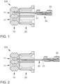
- the Figure 1 shows a connector 100 during the assembly of a collective seal 10 in the form of a mat seal 10 with an electrically conductive plug contact 30.
- the mat seal 10 has several through-openings 11 for a plug contact 30 each, which can be optionally assembled or left free.
- the mat seal 10 is held on a holding element 20 with corresponding openings 21.
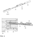
- the mat seal 10 and the holding element 20 are housed together in a connector housing 50, which in the view of Figure 3 is shown.
- the invention provides a connector 100 which is Figures 3 to 6 is shown, and which makes it possible to gently equip the collective seal 10 even with a connector 100 on the plug side with relatively thick plug contacts 30, without damaging the collective seal 10.
- the connector 100 is accommodated in a connector housing 50 which is located at the bottom of the Figure 3 is shown.
- a mat seal 10 is inserted into the connector housing 50 to protect or seal the interior of the connector housing 50 from external influences.
- the mat seal 10 is held by means of a holding element 20.
- the mat seal 10 is designed with at least one, preferably several, through opening(s) 11, in each of which an electrically conductive plug contact 30 can be received in order to provide electrical contact to the outside (e.g., to a plug socket).
- the invention is characterized in that the plug contact 30 is designed with an assembly aid 40 in order to support the plug contact 30 when passing through the through opening 11 of the collective seal 10.
- the assembly aid 40 serves to reduce the friction between the plug tip 31 of the contact plug 20 and the collective seal 10 when the plug contact 30 is inserted through the through-opening 11 in the collective seal 10. This prevents the plug tip 31 from penetrating the collective seal 10 because it is deflected by the assembly aid 40.
- the assembly aid 40 causes the plug contact 30 to slide along the surface of the mat seal 10 until the plug tip 31 has hit the through-opening 11 in the mat seal 30 and can then be gently inserted through this through-opening 11. This even enables automated assembly of the collective seal 10.
- a suitable material composition of the assembly aid 40 can cause a dampened or elastically yielding placement of the plug tip 31 on the surface of the collective seal 10 and further increase the angle of incidence ⁇ of the plug tip 31 on the surface of the collective seal 10 or reduce the contact angle ⁇ ' of the sliding surface 44 of the assembly aid 40 on the surface of the collective seal 10.
- the assembly aid 40 according to the invention can reduce the friction coefficient between the plug tip 31 and the collective seal 10 in an advantageous manner.
- the Figure 3 shows a possible embodiment outside the invention, according to which the assembly aid 40 can be designed as a removable cap 41 for the plug tip 31, which can be removed after the plug contact 30 has been passed through the through opening 11 of the collective seal 10.
- the assembly aid 40 can be made of a plastic, for example silicone.
- the assembly aid 40 can be applied to the plug tip 31 as a sheath 42 (see Figures 4 and 6 ), for example by means of an injection molding process or a coating process.
- the assembly aid 40 can be applied as a material layer 43, e.g. a lacquer layer, to the plug tip 31 of the plug contact 30.
- assembly aid 40 can be designed in the form of a section 41, 42, 43 of the plug tip 31 of the plug contact 30.
- the design of the mounting aid 40 is not limited to the examples shown. Rather, it is conceivable that the mounting aid 40 may have various rounded geometries that can provide a substantially smooth sliding surface 44. In principle, any plastic material that can enable a low coefficient of friction through its material pairing with the material of the mat seal 10 is conceivable as the material for the mounting aid 40.
- the assembly aid 20 in the form of a section 41, 42, 43 of the connector tip 31 can ensure that when the plug contact 31 is placed on the surface of the mat seal 10, the assembly aid 20 first comes into contact with the mat seal 10. If the through-opening 11 is not hit, the section 41, 42, 43 of the connector tip 31 will ensure that the connector tip 31 can slide off without puncturing the mat seal 10.
- the elastically flexible contact of the assembly aid 40 on the surface of the mat seal 10 also promotes the connector tip 31 sliding along the surface of the mat seal 10 until the connector tip 31 is correctly positioned on the through-opening 11.
- the invention can provide that the assembly aid 40 can have electrically conductive inserts 45, for example in the form of fibers, as is the case with Figure 4 schematically indicated. Conductive fibers, which can be distributed in the material of the assembly aid 40, are conceivable as inserts 45. This makes it possible for the assembly aid 40 to remain at the connector tip 31 in the finished connector 100.
- the (elastic) assembly aid 40 can be easily removed from the plug tip 31.
- an adhesion promoter surface structure e.g. in the form of a roughening, can be provided on the plug tip 31 of the plug contact 30 in order to ensure a better hold of the assembly aid 40 on the plug tip 31.
- a material-fit A connection between the assembly aid 40 and the connector tip 31 can be provided, for example, by heating the connector tip 31 before applying the assembly aid 40. If the assembly aid 40 has electrically conductive inserts 45, then it does not need to be removed. In this case, a material connection between the assembly aid 40 and the connector tip 31 can be advantageous.
Landscapes
- Engineering & Computer Science (AREA)
- Manufacturing & Machinery (AREA)
- Connector Housings Or Holding Contact Members (AREA)
Claims (5)
- Connecteur enfichable (100) destiné à fournir une connexion électrique, présentant :un joint collecteur (10) comportant au moins une ouverture de passage (11) et au moins un contact enfichable (30) électriquement conducteur,lequel peut être guidé à travers l'au moins une ouverture de passage (11) du joint collecteur (10),dans lequel le contact enfichable (30) est conçu avec un moyen d'aide au montage (40) pour soutenir le contact enfichable (30) lors du passage à travers l'ouverture de passage (11) du joint collecteur (10),dans lequel le moyen d'aide au montage (40) est conçu sous la forme d'une section (43) d'une pointe enfichable (31) du contact enfichable (30) afin de positionner le contact enfichable (30) au niveau de l'ouverture de passage (11) du joint collecteur (10) avant le passage à travers l'ouverture de passage (11),caractérisé en ceque le moyen d'aide au montage (40) est conçu sous la forme d'une couche de matériau (43) sur une pointe enfichable (31) du contact enfichable (30),dans lequel le moyen d'aide au montage (40) est appliqué sous la forme d'une couche de peinture.
- Connecteur enfichable (100) selon la revendication 1,
caractérisé en ce
que le moyen d'aide au montage (40) présente une surface de glissement (44) qui, par sa configuration géométrique et/ou sa composition de matériau, assure un impact du contact enfichable (30) sur la surface du joint collecteur (10) avec un angle d'incidence (α) plus grand par rapport à une normale à la surface du joint collecteur (10) que l'angle de frottement typique sur la surface du joint collecteur (10). - Connecteur enfichable (100) selon l'une des revendications précédentes,
caractérisé en ce
que le moyen d'aide au montage (40) est réalisé en une matière plastique ou en une silicone, et/ou en ce que le moyen d'aide au montage (40) présente des inserts (45) électriquement conducteurs. - Connecteur enfichable (100) selon l'une des revendications précédentes,
caractérisé en ce
que le contact enfichable (30) présente sur une pointe enfichable (31) une géométrie d'adhérence (32) afin de maintenir le moyen d'aide au montage (40) sur le contact enfichable (30) de manière à empêcher sa perte, au moins lors du passage du contact enfichable (30) à travers l'ouverture de passage (11) du joint collecteur (10). - Procédé destiné à fabriquer un connecteur enfichable (100), présentant :un joint collecteur (10) comportant au moins une ouverture de passage (11) et au moins un contact enfichable (30) électriquement conducteur,lequel est guidé à travers l'au moins une ouverture de passage (11) du joint collecteur (10),dans lequel, lors du passage du contact enfichable (30) à travers l'ouverture de passage (11) du joint collecteur (10), un moyen d'aide au montage (40) est utilisé pour guider de manière ciblée le contact enfichable (30) à travers l'ouverture de passage (11) du joint collecteur (10), dans lequel le moyen d'aide au montage (40) est réalisé sous la forme d'une section (43) d'une pointe enfichable (31) du contact enfichable (30) afin de positionner le contact enfichable (30) au niveau de l'ouverture de passage (11) du joint collecteur (10) avant le passage à travers l'ouverture de passage (11),caractérisé en ceque le moyen d'aide au montage (40) est réalisé sous la forme d'une couche de matériau (43) sur une pointe enfichable (31) du contact enfichable (30),dans lequel le moyen d'aide au montage (40) est appliqué sous la forme d'une couche de peinture sur une pointe enfichable (31) du contact enfichable (30).
Applications Claiming Priority (3)
| Application Number | Priority Date | Filing Date | Title |
|---|---|---|---|
| DE102017223593 | 2017-12-21 | ||
| DE102018209354.7A DE102018209354A1 (de) | 2017-12-21 | 2018-06-12 | Steckverbinder |
| PCT/EP2018/083253 WO2019120955A1 (fr) | 2017-12-21 | 2018-12-03 | Connecteur enfichable |
Publications (2)
| Publication Number | Publication Date |
|---|---|
| EP3729564A1 EP3729564A1 (fr) | 2020-10-28 |
| EP3729564B1 true EP3729564B1 (fr) | 2025-04-16 |
Family
ID=66768390
Family Applications (1)
| Application Number | Title | Priority Date | Filing Date |
|---|---|---|---|
| EP18814551.0A Active EP3729564B1 (fr) | 2017-12-21 | 2018-12-03 | Connecteur enfichable |
Country Status (4)
| Country | Link |
|---|---|
| EP (1) | EP3729564B1 (fr) |
| CN (1) | CN111758191B (fr) |
| DE (1) | DE102018209354A1 (fr) |
| WO (1) | WO2019120955A1 (fr) |
Families Citing this family (2)
| Publication number | Priority date | Publication date | Assignee | Title |
|---|---|---|---|---|
| DE102021001478A1 (de) | 2021-03-20 | 2022-09-22 | Kostal Kontakt Systeme Gmbh | Elektrischer Steckverbinder und Verfahren zum Konfektionieren einer elektrischen Anschlussleitung für einen solchen Steckverbinder |
| CN118610853B (zh) * | 2024-08-07 | 2024-11-08 | 顺科智连技术股份有限公司 | 一种两芯带屏蔽加热插头组装机 |
Family Cites Families (13)
| Publication number | Priority date | Publication date | Assignee | Title |
|---|---|---|---|---|
| FR2741204A1 (fr) * | 1995-11-14 | 1997-05-16 | Amp France | Assemblage de connecteur electrique |
| DE19651120C1 (de) * | 1996-12-09 | 1998-05-07 | Framatome Connectors Int | Kontaktelemente und Steckverbinder, insbesondere für Kabelbäume |
| JP2002164143A (ja) * | 2000-11-27 | 2002-06-07 | Sumitomo Wiring Syst Ltd | 防水コネクタにおける端子金具の挿抜方法及びこれに使用する治具 |
| JP2005317498A (ja) * | 2004-04-02 | 2005-11-10 | Sumitomo Wiring Syst Ltd | 防水コネクタ |
| JP4634165B2 (ja) * | 2005-01-31 | 2011-02-16 | セイコーインスツル株式会社 | 気密端子の製造方法 |
| WO2008005372A2 (fr) * | 2006-06-30 | 2008-01-10 | Molex Incorporated | Ensemble de connecteur électrique à structure d'étanchéité améliorée |
| US8113860B2 (en) * | 2009-09-04 | 2012-02-14 | Graeme Richard Sandwith | High power multi-pin electrical connector |
| US9153899B2 (en) * | 2013-10-08 | 2015-10-06 | Delphi Technologies, Inc. | Electrical connector assembly with terminal retaining seal |
| EP3057183B1 (fr) * | 2015-02-12 | 2019-09-11 | Aptiv Technologies Limited | Connecteur étanche |
| WO2017015285A1 (fr) * | 2015-07-23 | 2017-01-26 | Molex, Llc | Raccord de borne |
| US10044132B2 (en) * | 2016-04-22 | 2018-08-07 | Yazaki North America, Inc. | Cable seal connector with punch-out capability for unused cavities |
| CN206727302U (zh) * | 2017-04-14 | 2017-12-08 | 李信 | 一种玻璃烧结密封插头 |
| EP3410542B1 (fr) * | 2017-05-30 | 2020-12-30 | Aptiv Technologies Limited | Dispositif de protection et ensemble de bornes |
-
2018
- 2018-06-12 DE DE102018209354.7A patent/DE102018209354A1/de not_active Ceased
- 2018-12-03 EP EP18814551.0A patent/EP3729564B1/fr active Active
- 2018-12-03 CN CN201880082418.8A patent/CN111758191B/zh active Active
- 2018-12-03 WO PCT/EP2018/083253 patent/WO2019120955A1/fr not_active Ceased
Also Published As
| Publication number | Publication date |
|---|---|
| DE102018209354A1 (de) | 2019-06-27 |
| CN111758191A (zh) | 2020-10-09 |
| WO2019120955A1 (fr) | 2019-06-27 |
| CN111758191B (zh) | 2021-12-10 |
| EP3729564A1 (fr) | 2020-10-28 |
Similar Documents
| Publication | Publication Date | Title |
|---|---|---|
| DE102010002765A1 (de) | Gehäusegrundelement eines mehrteiligen Gehäuses und Verfahren zur Montage eines Gehäuses | |
| EP2869674B1 (fr) | Poignée de porte de véhicule doté d'un bloc électronique sur une carte de circuits imprimés souple | |
| EP1869743A1 (fr) | Dispositif et procede pour le passage universel de cables | |
| WO2008003664A1 (fr) | Unité de détection, et son procédé de production | |
| DE102019112923A1 (de) | Selbstausrichtendes System zur Befestigung einer Verkleidungsplatte an einer Fahrzeugtüranordnung | |
| EP3729564B1 (fr) | Connecteur enfichable | |
| DE102010025689A1 (de) | Antriebseinheit für eine Scheibenwischvorrichtung in einem Fahrzeug und Gehäuse für eine Antriebseinheit | |
| EP3597018B1 (fr) | Module électronique de contrôle et procédé de fabrication d'un module électronique de contrôle | |
| EP1608994A1 (fr) | Ensemble capteur d'un systeme d'aide au stationnement | |
| DE102013112846A1 (de) | Anordnung zum Befestigen eines ersten Karosserieteils an einem zweiten Karosserieteil eines Kraftfahrzeugs | |
| DE102012218463A1 (de) | Verfahren zur Herstellung eines Elektronikmoduls und Elektronikmodul | |
| DE102013014526A1 (de) | Elektronikeinheit für eine Mikrofoneinheit, Mikrofoneinheit, Nutzen zur Herstellung einer Elektronikeinheit und Verfahren zur Herstellung einer Mikrofoneinheit | |
| EP3837740B1 (fr) | Connecteur électrique | |
| EP2463964B1 (fr) | Système d'étanchéification | |
| WO2018006894A1 (fr) | Procédé de fabrication d'un substrat de composant électronique pour des applications automobiles | |
| DE202006009247U1 (de) | Gehäuse für ein Türschloss mit Anschlussadapter | |
| DE102011005660A1 (de) | Steckverbindereinheit | |
| DE202009005059U1 (de) | Kraftfahrzeugschloss bestehend aus mechanischen und elektrischen, elektromotorischen und/oder elektronischen Bauteilen | |
| DE102012108859B4 (de) | Elektronikmodul | |
| DE102014010368A1 (de) | Montageeinrichtung und Verfahren zum Montieren eines ersten Bauelements an einem zweiten Bauelement eines Kraftwagens, insbesondere eines Personenkraftwagens | |
| EP2653018B1 (fr) | Appareil de commande et procédé de fabrication d'un appareil de commande | |
| DE102013215074B4 (de) | Befestigungsvorrichtung für längliche Gegenstände sowie Befestigungssystem | |
| DE102017210979B4 (de) | Verfahren zur Herstellung eines elektrischen Bauteils und elektrisches Bauteil | |
| DE102015004000A1 (de) | Pyrotechnische Aktuatoreinheit, Gassackmodul mit einer solchen Aktuatoreinheit sowie Verfahren zur Herstellung einer pyrotechnischen Aktuatoreinheit | |
| DE102014210195B4 (de) | Anbindung einer Fensterheberantriebseinrichtung in einer Kraftfahrzeugtür |
Legal Events
| Date | Code | Title | Description |
|---|---|---|---|
| STAA | Information on the status of an ep patent application or granted ep patent |
Free format text: STATUS: UNKNOWN |
|
| STAA | Information on the status of an ep patent application or granted ep patent |
Free format text: STATUS: THE INTERNATIONAL PUBLICATION HAS BEEN MADE |
|
| PUAI | Public reference made under article 153(3) epc to a published international application that has entered the european phase |
Free format text: ORIGINAL CODE: 0009012 |
|
| STAA | Information on the status of an ep patent application or granted ep patent |
Free format text: STATUS: REQUEST FOR EXAMINATION WAS MADE |
|
| 17P | Request for examination filed |
Effective date: 20200721 |
|
| AK | Designated contracting states |
Kind code of ref document: A1 Designated state(s): AL AT BE BG CH CY CZ DE DK EE ES FI FR GB GR HR HU IE IS IT LI LT LU LV MC MK MT NL NO PL PT RO RS SE SI SK SM TR |
|
| AX | Request for extension of the european patent |
Extension state: BA ME |
|
| DAV | Request for validation of the european patent (deleted) | ||
| DAX | Request for extension of the european patent (deleted) | ||
| STAA | Information on the status of an ep patent application or granted ep patent |
Free format text: STATUS: EXAMINATION IS IN PROGRESS |
|
| 17Q | First examination report despatched |
Effective date: 20220211 |
|
| GRAP | Despatch of communication of intention to grant a patent |
Free format text: ORIGINAL CODE: EPIDOSNIGR1 |
|
| STAA | Information on the status of an ep patent application or granted ep patent |
Free format text: STATUS: GRANT OF PATENT IS INTENDED |
|
| INTG | Intention to grant announced |
Effective date: 20241111 |
|
| GRAS | Grant fee paid |
Free format text: ORIGINAL CODE: EPIDOSNIGR3 |
|
| GRAA | (expected) grant |
Free format text: ORIGINAL CODE: 0009210 |
|
| STAA | Information on the status of an ep patent application or granted ep patent |
Free format text: STATUS: THE PATENT HAS BEEN GRANTED |
|
| P01 | Opt-out of the competence of the unified patent court (upc) registered |
Free format text: CASE NUMBER: APP_6916/2025 Effective date: 20250211 |
|
| AK | Designated contracting states |
Kind code of ref document: B1 Designated state(s): AL AT BE BG CH CY CZ DE DK EE ES FI FR GB GR HR HU IE IS IT LI LT LU LV MC MK MT NL NO PL PT RO RS SE SI SK SM TR |
|
| REG | Reference to a national code |
Ref country code: GB Ref legal event code: FG4D Free format text: NOT ENGLISH |
|
| REG | Reference to a national code |
Ref country code: CH Ref legal event code: EP Ref country code: DE Ref legal event code: R096 Ref document number: 502018015751 Country of ref document: DE |
|
| REG | Reference to a national code |
Ref country code: IE Ref legal event code: FG4D Free format text: LANGUAGE OF EP DOCUMENT: GERMAN |
|
| REG | Reference to a national code |
Ref country code: NL Ref legal event code: MP Effective date: 20250416 |
|
| PG25 | Lapsed in a contracting state [announced via postgrant information from national office to epo] |
Ref country code: NL Free format text: LAPSE BECAUSE OF FAILURE TO SUBMIT A TRANSLATION OF THE DESCRIPTION OR TO PAY THE FEE WITHIN THE PRESCRIBED TIME-LIMIT Effective date: 20250416 |
|
| PG25 | Lapsed in a contracting state [announced via postgrant information from national office to epo] |
Ref country code: FI Free format text: LAPSE BECAUSE OF FAILURE TO SUBMIT A TRANSLATION OF THE DESCRIPTION OR TO PAY THE FEE WITHIN THE PRESCRIBED TIME-LIMIT Effective date: 20250416 Ref country code: PT Free format text: LAPSE BECAUSE OF FAILURE TO SUBMIT A TRANSLATION OF THE DESCRIPTION OR TO PAY THE FEE WITHIN THE PRESCRIBED TIME-LIMIT Effective date: 20250818 Ref country code: ES Free format text: LAPSE BECAUSE OF FAILURE TO SUBMIT A TRANSLATION OF THE DESCRIPTION OR TO PAY THE FEE WITHIN THE PRESCRIBED TIME-LIMIT Effective date: 20250416 |
|
| REG | Reference to a national code |
Ref country code: LT Ref legal event code: MG9D |
|
| PG25 | Lapsed in a contracting state [announced via postgrant information from national office to epo] |
Ref country code: NO Free format text: LAPSE BECAUSE OF FAILURE TO SUBMIT A TRANSLATION OF THE DESCRIPTION OR TO PAY THE FEE WITHIN THE PRESCRIBED TIME-LIMIT Effective date: 20250716 Ref country code: GR Free format text: LAPSE BECAUSE OF FAILURE TO SUBMIT A TRANSLATION OF THE DESCRIPTION OR TO PAY THE FEE WITHIN THE PRESCRIBED TIME-LIMIT Effective date: 20250717 |
|
| PG25 | Lapsed in a contracting state [announced via postgrant information from national office to epo] |
Ref country code: PL Free format text: LAPSE BECAUSE OF FAILURE TO SUBMIT A TRANSLATION OF THE DESCRIPTION OR TO PAY THE FEE WITHIN THE PRESCRIBED TIME-LIMIT Effective date: 20250416 |
|
| PG25 | Lapsed in a contracting state [announced via postgrant information from national office to epo] |
Ref country code: BG Free format text: LAPSE BECAUSE OF FAILURE TO SUBMIT A TRANSLATION OF THE DESCRIPTION OR TO PAY THE FEE WITHIN THE PRESCRIBED TIME-LIMIT Effective date: 20250416 |
|
| PG25 | Lapsed in a contracting state [announced via postgrant information from national office to epo] |
Ref country code: HR Free format text: LAPSE BECAUSE OF FAILURE TO SUBMIT A TRANSLATION OF THE DESCRIPTION OR TO PAY THE FEE WITHIN THE PRESCRIBED TIME-LIMIT Effective date: 20250416 |
|
| PG25 | Lapsed in a contracting state [announced via postgrant information from national office to epo] |
Ref country code: RS Free format text: LAPSE BECAUSE OF FAILURE TO SUBMIT A TRANSLATION OF THE DESCRIPTION OR TO PAY THE FEE WITHIN THE PRESCRIBED TIME-LIMIT Effective date: 20250716 |
|
| PG25 | Lapsed in a contracting state [announced via postgrant information from national office to epo] |
Ref country code: IS Free format text: LAPSE BECAUSE OF FAILURE TO SUBMIT A TRANSLATION OF THE DESCRIPTION OR TO PAY THE FEE WITHIN THE PRESCRIBED TIME-LIMIT Effective date: 20250816 |
|
| PG25 | Lapsed in a contracting state [announced via postgrant information from national office to epo] |
Ref country code: LV Free format text: LAPSE BECAUSE OF FAILURE TO SUBMIT A TRANSLATION OF THE DESCRIPTION OR TO PAY THE FEE WITHIN THE PRESCRIBED TIME-LIMIT Effective date: 20250416 |
|
| PGFP | Annual fee paid to national office [announced via postgrant information from national office to epo] |
Ref country code: GB Payment date: 20251223 Year of fee payment: 8 |
|
| PG25 | Lapsed in a contracting state [announced via postgrant information from national office to epo] |
Ref country code: DK Free format text: LAPSE BECAUSE OF FAILURE TO SUBMIT A TRANSLATION OF THE DESCRIPTION OR TO PAY THE FEE WITHIN THE PRESCRIBED TIME-LIMIT Effective date: 20250416 Ref country code: SM Free format text: LAPSE BECAUSE OF FAILURE TO SUBMIT A TRANSLATION OF THE DESCRIPTION OR TO PAY THE FEE WITHIN THE PRESCRIBED TIME-LIMIT Effective date: 20250416 |
|
| PGFP | Annual fee paid to national office [announced via postgrant information from national office to epo] |
Ref country code: FR Payment date: 20251223 Year of fee payment: 8 |
|
| REG | Reference to a national code |
Ref country code: DE Ref legal event code: R097 Ref document number: 502018015751 Country of ref document: DE |
|
| PG25 | Lapsed in a contracting state [announced via postgrant information from national office to epo] |
Ref country code: CZ Free format text: LAPSE BECAUSE OF FAILURE TO SUBMIT A TRANSLATION OF THE DESCRIPTION OR TO PAY THE FEE WITHIN THE PRESCRIBED TIME-LIMIT Effective date: 20250416 |
|
| PG25 | Lapsed in a contracting state [announced via postgrant information from national office to epo] |
Ref country code: EE Free format text: LAPSE BECAUSE OF FAILURE TO SUBMIT A TRANSLATION OF THE DESCRIPTION OR TO PAY THE FEE WITHIN THE PRESCRIBED TIME-LIMIT Effective date: 20250416 |
|
| PG25 | Lapsed in a contracting state [announced via postgrant information from national office to epo] |
Ref country code: RO Free format text: LAPSE BECAUSE OF FAILURE TO SUBMIT A TRANSLATION OF THE DESCRIPTION OR TO PAY THE FEE WITHIN THE PRESCRIBED TIME-LIMIT Effective date: 20250416 Ref country code: SK Free format text: LAPSE BECAUSE OF FAILURE TO SUBMIT A TRANSLATION OF THE DESCRIPTION OR TO PAY THE FEE WITHIN THE PRESCRIBED TIME-LIMIT Effective date: 20250416 |
|
| PG25 | Lapsed in a contracting state [announced via postgrant information from national office to epo] |
Ref country code: IT Free format text: LAPSE BECAUSE OF FAILURE TO SUBMIT A TRANSLATION OF THE DESCRIPTION OR TO PAY THE FEE WITHIN THE PRESCRIBED TIME-LIMIT Effective date: 20250416 |
|
| PLBE | No opposition filed within time limit |
Free format text: ORIGINAL CODE: 0009261 |
|
| STAA | Information on the status of an ep patent application or granted ep patent |
Free format text: STATUS: NO OPPOSITION FILED WITHIN TIME LIMIT |
|
| REG | Reference to a national code |
Ref country code: CH Ref legal event code: L10 Free format text: ST27 STATUS EVENT CODE: U-0-0-L10-L00 (AS PROVIDED BY THE NATIONAL OFFICE) Effective date: 20260225 |
|
| 26N | No opposition filed |
Effective date: 20260119 |
|
| PGFP | Annual fee paid to national office [announced via postgrant information from national office to epo] |
Ref country code: DE Payment date: 20251231 Year of fee payment: 8 |