EP3729577B1 - Bloc d'insertion et système d'étanchéité comprenant ledit bloc d'insertion - Google Patents
Bloc d'insertion et système d'étanchéité comprenant ledit bloc d'insertion Download PDFInfo
- Publication number
- EP3729577B1 EP3729577B1 EP18893281.8A EP18893281A EP3729577B1 EP 3729577 B1 EP3729577 B1 EP 3729577B1 EP 18893281 A EP18893281 A EP 18893281A EP 3729577 B1 EP3729577 B1 EP 3729577B1
- Authority
- EP
- European Patent Office
- Prior art keywords
- insert
- plug
- insert block
- radius
- passage
- Prior art date
- Legal status (The legal status is an assumption and is not a legal conclusion. Google has not performed a legal analysis and makes no representation as to the accuracy of the status listed.)
- Active
Links
Images


Classifications
-
- F—MECHANICAL ENGINEERING; LIGHTING; HEATING; WEAPONS; BLASTING
- F16—ENGINEERING ELEMENTS AND UNITS; GENERAL MEASURES FOR PRODUCING AND MAINTAINING EFFECTIVE FUNCTIONING OF MACHINES OR INSTALLATIONS; THERMAL INSULATION IN GENERAL
- F16L—PIPES; JOINTS OR FITTINGS FOR PIPES; SUPPORTS FOR PIPES, CABLES OR PROTECTIVE TUBING; MEANS FOR THERMAL INSULATION IN GENERAL
- F16L5/00—Devices for use where pipes, cables or protective tubing pass through walls or partitions
- F16L5/02—Sealing
- F16L5/04—Sealing to form a firebreak device
-
- H—ELECTRICITY
- H02—GENERATION; CONVERSION OR DISTRIBUTION OF ELECTRIC POWER
- H02G—INSTALLATION OF ELECTRIC CABLES OR LINES, OR OF COMBINED OPTICAL AND ELECTRIC CABLES OR LINES
- H02G3/00—Installations of electric cables or lines or protective tubing therefor in or on buildings, equivalent structures or vehicles
- H02G3/22—Installations of cables or lines through walls, floors or ceilings, e.g. into buildings
-
- E—FIXED CONSTRUCTIONS
- E04—BUILDING
- E04B—GENERAL BUILDING CONSTRUCTIONS; WALLS, e.g. PARTITIONS; ROOFS; FLOORS; CEILINGS; INSULATION OR OTHER PROTECTION OF BUILDINGS
- E04B1/00—Constructions in general; Structures which are not restricted either to walls, e.g. partitions, or floors or ceilings or roofs
- E04B1/62—Insulation or other protection; Elements or use of specified material therefor
- E04B1/92—Protection against other undesired influences or dangers
- E04B1/94—Protection against other undesired influences or dangers against fire
-
- F—MECHANICAL ENGINEERING; LIGHTING; HEATING; WEAPONS; BLASTING
- F16—ENGINEERING ELEMENTS AND UNITS; GENERAL MEASURES FOR PRODUCING AND MAINTAINING EFFECTIVE FUNCTIONING OF MACHINES OR INSTALLATIONS; THERMAL INSULATION IN GENERAL
- F16L—PIPES; JOINTS OR FITTINGS FOR PIPES; SUPPORTS FOR PIPES, CABLES OR PROTECTIVE TUBING; MEANS FOR THERMAL INSULATION IN GENERAL
- F16L5/00—Devices for use where pipes, cables or protective tubing pass through walls or partitions
- F16L5/02—Sealing
- F16L5/10—Sealing by using sealing rings or sleeves only
Definitions
- the present invention relates to an insert block for sealing around a cable, wire or pipe, and a sealing system comprising said insert block.
- One frequently used sealing system that provide a reliable sealing of cables, wires or pipes extending through partition walls involves a metal frame permanently installed in the partition wall to provide a passage of a predetermined size for the cables, wires or pipes in the desired area of the partition wall.
- the cables, wires or pipes are during installation lead through the frame.
- the space within the frame is during installation of the sealing system filled with insert blocks packed in layers within the frame to completely fill the space within the frame.
- Each insert block consists of two insert block halves each provided with a semi-circular groove in one side of the block half such that a circular passage is formed through the insert block when the two block halves are put together.
- Each cable, wire or pipe extending through the frame is fitted in an insert block and packed within the frame.
- the outside dimensions of the insert blocks are selected so that a predetermined number of insert blocks have a size corresponding to the space within the frame.
- a pressure applying device is arranged in the top part of the frame. The pressure applying device, upon activation, applies a pressure on the blocks to press the blocks together and provide the desired sealing around the cables, wires or pipes within the frame.
- WO 2017/176203 A1 relates to an insert half, an insert block and the use of an insert block for sealing around a cable, pipe or wire extending through a partition wall.
- the insert half is used in combination with at least one insert to adapt the insert halves to cables, wires or pipes with different radius and thereby provide a reliable sealing around the periphery of the cable, wire or pipe.
- Document US6062267 discloses a telescopic conduit in which the cables (Element 23) can be accommodated, however it does not provide any function of sealing the circular passage when the cables are not inserted.
- the frame preferably is selected slightly larger than actually required.
- the frame is then filled with insert halves without any pipe, wire or cable extending through the insert halves and in order to seal the space within the frame each groove is sealed by an insert plug fitted in the recess to close the groove.
- the insert plug has a radius corresponding to the radius of the groove to ensure that the groove is sealed once the pressure is applied.
- the present invention relates to an insert block for sealing around a cable, pipe or wire that to at least some extent fulfils the need defined above.
- the insert block according to the invention comprises:
- the general bmw with the present invention is to improve the sealing of the passage through the insert block when no cable, wire or pipe is lead through the insert block.
- the insert plug according to the invention turned out to improve the sealing of the passage through the insert block since the insert plug adapts to the extension along axis A of the insert block.
- the insert plug has a length along axis A that is adjustable within the range from substantially equal to the distance between the first and second end of the insert block halves to a length exceeding the distance between the first and second end of the insert block halves.
- the insert block halves are made of elastic material and the at least two insert plug elements are made of a less elastic material than the insert halves. This embodiment further improves the sealing of the passage since the insert plug formed of a less elastic material than the insert block will provide the intended shape and seal the passage instead of being deformed.
- the at least one of the at least two insert plug elements are made of a non-elastic material. This embodiment improves the sealing since the insert plug not will be deformed when a pressure is applied.
- the at least two insert plug elements are connected by a male / female configuration such that the length along axis A is adjustable, and said section of the plug that has a circular cross section with a radius corresponding to the radius of the passage extend across the at least two insert plug elements.
- the insert plug has a first end and a second end and comprises a first flange arranged in the first end and extending in radial direction from axis A and a second flange arranged in the second end and extending in radial direction from the axis A, said flanges has a radius exceeding the radius of the circular passage formed in the insert block such that the first and second flange are supported against the first and second end surfaces of the insert halves.
- This embodiment of the inset plug is advantageous since the flanges ensures that the insert plug will expand together with the insert block when the pressure is applied on the insert blocks within the frame.
- each of said insert half furthermore comprises at least one insert removably arranged within said groove
- said insert is formed by at least two elements bonded to each other side by side and are extending substantially transverse to axis A, wherein said inserts have an outside shape corresponding to the shape of the groove and the recesses such that the insert could be arranged anywhere along the groove, wherein each element comprises a semi-circular inside surface with different radius such that a passage with different radius co-axial to axis A is formed to adapt the radius of the passage through said insert block, and the sealing plug is arranged to seal the passage formed by the at least one insert in each insert block half.
- the width of the recesses along axis A correspond to the width of one element such that one element fit in one recess.
- the insert comprises the same number of elements as the number of recesses in the insert halves.
- the insert block comprises two inserts in each insert half, one insert is arranged adjacent to the first end of the insert half and the other insert is arranged adjacent to the second end of the insert block, and the section of the plug that has a circular cross section with a radius corresponding to the radius of the passage is arranged between the two inserts
- the insert plug has a first end and a second end and comprises a first flange arranged in the first end and extending in radial direction from axis A and a second flange arranged in the second end and extending in radial direction from the axis A, said flanges has a radius corresponding to the radius of the circular passage formed by the at least one insert or a radius corresponding to the radius of the recesses formed in the groove such that the passage through the insert is sealed by the insert plug.
- This embodiment of the inset plug is advantageous since the flanges ensures that the insert plug will expand together with the insert block when the pressure is applied on the insert blocks within the frame.
- the length of the insert plug along axis A is adjustable to such that the first and / or second flange fit in the recesses adjacent to the first and second end of the insert block halves or between adjacent elements of the at least one insert arranged within the groove of the insert halves.
- the present invention furthermore relates to a sealing system comprising:
- the claimed sealing system provides improved sealing of the space within the frame since the new insert block provides a more efficient sealing of the insert block when no cable, wire or pipe is fitted in the insert block which happens frequently since the frame preferably is selected slightly larger than the present need to make room for future additional installations of cables, wires or pipes.
- FIG 1 a sealing system 1 for sealing of cables 2, wires or pipes extending through a not illustrated partition wall is illustrated.
- the system involves a metal frame 3 intended to be permanently installed in the partition wall to provide a passage of a predetermined size in the partition wall.
- the cables, wires or pipes that need to pass through the partition wall are during installation lead through the frame.
- an insert block 4 comprising two substantially identical insert block halves 10, is fitted around each of the cables, wires or pipes extending through the frame.
- the insert blocks, and the cable, wire or pipe extending through the insert block, are packed in layers within the frame to completely fill the space within the frame.
- the insert blocks have substantially square cross sectional shape and the outside dimensions of the insert blocks are selected so that a predetermined number of insert blocks have a size corresponding to the space within the frame to fill the space within the frame and provide the desired sealing of the passage in the partition wall.
- the different layers of insert blocks are separated by a guiding metal plate 5 in order to ensure that the layers remain in the intended position within the frame 3 when pressure is applied on the sealing system.
- the insert blocks could be replaced by a solid elastic rectangular block to fill the remaining spaces within the frame alternatively an insert block according to the present invention could be used.
- the insert block according to the invention is described in more detail further down in the description.
- a pressure applying device 6 is arranged in the top part of the frame.
- the pressure applying device comprises a plate 7 arranged on each side of an elastic member and threaded shafts 8 extending through the elastic member.
- the elastic member When the elastic member is compressed between the plates by the shafts and nuts arranged on the shaft the elastic element expand such that a pressure is applied on the layer packed within the frame 3 thereby eliminating gaps between the insert blocks and sealing the space within the frame.
- Different types of pressure applying devices are available and the described device could be replaced by anyone of the available devices.
- FIG. 2 A second embodiment of a sealing system 100 is illustrated in figure 2 .
- the rectangular frame is replaced by a circular metal frame 103 intended to be permanently installed in the partition wall.
- the pressure applying device 103 is arranged around the inner periphery of the frame.
- a rectangular opening 104 is formed for the insert block, or insert blocks, such that the pressure applying device is enclosing the insert block or insert blocks and cables.
- the above described insert blocks are fitted around the cables, wires and pipes and arranged within the opening in the pressure applying device such that the opening is filled completely before pressure is applied and the space within the frame is sealed.
- FIG. 3a and 3b An exploded view of a first embodiment of selected parts of an insert block according to the invention is illustrated in figure 3a and 3b .
- Each insert block comprises two identical insert halves 10, only one is illustrated in the figures to more clearly illustrate the different parts.
- Each insert half 10 comprises a rectangular insert half body 11 illustrated in figure 3a and 3b .
- the body 11 has a first end surface 12 and a second end surface 13 arranged on the opposite side of the rectangular body.
- a semi-circular groove 15 is formed in the body such that a circular passage is generated through the insert block when two identical block halves are arranged together with the grooves 15 and flat sides 14 of each insert block half facing each other.
- the longitudinal central axis A of the semi-cylindrical groove is arranged parallel to the flat side 14 of the body, as well as coaxial with a longitudinal central axis of the insert block formed of two identical insert halves 10.
- the diameter of the semi-cylindrical groove is smaller than the width of the insert body so that an elongated contact surface 16 is formed along each side of the groove 15.
- the contact surfaces 16 of two adjacent insert block halves will be in contact with each other thereby enclosing a cable, wire or pipe arranged in the groove.
- the body 11 is made of a pressure, water and heat resistant elastic rubber composition adapted to the specific demands on this type of sealing systems.
- the dimensions of the insert block half are preferably selected so that the insert block will have a square cross sectional shape, but other shapes could be used as long at the size of the insert blocks correspond to the dimensions of the frame in the partition wall.
- the insert block furthermore comprises an insert sealing plug 20 intend to close the passage when no cable, wire or pipe is extending through the insert block.
- the insert plug is illustrated in figure 3a .
- the insert plug 20 comprises two insert plug elements 21, 22 movably connected to each other such that the length of the insert plug along axis A is adjustable.
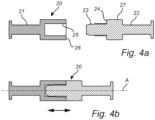
- the two insert plug elements 21, 22 are movably fitted to each other by a male/female configuration illustrated in figure 4a and 4b .
- One of the insert plug elements 22 comprises a circular protrusion 23 extending in axial direction from a side 24 of the insert plug element intended to be facing a corresponding side on the adjacent insert plug element 21, and the other insert plug element 21 comprises a corresponding circular recess 25 formed in a side 26 of the insert plug element intended to be facing the corresponding side on the other insert plug element.
- the circular protrusion 23 is fitted in the circular recess 25 such that the two insert plug elements are movable in relation to each other along the axial direction A to adjust the axial length of the insert plug.
- the cross sectional shape of the male/female configuration could however be modified as long as the first and second insert plug element fit together and provide the desired movability along axis A.
- the insert plug has a central circular section 27 with a radius corresponding to the radius of the groove 15 to seal the passage, and adjacent first 28 and second section 29 with a smaller radius arranged on opposite sides of the central section 27.
- the axial length of the central section could be modified. In the illustrated embodiment the central section extends across both the first 21 and second 22 insert plug element but this is not necessary to ensure the desired function of insert plug.
- the first and second section extend to the respective ends of the insert half body such that the length of the insert plug corresponds to the length along axis A of the insert half body.
- a flange 30 extend in radial direction from axis A.
- the flanges are intended to be arranged adjacent to the first and second end surface of the insert half bodies such that the insert plug elements are forced to move together with the insert block body when the pressure is applied within the frame to seal the space within the frame and the insert blocks are forced to expand along the axial direction A.
- the length of the insert plug is reduced and the flanges arranged within the groove close to the respective end surface of the insert half bodies.
- the flange then has a radius corresponding to the radius of the groove.
- the insert plug could also be modified such that the central section is extended all the way to the side surfaces of the insert block.
- the first and second section as well as the flanges are then consequently not needed.
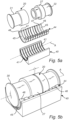
- FIG 5a and 5b a second embodiment of an insert block according to the invention is illustrated.
- the insert half body 40 is identical to the previously described embodiment of the insert half body but along the groove 15, a number of recesses 41 extending substantially transverse to the axis A are formed in the groove.
- the number of recesses 41 is ten, but the actual number could be both higher and smaller. All the recesses have the same width along the groove and a substantially uniform shape.
- the recesses are arranged side by side along the entire groove such that the groove will have an undulating shape.
- Each insert half furthermore comprises at least one insert 44 intended to be arranged within the groove 15.
- the general bmw with the at least one insert 44 arranged within the groove 15 is to make it possible to adapt the size, i.e. the radius, of the passage through the insert block.
- a first embodiment of the insert 44 is illustrated in figure 5a and 5b .
- the insert 44 is formed by at least two elements. However, the illustrated insert comprises ten elements 45.
- the elements 45 are arranged side by side along axis A, and bonded to each other.
- Each element 45 has the shape of a half-circular arc with an outer peripheral shape and dimension corresponding to the shape and dimension of the recesses 41 in the groove 15 such that the insert could be arranged and maintained in the groove anywhere along the groove.
- each element 45 of the insert 44 a semi-circular passage co-axial to axis A is formed such that a circular passage is formed when to identical inserts 44 arranged in the two insert halves are fitted together with the grooves 15 of the insert halves facing each other.
- an end surface 46 is formed that will be in contact with the end surface 46 of a corresponding element 45 of a second insert half.
- the semi-circular passage formed by the different elements 45 have different radius such that different elements 45 will fit cables, wires or pipes with different radius.
- the elements 45 with a semi-circular passage not corresponding to the cable, wire or pipe are teared from the insert 44 to only maintain the elements 45 with the desired radius such that the passage thereby is adapted to the particular cable, wire or pipe.
- the number of elements 45 of the insert is either less than the number of recesses in the insert half bodies 40, equal to the number of recesses 41 or larger than the number of recesses depending on the desired number of different radiuses the insert 44 is intended to be used for.
- the embodiment of the insert block illustrated in figure 5a and 5b comprises ten elements each having a semi-circular passage with different radius.
- the different elements 45 of the inserts 44 are bounded to each other side by side.
- the bounding 47 is preferably thin to facilitate removal of selected elements 45 to adapt the insert to the specific cable, wire or pipe.
- the different elements 45 of the inserts are arranged such that the two elements with the smallest radius of the semi-circular passages are arranged in opposite ends of the insert, the element with the third smallest radius is arranged adjacent to the element with the smallest radius on the side of the element that is facing the element with the second smallest radius, the element with the fourth smallest radius is arranged adjacent to the element with the second smallest radius on the side facing the element with the smallest radius and the remaining elements are arranged correspondingly in alternating ends of the insert adjacent to the elements with smaller radius.
- the illustrated and described configuration of the different elements forming the insert generates a larger space within the centre of the insert block that makes it possible to use an insert plug 20 with many similarities to the insert plug described above to seal the passage through the insert block.
- the insert plug 20 in this embodiment comprises two insert plug elements 21, 22 movably connected to each other by a male/female configuration.
- the insert plug has the central circular section 27 with a length along the axial direction A selected in combination with a suitable radius such that the central section fit in the space formed in the centre of the insert block.
- the radius of the central circular section is selected to correspond to the radiuses of the passage formed by two of the elements in the area close to the centre of the insert block where the central circular section is arranged when the insert plug is fitted in the insert block.
- the central circular section of the insert half should provide a tight fitting with two of the elements to seal the passage.
- the insert plug comprises adjacent first and second section with a smaller radius arranged on opposite sides of the central section.
- the radius of the first and second section must be smaller, or equal, to the smallest radius of the elements in the insert in the area of the first and second section to make it possible to fit the insert plug in the insert block.
- the axial length of the central section could be modified as long as its radius correspond to the smallest radius along the extension of the central section to make it possible to fit the insert plug in the insert block.
- the first and second section extend to the respective ends of the insert half body such that the length of the insert plug corresponds to the length of the insert half body.
- a flange extend in radial direction from axis A.
- the flanges have a slightly larger radius than the elements in the area of the flanges such that first and second flange provide a tight sealing in the respective end of the passage formed by the inserts.
- the first and second flange are preferably arranged close to the first and second end surface of the insert block. The first and second insert plug element are forced to move together with the insert block body and the inserts when the pressure is applied within the frame to seal the space within the frame.
- the insert In order to ensure a reliable configuration of the insert in the groove of the insert half body, the insert always comprises at least two elements to be maintained in an effective way within the recesses of the groove. If the insert illustrated in figure 5a and 5b is used, one of the elements is the one that correspond exactly to the present cable, wire or pipe and the second one the element that has a passage that is slightly larger than the present cable, wire or pipe.
- each insert half comprises at least two inserts arranged adjacent to the respective end surfaces of the insert half body to seal the cable, wire or pipe at two different locations along the cable, wire or pipe. This configuration is illustrated in figure 6a and 6b .
- the insert during installation is torn to form two inserts that preferably are arranged in each end of the groove to provide two sealing positions along the groove.
- the genius design of the insert 44 comprising a number of elements arranged such that the two elements with adjacent radius of the semi-circular passage are arranged in alternating ends of the insert make it possible to tear the insert so that the element which will provide the perfect fit and the adjacent element could be arranged in one end the groove, and the element slightly larger and the thereto adjacent element are arranged in the opposite end of the groove.
- the sealing system formed by this insert half provide a reliable sealing around the cable, wire or pipe once pressure is applied by the pressure applying device since sealing is provided at two different positions along the cable, wire or pipe. This is illustrated in figure 6a and 6b .
- two separate substantially identical inserts comprising the desired number of elements are manufactured an arranged in the respective ends of the groove could be used.
- the illustrated and described configuration of the two inserts 50 generates a larger space within the centre of the insert block.
- the passage in the centre of the insert block is formed by the groove 15 in the insert half body 50 and consequently has a constant radius between the two inserts.
- the insert plug 20 also in this embodiment comprises two insert plug elements 21, 22 movably connected to each other by a male/female configuration.
- the insert plug has a central circular section with a length along the axial direction A selected such that the central section fit in the space formed between the two inserts.
- the radius of the central circular section is selected to correspond to the radius of the groove in the insert half bodies.
- the central circular section of the insert half should provide a tight fitting to the groove to seal the passage.
- the insert plug comprises adjacent first and second section with a smaller radius arranged on opposite sides of the central section.
- the radius of the first and second section must be smaller, or equal, to the smallest radius of the elements in the two inserts to make it possible to fit the insert plug in the insert block.
- the axial length of the central section could be modified as long as it fit between the inserts in the insert block halves.
- the first and second section extend to the respective ends of the insert half body such that the length of the insert plug corresponds to the length of the insert half body.
- a flange extend in radial direction from axis A.
- the flanges have a slightly larger radius than the elements in the area of the flanges such that first and second flange provide a tight sealing in the respective end of the passage formed by the two inserts.
- the first and second flange are preferably arranged close to the first and second end surface of the insert block. The first and second insert plug element are forced to move together with the insert block body and the inserts when the pressure is applied within the frame to seal the space within the frame.
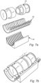
- FIG. 7a and 7b A further embodiment of the inset block according to the invention is illustrated in figure 7a and 7b .
- the insert half body is identical to as the previously described embodiment comprising recesses 41 in the groove.
- the inset 60 comprises fourteen different elements 61 to further increase the alternative radiuses the insert could be adapted to, and since the number of elements 61 exceed the number of recesses 41 in the groove the insert will extend outside the insert block.
- the design of the insert plug 20 and the position within the insert block halves is identical to the previously described embodiments, i.e. the flanges of the insert plug are located close to the end surfaces of the insert half bodies between adjacent elements of the insert.
- the embodiments described above could all be combined and modified in different ways without departing from the scope of the invention that is defined by the appended claims.
- the shape of the insert plug, the insert and the elements could be modified as long as the insert plug, the inserts and recesses in the groove correspond to each other and provide the desired sealing of the cables, wires and pipes extending through the frame in the partition wall.
Landscapes
- Engineering & Computer Science (AREA)
- General Engineering & Computer Science (AREA)
- Architecture (AREA)
- Civil Engineering (AREA)
- Structural Engineering (AREA)
- Mechanical Engineering (AREA)
- Physics & Mathematics (AREA)
- Electromagnetism (AREA)
- Installation Of Indoor Wiring (AREA)
- Laying Of Electric Cables Or Lines Outside (AREA)
Claims (13)
- Bloc d'insertion (4) destiné à assurer l'étanchéité autour d'un câble (2), d'un tuyau ou d'un fil, ledit bloc d'insertion comprenant :
deux moitiés d'insert (10) substantiellement identiques comprenant respectivement :un corps de moitié d'insert (11 ; 40) avec une première (12) et une deuxième extrémité (13), un premier côté (14), et une rainure (15) de forme semi-circulaire agencée dans ledit premier côté et s'étendant entre les première et deuxième extrémités le long d'un axe A, dans lequel les moitiés d'insert sont destinées à être agencées avec des premiers côtés adjacents l'un à l'autre de manière à former un passage substantiellement circulaire à travers le bloc d'insertion ; etun bouchon d'insert (20) agencé dans le passage substantiellement circulaire pour étanchéifier le passage, ledit bouchon d'insert comprenant au moins une section (27) le long de l'axe A, laquelle présente une section transversale circulaire avec un rayon correspondant au rayon du passage,caractérisé en ce queledit bouchon d'insert comprend au moins deux éléments de bouchon (21, 22) reliés de façon mobile l'un à l'autre de telle façon que la longueur du bouchon d'insert le long de l'axe A est réglable. - Bloc d'insertion selon la revendication 1, dans lequel le bouchon d'insert présente une longueur le long de l'axe A, laquelle est réglable dans la plage allant substantiellement égale à la distance entre les première et deuxième extrémités des moitiés de bloc d'insertion à une longueur dépassant la distance entre les première et deuxième extrémités des moitiés de bloc d'insertion.
- Bloc d'insertion selon la revendication 1 ou 2, dans lequel les corps de bloc d'insertion sont constitués d'une matière élastique et les au moins deux éléments de bouchon d'insert sont constitués d'une matière moins élastique que les corps de bloc d'insertion.
- Bloc d'insertion selon l'une quelconque des revendications précédentes, dans lequel les au moins deux éléments de bouchon d'insert sont constitués d'une matière non élastique.
- Bloc d'insertion selon l'une quelconque des revendications précédentes, dans lequel les au moins deux éléments de bouchon d'insert sont raccordés par une configuration mâle/femelle de telle sorte que la longueur le long de l'axe A est réglable, et ladite section du bouchon présentant une section transversale circulaire avec un rayon correspondant au rayon du passage s'étend à travers les au moins deux éléments de bouchon d'insert.
- Bloc d'insertion selon l'une quelconque des revendications précédentes, dans lequel le bouchon d'insert présente une première extrémité et une deuxième extrémité et comprend un premier rebord (30) agencé dans la première extrémité et s'étendant dans une direction radiale à partir de l'axe A et un deuxième rebord (30) agencé dans la deuxième extrémité et s'étendant dans une direction radiale à partir de l'axe A, lesdits rebords présentant un rayon dépassant le rayon du passage circulaire formé dans le bloc d'insertion de telle façon que les premier et deuxième rebords s'appuient contre les première et deuxième surfaces d'extrémité des moitiés d'insert.
- Bloc d'insertion selon la revendication 1, dans lequel un nombre de cavités (41) substantiellement identiques s'étendant substantiellement transversalement à l'axe A sont formées dans la rainure dans les deux moitiés d'insert, et chacune desdites moitiés d'insert comprend en outre au moins un insert (44 ; 50 ; 60) agencé de façon amovible dans ladite rainure, ledit insert est formé par au moins deux éléments (45) collés l'un à l'aitre côte à côte et s'étendant substantiellement transversalement à l'axe A, dans lequel lesdits inserts présentent une forme extérieure correspondant à la forme de la rainure et des cavités de sorte que l'insert (44 ; 50 ; 60) pourrait être agencé à n'importe quel endroit le long de la rainure, dans lequel chaque élément comprend une surface intérieure semi-circulaire avec un rayon différent de sorte qu'un passage avec différents rayons coaxial à l'axe A est formé de manière à adapter les rayons du passage à travers ledit bloc d'insertion, et le bouchon d'insert est agencé de manière à étanchéifier le passage formé par l'au moins un insert dans chaque moitié de bloc d'insertion.
- Bloc d'insertion selon la revendication 7, dans lequel la largeur des cavités le long de l'axe A correspond à la largeur d'un élément de sorte qu'un élément s'ajuste dans une cavité.
- Bloc d'insertion selon la revendication 7 ou 8, dans lequel l'insert (44) comprend le même nombre d'éléments que le nombre de cavités dans les moitiés d'insert.
- Bloc d'insertion selon la revendication 7 ou 8, dans lequel le bloc d'insertion comprend deux inserts (50) dans chaque moitié d'insert, un insert est agencé de façon adjacente à la première extrémité de la moitié d'insert et l'autre insert est agencé de façon adjacente à la deuxième extrémité du bloc d'insertion, et la section du bouchon présentant une section transversale circulaire avec un rayon correspondant au rayon du passage est agencée entre les deux inserts.
- Bloc d'insertion selon l'une quelconque des revendications 7 à 10, dans lequel le bouchon d'insert (20) présente une première extrémité et une deuxième extrémité et comprend un premier rebord (30) agencé dans la première extrémité et s'étendant dans une direction radiale à partir de l'axe A et un deuxième rebord (30) agencé dans la deuxième extrémité et s'étendant dans une direction radiale à partir de l'axe A, lesdits rebords présentant un rayon correspondant au rayon du passage circulaire formé par l'au moins un insert ou un rayon correspondant au rayon des cavités formées dans la rainure de sorte que le passage à travers l'insert est étanchéifié par le bouchon d'insert.
- Bloc d'insertion selon la revendication 11, dans lequel la longueur du bouchon d'insert le long de l'axe A est réglable de telle façon que le premier et/ou le deuxième rebord s'ajuste(-nt) dans les cavités adjacentes aux première et deuxième extrémités des moitiés de bloc d'insertion ou entre des éléments adjacents de l'au moins un insert agencés dans la rainure des moitiés d'insert.
- Système d'étanchéité (1) comprenant :un cadre (3) agencé dans une paroi de séparation ;au moins un bloc d'insertion (4) selon la revendication 1 agencé dans le cadre ;et un dispositif d'application de pression agencé dans le cadre pour appliquer une pression sur l'au moins un bloc d'insertion afin d'étanchéifier l'espace dans le cadre.
Applications Claiming Priority (2)
| Application Number | Priority Date | Filing Date | Title |
|---|---|---|---|
| SE1751645A SE541547C2 (en) | 2017-12-22 | 2017-12-22 | Insert block and sealing system comprising said insert block |
| PCT/SE2018/051309 WO2019125285A1 (fr) | 2017-12-22 | 2018-12-13 | Bloc d'insertion et système d'étanchéité comprenant ledit bloc d'insertion |
Publications (4)
| Publication Number | Publication Date |
|---|---|
| EP3729577A1 EP3729577A1 (fr) | 2020-10-28 |
| EP3729577A4 EP3729577A4 (fr) | 2021-08-04 |
| EP3729577C0 EP3729577C0 (fr) | 2024-03-06 |
| EP3729577B1 true EP3729577B1 (fr) | 2024-03-06 |
Family
ID=66995031
Family Applications (1)
| Application Number | Title | Priority Date | Filing Date |
|---|---|---|---|
| EP18893281.8A Active EP3729577B1 (fr) | 2017-12-22 | 2018-12-13 | Bloc d'insertion et système d'étanchéité comprenant ledit bloc d'insertion |
Country Status (5)
| Country | Link |
|---|---|
| EP (1) | EP3729577B1 (fr) |
| KR (1) | KR102660917B1 (fr) |
| CN (1) | CN111527659B (fr) |
| SE (1) | SE541547C2 (fr) |
| WO (1) | WO2019125285A1 (fr) |
Families Citing this family (2)
| Publication number | Priority date | Publication date | Assignee | Title |
|---|---|---|---|---|
| SE544914C2 (en) * | 2021-07-16 | 2022-12-27 | Mct Brattberg Ab | Pressure test insert and frame |
| SE547352C2 (en) * | 2023-11-02 | 2025-07-08 | Roxtec Ab | A sealing module, a use thereof and a transit system comprising such a sealing module |
Family Cites Families (13)
| Publication number | Priority date | Publication date | Assignee | Title |
|---|---|---|---|---|
| JPH06180264A (ja) * | 1992-06-05 | 1994-06-28 | Hitachi Constr Mach Co Ltd | 導線引出し部の封止構造及びこの封止構造を有するプラグ |
| JP2960675B2 (ja) * | 1995-02-01 | 1999-10-12 | 野地テック株式会社 | 橋架用ケーブルボックス |
| US6062267A (en) * | 1999-04-01 | 2000-05-16 | Fleming; Karl | Telescopic conduit passage assembly |
| ATE440239T1 (de) * | 2006-08-25 | 2009-09-15 | Beele Eng Bv | System zum dynamischen abdichten zumindest eines kanals, durch den sich ein rohr oder ein kabel erstreckt |
| CN201038680Y (zh) * | 2007-01-29 | 2008-03-19 | 江苏东洲通信设备有限公司 | 线缆穿墙密封窗 |
| CN202580325U (zh) * | 2012-05-02 | 2012-12-05 | 成都中寰流体控制设备有限公司 | 电缆封堵装置 |
| US9698588B2 (en) * | 2013-05-03 | 2017-07-04 | Cooper Technology Company | Universal bushing |
| WO2015065256A1 (fr) * | 2013-10-31 | 2015-05-07 | Mct Brattberg Ab | Moitié de bloc d'insert |
| SE538128C2 (sv) * | 2014-10-07 | 2016-03-08 | Mct Brattberg Ab | Insert block half |
| CN205212362U (zh) * | 2015-12-11 | 2016-05-04 | 国网山东青岛市黄岛区供电公司 | 一种电缆入户穿墙套管 |
| CN205319642U (zh) * | 2016-01-28 | 2016-06-15 | 林嘉承 | 一种电缆沟高压电缆密封装置 |
| SE539578C2 (en) * | 2016-04-05 | 2017-10-17 | Mct Brattberg Ab | Insert half, and insert block comprising two of said insert halves |
| CN206225939U (zh) * | 2016-11-15 | 2017-06-06 | 王洪喜 | 组合式馈线窗 |
-
2017
- 2017-12-22 SE SE1751645A patent/SE541547C2/en unknown
-
2018
- 2018-12-13 KR KR1020207020959A patent/KR102660917B1/ko active Active
- 2018-12-13 EP EP18893281.8A patent/EP3729577B1/fr active Active
- 2018-12-13 CN CN201880082369.8A patent/CN111527659B/zh not_active Expired - Fee Related
- 2018-12-13 WO PCT/SE2018/051309 patent/WO2019125285A1/fr not_active Ceased
Also Published As
| Publication number | Publication date |
|---|---|
| EP3729577A1 (fr) | 2020-10-28 |
| KR102660917B1 (ko) | 2024-04-25 |
| EP3729577C0 (fr) | 2024-03-06 |
| KR20200118003A (ko) | 2020-10-14 |
| SE541547C2 (en) | 2019-10-29 |
| SE1751645A1 (en) | 2019-06-23 |
| WO2019125285A1 (fr) | 2019-06-27 |
| EP3729577A4 (fr) | 2021-08-04 |
| CN111527659A (zh) | 2020-08-11 |
| CN111527659B (zh) | 2021-12-21 |
Similar Documents
| Publication | Publication Date | Title |
|---|---|---|
| AU2017248150B2 (en) | Insert half, and insert block comprising two of said insert halves | |
| EP3007290B1 (fr) | Demi-bloc d'insertion | |
| US9765908B2 (en) | Eccentric part of a pipe or cable lead-through | |
| EP2386133B2 (fr) | Couche pour un demi-insert, et demi-insert | |
| US20160281884A1 (en) | Insert block half | |
| EP3729577B1 (fr) | Bloc d'insertion et système d'étanchéité comprenant ledit bloc d'insertion | |
| EP3660373A1 (fr) | Élément d'extension dans un système d'étanchéité | |
| SE1451473A1 (sv) | Fire stop | |
| CA3019460C (fr) | Moitie d'insert, et bloc d'insert comprenant deux desdites moities d'insert | |
| WO2008069716A1 (fr) | Demi-bloc d'insertion et système d'étanchéité comprenant ledit demi-bloc d'insertion |
Legal Events
| Date | Code | Title | Description |
|---|---|---|---|
| STAA | Information on the status of an ep patent application or granted ep patent |
Free format text: STATUS: THE INTERNATIONAL PUBLICATION HAS BEEN MADE |
|
| PUAI | Public reference made under article 153(3) epc to a published international application that has entered the european phase |
Free format text: ORIGINAL CODE: 0009012 |
|
| STAA | Information on the status of an ep patent application or granted ep patent |
Free format text: STATUS: REQUEST FOR EXAMINATION WAS MADE |
|
| 17P | Request for examination filed |
Effective date: 20200707 |
|
| AK | Designated contracting states |
Kind code of ref document: A1 Designated state(s): AL AT BE BG CH CY CZ DE DK EE ES FI FR GB GR HR HU IE IS IT LI LT LU LV MC MK MT NL NO PL PT RO RS SE SI SK SM TR |
|
| AX | Request for extension of the european patent |
Extension state: BA ME |
|
| DAV | Request for validation of the european patent (deleted) | ||
| DAX | Request for extension of the european patent (deleted) | ||
| A4 | Supplementary search report drawn up and despatched |
Effective date: 20210702 |
|
| RIC1 | Information provided on ipc code assigned before grant |
Ipc: H02G 3/22 20060101AFI20210628BHEP Ipc: F16L 5/02 20060101ALI20210628BHEP Ipc: F16L 5/10 20060101ALI20210628BHEP |
|
| STAA | Information on the status of an ep patent application or granted ep patent |
Free format text: STATUS: EXAMINATION IS IN PROGRESS |
|
| 17Q | First examination report despatched |
Effective date: 20221019 |
|
| GRAP | Despatch of communication of intention to grant a patent |
Free format text: ORIGINAL CODE: EPIDOSNIGR1 |
|
| STAA | Information on the status of an ep patent application or granted ep patent |
Free format text: STATUS: GRANT OF PATENT IS INTENDED |
|
| INTG | Intention to grant announced |
Effective date: 20231020 |
|
| GRAS | Grant fee paid |
Free format text: ORIGINAL CODE: EPIDOSNIGR3 |
|
| GRAA | (expected) grant |
Free format text: ORIGINAL CODE: 0009210 |
|
| STAA | Information on the status of an ep patent application or granted ep patent |
Free format text: STATUS: THE PATENT HAS BEEN GRANTED |
|
| AK | Designated contracting states |
Kind code of ref document: B1 Designated state(s): AL AT BE BG CH CY CZ DE DK EE ES FI FR GB GR HR HU IE IS IT LI LT LU LV MC MK MT NL NO PL PT RO RS SE SI SK SM TR |
|
| REG | Reference to a national code |
Ref country code: GB Ref legal event code: FG4D |
|
| REG | Reference to a national code |
Ref country code: CH Ref legal event code: EP |
|
| REG | Reference to a national code |
Ref country code: IE Ref legal event code: FG4D |
|
| REG | Reference to a national code |
Ref country code: DE Ref legal event code: R096 Ref document number: 602018066397 Country of ref document: DE |
|
| U01 | Request for unitary effect filed |
Effective date: 20240306 |
|
| U07 | Unitary effect registered |
Designated state(s): AT BE BG DE DK EE FI FR IT LT LU LV MT NL PT SE SI Effective date: 20240313 |
|
| PG25 | Lapsed in a contracting state [announced via postgrant information from national office to epo] |
Ref country code: GR Free format text: LAPSE BECAUSE OF FAILURE TO SUBMIT A TRANSLATION OF THE DESCRIPTION OR TO PAY THE FEE WITHIN THE PRESCRIBED TIME-LIMIT Effective date: 20240607 |
|
| PG25 | Lapsed in a contracting state [announced via postgrant information from national office to epo] |
Ref country code: RS Free format text: LAPSE BECAUSE OF FAILURE TO SUBMIT A TRANSLATION OF THE DESCRIPTION OR TO PAY THE FEE WITHIN THE PRESCRIBED TIME-LIMIT Effective date: 20240606 Ref country code: HR Free format text: LAPSE BECAUSE OF FAILURE TO SUBMIT A TRANSLATION OF THE DESCRIPTION OR TO PAY THE FEE WITHIN THE PRESCRIBED TIME-LIMIT Effective date: 20240306 |
|
| PG25 | Lapsed in a contracting state [announced via postgrant information from national office to epo] |
Ref country code: ES Free format text: LAPSE BECAUSE OF FAILURE TO SUBMIT A TRANSLATION OF THE DESCRIPTION OR TO PAY THE FEE WITHIN THE PRESCRIBED TIME-LIMIT Effective date: 20240306 |
|
| PG25 | Lapsed in a contracting state [announced via postgrant information from national office to epo] |
Ref country code: RS Free format text: LAPSE BECAUSE OF FAILURE TO SUBMIT A TRANSLATION OF THE DESCRIPTION OR TO PAY THE FEE WITHIN THE PRESCRIBED TIME-LIMIT Effective date: 20240606 Ref country code: HR Free format text: LAPSE BECAUSE OF FAILURE TO SUBMIT A TRANSLATION OF THE DESCRIPTION OR TO PAY THE FEE WITHIN THE PRESCRIBED TIME-LIMIT Effective date: 20240306 Ref country code: GR Free format text: LAPSE BECAUSE OF FAILURE TO SUBMIT A TRANSLATION OF THE DESCRIPTION OR TO PAY THE FEE WITHIN THE PRESCRIBED TIME-LIMIT Effective date: 20240607 Ref country code: ES Free format text: LAPSE BECAUSE OF FAILURE TO SUBMIT A TRANSLATION OF THE DESCRIPTION OR TO PAY THE FEE WITHIN THE PRESCRIBED TIME-LIMIT Effective date: 20240306 |
|
| PG25 | Lapsed in a contracting state [announced via postgrant information from national office to epo] |
Ref country code: IS Free format text: LAPSE BECAUSE OF FAILURE TO SUBMIT A TRANSLATION OF THE DESCRIPTION OR TO PAY THE FEE WITHIN THE PRESCRIBED TIME-LIMIT Effective date: 20240706 |
|
| PG25 | Lapsed in a contracting state [announced via postgrant information from national office to epo] |
Ref country code: SM Free format text: LAPSE BECAUSE OF FAILURE TO SUBMIT A TRANSLATION OF THE DESCRIPTION OR TO PAY THE FEE WITHIN THE PRESCRIBED TIME-LIMIT Effective date: 20240306 |
|
| PG25 | Lapsed in a contracting state [announced via postgrant information from national office to epo] |
Ref country code: CZ Free format text: LAPSE BECAUSE OF FAILURE TO SUBMIT A TRANSLATION OF THE DESCRIPTION OR TO PAY THE FEE WITHIN THE PRESCRIBED TIME-LIMIT Effective date: 20240306 |
|
| PG25 | Lapsed in a contracting state [announced via postgrant information from national office to epo] |
Ref country code: PL Free format text: LAPSE BECAUSE OF FAILURE TO SUBMIT A TRANSLATION OF THE DESCRIPTION OR TO PAY THE FEE WITHIN THE PRESCRIBED TIME-LIMIT Effective date: 20240306 |
|
| PG25 | Lapsed in a contracting state [announced via postgrant information from national office to epo] |
Ref country code: SK Free format text: LAPSE BECAUSE OF FAILURE TO SUBMIT A TRANSLATION OF THE DESCRIPTION OR TO PAY THE FEE WITHIN THE PRESCRIBED TIME-LIMIT Effective date: 20240306 |
|
| PG25 | Lapsed in a contracting state [announced via postgrant information from national office to epo] |
Ref country code: SM Free format text: LAPSE BECAUSE OF FAILURE TO SUBMIT A TRANSLATION OF THE DESCRIPTION OR TO PAY THE FEE WITHIN THE PRESCRIBED TIME-LIMIT Effective date: 20240306 Ref country code: SK Free format text: LAPSE BECAUSE OF FAILURE TO SUBMIT A TRANSLATION OF THE DESCRIPTION OR TO PAY THE FEE WITHIN THE PRESCRIBED TIME-LIMIT Effective date: 20240306 Ref country code: RO Free format text: LAPSE BECAUSE OF FAILURE TO SUBMIT A TRANSLATION OF THE DESCRIPTION OR TO PAY THE FEE WITHIN THE PRESCRIBED TIME-LIMIT Effective date: 20240306 Ref country code: PL Free format text: LAPSE BECAUSE OF FAILURE TO SUBMIT A TRANSLATION OF THE DESCRIPTION OR TO PAY THE FEE WITHIN THE PRESCRIBED TIME-LIMIT Effective date: 20240306 Ref country code: IS Free format text: LAPSE BECAUSE OF FAILURE TO SUBMIT A TRANSLATION OF THE DESCRIPTION OR TO PAY THE FEE WITHIN THE PRESCRIBED TIME-LIMIT Effective date: 20240706 Ref country code: CZ Free format text: LAPSE BECAUSE OF FAILURE TO SUBMIT A TRANSLATION OF THE DESCRIPTION OR TO PAY THE FEE WITHIN THE PRESCRIBED TIME-LIMIT Effective date: 20240306 |
|
| REG | Reference to a national code |
Ref country code: DE Ref legal event code: R097 Ref document number: 602018066397 Country of ref document: DE |
|
| U20 | Renewal fee for the european patent with unitary effect paid |
Year of fee payment: 7 Effective date: 20241114 |
|
| PLBE | No opposition filed within time limit |
Free format text: ORIGINAL CODE: 0009261 |
|
| STAA | Information on the status of an ep patent application or granted ep patent |
Free format text: STATUS: NO OPPOSITION FILED WITHIN TIME LIMIT |
|
| 26N | No opposition filed |
Effective date: 20241209 |
|
| PG25 | Lapsed in a contracting state [announced via postgrant information from national office to epo] |
Ref country code: MC Free format text: LAPSE BECAUSE OF FAILURE TO SUBMIT A TRANSLATION OF THE DESCRIPTION OR TO PAY THE FEE WITHIN THE PRESCRIBED TIME-LIMIT Effective date: 20240306 |
|
| REG | Reference to a national code |
Ref country code: CH Ref legal event code: PL |
|
| PG25 | Lapsed in a contracting state [announced via postgrant information from national office to epo] |
Ref country code: CH Free format text: LAPSE BECAUSE OF NON-PAYMENT OF DUE FEES Effective date: 20241231 |
|
| PG25 | Lapsed in a contracting state [announced via postgrant information from national office to epo] |
Ref country code: IE Free format text: LAPSE BECAUSE OF NON-PAYMENT OF DUE FEES Effective date: 20241213 |
|
| U20 | Renewal fee for the european patent with unitary effect paid |
Year of fee payment: 8 Effective date: 20251027 |
|
| PGFP | Annual fee paid to national office [announced via postgrant information from national office to epo] |
Ref country code: GB Payment date: 20251027 Year of fee payment: 8 |
|
| PGFP | Annual fee paid to national office [announced via postgrant information from national office to epo] |
Ref country code: NO Payment date: 20251029 Year of fee payment: 8 |