EP3730263A1 - Verfahren zur herstellung einer vielzahl von betongusselementen aus spannbeton - Google Patents
Verfahren zur herstellung einer vielzahl von betongusselementen aus spannbeton Download PDFInfo
- Publication number
- EP3730263A1 EP3730263A1 EP19450007.0A EP19450007A EP3730263A1 EP 3730263 A1 EP3730263 A1 EP 3730263A1 EP 19450007 A EP19450007 A EP 19450007A EP 3730263 A1 EP3730263 A1 EP 3730263A1
- Authority
- EP
- European Patent Office
- Prior art keywords
- elements
- concrete
- tensioning
- clamping
- separating
- Prior art date
- Legal status (The legal status is an assumption and is not a legal conclusion. Google has not performed a legal analysis and makes no representation as to the accuracy of the status listed.)
- Granted
Links
Images



Classifications
-
- B—PERFORMING OPERATIONS; TRANSPORTING
- B28—WORKING CEMENT, CLAY, OR STONE
- B28B—SHAPING CLAY OR OTHER CERAMIC COMPOSITIONS; SHAPING SLAG; SHAPING MIXTURES CONTAINING CEMENTITIOUS MATERIAL, e.g. PLASTER
- B28B23/00—Arrangements specially adapted for the production of shaped articles with elements wholly or partly embedded in the moulding material; Production of reinforced objects
- B28B23/02—Arrangements specially adapted for the production of shaped articles with elements wholly or partly embedded in the moulding material; Production of reinforced objects wherein the elements are reinforcing members
- B28B23/04—Arrangements specially adapted for the production of shaped articles with elements wholly or partly embedded in the moulding material; Production of reinforced objects wherein the elements are reinforcing members the elements being stressed
- B28B23/043—Wire anchoring or tensioning means for the reinforcements
-
- B—PERFORMING OPERATIONS; TRANSPORTING
- B28—WORKING CEMENT, CLAY, OR STONE
- B28B—SHAPING CLAY OR OTHER CERAMIC COMPOSITIONS; SHAPING SLAG; SHAPING MIXTURES CONTAINING CEMENTITIOUS MATERIAL, e.g. PLASTER
- B28B23/00—Arrangements specially adapted for the production of shaped articles with elements wholly or partly embedded in the moulding material; Production of reinforced objects
- B28B23/02—Arrangements specially adapted for the production of shaped articles with elements wholly or partly embedded in the moulding material; Production of reinforced objects wherein the elements are reinforcing members
- B28B23/022—Means for inserting reinforcing members into the mould or for supporting them in the mould
- B28B23/024—Supporting means
- B28B23/026—Mould partitionning elements acting as supporting means in moulds, e.g. for elongated articles
-
- B—PERFORMING OPERATIONS; TRANSPORTING
- B28—WORKING CEMENT, CLAY, OR STONE
- B28B—SHAPING CLAY OR OTHER CERAMIC COMPOSITIONS; SHAPING SLAG; SHAPING MIXTURES CONTAINING CEMENTITIOUS MATERIAL, e.g. PLASTER
- B28B23/00—Arrangements specially adapted for the production of shaped articles with elements wholly or partly embedded in the moulding material; Production of reinforced objects
- B28B23/02—Arrangements specially adapted for the production of shaped articles with elements wholly or partly embedded in the moulding material; Production of reinforced objects wherein the elements are reinforcing members
- B28B23/04—Arrangements specially adapted for the production of shaped articles with elements wholly or partly embedded in the moulding material; Production of reinforced objects wherein the elements are reinforcing members the elements being stressed
- B28B23/046—Post treatment to obtain pre-stressed articles
-
- B—PERFORMING OPERATIONS; TRANSPORTING
- B28—WORKING CEMENT, CLAY, OR STONE
- B28B—SHAPING CLAY OR OTHER CERAMIC COMPOSITIONS; SHAPING SLAG; SHAPING MIXTURES CONTAINING CEMENTITIOUS MATERIAL, e.g. PLASTER
- B28B23/00—Arrangements specially adapted for the production of shaped articles with elements wholly or partly embedded in the moulding material; Production of reinforced objects
- B28B23/02—Arrangements specially adapted for the production of shaped articles with elements wholly or partly embedded in the moulding material; Production of reinforced objects wherein the elements are reinforcing members
- B28B23/04—Arrangements specially adapted for the production of shaped articles with elements wholly or partly embedded in the moulding material; Production of reinforced objects wherein the elements are reinforcing members the elements being stressed
- B28B23/06—Arrangements specially adapted for the production of shaped articles with elements wholly or partly embedded in the moulding material; Production of reinforced objects wherein the elements are reinforcing members the elements being stressed for the production of elongated articles
Definitions
- the present invention relates to a method for producing a large number of concrete cast elements from prestressed concrete, in particular for the production of railway sleepers, in a long bed which is a multiple of the length of a concrete cast element, in which separating elements are used in the long bed to define the length of the concrete cast elements to be poured, as well as a device for carrying out the method according to the invention.
- the tensioning elements or tensioning wires have suitable surface structures or a significant roughness in order to achieve sufficient adhesion of the concrete element so that the desired prestressing can be applied.
- the pre-tensioning is released and the tensioning elements or tensioning wires transmit a corresponding tension to the concrete body, for example to the railroad tie, via the direct bond with the concrete.
- end bracing the tensioning force being applied to the cast concrete element or the railway sleeper by tensioning the tension wire only after the concrete has hardened.
- the tensioning element or tensioning wire must not have any appreciable adhesion to the concrete of the cast part, since the tensioning force should only act on suitable anchors.
- a major advantage of the end anchoring is that the pre-tensioning is constant over the entire sleeper body and thus the susceptibility to cracking in the event of stress can also be significantly reduced in the end area of the concrete sleeper.
- support plates or separating elements are placed in long beds according to the desired concrete sleeper length, the length of the long bed being a multiple of the length of a concrete casting element (approx. 100 m).
- the tensioning wires are pulled through the separating elements over the entire length of the long bed and tensioned using a separate tensioning frame or using foundations with appropriate abutments. Then the concrete is poured.
- a single Sleeper body manufactured in its own molding box which, in the case of the production of end-tensioned railway sleepers, contains a tensioning device that allows the tensioning wires to be tensioned after the concrete has hardened and is supported against the molding box before the concrete is poured. Then the concrete is poured in.
- a concrete sleeper with prestressing can be produced using the carousel method.
- prestressed and end-braced railway sleepers can again be produced in molding boxes. It would therefore be desirable to be able to manufacture pre-tensioned and end-tensioned railway sleepers in existing long beds.
- the present invention is therefore based on the object of producing stable, pre-tensioned and end-tensioned railway sleepers in a long bed.
- the method of the type mentioned at the beginning is characterized according to the invention in that a first and a second separating element for defining the length of a concrete casting element are fixed together with a clamping device with clamping elements between the two separating elements in the long bed, whereupon the concrete casting element is poured between the two separating elements and is at least partially cured in the long bed.
- each concrete casting to be cast or each railway sleeper to be cast has two separate separating elements associated with it in order to define the length of the concrete casting. Furthermore, a separate clamping device is arranged in each of the areas delimited by the two separating elements, with which the respective cast part can be clamped, the clamping elements being able to be clamped before the concrete is poured or only after the concrete has hardened. In this way, a large number of railway sleepers can be produced in a long bed in one casting process.
- the separating elements with the clamping devices for a Prepare the next batch outside of the long bed so that when the long bed is free, they only have to be inserted and fixed in order to continue pouring the concrete immediately.
- the preparation of the tensioning device usually includes attaching the tensioning elements to a first abutment to be cast and, in the event of final tensioning, sheathing the tension wires with a shuttering sleeve, which generally includes passing the wires through suitable hoses and threading a second abutment so that it becomes clear that it represents a considerable time saving if these steps can be carried out outside of the long bed, while the long bed is anyway, for example, occupied by hardening concrete masses.
- the carousel process has to wait until the molding boxes are free again after the concrete has hardened and the concrete cast parts have been removed in order to be able to use the Equipping the molding boxes with the jigs to be able to begin.
- pre-tensioned or end-tensioned railway sleepers can thus be produced economically in existing long-bed systems with a high throughput rate, the long bed being able to be filled with concrete almost continuously, since the preparation of the tensioning devices and the separating elements already takes place during the hardening process the concrete can take place outside the long bed.
- the procedure is preferably such that the concrete casting element is braced after the concrete has partially hardened while the tensioning elements are tensioned.
- end-tensioned concrete cast parts or railway sleepers can now also be produced in the long bed, so that the advantages associated with end-tensioned railway sleepers can also be achieved in existing long-bed systems.
- the procedure is such that the separating elements are fixed by means of screw connections on a transverse plate supported on side elements of the long bed.
- the separating elements have an L-shaped cross section, optionally with reinforcing ribs, in order to screw the separating elements into corresponding threads of the transverse plates.
- the transverse sheets are held on the two side elements below the long bed and screwed to the separating elements. This creates a firm connection between the separating elements and the long bed without the long bed itself having to be structurally redesigned must become.
- the clamping elements can be designed in various ways. In the context of the present invention, however, it is preferred for the production of end-tensioned concrete cast elements that the tensioning elements are designed as tensioning wires, the tensioning elements being guided in formwork sleeves in the area between the abutments.
- the tension wires are cut to the appropriate length and inserted into the formwork sleeves, usually simple plastic hoses.
- the formwork sleeves prevent direct contact and bonding with the later poured concrete so that the tensioning elements can be brought to the required tension through the entire length of the concrete casting after the concrete has hardened and the concrete casting is consequently clamped together from the ends.
- the tensioning elements or tensioning wires can be suitably held in various ways between the separating elements in the long bed. According to a preferred embodiment of the present invention, however, it is provided that the clamping elements are supported at their first end on an abutment designed as a fixed anchor element, which is preferably connected to the first separating element by means of at least one clamping screw, in particular releasably connected. Because the tension wires are fixed to a fixed anchor element, the tension wires are firmly anchored in the concrete after the concrete has been poured and hardened and can apply great tension forces to the concrete casting in order to brace it.
- a tensioning element or a tensioning wire can be fixed to a fixed anchor element, but it can also be provided that several tensioning elements, for example two Clamping elements are set on a common fixed anchor element.
- the fixed anchor element is preferably designed as an anchor plate with a corresponding number of holes for receiving the clamping elements, the clamping elements being fixed to the fixed anchor element by suitable means.
- screw nuts, clamps or the like are particularly suitable, but the clamping elements can also be caulked on the rear of the fixed anchor elements.
- the fixed anchor elements are in turn fixed to the first separating element with appropriate spacers, for example by means of clamping screws.
- the final tensioning of the tensioning elements after the concrete has hardened is preferably carried out with the aid of tensioning nuts, which each interact with a corresponding thread on the second end of the tensioning elements.
- the tensioning nuts are supported on a tensioning anchor element in the cast concrete part, so that when the tensioning nuts are tightened, a tensile force is exerted on the tensioning elements or tensioning wires and the concrete is clamped together.
- the method according to the invention is preferably further developed in that the clamping elements are each connected, in particular screwed, to a clamping sleeve at their second end, which is supported on the second separating element.
- the clamping sleeves are removed after the concrete casting element has been poured and after the concrete has hardened, so that there are open recesses in the concrete casting part, which then enable access to the second ends of the clamping elements in order to be able to attach and tighten the clamping nuts.
- the method according to the invention can preferably be developed in such a way that at least one abutment designed as a tensioning anchor element is cast into the concrete casting element to support tensioning nuts in the cast concrete part.
- the at least one tensioning anchor element is preferably designed as an anchor plate with a plurality of holes for the tensioning elements to pass through.
- a preferred procedure provides that the tensioning elements are partially tensioned prior to the pouring of the concrete casting element, the tensioning force preferably being less than 10 kN per tensioning element. A low tensioning force is thus applied, which is just sufficient to bring the tensioning elements into a straight position, the tensioning preferably being carried out by pulling at least one end of the tensioning elements towards the respective separating element after the separating elements have been fixed in the long bed. It is preferably provided here that the first ends of the tensioning elements are held on the first separating element via the at least one fixed anchor element and the at least one tensioning screw, while the second ends of the tensioning elements are pulled to the second separating element by means of the clamping sleeves. As already mentioned, the clamping sleeves are preferably screwed to the second ends of the clamping elements so that the required clamping force can be applied by rotating the clamping sleeves.
- the method according to the invention can be used to produce prestressed concrete cast elements be developed in such a way that the tensioning elements are tensioned before the concrete casting elements are poured.
- the tensioning elements are designed without formwork sleeves and, if necessary, with a corresponding surface structure, in order to produce the tightest and most direct possible connection between the tensioning elements or the tensioning wires and the concrete.
- This procedure for the production of pre-tensioned concrete cast elements in the long bed has the advantage over the already known method for the production of pre-tensioned concrete cast elements in the long bed that the separating elements can be prepared with the clamping devices for a subsequent batch outside the long bed, so that they only have to be released when the long bed is free must be used and set in order to proceed with pouring the concrete immediately.
- a preferred embodiment provides that the separating elements are removed after initial hardening but before the final strength of the concrete has been reached, the tensioning elements are partially tensioned, the concrete casting element is removed from the long bed and the tensioning elements are then finally tensioned. Because the tensioning elements are partially tensioned after an initial hardening, the concrete casting element can be given the stability required for removal from the long bed after a short hardening time, so that removal can take place after an extremely short time. In particular, the concrete casting element can be removed from the long bed as early as 16-48 hours after casting. After removal, further hardening takes place outside the long bed, with the final bracing of the concrete cast element taking place after a specified target strength has been reached.
- the clamping elements are preferably partially clamped to a clamping force of 20-50 kN per clamping element.
- the device according to the invention for producing a plurality of concrete cast elements from prestressed concrete, in particular for the production of railway sleepers, in a long bed having a multiple of the length of a concrete casting element is characterized according to the invention in that it has a first and a second separating element with means for fixing the separating elements in the long bed and a clamping device with clamping elements, which is arranged between the two separating elements.
- the device according to the invention can thus in a long bed, ie in an elongated casting mold, the length of which exceeds the length of a conventional railway sleeper many times over and in particular has a length of approx.
- each concrete casting to be cast or each railway sleeper to be cast can be arranged and set to define the length of the concrete casting.
- the tensioning device between the two separating elements the casting can be put under tension before or after the at least partial hardening of the concrete.
- a large number of devices according to the invention in a long bed a large number of railway sleepers can be produced in one casting process.
- the clamping devices according to the invention can already be prepared outside of the long bed while the concrete in the long bed is still hardening from the previous casting process, so that when the long bed is free, they only need to be inserted and fixed in order to continue pouring the concrete immediately.
- the preparation or upgrading of the tensioning device usually includes attaching the tensioning elements to an abutment to be cast, if necessary encasing the tensioning elements with a formwork sleeve, which generally includes passing the tensioning elements through suitable hoses, and applying a second abutment so that it becomes clear that it represents a significant time saving if these steps can be carried out when the long bed is already occupied, for example by hardening concrete masses.
- end-braced railway sleepers can thus be produced economically in already existing long-bed systems with a high throughput rate, the long bed being able to be filled with concrete almost continuously, since the preparation of the separating elements and clamping devices already takes place during the hardening of the concrete outside the Long bed can be made.
- the means for fixing the separating elements each comprise at least one screw for screwing into a corresponding thread of a transverse plate supported on side elements of the long bed.
- the separating elements have an L-shaped cross-section, optionally with reinforcing ribs, in order to screw the separating elements to the transverse plates.
- the tensioning elements are preferably designed as tension wires. Furthermore, the tensioning elements in the area between the separating elements for the production of end tensioned railway sleepers are preferably guided in formwork sleeves.
- the clamping elements are cut to the appropriate length and inserted into the formwork sleeves, usually simple plastic tubes.
- the formwork sleeves prevent direct contact and bonding with the later poured concrete, so that the tensioning elements can be brought to the required tension through the entire length of the concrete casting after the concrete has hardened.
- the inventive device is further developed in that the clamping elements are supported at their first end on at least one abutment designed as a fixed anchor element, which is preferably connected, preferably releasably connected, to the first separating element by means of at least one clamping screw.
- the fixed anchor element is preferably designed as an anchor plate which has a plurality of holes for the passage of clamping elements.
- the at least one fixed anchor element can be attached to the first separating element with the help of at least one clamping screw, the clamping screw preferably being releasably connectable to the fixed anchor element so that the clamping screw can be removed and reused after the concrete has hardened.
- a clamping sleeve is connected, in particular screwed, to the second end of a clamping element and is supported on the second separating element.
- the clamping sleeve is used to fasten the second end of the respective clamping element to the second separating element and, if desired, to exert a slight pre-tension on the clamping elements in order to prevent the clamping elements from sagging before casting.
- the device according to the invention is preferably developed in such a way that the clamping sleeves are designed to provide a recess for attaching clamping nuts to the second end of the clamping elements after removal from the mold to train.
- the device according to the invention can preferably be further developed to the effect that for support of clamping nuts in the cast concrete part, at least one abutment designed as a clamping anchor element is arranged in the region of the second separating element.
- a tensioning anchor element is preferably an anchor plate which is equipped with a corresponding number of holes for receiving the tensioning elements, the tensioning elements being provided with a thread at the second end onto which tensioning nuts are screwed and screwed against the anchor plate.
- the separating elements according to the invention can be removed from the long bed after the concrete has hardened by pulling the separating elements axially from the railway sleepers. From this point of view it is possible with the device according to the invention to provide separating elements with a profile which results in a desired shaping of the end regions of the railway sleepers when the concrete is poured and hardened. In this context, it is particularly preferred that at least one of the separating elements has a negative shape for an end structure, in particular an end bevel on the concrete casting.
- railway sleepers should not necessarily have a purely cuboid shape at the ends and, in particular, railway sleepers are usually produced with chamfers which, in the prior art, can only be produced after the concrete has hardened, for example by grinding or cutting the concrete casting.
- the invention provides two separating elements for each concrete casting element, that is to say that two concrete casting parts are not separated from one another by a single separating element, the separating elements can be axially removed or withdrawn from the concrete casting parts, so that more complex shapes can also be cast Demolding transverse to the longitudinal axis of the concrete casting would be impossible.
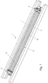
- a long bed is denoted by 1, where in Fig. 1 only a section of such a long bed 1 is shown.
- a first separating element 2 and a second separating element 3 are fixed to side elements 1 ′ of the long bed 1 by means of a screw connection.
- a clamping device 5 with clamping elements 6 is fixed between the two separating elements 2 and 3.
- a bottom plate 4 limits the long bed 1 downwards. Concrete can be poured into the casting space 7 in order to form a railway sleeper between the separating elements 2 and 3, into which the tensioning device 6 is cast.
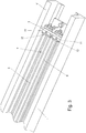
- Fig. 2 it can be seen that the clamping elements 6 under Interposition of first fixed anchor elements or anchor plates 8 and furthermore with the interposition of clamping screws 9 on the first separating element 2 are fixed.
- the anchor plates 8 form a strong abutment in the concrete in order to be able to exert tension forces on the concrete.
- Fig. 3 it is shown that the clamping elements 6 pass through clamping anchor elements or anchor plates 10 with their second end regions and are screwed to clamping sleeves 11 which are connected to the second separating element 3.
- the clamping sleeves 11 fix the second end of the clamping elements 6 during casting and, after they have been removed from the hardened concrete, simultaneously create a recess that enables a clamping nut 12 to be screwed onto the second ends of the clamping elements 6.
- a recess can now be seen in the example of one of the clamping elements, which was created after a clamping sleeve 11 was removed from the mold. Furthermore, a clamping nut 12 can be seen, which was screwed onto the second end of the clamping element 6. If the anchor plate 10 is now embedded in the concrete casting, tightening the clamping nut 12 leads to the tension wire 6, which is guided in a shuttering sleeve 13, being pulled in the direction of arrow 14 and thereby exerting a tension force on the concrete casting.
- Fig. 5 illustrates that the separating elements 2 or 3 can have a negative shape for an end structure such as, for example, a chamfer. This would not be possible if the separating elements of the present invention were not accessible on both sides, since such a structure cannot be demolded transversely to the axial direction.
- Fig. 6 shows that the long bed 1 has a length which exceeds the length of a concrete casting by a multiple and that therefore a plurality of devices according to the invention can be arranged in a long bed 1 and a large number of railway sleepers can be produced.
Landscapes
- Engineering & Computer Science (AREA)
- Manufacturing & Machinery (AREA)
- Chemical & Material Sciences (AREA)
- Ceramic Engineering (AREA)
- Mechanical Engineering (AREA)
- Manufacturing Of Tubular Articles Or Embedded Moulded Articles (AREA)
Abstract
Description
- Die vorliegende Erfindung betrifft ein Verfahren zur Herstellung einer Vielzahl von Betongusselementen aus Spannbeton, insbesondere zur Herstellung von Eisenbahnschwellen, in einem ein Vielfaches der Länge eines Betongusselements aufweisenden Langbett, bei welchem zur Längendefinition der zu gießenden Betongusselemente Trennelemente in das Langbett eingesetzt werden, sowie eine Vorrichtung zur Durchführung des erfindungsgemäßen Verfahrens.
- Auf dem Gebiet der Eisenbahnschwellen aus Spannbeton unterscheidet man zwei Verfahren zur Übertragung einer Spannkraft auf das Betongusselement.
- Zum Einen gibt es die Möglichkeit, einen direkten Verbund der Spannelemente bzw. der Spanndrähte mit dem Beton herzustellen, wobei eine Vorspannung auf eine Mehrzahl von Spannelementen zumeist in Form von Spanndrähten vor dem Gießen des Betons in ein entsprechend geformtes Formbett bzw. Spannbett aufgebracht wird. Die Spannelemente bzw. die Spanndrähte weisen hierbei zur Verbesserung der Haftung des Betons geeignete Oberflächenstrukturen bzw. eine deutliche Rauigkeit auf, um eine ausreichende Haftung des Betonelements zu erzielen, damit die gewünschte Vorspannung aufgebracht werden kann. Nach dem Aushärten des Betons wird die Vorspannung aufgehoben und die Spannelemente bzw. die Spanndrähte übertragen über den direkten Verbund mit dem Beton eine entsprechende Spannung auf den Betonkörper bspw. auf die Eisenbahnschwelle. Eine Übertragung der vollen Vorspannkraft ist bei der dergestalt vorgespannten ≈ Eisenbahnschwelle abhängig von der Betongüte und der Profilierung des Spanndrahtes, jedenfalls jedoch erst in einem deutlichen Abstand von den Stirnseiten der Betonschwelle wirksam. Daraus ergibt sich als Nachteil, dass die Endbereiche derart hergestellter Eisenbahnschwellen eine verminderte Festigkeit aufweisen und damit einhergehend zu vermehrter Rissbildung neigen. Die zulässige Liegezeit solcher Eisenbahnschwellen ist daher relativ begrenzt.
- Ein anderes Konzept ist als Endverspannung bekannt, wobei die Spannkraft durch Spannen des Spanndrahtes erst nach dem Aushärten des Betons auf das Betongusselement bzw. die Eisenbahnschwelle aufgebracht wird. Hierzu darf das Spannelement bzw. der Spanndraht im Gegensatz zum Konzept der Vorspannung keine nennenswerte Haftung mit dem Beton des Gussteils aufweisen, da die Spannkraft lediglich auf geeignete Anker wirken soll.
- Ein wesentlicher Vorteil der Endverankerung besteht darin, dass die Vorspannung über den gesamten Schwellenkörper konstant ist und damit die Rissanfälligkeit bei Beanspruchung auch im Endbereich der Betonschwelle deutlich reduziert werden kann.
- Als Fertigungsverfahren sind einerseits das Langbettverfahren für vorgespannte Eisenbahnschwellen und andererseits das Karussellverfahren vor allem für die Herstellung von endverspannten Betonschwellen bekannt.
- Beim Langbettverfahren werden Stützbleche bzw. Trennelemente entsprechend der gewünschten Betonschwellenlänge in Langbetten eingebracht, wobei die Länge des Langbetts ein Vielfaches der Länge eines Betongusselements aufweist (ca. 100m). Über die gesamte Länge des Langbetts werden die Spanndrähte durch die Trennelemente gezogen und mittels eines gesonderten Spannrahmens oder mit Hilfe von Fundamenten mit entsprechenden Widerlagern gespannt. Danach erfolgt das Gießen des Betons.
- Im Karussellverfahren wird jeweils ein einzelner Schwellenkörper in einem eigenen Formkasten hergestellt, der im Falle der Herstellung von endverspannten Eisenbahnschwellen eine Spannvorrichtung beinhaltet, die das Spannen der Spanndrähte nach dem Aushärten des Betons erlaubt und vor dem Gießen des Betons gegen den Formkasten abgestützt ist. Danach wird der Beton eingefüllt. Alternativ kann im Karussellverfahren auch eine Betonschwelle mit Vorspannung hergestellt werden.
- Während im Langbettverfahren bisher nur vorgespannte Betonteile hergestellt werden können, die mit den genannten Nachteilen behaftet sind, können in Formkästen wiederum vorgespannte und endverspannte Eisenbahnschwellen hergestellt werden. Es wäre daher wünschenswert, vorgespannte und endverspannte Eisenbahnschwellen auch in bereits bestehenden Langbetten herstellen zu können.
- Der vorliegenden Erfindung liegt daher die Aufgabe zugrunde, stabile vorgespannte und endverspannte Eisenbahnschwellen im Langbett herzustellen.
- Zur Lösung dieser Aufgabe ist das Verfahren der eingangs genannten Art erfindungsgemäß dadurch gekennzeichnet, dass jeweils ein erstes und ein zweites Trennelement zur Längendefinition eines Betongusselements zusammen mit einer Spannvorrichtung mit Spannelementen zwischen den beiden Trennelementen im Langbett festgelegt werden, woraufhin das Betongusselement zwischen den beiden Trennelementen gegossen und im Langbett zumindest teilweise ausgehärtet wird.
- Bei dem erfindungsgemäßen Verfahren werden somit in einem Langbett, d.h. einer Gussform, deren Länge die Länge einer üblichen Eisenbahnschwelle um eine Vielfaches übersteigt und insbesondere eine Länge von 100 Metern und mehr aufweist, jedem zu gießenden Betongussteil bzw. jeder zu gießenden Eisenbahnschwelle zwei eigene Trennelemente zugeordnet, um die Länge des Betongussteils zu definieren. Weiters wird in jedem der derart durch die zwei Trennelemente begrenzten Bereiche eine eigene Spannvorrichtung angeordnet, mit der das jeweilige Gussteil gespannt werden kann, wobei das Verspannen der Spannelemente bereits vor dem Gießen des Betons oder erst nach dem Aushärten des Betons erfolgen kann. Auf diese Weise kann eine Vielzahl von Eisenbahnschwellen im Langbett in einem Gussvorgang hergestellt werden. Darüberhinaus kann gegenüber dem Karussellverfahren mit Formkästen schon während das Langbett beim erfindungsgemäßen Verfahren noch durch die Trennelemente, die Spannvorrichtungen, gegebenenfalls den Beton und auch während des Aushärtens des Betons einer vorangehenden Charge belegt ist, bereits damit begonnen werden, die Trennelemente mit den Spannvorrichtungen für eine nachfolgende Charge außerhalb des Langbetts vorzubereiten, sodass diese bei Freiwerden des Langbetts nur noch eingesetzt und festgelegt werden müssen, um umgehend mit dem Gießen des Betons fortzufahren. Das Vorbereiten der Spannvorrichtung umfasst üblicherweise das Anbringen der Spannelemente an einem ersten einzugießenden Widerlager und im Falle einer Endverspannung das Umhüllen der Spanndrähte mit einer Schalungshülse, was im Allgemeinen das Durchführen der Drähte durch geeignete Schläuche beinhaltet und das Auffädeln eines zweiten Widerlagers, sodass klar wird, dass es eine erhebliche Zeitersparnis darstellt, wenn diese Schritte außerhalb des Langbetts vorgenommen werden können, während das Langbett ohnehin bspw. durch aushärtende Betonmassen belegt ist. Demgegenüber muss beim Karussellverfahren zugewartet werden, bis die Formkästen nach dem Aushärten des Betons und der Entnahme der Betongussteile wieder frei sind, um mit dem Ausrüsten der Formkästen mit den Spannvorrichtungen beginnen zu können.
- Mit dem erfindungsgemäßen Verfahren können somit auf ökonomische Weise in bereits bestehenden Langbett-Anlagen vor- oder endverspannte Eisenbahnschwellen mit einer hohen Durchsatzrate hergestellt werden, wobei das Langbett beinahe ständig mit Beton beschickt werden kann, da die Vorbereitung der Spannvorrichtungen und der Trennelemente bereits während des Aushärtens des Betons außerhalb des Langbetts erfolgen kann.
- Bevorzugt wird bei der Ausführung des erfindungsgemäßen Verfahrens so vorgegangen, dass das Betongusselement nach dem teilweisen Aushärten des Betons unter Spannen der Spannelemente verspannt wird. Auf diese Weise können nun auch im Langbett endverspannte Betongussteile bzw. Eisenbahnschwellen hergestellt werden, sodass die mit endverspannten Eisenbahnschwellen verbundenen Vorteile auch in bereits bestehenden Langbett-Anlagen erzielt werden können.
- Bei der Ausführung des erfindungsgemäßen Verfahrens wird gemäß einer bevorzugten Ausführungsform der vorliegenden Erfindung dergestalt vorgegangen, dass die Trennelemente mittels Schraubverbindung an einem an Seitenelementen des Langbetts abgestützten Querblech festgelegt werden. Hierzu weisen die Trennelemente einen L-förmigen Querschnitt auf, gegebenenfalls mit Verstärkungsrippen, um die Trennelemente in entsprechenden Gewinden der Querbleche zu verschrauben. Die Querbleche werden unterhalb des Langbetts an die beiden Seitenelementen gehalten und mit den Trennelementen verschraubt. Dadurch wird eine feste Verbindung zwischen den Trennelementen und dem Langbett geschaffen, ohne dass das Langbett selbst baulich umgestaltet werden muss.
- Die Spannelemente können auf verschiedene Art und Weise ausgebildet werden. Im Rahmen der vorliegenden Erfindung ist es jedoch zur Herstellung von endverspannten Betongusselementen bevorzugt, dass die Spannelemente als Spanndrähte ausgeführt sind, wobei die Spannelemente im Bereich zwischen den Widerlagern in Schalungshülsen geführt werden. Die Spanndrähte werden hierbei in der entsprechenden Länge zurechtgeschnitten und in die Schalungshülsen, in der Regel einfache Kunststoffschläuche, eingeführt. Die Schalungshülsen verhindern einen direkten Kontakt und Verbund mit dem später vergossenen Beton, damit die Spannelemente nach dem Aushärten des Betons durch die gesamte Länge des Betongussteils auf die erforderliche Spannung gebracht werden können und das Betongussteil folglich von den Enden her zusammengespannt wird.
- Die Spannelemente bzw. Spanndrähte können auf verschiedene Weise geeignet zwischen den Trennelementen im Langbett gehalten werden. Gemäß einer bevorzugten Ausführungsform der vorliegenden Erfindung ist es jedoch vorgesehen, dass die Spannelemente an ihrem ersten Ende an einem als Festankerelement ausgebildeten Widerlager abgestützt werden, welches bevorzugt mittels wenigstens einer Spannschraube mit dem ersten Trennelement verbunden, insbesondere lösbar verbunden wird. Dadurch, dass die Spanndrähte an einem Festankerelement festgelegt werden, sind die Spanndrähte nach dem Gießen und Aushärten des Betons fest im Beton verankert und können große Spannkräfte auf das Betongussteil aufbringen, um dieses zu verspannen. Im Rahmen der vorliegenden Erfindung kann jeweils ein Spannelement bzw. jeweils ein Spanndraht an jeweils einem Festankerelement festgelegt werden, es kann jedoch auch vorgesehen sein, dass mehrere Spannelemente, zum Beispiel zwei Spannelemente an einem gemeinsamen Festankerelement festgelegt werden. Das Festankerelement ist im Rahmen der vorliegenden Erfindung bevorzugt als Ankerplatte mit einer entsprechenden Anzahl an Löchern für die Aufnahme der Spannelemente ausgebildet, wobei die Spannelemente mit geeigneten Mitteln an dem Festankerelement festgelegt werden. Hierfür kommen insbesondere Schraubenmuttern, Klammern oder ähnliches in Frage, die Spannelemente können jedoch auch an der Rückseite der Festankerelemente verstemmt werden. Die Festankerelemente wiederum werden mit entsprechenden Distanzstücken, beispielsweise mittels Spannschrauben, am ersten Trennelement festgelegt.
- Die Endverspannung der Spannelemente nach dem Härten des Betons erfolgt bevorzugt mit der Hilfe von Spannmuttern, die jeweils mit einem entsprechenden Gewinde am zweiten Ende der Spannelemente zusammenwirken. Die Spannmuttern stützen sich hierbei an einem Spannankerelement im Betongussteil ab, sodass beim Anziehen der Spannmuttern eine Zugkraft auf die Spannelemente bzw. Spanndrähte ausgeübt und der Beton zusammengespannt wird.
- Um die Spannmuttern für das Endverspannen frei zugänglich zu halten, ist das erfindungsgemäße Verfahren bevorzugt dahingehend weitergebildet, dass die Spannelemente jeweils an ihrem zweiten Ende mit einer Spannhülse verbunden, insbesondere verschraubt werden, die sich am zweiten Trennelement abstützt. Die Spannhülsen werden nach dem Gießen des Betongusselements und nach dem Härten des Betons entfernt, sodass stirnseitig offene Vertiefungen im Betongussteil resultieren, die in der Folge den Zugang zu den zweiten Enden der Spannelemente ermöglichen, um die Spannmuttern anbringen und festziehen zu können.
- Wie schon im Zusammenhang mit den ersten Enden der Spannelemente erläutert, kann das erfindungsgemäße Verfahren bevorzugt dahingehend weitergebildet werden, dass zur Abstützung von Spannmuttern im Betongussteil zumindest ein als Spannankerelement ausgebildetes Widerlager in das Betongusselement eingegossen wird. Das wenigstens eine Spannankerelement ist im Rahmen der vorliegenden Erfindung bevorzugt als Ankerplatte mit einer Mehrzahl von Löchern für den Durchtritt der Spannelemente ausgebildet.
- Um ein Durchhängen der Spannelemente vor dem Gießen des Betons zu verhindern, sieht eine bevorzugte Verfahrensweise vor, dass die Spannelemente vor dem Gießen des Betongusselements teilgespannt werden, wobei die Spannkraft bevorzugt weniger als 10 kN je Spannelement beträgt. Es wird somit eine geringe Spannkraft aufgebracht, die gerade ausreicht, um die Spannelemente in eine gerade Lage zu bringen, wobei das Spannen bevorzugt dadurch erfolgt, dass wenigsten ein Ende der Spannelemente zu dem jeweiligen Trennelement hingezogen wird, nachdem die Trennelemente im Langbett festgelegt wurden. Bevorzugt ist hierbei vorgesehen, dass die ersten Enden der Spannelemente über das wenigstens eine Festankerelement und die wenigstens eine Spannschraube am ersten Trennelement festgehalten werden, während die zweiten Enden der Spannelemente mittels der Spannhülsen zu dem zweiten Trennelement gezogen werden. Die Spannhülsen sind wie bereits erwähnt bevorzugt mit den zweiten Enden der Spannelemente verschraubt, sodass die erforderliche Spannkraft durch Verdrehen der Spannhülsen aufgebracht werden kann.
- Zur Herstellung von vorgespannten Betongusselementen kann das erfindungsgemäße Verfahren gemäß einer bevorzugten Alternative dergestalt weitergebildet sein, dass die Spannelemente vor dem Gießen der Betongusselemente gespannt werden. In diesem Fall werden die Spannelemente ohne Schalungshülsen und gegebenenfalls mit einer entsprechenden Oberflächenstruktur ausgebildet, um einen möglichst festen und direkten Verbund der Spannelemente bzw. der Spanndrähte mit dem Beton herzustellen. Dieses Vorgehen zur Herstellung von vorgespannten Betongusselementen im Langbett hat gegenüber dem bereits bekannten Verfahren zur Herstellung von vorgespannten Betongusselementen im Langbett den Vorteil, dass die Trennelemente mit den Spannvorrichtungen für eine nachfolgende Charge außerhalb des Langbetts vorbereitet werden können, sodass diese bei Freiwerden des Langbetts nur noch eingesetzt und festgelegt werden müssen, um umgehend mit dem Gießen des Betons fortzufahren.
- Um die Durchsatzrate weiter zu erhöhen, sieht eine bevorzugte Ausführungsform vor, dass die Trennelemente nach einem ersten Erhärten, aber vor dem Erreichen der Endfestigkeit des Betons entfernt werden, die Spannelemente teilgespannt, das Betongusselement aus dem Langbett entnommen und die Spannelemente danach endverspannt werden. Dadurch, dass die Spannelemente nach einem ersten Erhärten teilgespannt werden, kann dem Betongusselement bereits nach kurzer Erhärtungszeit eine für die Entnahme aus dem Langbett erforderliche Stabilität verliehen werden, sodass die Entnahme nach überaus kurzer Zeit erfolgen kann. Insbesondere kann die Entnahme des Betongusselements aus dem Langbett bereits 16-48 Stunden nach dem Gießen erfolgen. Nach der Entnahme erfolgt das weitere Aushärten außerhalb des Langbetts, wobei die Endverspannung des Betongusselements nach Erreichen einer vorgegebenen Zielfestigkeit erfolgt. Bevorzugt erfolgt das Teilspannen der Spannelemente auf eine Spannkraft von 20-50 kN je Spannelement.
- Die erfindungsgemäße Vorrichtung zur Herstellung einer Vielzahl von Betongusselementen aus Spannbeton, insbesondere zur Herstellung von Eisenbahnschwellen, in einem ein Vielfaches der Länge eines Betongusselements aufweisenden Langbett ist erfindungsgemäß dadurch gekennzeichnet, dass sie ein erstes und ein zweites Trennelement mit Mitteln zur Festlegung der Trennelemente in dem Langbett sowie eine Spannvorrichtung mit Spannelementen umfasst, die zwischen den beiden Trennelementen angeordnet ist. Die erfindungsgemäße Vorrichtung kann somit in einem Langbett, d.h. in einer länglichen Gussform, deren Länge die Länge einer üblichen Eisenbahnschwelle um eine Vielfaches übersteigt und insbesondere eine Länge von ca. 100 Metern und mehr aufweist, für jedes zu gießendes Betongussteil bzw. jede zu gießende Eisenbahnschwelle angeordnet und festgelegt werden, um die Länge des Betongussteils zu definieren. Mit der Spannvorrichtung zwischen den zwei Trennelementen kann vor oder nach dem zumindest teilweisen Aushärten des Betons das Gussteil unter Spannung gesetzt werden. Mit einer Vielzahl von erfindungsgemäßen Vorrichtungen in einem Langbett kann eine Vielzahl von Eisenbahnschwellen in einem Gussvorgang hergestellt werden. Die erfindungsgemäßen Spannvorrichtungen können außerhalb des Langbetts schon vorbereitet werden, während der Beton im Langbett vom vorangehenden Gussvorgang noch aushärtet, sodass diese bei Freiwerden des Langbetts nur noch eingesetzt und festgelegt werden müssen, um sofort wieder mit dem Gießen des Betons fortzufahren. Das Vorbereiten bzw. Aufrüsten der Spannvorrichtung umfasst üblicherweise das Anbringen der Spannelemente an einem einzugießenden Widerlager, gegebenenfalls das Umhüllen der Spannelemente mit einer Schalungshülse, was im Allgemeinen das Durchführen der Spannelemente durch geeignete Schläuche beinhaltet, und das Aufbringen eines zweiten Widerlagers, sodass klar wird, dass es eine erhebliche Zeitersparnis darstellt, wenn diese Schritte vorgenommen werden können, wenn das Langbett ohnehin bspw. durch aushärtende Betonmassen belegt ist.
- Mit der erfindungsgemäßen Vorrichtung können somit auf ökonomische Weise in bereits bestehenden Langbett-Anlagen endverspannte Eisenbahnschwellen mit einer hohen Durchsatzrate hergestellt werden, wobei das Langbett beinahe ständig mit Beton beschickt werden kann, da die Vorbereitung der Trennelemente und Spannvorrichtungen bereits während des Aushärtens des Betons außerhalb des Langbetts erfolgen kann.
- Gemäß einer bevorzugten Ausführungsform der vorliegenden Erfindung umfassen die Mittel zur Festlegung der Trennelemente jeweils wenigstens eine Schraube zum Einschrauben in ein entsprechendes Gewinde eines an Seitenelementen des Langbetts abgestützten Querblechs. Hierzu weisen die Trennelemente einen L-förmigen Querschnitt, gegebenenfalls mit Verstärkungsrippen auf, um die Trennelemente mit den Querblechen zu verschrauben.
- Bevorzugt sind die Spannelemente als Spanndrähte ausgeführt. Weiters sind die Spannelemente im Bereich zwischen den Trennelementen zur Herstellung von endverspannten Eisenbahnschwellen bevorzugt in Schalungshülsen geführt. Die Spannelemente werden hierbei in der entsprechenden Länge zurechtgeschnitten und in die Schalungshülsen, in der Regel einfache Kunststoffschläuche eingeführt. Die Schalungshülsen verhindern einen direkten Kontakt und Verbund mit dem später gegossenen Beton, damit die Spannelemente nach dem Aushärten des Betons durch die gesamte Länge des Betongussteils auf die erforderliche Spannung gebracht werden können.
- Gemäß einer bevorzugten Ausführungsform der vorliegenden Erfindung ist die erfindungsgemäße Vorrichtung dahingehend weitergebildet, dass die Spannelemente an ihrem ersten Ende an wenigstens einem als Festankerelement ausgebildeten Widerlager abgestützt sind, welches bevorzugt mittels wenigstens einer Spannschraube mit dem ersten Trennelement verbunden, bevorzugt lösbar verbunden, ist. Das Festankerelement ist bevorzugt als Ankerplatte ausgebildet, die eine Mehrzahl von Löchern für den Durchtritt von Spannelementen aufweist. Das wenigstens eine Festankerelement kann mit Hilfe wenigstens einer Spannschraube an dem ersten Trennelement befestigt werden, wobei die Spannschraube bevorzugt lösbar mit dem Festankerelement verbindbar ist, damit die Spannschraube nach dem Härten des Betons entnommen und wiederverwendet werden kann.
- Bevorzugt ist weiters vorgesehen, dass mit dem zweiten Ende eines Spannelements jeweils eine Spannhülse verbunden, insbesondere verschraubt ist, die sich am zweiten Trennelement abstützt. Die Spannhülse dient dazu, das zweite Ende des jeweiligen Spannelements am zweiten Trennelement zu befestigen und sofern gewünscht eine geringe Vorspannung auf die Spannelemente auszuüben, um ein Durchhängen der Spannelemente vor dem Gießen zu verhindern.
- Um am zweiten Ende der Spannelemente eine freie Zugänglichkeit für das Anbringen der Spannmuttern für das Endverspannen zu gewährleisten, ist die erfindungsgemäße Vorrichtung bevorzugt dahingehend weitergebildet, dass die Spannhülsen ausgebildet sind, um nach dem Entformen eine Vertiefung zum Anbringen von Spannmuttern auf das zweite Ende der Spannelemente auszubilden.
- Wie schon im Zusammenhang mit den ersten Enden der Spannelemente erläutert, kann die erfindungsgemäße Vorrichtung bevorzugt dahingehend weitergebildet sein, dass zur Abstützung von Spannmuttern im Betongussteil zumindest ein als Spannankerelement ausgebildetes Widerlager im Bereich des zweiten Trennelements angeordnet ist. Ein Spannankerelement ist im Rahmen der vorliegenden Erfindung bevorzugt eine Ankerplatte, die mit einer entsprechenden Anzahl an Löchern für die Aufnahme der Spannelemente ausgestattet ist, wobei die Spannelemente am zweiten Ende mit einem Gewinde versehen sind, auf welches Spannmuttern aufgeschraubt und gegen die Ankerplatte geschraubt werden.
- Die erfindungsgemäßen Trennelemente können nach dem Aushärten des Betons aus dem Langbett entnommen werden, indem die Trennelemente axial von den Eisenbahnschwellen gezogen werden. Unter diesem Gesichtspunkt ist es mit der erfindungsgemäßen Vorrichtung möglich, Trennelemente mit einer Profilierung zu versehen, die eine gewünschte Formung der Endbereiche der Eisenbahnschwellen ergeben, wenn der Beton gegossen und ausgehärtet wird. In diesem Zusammenhang ist es besonders bevorzugt, dass zumindest eines der Trennelemente eine Negativform für eine Endstruktur, insbesondere eine stirnseitige Anfasung am Betongussteil aufweist. Eisenbahnschwellen sollen aus verschiedenen Gründen an den Enden nicht unbedingt eine rein quaderförmige Form aufweisen und insbesondere werden Eisenbahnschwellen in der Regel mit Anfasungen hergestellt, die im Stand der Technik lediglich nach dem Aushärten des Betons beispielsweise durch Schleifen oder Schneiden des Betongussteils hergestellt werden können. Dadurch, dass die Erfindung jeweils zwei Trennelemente für jedes Betongusselement vorsieht, d.h., dass nicht zwei Betongussteile durch ein einziges Trennelement voneinander getrennt werden, können die Trennelemente axial von den Betongussteilen abgenommen bzw. abgezogen werden, sodass auch komplexere Formen gegossen werden können, die eine Entformung quer zur Längsachse des Betongussteils verunmöglichen würden.
- Die Erfindung wird nachfolgend anhand eines in der Zeichnung schematisch dargestellten Ausführungsbeispiels näher erläutert. In dieser zeigen
-
Fig. 1 eine perspektivische Gesamtdarstellung der erfindungsgemäßen Vorrichtung, -
Fig. 2 eine perspektivische Detaildarstellung des ersten Endbereichs der erfindungsgemäßen Vorrichtung, -
Fig. 3 eine perspektivische Detaildarstellung des zweiten Endbereichs der erfindungsgemäßen Vorrichtung, -
Fig. 4 eine perspektivische Detaildarstellung des zweiten Endbereichs der erfindungsgemäßen Vorrichtung in einer vergrößerten Darstellung, -
Fig. 5 eine perspektivische Darstellung eines Trennelements der erfindungsgemäßen Vorrichtung sowie -
Fig. 6 ein Ansicht mit mehreren erfindungsgemäßen Vorrichtungen in einem Langbett. - In
Fig. 1 ist ein Langbett mit 1 bezeichnet, wobei inFig. 1 lediglich ein Abschnitt eines solchen Langbetts 1 dargestellt ist. Im Langbett 1 sind ein erstes Trennelement 2 und ein zweites Trennelement 3 mittels einer Schraubverbindung an Seitenelementen 1' des Langbetts 1 festgelegt. Eine Spannvorrichtung 5 mit Spannelementen 6 ist zwischen den beiden Trennelementen 2 und 3 festgelegt. Ein Bodenblech 4 begrenzt das Langbett 1 nach unten. In den Gussraum 7 kann Beton gegossen werden, um zwischen den Trennelementen 2 und 3 eine Eisenbahnschwelle auszubilden, in die die Spannvorrichtung 6 eingegossen ist. - In
Fig. 2 ist zu erkennen, dass die Spannelemente 6 unter Zwischenschaltung von ersten Festankerelementen bzw. Ankerplatten 8 und weiters unter Zwischenschaltung von Spannschrauben 9 am ersten Trennelement 2 festgelegt sind. Die Ankerplatten 8 bilden im Beton ein starkes Widerlager, um Spannkräfte auf den Beton ausüben zu können. - In
Fig. 3 ist dargestellt, dass die Spannelemente 6 mit ihren zweiten Endbereichen Spannankerelemente bzw. Ankerplatten 10 durchsetzen und mit Spannhülsen 11 verschraubt sind, die mit dem zweiten Trennelement 3 verbunden sind. Die Spannhülsen 11 fixieren das zweite Ende der Spannelemente 6 während des Gießens und schaffen nach ihrer Entnahme aus dem gehärteten Beton gleichzeitig jeweils eine Vertiefung, welche das Aufschrauben einer Spannmutter 12 auf die zweiten Enden der Spannelemente 6 ermöglicht. - In
Fig. 4 ist nun am Beispiel eines der Spannelemente eine Vertiefung zu erkennen, die nach dem Entformen einer Spannhülse 11 entstanden ist. Weiters ist eine Spannmutter 12 zu erkennen, die auf das zweite Ende des Spannelements 6 aufgeschraubt wurde. Wenn nun die Ankerplatte 10 im Betongussteil eingebettet ist, führt ein Anziehen der Spannmutter 12 dazu, dass der Spanndraht 6, der in einer Schalungshülse 13 geführt ist, in Richtung des Pfeils 14 gezogen wird und dadurch eine Spannkraft auf das Betongussteil ausgeübt wird. -
Fig. 5 veranschaulicht, dass die Trennelemente 2 oder 3 eine Negativform für eine Endstruktur wie zum Beispiel eine Anfasung aufweisen können. Dies wäre nicht möglich, wenn die Trennelemente der vorliegenden Erfindung nicht beidseitig zugänglich wären, da sich eine solche Struktur nicht quer zur Achsrichtung entformen lässt. -
Fig. 6 zeigt schließlich, dass das Langbett 1 eine Länge aufweist, die die Länge eines Betongussteils um ein Vielfaches übersteigt und dass daher in einem Langbett 1 ein Mehrzahl von erfindungsgemäßen Vorrichtungen angeordnet und eine große Zahl an Eisenbahnschwellen hergestellt werden kann.
Claims (18)
- Verfahren zur Herstellung einer Vielzahl von Betongusselementen aus Spannbeton, insbesondere zur Herstellung von Eisenbahnschwellen, in einem ein Vielfaches der Länge eines Betongusselements aufweisenden Langbett, bei welchem zur Längendefinition der zu gießenden Betongusselemente jeweils Trennelemente in das Langbett eingesetzt werden, dadurch gekennzeichnet, dass jeweils ein erstes und ein zweites Trennelement (2,3) zur Längendefinition eines Betongusselements zusammen mit einer Spannvorrichtung (5) mit Spannelementen (6) zwischen den beiden Trennelementen (2,3) im Langbett (1) festgelegt werden, woraufhin das Betongusselement zwischen den beiden Trennelementen (2,3) gegossen und im Langbett (1) zumindest teilweise ausgehärtet wird.
- Verfahren nach Anspruch 1, dadurch gekennzeichnet, dass das Betongusselement nach dem teilweisen Aushärten des Betons unter Spannen der Spannelemente (6) verspannt wird.
- Verfahren nach Anspruch 1 oder 2, dadurch gekennzeichnet, dass die Trennelemente (2,3) mittels Schraubverbindung an an Seitenelementen (1') des Langbetts (1) abgestützten Querblechen festgelegt werden.
- Verfahren nach Anspruch 1, 2 oder 3, dadurch gekennzeichnet, dass die Spannelemente (6) im Bereich zwischen Widerlagern (8,10) in Schalungshülsen (13) geführt werden und bevorzugt als Spanndrähte ausgeführt sind.
- Verfahren nach einem der Ansprüche 1 bis 4, dadurch gekennzeichnet, dass die Spannelemente (6) an ihrem ersten Ende an wenigstens einem als Festankerelement ausgebildeten Widerlager (8) abgestützt werden, welches bevorzugt mittels wenigstens einer Spannschraube (9) mit dem ersten Trennelement (2) verbunden, insbesondere lösbar verbunden, wird.
- Verfahren nach einem der Ansprüche 1 bis 5, dadurch gekennzeichnet, dass die Spannelemente (6) jeweils an ihrem zweiten Ende mit einer Spannhülse (11) verbunden, insbesondere verschraubt werden, die sich am zweiten Trennelement (3) abstützt.
- Verfahren nach einem der Ansprüche 1 bis 6, dadurch gekennzeichnet, dass die Spannelemente (6) vor dem Gießen des Betongusselements teilgespannt werden, wobei die Spannkraft bevorzugt weniger als 10 kN je Spannelement beträgt, wobei das Spannen bevorzugt mittels der Spannhülsen (11) erfolgt.
- Verfahren nach einem der Ansprüche 1 bis 7, dadurch gekennzeichnet, dass zur Abstützung von Spannmuttern (12) im Betongussteil zumindest ein als Spannankerelement ausgebildetes Widerlager (10) in das Betongusselement eingegossen wird.
- Verfahren nach einem der Ansprüche 1 bis 8, dadurch gekennzeichnet, dass die Trennelemente (2,3) bereits vor Erreichen der Endfestigkeit des Betons entfernt werden, die Spannelemente (6) teilgespannt, das Betongusselement aus dem Langbett entnommen und die Spannelemente (6) danach endverspannt werden.
- Verfahren nach Anspruch 1, 3, 5, 6, 7 oder 8, dadurch gekennzeichnet, dass die Spannelemente (6) vor dem Gießen der Betongusselemente gespannt werden.
- Vorrichtung zur Herstellung einer Vielzahl von Betongusselementen aus Spannbeton, insbesondere zur Herstellung von Eisenbahnschwellen, in einem ein Vielfaches der Länge eines Betongusselements aufweisenden Langbett (1), die Vorrichtung umfassend ein erstes und ein zweites Trennelement (2,3) mit Mitteln zur Festlegung der Trennelemente (2,3) in dem Langbett (1) sowie eine Spannvorrichtung (5) mit Spannelementen (6), die zwischen den beiden Trennelementen (2,3) angeordnet ist.
- Vorrichtung nach Anspruch 11, dadurch gekennzeichnet, dass die Mittel zur Festlegung der Trennelemente jeweils wenigstens eine Schraube zum Einschrauben in ein entsprechendes Gewinde eines an Seitenelementen (1') des Langbetts (1) abgestützten Querblechs umfassen.
- Vorrichtung nach Anspruch 11 oder 12, dadurch gekennzeichnet, dass die Spannelemente (6) im Bereich zwischen Widerlagern (8,10) in Schalungshülsen (13) geführt und bevorzugt als Spanndrähte ausgeführt sind.
- Vorrichtung nach Anspruch 11, 12 oder 13, dadurch gekennzeichnet, dass die Spannelemente (6) an ihrem ersten Ende an wenigstens einem als Festankerelement ausgebildeten Widerlager (8) abgestützt sind, welches bevorzugt mittels wenigstens einer Spannschraube (9) mit dem ersten Trennelement (2) verbunden, bevorzugt lösbar verbunden, ist.
- Vorrichtung nach einem der Ansprüche 11 bis 14, dadurch gekennzeichnet, dass mit dem zweiten Ende eines Spannelements (6) jeweils eine Spannhülse (11) verbunden, insbesondere verschraubt ist, die sich am zweiten Trennelement (3) abstützt.
- Vorrichtung nach Anspruch 15, dadurch gekennzeichnet, dass die Spannhülsen (11) ausgebildet sind, um nach dem Entformen eine Vertiefung zum Anbringen von Spannmuttern (12) auf das zweite Ende der Spannelemente (6) auszubilden.
- Vorrichtung nach einem der Ansprüche 11 bis 16, dadurch gekennzeichnet, dass zur Abstützung von Spannmuttern (12) zumindest ein als Spannankerelement ausgebildetes Widerlager (10), im Bereich des zweiten Trennelements (3) angeordnet ist.
- Vorrichtung nach einem der Ansprüche 11 bis 17, dadurch gekennzeichnet, dass zumindest eines der Trennelemente (2,3) eine Negativform für eine Endstruktur, insbesondere eine stirnseitige Anfasung am Betongusselement aufweist.
Priority Applications (5)
| Application Number | Priority Date | Filing Date | Title |
|---|---|---|---|
| PL19450007T PL3730263T3 (pl) | 2019-04-23 | 2019-04-23 | Sposób wytwarzania wielu elementów odlewanych z betonu sprężonego |
| EP19450007.0A EP3730263B1 (de) | 2019-04-23 | 2019-04-23 | Verfahren zur herstellung einer vielzahl von betongusselementen aus spannbeton |
| US17/605,462 US12011849B2 (en) | 2019-04-23 | 2020-04-22 | Method of producing a plurality of concrete cast elements |
| PCT/IB2020/053793 WO2020217181A1 (de) | 2019-04-23 | 2020-04-22 | Verfahren zur herstellung einer vielzahl von betongusselementen |
| SA521430650A SA521430650B1 (ar) | 2019-04-23 | 2021-10-21 | طريقة إنتاج مجموعة من عناصر الصب الخرسانية |
Applications Claiming Priority (1)
| Application Number | Priority Date | Filing Date | Title |
|---|---|---|---|
| EP19450007.0A EP3730263B1 (de) | 2019-04-23 | 2019-04-23 | Verfahren zur herstellung einer vielzahl von betongusselementen aus spannbeton |
Publications (2)
| Publication Number | Publication Date |
|---|---|
| EP3730263A1 true EP3730263A1 (de) | 2020-10-28 |
| EP3730263B1 EP3730263B1 (de) | 2022-03-09 |
Family
ID=66379854
Family Applications (1)
| Application Number | Title | Priority Date | Filing Date |
|---|---|---|---|
| EP19450007.0A Active EP3730263B1 (de) | 2019-04-23 | 2019-04-23 | Verfahren zur herstellung einer vielzahl von betongusselementen aus spannbeton |
Country Status (5)
| Country | Link |
|---|---|
| US (1) | US12011849B2 (de) |
| EP (1) | EP3730263B1 (de) |
| PL (1) | PL3730263T3 (de) |
| SA (1) | SA521430650B1 (de) |
| WO (1) | WO2020217181A1 (de) |
Citations (4)
| Publication number | Priority date | Publication date | Assignee | Title |
|---|---|---|---|---|
| FR1007718A (fr) * | 1948-03-23 | 1952-05-09 | Sncf | Procédé et dispositif pour la fabrication de traverses de chemins de fer, poutres et pièces similaires en béton précontraint |
| CH386667A (de) * | 1960-03-24 | 1965-01-15 | Brandestini Antonio | Verfahren zur Herstellung vorgespannter Spannbetonbauteile im Spannbett |
| US4272875A (en) * | 1979-06-12 | 1981-06-16 | Silvander Frank Otto | Device to align the end fittings in the casting of concrete piles |
| US4421710A (en) * | 1981-02-04 | 1983-12-20 | Mircea Borcoman | Method, devices, mold bearing structures and installations for improving the efficiency of processes for the manufacture of prestressed concrete products |
Family Cites Families (1)
| Publication number | Priority date | Publication date | Assignee | Title |
|---|---|---|---|---|
| CN100475474C (zh) * | 2004-12-20 | 2009-04-08 | 润弘精密工程事业股份有限公司 | 预制件的制造方法及其成型装置 |
-
2019
- 2019-04-23 PL PL19450007T patent/PL3730263T3/pl unknown
- 2019-04-23 EP EP19450007.0A patent/EP3730263B1/de active Active
-
2020
- 2020-04-22 US US17/605,462 patent/US12011849B2/en active Active
- 2020-04-22 WO PCT/IB2020/053793 patent/WO2020217181A1/de not_active Ceased
-
2021
- 2021-10-21 SA SA521430650A patent/SA521430650B1/ar unknown
Patent Citations (4)
| Publication number | Priority date | Publication date | Assignee | Title |
|---|---|---|---|---|
| FR1007718A (fr) * | 1948-03-23 | 1952-05-09 | Sncf | Procédé et dispositif pour la fabrication de traverses de chemins de fer, poutres et pièces similaires en béton précontraint |
| CH386667A (de) * | 1960-03-24 | 1965-01-15 | Brandestini Antonio | Verfahren zur Herstellung vorgespannter Spannbetonbauteile im Spannbett |
| US4272875A (en) * | 1979-06-12 | 1981-06-16 | Silvander Frank Otto | Device to align the end fittings in the casting of concrete piles |
| US4421710A (en) * | 1981-02-04 | 1983-12-20 | Mircea Borcoman | Method, devices, mold bearing structures and installations for improving the efficiency of processes for the manufacture of prestressed concrete products |
Also Published As
| Publication number | Publication date |
|---|---|
| SA521430650B1 (ar) | 2022-07-21 |
| WO2020217181A1 (de) | 2020-10-29 |
| US12011849B2 (en) | 2024-06-18 |
| US20220212365A1 (en) | 2022-07-07 |
| PL3730263T3 (pl) | 2022-06-20 |
| EP3730263B1 (de) | 2022-03-09 |
Similar Documents
| Publication | Publication Date | Title |
|---|---|---|
| EP2118370B1 (de) | Betonschwelle und verfahren zu ihrer herstellung | |
| EP2875193B1 (de) | Montage einer wandschalung und ankersystem mit rastermass | |
| WO2013124304A1 (de) | Vorrichtung zur krafteinleitung in zugglieder aus faserverstärkten kunststoff-flachbandlamellen | |
| CH284298A (de) | Verfahren zur Herstellung von mit Stahlbewehrung versehenen Körpern und nach dem Verfahren hergestellter Körper. | |
| EP2122055B1 (de) | Verfahren zur Herstellung von Weichenschwellen | |
| DE1194552B (de) | Zugbolzenmuffe zum Anschluss an walzprofilierte Vorspannstaebe mit kreisrundem Kernquerschnitt | |
| EP3730263B1 (de) | Verfahren zur herstellung einer vielzahl von betongusselementen aus spannbeton | |
| DE1784332C3 (de) | ||
| DE1784332B2 (de) | Verfahren zum befestigen eines ankerkoerpers aus stahl auf einem spanndraht, insbesondere fuer betonhohlmaste | |
| AT166309B (de) | Verfahren und Einrichtung zur Erzeugung von Vorspannung in Betonarmierungen | |
| AT222320B (de) | Verfahren zur Verankerung von Drahtbündeln in Spannbetonkonstruktionen | |
| CH238960A (de) | Verfahren zur Herstellung von vorgespannten Betonkörpern. | |
| AT390027B (de) | Verfahren zur herstellung von vorgespannten betonfertigteilen | |
| DE102024112883A1 (de) | Verankerung für vorgespannte Betonschwellen und Herstellungsverfahren | |
| DE829124C (de) | Verfahren zur Herstellung von balkenfoermigen Spannbetonkoerpern | |
| DE3834731A1 (de) | Vorrichtung zur verankerung oder verbindung von betonbewehrungsstaeben sowie verfahren zum herstellen derselben | |
| DE3543369A1 (de) | Verfahren zum bewehren von vorgefertigten stahlbetonbauteilen sowie vorrichtung zur durchfuehrung des verfahrens | |
| CH301364A (de) | Verfahren zum Vorspannen von Stahlbetonbauteilen. | |
| DE19902367C1 (de) | Verfahren zum Herstellen eines Spannbetonbauteiles und Querbewehrungselement dafür | |
| DE2906797A1 (de) | Stahlbetonteil, insbesondere stahlbetonfertigteiltraeger, und verfahren zur herstellung desselben | |
| DE2261473A1 (de) | Armiereinrichtung fuer spannbetonelemente | |
| AT216731B (de) | Einrichtung und Verfahren zum Festhalten und/oder Entspannen von Spannbetonbewehrungen | |
| DE827916C (de) | Vorrichtung zum Festhalten von gespannten Draehten oder Staeben, insbesondere bei vorgespannten Betonkonstruktionen | |
| AT310416B (de) | Schalungsanker mit verlorenem Innenankerstab | |
| DE4326310A1 (de) | Schalung zur Herstellung von Betonrundsäulen |
Legal Events
| Date | Code | Title | Description |
|---|---|---|---|
| PUAI | Public reference made under article 153(3) epc to a published international application that has entered the european phase |
Free format text: ORIGINAL CODE: 0009012 |
|
| STAA | Information on the status of an ep patent application or granted ep patent |
Free format text: STATUS: THE APPLICATION HAS BEEN PUBLISHED |
|
| AK | Designated contracting states |
Kind code of ref document: A1 Designated state(s): AL AT BE BG CH CY CZ DE DK EE ES FI FR GB GR HR HU IE IS IT LI LT LU LV MC MK MT NL NO PL PT RO RS SE SI SK SM TR |
|
| AX | Request for extension of the european patent |
Extension state: BA ME |
|
| STAA | Information on the status of an ep patent application or granted ep patent |
Free format text: STATUS: REQUEST FOR EXAMINATION WAS MADE |
|
| 17P | Request for examination filed |
Effective date: 20210428 |
|
| RBV | Designated contracting states (corrected) |
Designated state(s): AL AT BE BG CH CY CZ DE DK EE ES FI FR GB GR HR HU IE IS IT LI LT LU LV MC MK MT NL NO PL PT RO RS SE SI SK SM TR |
|
| GRAP | Despatch of communication of intention to grant a patent |
Free format text: ORIGINAL CODE: EPIDOSNIGR1 |
|
| STAA | Information on the status of an ep patent application or granted ep patent |
Free format text: STATUS: GRANT OF PATENT IS INTENDED |
|
| INTG | Intention to grant announced |
Effective date: 20211006 |
|
| RIN1 | Information on inventor provided before grant (corrected) |
Inventor name: MOHR, WINFRIED Inventor name: RUEHLING, ROLF Inventor name: SCHAFFER, ANTON Inventor name: HOELZL, WOLFGANG Inventor name: EICHBERGER, PETER |
|
| GRAS | Grant fee paid |
Free format text: ORIGINAL CODE: EPIDOSNIGR3 |
|
| GRAA | (expected) grant |
Free format text: ORIGINAL CODE: 0009210 |
|
| STAA | Information on the status of an ep patent application or granted ep patent |
Free format text: STATUS: THE PATENT HAS BEEN GRANTED |
|
| AK | Designated contracting states |
Kind code of ref document: B1 Designated state(s): AL AT BE BG CH CY CZ DE DK EE ES FI FR GB GR HR HU IE IS IT LI LT LU LV MC MK MT NL NO PL PT RO RS SE SI SK SM TR |
|
| REG | Reference to a national code |
Ref country code: CH Ref legal event code: EP Ref country code: AT Ref legal event code: REF Ref document number: 1473738 Country of ref document: AT Kind code of ref document: T Effective date: 20220315 |
|
| REG | Reference to a national code |
Ref country code: IE Ref legal event code: FG4D Free format text: LANGUAGE OF EP DOCUMENT: GERMAN |
|
| REG | Reference to a national code |
Ref country code: DE Ref legal event code: R096 Ref document number: 502019003647 Country of ref document: DE |
|
| REG | Reference to a national code |
Ref country code: RO Ref legal event code: EPE |
|
| REG | Reference to a national code |
Ref country code: NL Ref legal event code: FP |
|
| REG | Reference to a national code |
Ref country code: SE Ref legal event code: TRGR |
|
| REG | Reference to a national code |
Ref country code: LT Ref legal event code: MG9D |
|
| PG25 | Lapsed in a contracting state [announced via postgrant information from national office to epo] |
Ref country code: RS Free format text: LAPSE BECAUSE OF FAILURE TO SUBMIT A TRANSLATION OF THE DESCRIPTION OR TO PAY THE FEE WITHIN THE PRESCRIBED TIME-LIMIT Effective date: 20220309 Ref country code: NO Free format text: LAPSE BECAUSE OF FAILURE TO SUBMIT A TRANSLATION OF THE DESCRIPTION OR TO PAY THE FEE WITHIN THE PRESCRIBED TIME-LIMIT Effective date: 20220609 Ref country code: LT Free format text: LAPSE BECAUSE OF FAILURE TO SUBMIT A TRANSLATION OF THE DESCRIPTION OR TO PAY THE FEE WITHIN THE PRESCRIBED TIME-LIMIT Effective date: 20220309 Ref country code: HR Free format text: LAPSE BECAUSE OF FAILURE TO SUBMIT A TRANSLATION OF THE DESCRIPTION OR TO PAY THE FEE WITHIN THE PRESCRIBED TIME-LIMIT Effective date: 20220309 Ref country code: BG Free format text: LAPSE BECAUSE OF FAILURE TO SUBMIT A TRANSLATION OF THE DESCRIPTION OR TO PAY THE FEE WITHIN THE PRESCRIBED TIME-LIMIT Effective date: 20220609 |
|
| PG25 | Lapsed in a contracting state [announced via postgrant information from national office to epo] |
Ref country code: LV Free format text: LAPSE BECAUSE OF FAILURE TO SUBMIT A TRANSLATION OF THE DESCRIPTION OR TO PAY THE FEE WITHIN THE PRESCRIBED TIME-LIMIT Effective date: 20220309 Ref country code: GR Free format text: LAPSE BECAUSE OF FAILURE TO SUBMIT A TRANSLATION OF THE DESCRIPTION OR TO PAY THE FEE WITHIN THE PRESCRIBED TIME-LIMIT Effective date: 20220610 Ref country code: FI Free format text: LAPSE BECAUSE OF FAILURE TO SUBMIT A TRANSLATION OF THE DESCRIPTION OR TO PAY THE FEE WITHIN THE PRESCRIBED TIME-LIMIT Effective date: 20220309 |
|
| PG25 | Lapsed in a contracting state [announced via postgrant information from national office to epo] |
Ref country code: SM Free format text: LAPSE BECAUSE OF FAILURE TO SUBMIT A TRANSLATION OF THE DESCRIPTION OR TO PAY THE FEE WITHIN THE PRESCRIBED TIME-LIMIT Effective date: 20220309 Ref country code: SK Free format text: LAPSE BECAUSE OF FAILURE TO SUBMIT A TRANSLATION OF THE DESCRIPTION OR TO PAY THE FEE WITHIN THE PRESCRIBED TIME-LIMIT Effective date: 20220309 Ref country code: PT Free format text: LAPSE BECAUSE OF FAILURE TO SUBMIT A TRANSLATION OF THE DESCRIPTION OR TO PAY THE FEE WITHIN THE PRESCRIBED TIME-LIMIT Effective date: 20220711 Ref country code: ES Free format text: LAPSE BECAUSE OF FAILURE TO SUBMIT A TRANSLATION OF THE DESCRIPTION OR TO PAY THE FEE WITHIN THE PRESCRIBED TIME-LIMIT Effective date: 20220309 Ref country code: EE Free format text: LAPSE BECAUSE OF FAILURE TO SUBMIT A TRANSLATION OF THE DESCRIPTION OR TO PAY THE FEE WITHIN THE PRESCRIBED TIME-LIMIT Effective date: 20220309 Ref country code: CZ Free format text: LAPSE BECAUSE OF FAILURE TO SUBMIT A TRANSLATION OF THE DESCRIPTION OR TO PAY THE FEE WITHIN THE PRESCRIBED TIME-LIMIT Effective date: 20220309 |
|
| PG25 | Lapsed in a contracting state [announced via postgrant information from national office to epo] |
Ref country code: IS Free format text: LAPSE BECAUSE OF FAILURE TO SUBMIT A TRANSLATION OF THE DESCRIPTION OR TO PAY THE FEE WITHIN THE PRESCRIBED TIME-LIMIT Effective date: 20220709 Ref country code: AL Free format text: LAPSE BECAUSE OF FAILURE TO SUBMIT A TRANSLATION OF THE DESCRIPTION OR TO PAY THE FEE WITHIN THE PRESCRIBED TIME-LIMIT Effective date: 20220309 |
|
| REG | Reference to a national code |
Ref country code: DE Ref legal event code: R097 Ref document number: 502019003647 Country of ref document: DE |
|
| REG | Reference to a national code |
Ref country code: BE Ref legal event code: MM Effective date: 20220430 |
|
| PLBE | No opposition filed within time limit |
Free format text: ORIGINAL CODE: 0009261 |
|
| STAA | Information on the status of an ep patent application or granted ep patent |
Free format text: STATUS: NO OPPOSITION FILED WITHIN TIME LIMIT |
|
| PG25 | Lapsed in a contracting state [announced via postgrant information from national office to epo] |
Ref country code: MC Free format text: LAPSE BECAUSE OF FAILURE TO SUBMIT A TRANSLATION OF THE DESCRIPTION OR TO PAY THE FEE WITHIN THE PRESCRIBED TIME-LIMIT Effective date: 20220309 Ref country code: LU Free format text: LAPSE BECAUSE OF NON-PAYMENT OF DUE FEES Effective date: 20220423 Ref country code: DK Free format text: LAPSE BECAUSE OF FAILURE TO SUBMIT A TRANSLATION OF THE DESCRIPTION OR TO PAY THE FEE WITHIN THE PRESCRIBED TIME-LIMIT Effective date: 20220309 |
|
| 26N | No opposition filed |
Effective date: 20221212 |
|
| PG25 | Lapsed in a contracting state [announced via postgrant information from national office to epo] |
Ref country code: SI Free format text: LAPSE BECAUSE OF FAILURE TO SUBMIT A TRANSLATION OF THE DESCRIPTION OR TO PAY THE FEE WITHIN THE PRESCRIBED TIME-LIMIT Effective date: 20220309 Ref country code: BE Free format text: LAPSE BECAUSE OF NON-PAYMENT OF DUE FEES Effective date: 20220430 |
|
| PG25 | Lapsed in a contracting state [announced via postgrant information from national office to epo] |
Ref country code: IE Free format text: LAPSE BECAUSE OF NON-PAYMENT OF DUE FEES Effective date: 20220423 |
|
| P01 | Opt-out of the competence of the unified patent court (upc) registered |
Effective date: 20230523 |
|
| PG25 | Lapsed in a contracting state [announced via postgrant information from national office to epo] |
Ref country code: MK Free format text: LAPSE BECAUSE OF FAILURE TO SUBMIT A TRANSLATION OF THE DESCRIPTION OR TO PAY THE FEE WITHIN THE PRESCRIBED TIME-LIMIT Effective date: 20220309 Ref country code: CY Free format text: LAPSE BECAUSE OF FAILURE TO SUBMIT A TRANSLATION OF THE DESCRIPTION OR TO PAY THE FEE WITHIN THE PRESCRIBED TIME-LIMIT Effective date: 20220309 |
|
| PG25 | Lapsed in a contracting state [announced via postgrant information from national office to epo] |
Ref country code: HU Free format text: LAPSE BECAUSE OF FAILURE TO SUBMIT A TRANSLATION OF THE DESCRIPTION OR TO PAY THE FEE WITHIN THE PRESCRIBED TIME-LIMIT; INVALID AB INITIO Effective date: 20190423 |
|
| PG25 | Lapsed in a contracting state [announced via postgrant information from national office to epo] |
Ref country code: MT Free format text: LAPSE BECAUSE OF FAILURE TO SUBMIT A TRANSLATION OF THE DESCRIPTION OR TO PAY THE FEE WITHIN THE PRESCRIBED TIME-LIMIT Effective date: 20220309 |
|
| PGFP | Annual fee paid to national office [announced via postgrant information from national office to epo] |
Ref country code: NL Payment date: 20250418 Year of fee payment: 7 |
|
| PGFP | Annual fee paid to national office [announced via postgrant information from national office to epo] |
Ref country code: PL Payment date: 20250410 Year of fee payment: 7 Ref country code: DE Payment date: 20250422 Year of fee payment: 7 |
|
| PGFP | Annual fee paid to national office [announced via postgrant information from national office to epo] |
Ref country code: GB Payment date: 20250423 Year of fee payment: 7 |
|
| PGFP | Annual fee paid to national office [announced via postgrant information from national office to epo] |
Ref country code: IT Payment date: 20250424 Year of fee payment: 7 |
|
| PGFP | Annual fee paid to national office [announced via postgrant information from national office to epo] |
Ref country code: FR Payment date: 20250425 Year of fee payment: 7 |
|
| PGFP | Annual fee paid to national office [announced via postgrant information from national office to epo] |
Ref country code: CH Payment date: 20250501 Year of fee payment: 7 |
|
| PGFP | Annual fee paid to national office [announced via postgrant information from national office to epo] |
Ref country code: RO Payment date: 20250414 Year of fee payment: 7 Ref country code: AT Payment date: 20250423 Year of fee payment: 7 |
|
| PGFP | Annual fee paid to national office [announced via postgrant information from national office to epo] |
Ref country code: TR Payment date: 20250415 Year of fee payment: 7 |
|
| PGFP | Annual fee paid to national office [announced via postgrant information from national office to epo] |
Ref country code: SE Payment date: 20250429 Year of fee payment: 7 |
|
| REG | Reference to a national code |
Ref country code: CH Ref legal event code: U11 Free format text: ST27 STATUS EVENT CODE: U-0-0-U10-U11 (AS PROVIDED BY THE NATIONAL OFFICE) Effective date: 20260501 |