EP3730842B1 - Appareil électroménager ou appareil industriel avec système de support - Google Patents
Appareil électroménager ou appareil industriel avec système de support Download PDFInfo
- Publication number
- EP3730842B1 EP3730842B1 EP20168383.6A EP20168383A EP3730842B1 EP 3730842 B1 EP3730842 B1 EP 3730842B1 EP 20168383 A EP20168383 A EP 20168383A EP 3730842 B1 EP3730842 B1 EP 3730842B1
- Authority
- EP
- European Patent Office
- Prior art keywords
- locking
- locking element
- support device
- state
- support
- Prior art date
- Legal status (The legal status is an assumption and is not a legal conclusion. Google has not performed a legal analysis and makes no representation as to the accuracy of the status listed.)
- Active
Links
Images





Classifications
-
- A—HUMAN NECESSITIES
- A47—FURNITURE; DOMESTIC ARTICLES OR APPLIANCES; COFFEE MILLS; SPICE MILLS; SUCTION CLEANERS IN GENERAL
- A47J—KITCHEN EQUIPMENT; COFFEE MILLS; SPICE MILLS; APPARATUS FOR MAKING BEVERAGES
- A47J36/00—Parts, details or accessories of cooking-vessels
- A47J36/34—Supports for cooking-vessels
-
- A—HUMAN NECESSITIES
- A47—FURNITURE; DOMESTIC ARTICLES OR APPLIANCES; COFFEE MILLS; SPICE MILLS; SUCTION CLEANERS IN GENERAL
- A47J—KITCHEN EQUIPMENT; COFFEE MILLS; SPICE MILLS; APPARATUS FOR MAKING BEVERAGES
- A47J27/00—Cooking-vessels
- A47J27/04—Cooking-vessels for cooking food in steam; Devices for extracting fruit juice by means of steam ; Vacuum cooking vessels
-
- A—HUMAN NECESSITIES
- A47—FURNITURE; DOMESTIC ARTICLES OR APPLIANCES; COFFEE MILLS; SPICE MILLS; SUCTION CLEANERS IN GENERAL
- A47L—DOMESTIC WASHING OR CLEANING; SUCTION CLEANERS IN GENERAL
- A47L15/00—Washing or rinsing machines for crockery or tableware
- A47L15/42—Details
- A47L15/4246—Details of the tub
-
- A—HUMAN NECESSITIES
- A47—FURNITURE; DOMESTIC ARTICLES OR APPLIANCES; COFFEE MILLS; SPICE MILLS; SUCTION CLEANERS IN GENERAL
- A47L—DOMESTIC WASHING OR CLEANING; SUCTION CLEANERS IN GENERAL
- A47L15/00—Washing or rinsing machines for crockery or tableware
- A47L15/42—Details
- A47L15/4251—Details of the casing
-
- F—MECHANICAL ENGINEERING; LIGHTING; HEATING; WEAPONS; BLASTING
- F24—HEATING; RANGES; VENTILATING
- F24C—DOMESTIC STOVES OR RANGES ; DETAILS OF DOMESTIC STOVES OR RANGES, OF GENERAL APPLICATION
- F24C15/00—Details
- F24C15/16—Shelves, racks or trays inside ovens; Supports therefor
- F24C15/168—Shelves, racks or trays inside ovens; Supports therefor with telescopic rail systems
-
- F—MECHANICAL ENGINEERING; LIGHTING; HEATING; WEAPONS; BLASTING
- F25—REFRIGERATION OR COOLING; COMBINED HEATING AND REFRIGERATION SYSTEMS; HEAT PUMP SYSTEMS; MANUFACTURE OR STORAGE OF ICE; LIQUEFACTION SOLIDIFICATION OF GASES
- F25D—REFRIGERATORS; COLD ROOMS; ICE-BOXES; COOLING OR FREEZING APPARATUS NOT OTHERWISE PROVIDED FOR
- F25D25/00—Charging, supporting, and discharging the articles to be cooled
- F25D25/02—Charging, supporting, and discharging the articles to be cooled by shelves
- F25D25/024—Slidable shelves
-
- A—HUMAN NECESSITIES
- A47—FURNITURE; DOMESTIC ARTICLES OR APPLIANCES; COFFEE MILLS; SPICE MILLS; SUCTION CLEANERS IN GENERAL
- A47J—KITCHEN EQUIPMENT; COFFEE MILLS; SPICE MILLS; APPARATUS FOR MAKING BEVERAGES
- A47J27/00—Cooking-vessels
- A47J27/04—Cooking-vessels for cooking food in steam; Devices for extracting fruit juice by means of steam ; Vacuum cooking vessels
- A47J2027/043—Cooking-vessels for cooking food in steam; Devices for extracting fruit juice by means of steam ; Vacuum cooking vessels for cooking food in steam
-
- A—HUMAN NECESSITIES
- A47—FURNITURE; DOMESTIC ARTICLES OR APPLIANCES; COFFEE MILLS; SPICE MILLS; SUCTION CLEANERS IN GENERAL
- A47L—DOMESTIC WASHING OR CLEANING; SUCTION CLEANERS IN GENERAL
- A47L15/00—Washing or rinsing machines for crockery or tableware
- A47L15/42—Details
- A47L15/50—Racks ; Baskets
- A47L15/507—Arrangements for extracting racks, e.g. roller supports
Definitions
- the invention relates to a household appliance or commercial appliance for cleaning, storing or cooking objects, comprising a housing formed by walls, by means of which an interior space is spatially enclosed, and at least one support device that can be removed from the interior space, the support device having at least one rail system with at least two interconnected rails connected rails that can be moved relative to one another, and at least one support element, with the rail system being mounted on the housing in a force-transmitting manner when the support device is installed in such a way that the support element can be moved relative to the housing by pulling out the rail system, with a the carrying device arranged locking unit, which comprises at least one locking element, between a blocked state and a free state can be converted, wherein the locking unit in the presence of the carrying device in its expanded state, in which the stretcher device is physically separated from the housing, is in its blocked state, in the presence of which the locking element blocks the extension of the rail system by forming a form fit, wherein the locking unit is in its free state when the carrying device is in its installed state, in the
- the household appliance or the commercial appliance within the meaning of the present application is suitable for cleaning, storing or cooking at least one object.
- a corresponding household appliance can in particular be formed by a dishwasher, a refrigerator, an oven or a steam cooker.
- the household appliance can be designed in particular in the form of a built-in household appliance.
- the commercial appliance can in particular be formed by a professional refrigerator, a professional dishwasher, a professional oven or a professional convection oven, which are intended for use in canteen kitchens or the catering trade, for example.
- the household appliance or the commercial appliance comprises a housing formed by walls, by means of which an interior space is spatially enclosed.
- the interior is formed by a cooking chamber.
- the housing can be a supporting housing, but it can also be formed by the walls that enclose the interior space.
- the respective device comprises a carrying device that can be removed from the housing.
- the latter in turn comprises at least one rail system and at least one support element.
- the Rail system has at least two interconnected rails that can be moved relative to one another. In particular, it can be formed by a telescopic extension.
- the support element interacts with one of the rails of the rail system. It serves to pick up at least one item.
- the support element can be formed by a shelf in an appliance designed as a refrigerator, by a grid or baking tray in an appliance designed as an oven, and by a washing basket in a dishwasher.
- the carrying device is designed to move the carrying element out of the interior space and thus relative to the housing, without having to remove the carrying device as such from the housing.
- the rail system is mounted on the housing in a force-transmitting manner.
- Known devices therefore have a locking unit which is arranged on the support device and comprises at least one locking element.
- the locking unit can be switched between a blocked state and a free state, with the blocked state of the locking unit corresponding to the dismantled state of the carrying device.
- this blocking state of the locking unit the extension of the rail system, ie the relative movement of the at least two rails of the rail system to one another, is blocked, in the known prior art forming a positive locking of the locking element with a positive locking partner.
- the locking unit when the locking unit is in its blocked state, it is not possible to move the rails of the rail system relative to one another.
- the locking unit is also designed such that in the presence of the support device in its installed state in a Free state exists. In this free state, the locking unit has no blocking effect on the carrying device. This means that when the locking unit is in its free state, the rail system can be pulled out. This should also be possible when the support device is in its installed state, so that the pull-out mechanism of the rail system can be used as desired. As a result, the locking unit prevents the rail system from being unintentionally pulled out when the carrying device is present in its extended state.
- the known devices are designed in such a way that the locking element can be automatically transferred from its free position to its blocked position during the transfer of the support device from its installed state to its removed state, at least when the rail system was already fully retracted when the support device was removed.
- the locking element is designed in such a way that a line of action of the weight acting on the locking element as a result of its own weight runs under a lever arm in relation to the axis of rotation of the locking element, so that the locking element can be transferred from its release in the direction of a blocking position solely due to the weight acting on it . Consequently, this transfer only requires the locking element to be able to rotate freely relative to the carrying device, so that the carrying device automatically rotates into its blocking position.
- This configuration ensures that the carrying device is "automatically” secured when it is removed from the respective household appliance or commercial appliance, in that the locking element is moved into its blocking position and the locking unit is thus placed in its blocking state.
- the rails of the rail system are then blocked in such a way that they cannot be moved relative to one another in an unintentional manner. A separate action by a user of the household appliance or commercial appliance is therefore not required for this securing of the rail system.
- the automatic transfer of the locking element from its free position to its blocking position takes place as a result of the omission of a stop of the locking element that results from the removal of the carrying device from the respective device.
- the known locking element is designed to be rotatable, being mounted on the support device with the formation of an axis of rotation.
- the locking element can be transferred between a blocking position and a release, the blocking position of the locking element corresponding to the blocking state of the locking unit and conversely the release of the locking element to the free state of the locking unit.
- the locking element when present in its blocking position, engages in a form-fitting manner with a respective form-fitting partner and in this way prevents the rails of the rail system from moving relative to one another.
- the locking elements are only in a blocking position when the support device, which is in its expanded state, is in a usage orientation is present, in which the support element is provided for receiving an object.
- the carrying element can be oriented horizontally in its usage orientation, as is usual for a baking tray, a shelf or a grate. Since the known locking devices act due to gravity, they do not lock when the carrying device is rotated 180° from the orientation of use into a reverse orientation, that is to say "upside down" so to speak.
- a pull-out guide for household appliances or furniture with at least three rails mounted such that they can be moved relative to one another is known.
- a locking mechanism is provided to lock the first rail in a predetermined position relative to a second rail.
- the DE 10 2008 064 850 A1 discloses a telescopic pull-out guide, also with three rails that are mounted such that they can be moved relative to one another.
- a locking lever is rotatably mounted about an axis on the middle rail, the two outer rails have stop surfaces for an inner and an outer stop body. When a predetermined extended position is reached, the locking lever pivots into a locking position.
- telescopic extension has three rails and a locking device to block the extension movement of the rails. Locking is accomplished with a pivoting lever on the middle rail, the hooked ends of which can be brought into engagement with the outer rails.
- the object of the present application is to provide a household appliance or commercial appliance whose operational reliability is improved compared to the prior art in that the rail system is blocked against unintentional removal in space, regardless of the orientation of the carrying device.
- the locking unit comprises at least a second locking element rotatably arranged on the support device, the locking elements being assigned at least indirectly to different rails of the rail system.
- the locking elements can be designed in such a way that they can engage with one another in a form-fitting manner, so that they are in a blocked position when a form-fitting connection is formed and in a release position when the form-fitting connection is broken.
- the blocking state of the locking unit can be reached by means of a plurality of blocking positions of the locking elements. In the various blocking positions, at least one of the locking elements, preferably both locking elements, is in different positions relative to the carrying device.
- At least one of the locking elements is twisted differently relative to the support device in the individual blocking positions. It is particularly conceivable here for the locking elements to be in different positions relative to the carrying device as a result of the weight acting on them as a result of their own weight, depending on an orientation of the carrying device in its expanded state. Due to the fundamentally preferable free rotatability of the locking elements relative to the support device, they are exposed to the weight force acting on them, so that they change their positions relative to the support device as a result of an orientation of the latter in space. In a particularly preferred manner, the locking elements interact in a form-fitting manner independently of the orientation of the support device in space, so that the locking unit is always in its blocked state when the support device is in its disassembled state.
- the locking elements assume different positions relative to the support device, which consequently represent the majority of the blocking positions. It is thus achieved that the locking elements are in a first blocking position when the carrying device is in its dismantled state in a usage orientation in which the carrying element is intended to receive an object, and when the carrying device is in its dismantled state it is in a reverse orientation, in in which the carrying device is rotated by 180° with respect to the usage orientation, are in a second blocking position, so that the locking unit is in its blocked state when the carrying device is present both in its usage orientation and in its reverse orientation.
- a change in the orientation of the carrying device from the usage orientation to the reverse orientation can take place, for example, in the course of cleaning the carrying device.
- the locking elements of the locking unit are each arranged on the support device such that they can be rotated about an axis of rotation, it can be particularly advantageous if the axes of rotation of the locking elements are oriented parallel to one another. In this way it is achieved that rotations of the locking elements take place in the same way depending on a direction of action of the weight force acting on them. This is advantageous with regard to a form-fitting engagement of the locking elements with one another, independently of an orientation of the carrying device in space.
- first locking element is arranged directly or indirectly on a first rail of the rail system and the second locking element is arranged directly or indirectly on a second rail of the rail system.
- the locking elements are assigned to the two "outer rails" of a rail system, so that locking these rails together can prevent movement of the rail system as a whole. Any middle rails of the rail system are automatically included due to their connection to the outer rails.
- the advantages of a device mentioned at the outset are achieved in that the locking unit has at least one elongated hole along which the locking element is slidably mounted, so that the locking element can be transferred between at least one fixed position and at least one rotary position, with the Locking element is blocked when present in its fixed position such that rotation of the locking element relative to the support device is at least substantially prevented, and wherein the locking element is rotatable relative to the support device when present in its rotational position.
- the prevention of the rotation of the locking element is understood “at least essentially” to mean that the locking element in particular cannot be transferred into its free position in which the same releases the extension of the rail system. A certain amount of rotational play can nevertheless still be present and is not detrimental to the success of the invention.
- the device has many advantages.
- the mounting of the locking element along the elongated hole makes it possible to move the locking element in a translatory manner along the elongated hole and thereby to transfer the locking element particularly easily and quickly by means of displacement between its fixed position and rotational position.
- the locking element in its rotational position can be transferred between its blocking position and its release by means of rotation in order to block or release the extension of the rail system.
- the locking unit can also be transferred indirectly between its blocked state and its free state will.
- the locking element can also be moved along the elongated hole as a result of the force of gravity acting on it, as a result of which the transfer can take place without intervention by the user of the device, ie "automatically".
- the embodiment therefore provides that the locking element is held in a fixed position along the elongated hole under the sole influence of gravity, at least when the carrying device is in its expanded state, in a position in which the carrying device is in a usage orientation.
- the carrying element In the orientation of use of the carrying device, the carrying element is provided for receiving an object.
- the carrying element when the carrying device is present, the carrying element can be oriented horizontally in its usage orientation, as is usual for a baking sheet, a shelf or a grate.
- the support device is typically present in its usage orientation, in particular when it is in its installed state. However, it is also conceivable for the carrying device to be in its usage orientation in its expanded state, in particular when objects are arranged on the carrying device.
- the locking element is advantageously held in a fixed position solely as a result of the force of gravity acting on it, so that the user of the device does not need to additionally secure the rail system. Rather, the backup takes place "automatically".
- the locking element is preferably arranged in an end region of the elongated hole.
- the design of the device provides that, when the carrying device is present, the locking unit is also held in a further fixed position in a reverse orientation, in which the carrying device is rotated by 180° about a horizontal axis of rotation compared to the usage orientation, with the sole effect of gravity along the elongated hole is. In its reverse orientation, the carrying device is, so to speak, "upside down". The device ensures that the unintentional extension of the rail system is also blocked in this scenario. It is fundamentally problematic here that gravity pulls the locking element in a direction opposite to the direction of use and the locking element thus has the desire to rotate, which would result in the rail system being released.
- the locking element of the device preferably has a plurality of fixed positions in which twisting of the locking element is at least essentially prevented. In particular, in the respective fixed position, the locking element cannot at least not be transferred into its release. An extension of the rail system is thus blocked.
- This functionality of The locking element is achieved by means of its movable mounting along the elongated hole, the locking element being held in its second fixed position solely as a result of the force of gravity acting on the same. In the second fixed position, the locking element is preferably located in a second end area of the elongated hole, which is arranged opposite the first end area of the elongated hole.
- the locking unit blocks the extension of the rail system when the support device is in its expanded state, specifically both when the support device is in a use orientation and in a reverse orientation.
- the locking element can preferably assume further fixed positions in which rotation of the locking element is also blocked. These fixed positions are preferably always assumed when the support device is not in its installed state. This can advantageously cause the rail system to be blocked from being pulled out even when the carrying device is arranged in an orientation that is between the use orientation and the reverse orientation, ie when the carrying device is oriented “obliquely”.
- the elongated hole is oriented perpendicularly in relation to the supporting plane, which spans the supporting element with its surface, with the elongated hole preferably being vertical - when the supporting device is in its installed state (and thus in its usage orientation). is oriented.
- the locking element can thus be moved in the elongated hole solely as a result of the effect of gravity in the course of the "turning over" of the carrying device, i.e. in the course of a transfer of the same between its use and its reverse orientation, and thus be transferred between its fixed positions.
- the locking element can advantageously be transferred between the fixed positions solely as a result of the force of gravity acting on the locking element if the carrying device is rotated into its reverse orientation or into any intermediate orientations, for example during cleaning.
- An axis of rotation about which the support device is rotated is preferably aligned parallel to the support plane of the support element.
- the locking element thus "slips" into further fixed positions in the elongated hole.
- the locking element is therefore preferably also in a fixed position when the carrying device is aligned "obliquely” for example in the course of cleaning and is therefore in an intermediate alignment.
- the elongated hole has a widening along its longitudinal axis, in the effective area of which a width of the elongated hole is greater than outside of the widening, with the rotational position of the locking element preferably corresponding to a positioning of the locking element in the effective area of the widening.
- the width of the elongated hole outside of the widening is dimensioned in such a way that twisting of the locking element is blocked. Twisting is only possible in the effective area of the widening, so that the locking element, as a result of the transfer thereof from its blocking position to its release, thus enables the rail system to be pulled out.
- An advantageous embodiment provides that the widening is arranged in a central area of the elongated hole.
- the elongated hole is advantageously symmetrical, as a result of which a displacement path of the locking element between the fixed positions at the ends and the central rotary position is therefore of the same size.
- the locking element can thus be transferred equally “quickly” into its rotary position from the two end-side fixed positions in the installed state and in the dismantled state of the support device.
- the locking element is guided in the elongated hole by means of a partial bolt, a cross section of the partial bolt preferably being formed by a partial circle surface. It is preferably provided that the partial bolt has a semi-circular cross section, the diameter of which is greater than the width of the elongated hole outside of its widening, the radius of the cross section corresponding approximately to the width. This allows the partial bolt to move along the elongated hole when the partial bolt is suitably aligned, but rotation is blocked since the partial bolt can form a positive fit in the elongated hole, which at least essentially prevents the locking element from rotating.
- the locking element can only be rotated if the partial bolt is arranged in the effective range of a widening of the elongated hole.
- the widening is preferably formed on one side of the slot and has a semicircular surface which roughly corresponds to the cross section of the partial bolt, so that the partial bolt can be rotated if it is arranged in the effective area of the widening. This enables the locking element to be transferred from its blocked position to its release position.
- the partial bolt is preferably arranged in the elongated hole in such a way that a flat surface of the partial bolt runs parallel to a side surface of the elongated hole in which the widening is arranged. As a result, the partial bolt can be “screwed” into the widening when it is rotated.
- the locking unit comprises a guide device, by means of which the locking element can be guided, preferably automatically, along the elongated hole in the course of transferring the carrying device into its installed state.
- the locking element can thus be moved along the elongated hole under the action of the guide device.
- the guide device preferably being designed in such a way that installing the support device in the housing automatically activates the guide device and thereby causes the transfer of the locking element effected in its rotational position. This can be done in particular by means of a stop of the guide device on a stop surface of the housing, for example on a receiving unit which is arranged in the housing and serves to receive the carrying device.
- a particularly preferred further development of the device according to the invention provides a receiving unit which is arranged on the housing in a force-transmitting manner and is suitable for receiving the carrying device, the carrying device preferably being able to be placed on a support surface of the receiving unit.
- the receiving unit can in particular be formed by a plurality of rod-shaped struts which are connected to one another.
- the receiving unit is formed, for example, in the form of horizontal struts which are arranged in pairs on the side walls of the oven and are connected by means of vertical struts.
- the receiving surface is preferably formed by a respective horizontal strut on each side wall.
- a guide device of the locking unit can strike the receiving unit during the transfer of the carrying device into its installed state, as a result of which the locking element coupled to the guide device can be transferred to its rotational position along the elongated hole. This ensures that the locking element can be transferred from its fixed position to its rotary position without any special action on the part of the user, ie "automatically”.
- a partial pin of the locking element is arranged on the guide device in a force-transmitting manner, so that a movement of the guide device in the course of transferring the carrying device into its installed state is transmitted to the partial pin, whereby it can be moved along the elongated hole and in particular into a Effective range of a widening can be performed, when it is reached the locking element is in its rotational position.
- the locking element comprises at least one stop section which protrudes beyond the carrying device in such a way that the locking element is released during the transfer of the carrying device into its installed state directly or indirectly strikes the housing.
- the locking element is twisted if the locking element is in its rotary position. It is preferably provided that during the installation of the support device in the housing, the locking element is transferred to its rotational position by means of a guide device along the elongated hole, in which rotation of the locking element relative to the support device is enabled.
- the stop section of the locking element strikes the housing, so that the locking element is rotated and thus transferred from its blocked position to its free position, thereby enabling the rail system to be extended.
- the locking element can strike in particular on a receiving unit which is arranged in the housing.
- the locking element has a hook section, by means of which the locking element directly or indirectly engages positively with the support element when the locking unit is in its blocked state.
- the rail system is blocked from being pulled out.
- the locking unit is assigned directly or indirectly to a rail of the rail system, preferably a lower rail
- the support element is preferably also assigned to a rail of the rail system, but preferably an upper rail, in a manner that transmits force directly or indirectly.
- the locking element is arranged on a different rail than the support element, so that extension of the rail system is blocked when there is a form fit between the locking element and the support element.
- the locking element is at least partially elastically deformable during the transfer of the support device from its disassembled state to its installed state as a result of an indirect or direct impact on the housing, as a result of which the locking element can be automatically transferred from its blocked state to its free state.
- the household appliance or commercial appliance has many advantages.
- the locking element is transferred from its blocked state to its free state automatically when the carrying device is transferred from its disassembled state to its installed state, ie without the direct involvement of the user of the household appliance or commercial appliance.
- This design has the advantage that the user of the household appliance or commercial appliance does not have to intervene himself to bring about the free state of the locking element, although the rail system is secured against unintentional pulling out when the carrying device is in its expanded state.
- the Carrying device held in the same by means of a stop on the housing.
- the locking element Due to the fact that the locking element is deformable as a result of the impact, the locking element is transferred from the blocked state to the free state during an action that the user carries out anyway in the course of using the carrying device, namely in the course of installing the carrying device in the respective household - or commercial device.
- the locking element is transferred from its blocked state to its free state by the at least partial elastic deformability of the locking element.
- Elastic deformability is understood as the ability of a body to return to its original shape independently after the impact of an external force.
- This design has the advantage that the locking element can be transferred from its blocked state to its free state as often as desired—regardless of certain signs of wear—and returns to the blocked state independently, ie without the direct involvement of the user. This significantly increases safety, since accidentally forgetting to lock the rail system is impossible.
- a particular advantage of the embodiment of the household appliance or commercial appliance is that when the carrying device is in the extended state, the locking element acts independently of the position in which the carrying device is held, be it in the usage device, d. H. if the support device is held in such a way that the support element is located above the rails when the support device is rotated by 180° with respect to the orientation of use, i.e. to a certain extent "is upside down".
- the locking element can be transferred from its blocked state to its free state solely as a result of the weight force acting on the locking element due to the weight of the support device itself.
- This design has the advantage that no additional elements are required to transfer the locking element from its blocked state to its free state.
- the user of the household appliance or commercial appliance does not have to intervene himself in order to bring about the free state of the locking element.
- the locking element is preferably deformable as a result of the weight acting on it and can thereby be converted into its free state.
- an at least indirect form fit of the locking element with a respective rail of the rail system can be released and the locking element can therefore be in be transferred to its free state.
- This deformation is reversed again as soon as the carrying device is lifted off the support and is thus transferred to its expanded state.
- the locking element will then automatically move back into its blocked state.
- a corresponding configuration is explained in the exemplary embodiment below.
- the household appliance or commercial appliance comprises at least one receptacle arranged on the housing, preferably on a side wall of the housing, which preferably has at least one bearing surface for bearing the carrying device.
- the carrying device can be held in the household appliance or commercial appliance by means of the receptacle.
- the known household appliances and commercial appliances are equipped with receptacles that have a plurality of receptacle areas arranged at a distance from one another, so that the carrying device can be arranged at different distances from a lower floor surface of the housing.
- the receptacle for a household appliance or commercial appliance can be formed here, for example in the case of a household appliance or commercial appliance designed as an oven, by guide rods typically arranged in the interior for accommodating a baking tray, with the lower guide rod of the receptacles forming a bearing surface on both side walls for supporting the carrying device.
- the associated upper guide rod serves to secure the carrying device in the event that the carrying device threatens to "tilt" as a result of objects being placed asymmetrically on the carrying device.
- a receptacle of this type enables the carrying device to be attached to the housing in a particularly simple manner, with the receptacle preferably forming the stop for transferring the locking unit from its free state into its blocked state.
- An advantageous embodiment provides that the locking element is elastically deformable during the transfer of the carrying device into its installed state by means of the carrying device resting on the bearing surface of the receptacle and the locking unit can thereby be transferred from its blocked state to its free state.
- the process of inserting the carrying device into the household appliance or commercial appliance does not differ from the prior art for the user.
- the user does not have to take any additional actions in order to convert the locking unit into its free state.
- the locking unit is transferred from its blocked state to its free state by means of the weight acting on the locking element due to the weight of the carrying device as soon as the carrying device rests on the bearing surface of the receptacle.
- a particularly advantageous further development of the household appliance or commercial appliance provides that the locking unit is automatically released from its free state during the course of the transfer of the carrying device to its dismantled state and the associated omission of the stop of the locking element on the housing due to a restoring force stored in the locking element as a result of the elastic deformation can be converted into its blocking state.
- the locking unit is also transferred from its free state to its blocked state automatically and without the user of the household appliance or commercial appliance having to intervene. As a result, the user does not have to take any further actions in order to convert the locking unit from its free state to its blocked state.
- such a design can be particularly advantageous, since the user is at least not directly involved in the transfer and can safely remove the objects heated by the oven, in particular food, from the oven without risk run, to be hampered by the diverging of the rails.
- the locking element has a fastening section and a holding section, the holding section enclosing at least part of the support element in a form-fitting manner when the locking element is in the blocked state.
- the fastening section serves to fasten the locking element to the carrying device, while the holding section secures the rail system against unintentional pulling out of the same.
- the holding section of the locking element preferably forms a form fit with a form fit partner. It is conceivable here that the locking element is designed as a spring element and is assigned at least indirectly to one of the rails of the rail system.
- the locking element is preferably shaped in such a way that the fastening section is provided for fastening the locking element to the support device, preferably to a lower rail of the rail system.
- the holding section is preferably shaped in such a way that the support element, which is assigned to another rail of the rail system, preferably an upper rail, can be gripped in a form-fitting manner.
- the support element is designed as a grating
- the holding section encompasses at least one rod of the grating, which forms the form-fitting partner, in a form-fitting manner.
- the configuration described is also particularly advantageous if a deformation path that the locking element has in an elastic manner in the course of the transfer of the carrying device from its dismantled state to its installed state and vice versa, exceeds an engagement depth of the locking element on the carrying element.
- This configuration ensures that an elastic movement space of the locking element is suitable for alternately blocking and releasing the support element—and therefore the rail of the rail system assigned to it.
- the fastening section is preferably deformed in such a way that the carrying element is released from the holding section.
- the release occurs in that the locking element can be deflected against the weight force as a result of the weight of the support device acting on it, for example by means of the locking element being pinched between the support device and a support. It is provided that the deflection path is dimensioned in such a way that the support element is thereby released.
- the locking element is arranged directly or indirectly on a rail of the rail system. Such an arrangement enables the locking element to be attached to the carrying device in a particularly simple manner.
- advantages are achieved with a device mentioned at the outset in that the locking element is prestressed against the force of a spring when the locking unit is in the free state.
- the spring ensures that whenever the locking unit is not necessarily in its free state, the locking element is automatically moved by the spring into a position in which the locking unit is in its blocked state or can at least be brought into it.
- This embodiment of the household appliance or commercial appliance is also constructed in such a way that the locking element acts when the carrying device is removed, regardless of the position in which the carrying device is held, be it in the usage device or in a reverse orientation, in which the carrying device is rotated 180° relative to the usage orientation ° is rotated, that is to say "upside down".
- the locking element is pressed against the force of the spring into a free state of the locking unit in the installed state of the support device. This ensures that the locking element cannot become detached when the locking unit is in the free state, that is to say when the support device is in the installed state, and cannot bring the locking unit into a blocked state. But it is also advantageous for the reasons already described above, if the locking element in the expanded state of the support means of the spring in a blocking state locking unit is pressed. Due to the automatic transfer of the locking unit into the free or blocked state by means of the spring, intervention by the user is not necessary and locking or unlocking of the rails cannot be forgotten.
- the locking element comprises a rotatably mounted hook. It is then particularly advantageous if the hook is arranged on a first component of the support device and engages around the edge of an opening in a second component of the support device to produce the blocking state.
- the hook can be arranged on a first rail and the opening on a second rail of a rail system. This results in a compact structure that is not a hindrance when handling the carrying device. This is all the more achieved when the first rail and the hook are directed towards a closer side wall of the housing.
- the rotational path of the hook is limited in at least one direction of rotation by a stop. This can ensure that the spring is neither compressed too much nor that it relaxes to the extent that it can fall out of the locking unit.
- a structurally simple design of the locking unit is also achieved in that the actuating arm is moved by an angled section of a receiving rod of the receptacle and thereby rotates the hook into its free state.
- a household appliance 2 which in the present example is designed in the manner of an oven for cooking food.
- a household appliance 2 is exemplified in figure 1 shown.
- the household appliance 2 has a cuboid housing 6 formed by walls 4 and enclosing an interior space 8 .
- a wall 4 of the housing which at the same time forms a front side 10 of the household appliance 2, is provided with a door 12.
- the domestic appliance 2 has receptacles 14 arranged in the interior 8 for supporting a carrying device 30 ( Figures 2 to 4 ) on.
- the receptacles 14 are arranged on two opposite side walls 16 of the housing 6 and are each formed from a plurality of metal rods.
- Both receptacles 14 are provided with three pairs of rods 18 which are arranged at a vertical distance from one another and each comprise two horizontally extending receptacle rods 18a and 18b.
- the receiving rod 18a of the pair of rods 18 which is arranged below the respective other receiving rod 18b of the pair of rods 18, together with a receiving rod 18a on the receptacle 14 of the opposite side wall 16, forms a bearing surface for the carrying device, while the upper receiving rod 18b of the pair of rods 18 prevent the carrying device 30 from tipping over as a result of asymmetrical loading.
- the pairs of rods 18 associated with a side wall 16 are fixed to two vertically aligned connecting rods 20a and 20b. In this case, one connecting rod 20b is arranged on a rear wall 22 of the household appliance 2 facing away from the front side 10, while the other connecting rod 22a is arranged in a region of the respective side wall 16 facing the door 12.
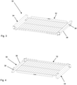
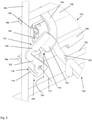
- the support device 30, which for all embodiments, first of all based on the Figures 2 to 4 is explained in general, comprises a support element 32 and two rail systems 34.
- the rail systems 34 each have at least two rails 36, 38 that can be moved relative to one another and are formed in the manner of a telescopic extension.
- a first, lower rail 36 is movably mounted in the second, upper rail 38 .
- a third rail can be arranged between the lower rails 36 and the upper rails 38 of the rail system 34, which is then movably mounted relative to the other rails 36, 38.
- the support element 32 is designed in the manner of a grate.
- the grate consists of a large number of metal support rods 40 which form a support surface for the food to be cooked (not shown).
- the support rods 40 are fixed to four holding rods 42 arranged transversely to the support rods.
- the support element 32 is fastened by means of two of the holding rods 42 to a respective upper side of the upper rails 38 of the rail systems 34, for example by a welded connection.
- the ends 44 of the two holding rods 42 are shaped approximately S-shaped, so that a first section 46 of the end 44 runs parallel to a side face 50 of the rails 38 and a second section 48 runs parallel to the upper side 52 of the rails 38 .
- the two lower rails 36 are each provided with two support elements 54 and 56 on an underside.
- the support elements 54, 56 are arranged at the ends of the two lower rails 36 of the rail systems 34.
- the rails 36 - and thus the support device 30 - can be held on the receptacle 14 of the household appliance 2 by means of the support elements 54 , 56 .
- the support device 30 is placed by means of the support elements 54, 56 on the receiving rods 18a of both receptacles 14 or their upper contact surfaces of said receiving rods 18a.
- the rear support element 56 which faces the rear wall 22 of the household appliance 2 when the support device 30 is installed, also each have a securing section 58, which additionally ensures that the support device, when the food is removed as a result of the weight of the food acting on the grate, during a tilting movement on the Recording 14 is held.
- the receptacle 14 can also accommodate other cooking product carriers, not shown in the figures, such as grills or baking trays without rail systems 34, which can then simply be placed with their edge between one of the pairs of rods 18 on each Side can be inserted and carried by the respective lower receiving rod 18a.
- figure 2 12 shows the support device 30 in a state in which the rail systems 34 are in an extended state, that is to say the upper rail 38 with the support element 32 is moved forward relative to the lower rail 36.
- foodstuffs (not shown) located on the support element 32 can be removed particularly easily from the interior 8 of the household appliance 2 .
- the support device 30 is mounted on the housing 6 in a manner that is indirectly force-transmitting, namely via the receptacles 14 . In particular, this eliminates the need to remove the entire carrying device 30 if only the cooking status of the food is to be checked or the food is to be placed in the interior 8 of the household appliance 2 or removed from it.
- figure 3 points towards figure 2 the support device 30 in a state in which the rail systems 34 are in a pushed-in state. It should now be ensured that the in figure 3 shown state is always present in an expanded state of the support device 30, or at least can be made permanently to avoid the user being hindered by the support element 32 or by the rails 36, 38 of the rail system 34, which could occur if this occurs as a result of a change in the orientation of the support device 30 in space - for example when the support device tilts 30 - would drive out unintentionally. In an installed state of the support device 30, on the other hand, both states shown should be possible. While figure 3 FIG.
- FIG figure 4 shows support 30, whether in an installed or removed condition, in a use orientation with upper rails 38 over lower rails 36
- FIG figure 4 the carrying device 30 in a dismantled state is rotated by 180° in relation to the usage orientation, which means that it is “upside down” so to speak.
- the user In this position, too, it should not be possible for the user to be hindered by the support element 32 or by the rails 36, 38 of the rail system 34 when the support device is removed, which could occur if this was the result of a change in the orientation of the support device 30 in space - would be unintentionally pulled out - for example, if the support device 30 tilts.
- the household appliance 2 therefore has two locking units of the same type, which are each assigned to one of the rail systems.
- the locking unit 100 comprises two locking elements 110 and 150 in the example shown.
- the locking element 110 is arranged directly on a support element 156 of the support device 130, the support device 130 being placed by means of the support element 156 on a receiving rod 18a of the receptacle 14 or one of its upper support surfaces.
- the lower rail 136 of the rail system 134 is coupled directly to the support element 156 .
- the second locking element 150 is arranged on the support device 130 such that it can rotate about an axis of rotation 152, with the locking element 150 being assigned directly to the upper rail 138 of the rail system 134, to which the support element 132 is connected by means of the ends 144 of its retaining rods 142.
- the locking unit 100 can be switched between a blocked state and a free state.
- the blocking state of the locking unit 100 corresponds to the blocking positions of the locking elements 110, 150, while the free state of the locking unit 100 corresponds to the locking elements 110, 150 being released.
- the free state of the locking unit 100 is particularly good based on the figures 5 and 6 recognizable. It is present when the locking elements 110, 150 are detached from one another, so that they prevent movement of the two rails 136 and 138 of the Rail system 134 relative to each other do not impede.
- the first locking element 110 in the example shown is provided with a transverse strut 114, by means of which the locking element 110 can strike a stop point 116 on a vertical strut 20b of the receptacle 14.
- the locking element 110 protrudes beyond the support element 132 .
- the carrying device 130 can be completely converted into its installed state by being inserted into the household appliance 2 .
- This does not result in a collision of the support element 132 with the receptacle 14.
- the desired collision of the locking element 110 with the receptacle 14 occurs, so that the latter automatically, i.e. without manual intervention by the user of the household appliance 2, pivots into its release and dissolves a form fit with the second locking element 150 .
- inserting the support device 130 into the household appliance 2 ensures that the locking unit 100 is automatically transferred to its free state, whereupon the rail system 134 is released and consequently the two rails 136, 138 can be moved relative to one another.
- the locking unit 100 is automatically transferred to its blocked state during the transfer of the support device 130 from its installed state to a disassembled state in which the support device 130 is removed from the domestic appliance and is therefore physically separated from the latter.
- the automatic transition to the blocking state is based on the fact that a center of gravity 118 of the locking element 110 is located eccentrically in relation to the axis of rotation 112 of the locking element 110 when the locking element 110 is in its release. Consequently, a line of action 120 of a weight acting on the locking element 110 as a result of its own weight runs under a lever arm 122 in relation to the axis of rotation 112.
- the weight force therefore causes a restoring moment on the locking element 110, as a result of which the locking element 110 automatically pivots from its release into a blocking position as soon as the locking element 110 is freely rotatable.
- the latter is the case at the moment when the carrying device 130 is detached from the receptacle 14 of the household appliance 2 in such a way that the stop of the locking element 110 on the vertical strut 20b of the receptacle 14 is eliminated.
- the locking element 110 has a head weight 124 which is arranged on a hook section 126 of the locking element 110 so that the center of gravity 118 is arranged on the “right side” of the axis of rotation 112 .
- the transfer of the locking element 110 in its blocking position means that the locking element 110, which is designed here in the form of a hook, engages with the hook portion 126 in a form-fitting manner with the second locking element 150, wherein the Hook section 126 moves into a recess 154 of the second locking element 150 .
- a position of the second locking element 150 does not initially change.
- the positive locking of the two locking elements 110, 150 corresponds to the blocking state of the locking unit 100, in the presence of which the two rails 136, 138 of the rail system 134 cannot be moved relative to one another. Consequently, the rail system 6 is prevented from being unintentionally extended. In this case, the rail system 134 is secured against this pulling out automatically, that is to say without any manual intervention by the user of the household appliance 2. A particularly high degree of security against incorrect operation is thereby achieved.
- the blocking state of the locking unit 100 is particularly good based on the Figures 7 and 8 recognizable. It is worth mentioning here that the blocking state of the locking unit 100 can be present when the locking elements 110, 150 are in different blocking positions.
- a first scenario has already been described above.
- the carrying device 130 is removed from the household appliance 2 starting from its installed state, with the carrying device 130 being pulled out of the interior 8 along the lower receiving rod 18a of the receptacle 14 .
- the locking element 110 loses its stop on the rear vertical strut 20b and, due to its own weight, is automatically rotated into its blocking position and brought into engagement with the second locking element 150 .
- the two locking elements 110, 150 are then each in a first blocking position. This is in figure 7 shown.
- the carrying device 130 is in a use orientation.
- the support element 132 is oriented at least substantially horizontally in space, so that an object can be stored on a storage level of the support element 132, specifically in the figure 3 shown position.
- the support element 132 designed as a grate is therefore suitable for receiving a particular item to be cooked.
- the carrying element 132 is therefore intended to hold an object.
- the support device 130 is in its expanded state, in which it is physically separated from the housing 6 of the household appliance 2, it is nevertheless possible to convert the support device 130 into a different orientation, for example into a reverse orientation, as is shown in figure 4 is shown.
- a reverse orientation as is shown in figure 4 is shown.
- the carrying device 130 is rotated through 180° with respect to the usage orientation, so that it is, so to speak, oriented the wrong way round or “upside down”.
- the rail system 134 is also secured against unintentional extension with this orientation of the carrying device 130 and remains so when the carrying device 130 is subsequently tilted into a different orientation.
- the second locking element 150 can be rotated about the axis of rotation 152 relative to the support device 130 in the exemplary embodiment shown.
- This offers the advantage that second locking element 150 can move as a result of the changing orientation of the weight force acting on it, as a result of which the form fit with the first locking element 110 is maintained even when it rotates due to the force of gravity.
- figure 8 show the second locking element 150 in a blocking position pivoted “upwards” in the drawing.
- the locking element 150 is always pivoted "down” in the reverse orientation of the support device 130, that is to say in each case following a direction of action of gravity.
- the representation in figure 8 shows the carrying device 130 upside down to a certain extent.
- the rotatability of the second locking element 150 means that the latter, with its recess 154, maintains the form fit with the first locking element 110, so that the result is that the rail system 134 is blocked against unintentional removal regardless of the orientation of the carrying device 130 in space.
- the locking unit 100 is therefore in its blocking state, as desired, independently of the alignment of the support device 130 .
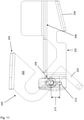
- the locking unit 200 includes a storage portion 202, a locking element 204 and a guide device 206, which in the figures 12 and 13 1, and is disposed on a lower rail 236 of support assembly 230.
- FIG. 9 a second embodiment of a locking unit 200 not according to the invention is shown and described below.
- the locking unit 200 includes a storage portion 202, a locking element 204 and a guide device 206, which in the figures 12 and 13 1, and is disposed on a lower rail 236 of support assembly 230.
- the carrying device 230 can be placed on the receptacle 14 of the household appliance 2 by means of the storage section 202 and can thus be transferred to its installed state.
- the storage section 202 has a storage surface 208 which, when the carrying device 230 is in the installed state, is in contact with the bearing surface of the lower receiving rod 18a of the receptacle 14 .
- a holding element 209 arranged laterally on the locking unit 200 prevents the carrying device 230 from tipping as a result of asymmetrical loading of a carrying element 232 of the carrying device 230.
- the locking unit 200 is provided with an elongated hole 212 which is oriented perpendicularly in relation to the plane that forms the support element 232 .
- the elongated hole 212 is oriented vertically.
- the elongated hole 212 has a semicircular widening 216 on one side, which is arranged in a central region of the elongated hole 212.
- the widening 216 thus has an effective area in which a width 218 of the elongated hole 212 is greater than outside the effective area.
- the locking element 204 comprises a stop section 12, a hook section 222 and a connecting section 224.
- the connecting section 224 is designed in the manner of a web and is provided with a circular opening 225 in a central region.
- a partial bolt 226, the cross section of which is formed by a semicircular surface, is passed through the opening 225 therethrough.
- the diameter 227 of the partial bolt 226 corresponds approximately to the diameter 217 of the widening 216 of the elongated hole 212.
- the partial bolt 226 is as in FIG figure 12 shown immovably anchored to locking member 204 by nut 228 .
- the stop section 220 of the locking element 204 which is arranged at one end of the connecting section 224, has an L-shape and is bent at its free end by 90° with respect to a longitudinal axis 229 of the partial bolt 226, which at the same time forms an axis of rotation 223. so that a longitudinal axis 221 of the stop section 220 runs parallel to the axis of rotation 223 of the partial bolt 226 .
- the hook portion 222 is arranged at the other end of the connecting portion 224 and has a U-shaped recess 219 on. An opening cross section 215 of the recess 219 is larger than the diameter of a retaining rod 242 of the support element 232.
- the guide device 206 is L-shaped and has a circular opening (not visible in the figure).
- the partial bolt 226 is guided through the slot 212 of the locking unit 200 and the opening of the guide device 206, with an additional spacer element 211 in the form of a ring being arranged between the slot 212 and the locking element 204.
- the end of the partial bolt 226 facing away from the locking element 204 is rotatably mounted in the opening of the guide device 206 .
- the partial bolt 226 is mounted in a displaceable manner along the elongated hole 212 .
- the locking element 204 is connected to the guide device 206 in a force-transmitting manner in such a way that a movement of the guide device 206 along the elongated hole 212 is transferred to the locking element 204 .
- the locking element 204 can thus be transferred between a plurality of fixed positions and a rotational position. In the fixed positions, which in the figures 9 , 10 and 12 are shown, rotation of the locking element 204 is at least essentially prevented. If the partial bolt 226 is outside the effective range of the widening 216 , free rotation of the locking element 204 is prevented in that the partial bolt 226 can only be rotated up to a stop of the same at the elongated hole 212 . This is caused by the fact that the diameter 227 of the partial bolt 226 is larger than the width 218 of the elongated hole 212.
- locking member 204 In a rotational position of locking element 204, on the other hand, which figure 11 As shown, locking member 204 is rotatable.
- the locking element 204 assumes the rotational position when the partial bolt 226 is in the effective range of the widening 216 .
- the area of action is dimensioned in such a way that the partial bolt 226 can be rotated freely in the area of action.
- the twistability is only thereby limited that the locking unit 200 has a stop portion 201 which is arranged parallel to the axis of rotation 223 of the partial bolt 226.
- the locking element 204 hits the stop section 210, which is located in figure 12 as shown, thus preventing rotation of the locking member 204 beyond this point.
- the locking element 204 In the dismantled state, the locking element 204 is displaced into a maximum position in the elongated hole 212 as a result of the force of gravity acting on it.
- the partial bolt 226 assumes a first maximum position (shown in figure 9 and figure 12 ) if the carrying device 230 is in a usage orientation (shown in figure 3 ) is located.
- the orientation of use is characterized in that the carrying device 230 is usually used in this orientation to cook the food.
- the second maximum position (shown in figure 10 ) is occupied by partial bolt 226 when support means 230 is in a reverse orientation (shown in FIG figure 4 ) is present, in which the support device 230 is rotated by 180° about a horizontal relative to the usage orientation.
- the locking element 204 In the maximum positions, the locking element 204 is in a fixed position, in which rotation of the locking element 204 is blocked. The locking element 204 is thus in its blocking position.
- the hook section 222 of the locking element 204 engages, as in figure 12 shown, forms a positive fit around the retaining rod 242 of the support element 232, and thus prevents the upper rails 238 and the support element 232 attached thereto from being pulled out relative to the lower rails 236 of the rail systems 234.
- the carrying device 230 is placed on the lower receiving rods 18a of the receptacles 14 by means of the storage section 202 of the locking unit 200 .
- the guide device 206 is moved along the longitudinal axis 214 of the slot 212 in such a way that an underside of the same that faces the lower receiving rod 18a is aligned parallel to the storage surface 208 of the storage section 202 .
- the latter is also moved along the elongated hole 212.
- the path that locking element 204 travels along longitudinal axis 214 of slot 212 corresponds precisely to the distance between the first maximum position of locking element 204 and the position in which partial bolt 226 is located in the effective area of widening 216.
- the partial pin 226 is thus automatically shifted into the effective area of the widening 216 in the course of the transfer of the carrying device 230 into its installed state.
- the abutment section 220 abuts against the rear vertical connecting rod 20b when the support device 230 is transferred into its installed state.
- the locking element 204 is rotated about the axis of rotation of the partial bolt 226, so that the locking element 204 is transferred into its release. This will make the Hook portion 222 released the support bar 242, whereby an extension of the rail systems 234 is free.
- the locking unit 200 is now in its free state.
- the carrying device 230 can therefore be pulled out relative to the housing 6 of the household appliance 2 .
- a support device 330 according to a third exemplary embodiment not according to the invention is provided with two locking elements 300 which are each arranged on the lower rails 336 of the two rail systems 334 .
- locking units are constituted by the locking elements 300 themselves and are identical to them.
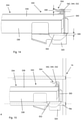
- figure 14 shows a vertical section through a locking element 300 and through the support device 330.
- the locking element 300 is designed as a spring element.
- the locking element 300 has a fastening section 302 and a holding section 304 .
- the fastening section 302 serves to fasten the locking element 300 to the lower rail 336 of the rail system 334. In this case, a free end of the fastening section 302 is firmly connected to the rail 336, for example by welding.
- the holding section 304 enables the formation of a form fit with the support device 330, in particular an end 344 of a support rod 342 of the support element 332, which is connected, preferably welded, to the upper rail as described above.
- a cross section of the holding section 304 is approximately S-shaped and thus enables the holding rod 342 to be gripped in a form-fitting manner.
- the locking element 300 blocks the extension of the rail system 334 by forming a form fit with the end 344 of the retaining rod 342, whereby as a result of the connection of the locking element 300 to the lower rail 336 and the support element 332 to the upper rail 338, the two rails 336 and 338 are coupled to each other.
- the state of the support device 330 shown corresponds to its expansion state.
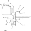
- FIG. 15 shows a vertical section through the support device 330 and the locking element 300 in an installed state of the support device 330 and the resulting free state of the locking unit 300.
- the fastening section 302 is deformed in such a way that the same runs parallel to the lower receiving rod 18a of the receptacle and completely on it rests.
- the holding section 304 is moved against the acting weight force by the support device 330 is placed on the fastening section 302 to a certain extent.
- the deflection path is adapted to a diameter of the end 344 of the retaining rod 342, so that the retaining rod 342 of the support element 332 can be guided through the resulting gap when the rail system 334 is pulled out.
- a maximum deformation path 306 of the locking element 300 exceeds its engagement depth 308 on the retaining rod 342.
- the locking element 300 is automatically transferred from its free state to its blocked state due to the absence of the stop on the receptacle as a result of the elastic deformation in the locking element 300 stored restoring force. It is therefore not possible to pull out the rail system 334 for the time being. This applies both to a usage orientation of the carrying device 330 and to a reverse orientation rotated by 180°.
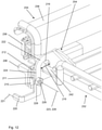
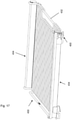
- the Figures 16 to 19 12 show a fourth exemplary embodiment of a carrying device 430 that is not according to the invention.
- the locking units 400 are not arranged in the rear area but in the front area of the rail systems 434, see FIG figure 16 and 17 can be seen.
- the locking elements 402 of the locking units 400 are automatically and without any further action on the part of the user transferred to their free state when the carrying device 430 is inserted into the receptacle 14, ie when the carrying device 430 is transferred into its installed state.
- Only one rail system 434 and one locking unit 400 are referred to below, although locking units 434 are provided on both rail systems 434 .
- support member 402 has been omitted and only one track system 434 is shown.
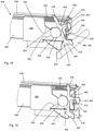
- a rotating element 404 is rotatably mounted on the lower rail 436 of a rail system 434 .
- the rotating element 404 comprises, starting from a central bearing area 406, a hook arm 410, a spring arm 416 and an actuating arm 418.
- the bearing area 406 has an opening which cannot be seen in the figures because a bearing pin 408 is inserted through it, which is attached to the lower rail 436 is attached. From the storage area 406 extend into the Figures 17 to 19 to the left two stops 424 and 426 formed on the rotary element 404.
- the spring arm 416 which points upwards, together with a holding element 450, which is also fastened to the lower rail 436, clamps in a helical spring 422 and presses it more depending on the rotary position of the rotary element 404 or less together.
- the actuating arm 418 extends into the Figures 17 to 19 and thus in the Orientation of use of the support device 430 downwards. He has a molded contact area 420 in which in the figures 16 and 18 shown installed state of the support device 430 rests against an angled portion 460 of the lower receiving rod 18a.
- this angled section 460 of the lower receiving rod 18a is located in the front area of the respective side wall 16 facing towards the door 12 and is welded to the front vertical connecting rod 20a.
- the hook arm 410 which is in the Figures 17 to 19 extends to the right, has a hook 412, the actual locking element 402, at its end facing away from the storage area 406. This is designed and placed in such a way that it can reach through a slot-shaped opening 440, regardless of the rotational position of the rotary element 404, which is in an angled End 439 of the upper rail 438 is located.
- the entire locking unit 400 is in each case arranged on that side of the rail system 434 which is directed towards the closer side wall 16 of the housing 2 . It is therefore located between the respective rails 436 or 438 and the respective receptacle 14 when the support device 430 is in the installed state and is therefore not visible to the user.
- the hook arm 410 is rotated upward and the hook 412 is no longer engaged with the rim 442 of the opening 440.
- the latch assembly 400 is in its free state.
- the spring arm 416 is also rotated in that direction. In doing so, it compresses the helical spring 422 against the holding element 450 and thus during the course of the rotation.
- the entire rotating element 404 and thus in particular the locking element 402 is thus pretensioned against the force of the spring 422 and is pressed into a free state of the locking unit 400 .
- the two rails 436 and 438 can be moved relative to one another and the support element 432 can be pulled out of the interior 8 together with the upper rails 438, for example for loading and unloading or for checking the food to be cooked during the cooking process.
- the hook 412 grips the edge 442 of the opening 440 and creates a form fit between the upper rail 438 and lower rail 436 .
- the blocking state of the locking element 402 is then automatically generated. If, on the other hand, the lower rail 436 is pulled a little further out of the upper rail 438 (not shown) when the support device 430 is removed, the locking element 402 can be locked by pushing the lower rail 436 into the upper rail 438 by the user.
- the hook 412 is provided with a starting bevel 414 which, during this insertion process, briefly rotates the rotary element 404 counterclockwise against the force of the helical spring 422 and moves the hook arm 410 upwards.
- the spring 422 moves the rotary element 404 clockwise again and brings the hook 412 and thus the locking element 402 into the blocking state of the locking unit 400.
- a lower stop 426 presses in the in figure 19 shown state of the rotary element 404 against the lower 454 incline of the holding element 450. This prevents the hook arm 410 from being rotated so far when the carrying device 430 is in the dismantled state and the locking device 400 is in a state in which the hook 412 does not engage in the opening 440 that the starting bevel 414 is outside of its effective range in relation to the opening 440.
- the lower stop 426 prevents the rotating element 404 from rotating into a position in which the coil spring could fall out of its clamping between the spring arm 416 and the retaining element 450 .
- This exemplary embodiment of a carrying device 430 also has locking devices 400, the locking elements 402 of which act securely when the carrying device 430 is in a disassembled state, both in its usage orientation and in a reverse orientation rotated by 180°.
Landscapes
- Engineering & Computer Science (AREA)
- Chemical & Material Sciences (AREA)
- Combustion & Propulsion (AREA)
- Mechanical Engineering (AREA)
- General Engineering & Computer Science (AREA)
- Food Science & Technology (AREA)
- Physics & Mathematics (AREA)
- Thermal Sciences (AREA)
- Drawers Of Furniture (AREA)
- Cookers (AREA)
- Sink And Installation For Waste Water (AREA)
Claims (5)
- Appareil électroménager (2) ou appareil industriel permettant de nettoyer, de stocker ou de cuire des objets, comprenant un boîtier (6) formé de parois (4), au moyen duquel un espace intérieur (8) est spatialement clos, ainsi qu'au moins un dispositif de support (130) pouvant être retiré de l'espace intérieur (8),• dans lequel le dispositif de support (130) comprend au moins un système de rails (134) comportant au moins deux rails (136 et 138) reliés l'un à l'autre et mobiles l'un par rapport à l'autre, ainsi qu'au moins un élément de support (132),• dans lequel le système de rails (134), lorsque le dispositif de support (130) est présent, dans un état monté, est monté sur le boîtier (6) de manière à transmettre une force de telle sorte que l'élément de support (132) est mobile par rapport au boîtier (6) par déploiement du système de rails (134),• dans lequel une unité de verrouillage (100) disposée sur le dispositif de support (130) et comprenant au moins un élément de verrouillage (110) peut être transférée entre un état de blocage et un état libre,• dans lequel l'unité de verrouillage (100) est présente dans son état de blocage lorsque le dispositif de support (130) est présent dans son état démonté, dans lequel le dispositif de support (130) est physiquement séparé du boîtier (6), et lorsque le dispositif de support est présent, l'élément de verrouillage (110) bloque le déploiement du système de rails (134) en formant une complémentarité de forme, et• dans lequel l'unité de verrouillage (100) est présente dans son état libre lorsque le dispositif de transport (5) est présent dans son état monté, et lorsqu'il est présent, l'élément de verrouillage (102) libère le déploiement du système de rails (134),• et dans lequel l'unité de verrouillage (100) comprend au moins un second élément de verrouillage (150) disposé de manière rotative sur le dispositif de support (130), dans lequel les éléments de verrouillage (110, 150) sont affectés au moins indirectement à différents rails (136, 138) du système de rails (134),
caractérisé en ce
que l'état de blocage de l'unité de verrouillage (100) peut être obtenu au moyen d'une pluralité de positions de blocage des éléments de verrouillage (110, 150), dans lesquelles lesdits éléments de verrouillage sont respectivement tournés différemment autour de leur axe de rotation (112, 152) respectif par rapport au dispositif de support (130) de telle sorte que les éléments de verrouillage (110, 150) sont présents conjointement dans une première position de blocage lorsque le dispositif de support (130), se trouvant dans son état démonté, est présent dans une orientation d'utilisation dans laquelle l'élément de support (132) est fourni pour recevoir un objet, et les éléments de verrouillage sont présents dans une seconde position de blocage lorsque le dispositif de support (130), se trouvant dans son état démonté, est présent dans une orientation inverse dans laquelle le dispositif de support (5) est tourné de 180 ° par rapport à l'orientation d'utilisation de telle sorte que l'unité de verrouillage (100) est respectivement présente dans son état de blocage lorsque le dispositif de support (130) est présent à la fois dans son orientation d'utilisation et dans son orientation inverse. - Appareil électroménager (2) ou appareil industriel selon la revendication précédente, caractérisé en ce que les deux éléments de verrouillage (110, 150) sont respectivement disposés sur le dispositif de support (5) de manière à pouvoir tourner autour d'un axe de rotation (112, 152), dans lequel les axes de rotation (112, 152) des éléments de verrouillage (110, 150) sont de préférence orientés parallèlement les uns aux autres.
- Appareil électroménager (2) ou appareil industriel selon au moins l'une quelconque des revendications précédentes, caractérisé par au moins un réceptacle (14) disposé sur le boîtier (6) de manière à transmettre une force et adapté et conçu pour recevoir le dispositif de support (130), dans lequel, de préférence le dispositif de support (130) peut être placé sur une surface d'appui du réceptacle (14).
- Appareil électroménager (2) ou appareil industriel selon au moins l'une quelconque des revendications précédentes, caractérisé en ce que l'unité de verrouillage (100) est associée directement ou indirectement à un rail (136, 138) du système de rails (134), de préférence à un rail inférieur (136).
- Appareil électroménager (2) ou appareil industriel selon au moins l'une quelconque des revendications précédentes, caractérisé en ce que l'élément de support (132) est associé directement ou indirectement de manière à transmettre une force à un rail (136, 138) du système de rails (134), de préférence à un rail supérieur (138).
Priority Applications (1)
| Application Number | Priority Date | Filing Date | Title |
|---|---|---|---|
| EP21188129.7A EP3933279B1 (fr) | 2019-04-24 | 2020-04-07 | Appareil électroménager ou appareil industriel |
Applications Claiming Priority (3)
| Application Number | Priority Date | Filing Date | Title |
|---|---|---|---|
| DE102019110605 | 2019-04-24 | ||
| DE102019115976.8A DE102019115976A1 (de) | 2019-06-12 | 2019-06-12 | Haushaltsgerät oder Gewerbegerät sowie Tragsystem für ein solches und Verfahren zur Sicherung eines solchen |
| DE102019116189.4A DE102019116189A1 (de) | 2019-06-14 | 2019-06-14 | Gerät zur Reinigung, Lagerung oder Garung von Gegenständen |
Related Child Applications (2)
| Application Number | Title | Priority Date | Filing Date |
|---|---|---|---|
| EP21188129.7A Division EP3933279B1 (fr) | 2019-04-24 | 2020-04-07 | Appareil électroménager ou appareil industriel |
| EP21188129.7A Division-Into EP3933279B1 (fr) | 2019-04-24 | 2020-04-07 | Appareil électroménager ou appareil industriel |
Publications (3)
| Publication Number | Publication Date |
|---|---|
| EP3730842A2 EP3730842A2 (fr) | 2020-10-28 |
| EP3730842A3 EP3730842A3 (fr) | 2020-12-16 |
| EP3730842B1 true EP3730842B1 (fr) | 2022-03-02 |
Family
ID=70227798
Family Applications (2)
| Application Number | Title | Priority Date | Filing Date |
|---|---|---|---|
| EP20168383.6A Active EP3730842B1 (fr) | 2019-04-24 | 2020-04-07 | Appareil électroménager ou appareil industriel avec système de support |
| EP21188129.7A Active EP3933279B1 (fr) | 2019-04-24 | 2020-04-07 | Appareil électroménager ou appareil industriel |
Family Applications After (1)
| Application Number | Title | Priority Date | Filing Date |
|---|---|---|---|
| EP21188129.7A Active EP3933279B1 (fr) | 2019-04-24 | 2020-04-07 | Appareil électroménager ou appareil industriel |
Country Status (3)
| Country | Link |
|---|---|
| US (1) | US11311143B2 (fr) |
| EP (2) | EP3730842B1 (fr) |
| DE (1) | DE202020005548U1 (fr) |
Families Citing this family (7)
| Publication number | Priority date | Publication date | Assignee | Title |
|---|---|---|---|---|
| DE102020124881A1 (de) | 2020-09-24 | 2022-03-24 | Paul Hettich Gmbh & Co. Kg | Haushaltsgerät |
| DE102020124880A1 (de) | 2020-09-24 | 2022-03-24 | Paul Hettich Gmbh & Co. Kg | Backofen |
| DE102021131558B4 (de) * | 2021-12-01 | 2025-07-03 | Miele & Cie. Kg | Teleskopiereinrichtung für ein Gargerät, Gargerät mit einer Teleskopiereinrichtung und Verfahren zum Betrieb einer Teleskopiereinrichtung oder eines Gargeräts |
| WO2024199621A1 (fr) * | 2023-03-24 | 2024-10-03 | Paul Hettich Gmbh & Co. Kg | Appareil électroménager doté d'un système d'étagère |
| US12372247B2 (en) | 2023-04-26 | 2025-07-29 | Sharkninja Operating Llc | Systems and methods for cooking pizza |
| US12035845B1 (en) | 2023-04-26 | 2024-07-16 | Sharkninja Operating Llc | Systems and methods for cooking pizza |
| USD1104596S1 (en) | 2023-05-31 | 2025-12-09 | Sharkninja Operating Llc | Cooking device |
Family Cites Families (19)
| Publication number | Priority date | Publication date | Assignee | Title |
|---|---|---|---|---|
| FR2608905B1 (fr) * | 1986-12-30 | 1989-12-08 | Signaux Entr Electriques | Glissiere a billes telescopique en particulier pour tiroirs |
| US6244678B1 (en) * | 1999-09-09 | 2001-06-12 | Thomas Regout Usa, Inc. | Drawer slide with front-mounted stop/anti-rebound mechanism |
| DE19951267B4 (de) | 1999-10-25 | 2005-05-12 | Accuride International Gmbh | Gargutträgersystem für einen Backofen |
| US6817685B2 (en) * | 2000-08-08 | 2004-11-16 | Accuride International Inc. | Release mechanism for drawer slide latches |
| DE10051153B4 (de) | 2000-10-16 | 2004-08-26 | Accuride International Gmbh | Gargutträgersystem für einen Backofen |
| US20060065265A1 (en) * | 2004-09-27 | 2006-03-30 | Bsh Home Appliances Corporation | Extendable oven rack assembly |
| US7458651B1 (en) * | 2006-11-08 | 2008-12-02 | Atc Hardware Systems, Inc. | Drawer slide with adjustable strike |
| DE102008064850B3 (de) * | 2008-02-28 | 2019-02-21 | Gronbach Forschungs- Und Entwicklungs Gmbh & Co. Kg | Teleskop-Auszugsführung für ein Gerät oder Möbel |
| DE202009002073U1 (de) * | 2009-04-17 | 2010-09-09 | Paul Hettich Gmbh & Co. Kg | Auszugssystem und Haushaltsgerät |
| US8490801B2 (en) * | 2009-05-22 | 2013-07-23 | Electrolux Home Products, Inc. | Glide rack |
| US20120097147A1 (en) * | 2010-10-22 | 2012-04-26 | General Electric Company | Extension rack assembly for consumer appliance and consumer appliance incorporating same |
| DE102013102948B4 (de) * | 2012-10-12 | 2024-02-08 | Paul Hettich Gmbh & Co. Kg | Auszugsführung |
| US9022496B2 (en) * | 2013-03-20 | 2015-05-05 | General Electric Company | Vertically adjustable shelf support assembly for an appliance |
| DE102014214169A1 (de) * | 2014-07-21 | 2016-01-21 | BSH Hausgeräte GmbH | Teleskopauszugssystem und Haushaltsgargerät |
| KR101703683B1 (ko) * | 2015-05-01 | 2017-02-07 | 주식회사 전한슬라이드 | 받침선반 록킹장치 |
| DE102017107544A1 (de) * | 2016-04-08 | 2017-10-12 | Paul Hettich Gmbh & Co. Kg | Schiebe- und Hubmechanismus für ein Möbel oder Haushaltsgerät und Möbel oder Haushaltsgerät mit einem derartigen Schiebe- und Hubmechanismus |
| KR102342578B1 (ko) * | 2017-04-28 | 2021-12-23 | 삼성전자주식회사 | 조리기기 |
| DE102019124058B3 (de) * | 2019-09-09 | 2020-11-12 | Accuride International Gmbh | Gerät zur Reinigung, Lagerung oder Garung von Gegenständen |
| TWI702900B (zh) * | 2019-10-07 | 2020-08-21 | 川湖科技股份有限公司 | 機櫃及其滑軌套件 |
-
2020
- 2020-04-07 DE DE202020005548.4U patent/DE202020005548U1/de active Active
- 2020-04-07 EP EP20168383.6A patent/EP3730842B1/fr active Active
- 2020-04-07 EP EP21188129.7A patent/EP3933279B1/fr active Active
- 2020-04-16 US US16/850,368 patent/US11311143B2/en active Active
Also Published As
| Publication number | Publication date |
|---|---|
| EP3730842A3 (fr) | 2020-12-16 |
| DE202020005548U1 (de) | 2021-10-29 |
| EP3933279A1 (fr) | 2022-01-05 |
| EP3933279B1 (fr) | 2023-11-01 |
| EP3730842A2 (fr) | 2020-10-28 |
| US11311143B2 (en) | 2022-04-26 |
| US20200337496A1 (en) | 2020-10-29 |
Similar Documents
| Publication | Publication Date | Title |
|---|---|---|
| EP3730842B1 (fr) | Appareil électroménager ou appareil industriel avec système de support | |
| WO2017174793A1 (fr) | Mécanisme de poussée et de levée pour un meuble ou un appareil électroménager et meuble ou appareil électroménager comportant un tel mécanisme de poussée et de levée | |
| DE202004005475U1 (de) | Tragboden eines Küchengerätes | |
| WO2016131952A1 (fr) | Mécanisme de coulissement et de levage d'un réceptacle d'un meuble ou d'un appareil ménager, meuble et appareil ménager | |
| EP3793407B1 (fr) | Mécanisme de coulissement et de pivotement d'une tablette/clayette d'un meuble ou d'un appareil électroménager, et meuble ou appareil électroménager | |
| DE10153621A1 (de) | Kältegerät mit verstellbaren Fachböden | |
| EP1306622A1 (fr) | Système de rails pour support de plats dans un four de cuisine | |
| EP1642066B1 (fr) | Systeme de tablettes coulissantes permettant de recevoir des produits a cuire | |
| EP3788911B1 (fr) | Appareil de nettoyage, de stockage ou de cuisson d'objets | |
| DE10206854C1 (de) | Ausziehsperre für übereinander angeordnete Schubladen | |
| DE102014201027B4 (de) | Aufnahmevorrichtung, Spülgutaufnahme und wasserführendes Haushaltsgerät | |
| DE69811040T2 (de) | Türschliessvorrichtung für ein Haushaltsgerät, beispielsweise eine Geschirrspülmaschine | |
| EP3515276B1 (fr) | Lave-vaisselle domestique | |
| DE102017211203B4 (de) | Hebesystem für eine Haushaltsgeschirrspülmaschine oder ein Möbel | |
| EP4286749B1 (fr) | Système de fixation rapide pour une glissière télescopique | |
| CH647983A5 (de) | Ablageschrank. | |
| EP0376159B1 (fr) | Appareil de manipulation pour caisses d'entrepôt | |
| DE102019115976A1 (de) | Haushaltsgerät oder Gewerbegerät sowie Tragsystem für ein solches und Verfahren zur Sicherung eines solchen | |
| DE102019116189A1 (de) | Gerät zur Reinigung, Lagerung oder Garung von Gegenständen | |
| EP1929223A1 (fr) | Appareil refrigerant a clayette de rangement | |
| DE3408686C2 (fr) | ||
| EP2491816B1 (fr) | Chariot | |
| EP1041906A1 (fr) | Armoire a tiroirs | |
| DE60118237T2 (de) | Anordnung in einem ofen, insbesondere zur verwendung im haushalt | |
| AT408058B (de) | Ausziehvorrichtung für hochschränke |
Legal Events
| Date | Code | Title | Description |
|---|---|---|---|
| REG | Reference to a national code |
Ref country code: DE Ref legal event code: R138 Ref document number: 202020005548 Country of ref document: DE Free format text: GERMAN DOCUMENT NUMBER IS 502020000713 |
|
| PUAI | Public reference made under article 153(3) epc to a published international application that has entered the european phase |
Free format text: ORIGINAL CODE: 0009012 |
|
| STAA | Information on the status of an ep patent application or granted ep patent |
Free format text: STATUS: THE APPLICATION HAS BEEN PUBLISHED |
|
| AK | Designated contracting states |
Kind code of ref document: A2 Designated state(s): AL AT BE BG CH CY CZ DE DK EE ES FI FR GB GR HR HU IE IS IT LI LT LU LV MC MK MT NL NO PL PT RO RS SE SI SK SM TR |
|
| AX | Request for extension of the european patent |
Extension state: BA ME |
|
| PUAL | Search report despatched |
Free format text: ORIGINAL CODE: 0009013 |
|
| AK | Designated contracting states |
Kind code of ref document: A3 Designated state(s): AL AT BE BG CH CY CZ DE DK EE ES FI FR GB GR HR HU IE IS IT LI LT LU LV MC MK MT NL NO PL PT RO RS SE SI SK SM TR |
|
| AX | Request for extension of the european patent |
Extension state: BA ME |
|
| RIC1 | Information provided on ipc code assigned before grant |
Ipc: F24C 15/16 20060101AFI20201112BHEP |
|
| STAA | Information on the status of an ep patent application or granted ep patent |
Free format text: STATUS: REQUEST FOR EXAMINATION WAS MADE |
|
| 17P | Request for examination filed |
Effective date: 20210616 |
|
| RBV | Designated contracting states (corrected) |
Designated state(s): AL AT BE BG CH CY CZ DE DK EE ES FI FR GB GR HR HU IE IS IT LI LT LU LV MC MK MT NL NO PL PT RO RS SE SI SK SM TR |
|
| GRAP | Despatch of communication of intention to grant a patent |
Free format text: ORIGINAL CODE: EPIDOSNIGR1 |
|
| STAA | Information on the status of an ep patent application or granted ep patent |
Free format text: STATUS: GRANT OF PATENT IS INTENDED |
|
| RIC1 | Information provided on ipc code assigned before grant |
Ipc: A47J 27/04 20060101ALI20211101BHEP Ipc: A47L 15/50 20060101ALI20211101BHEP Ipc: F24C 15/16 20060101AFI20211101BHEP |
|
| INTG | Intention to grant announced |
Effective date: 20211202 |
|
| GRAS | Grant fee paid |
Free format text: ORIGINAL CODE: EPIDOSNIGR3 |
|
| GRAA | (expected) grant |
Free format text: ORIGINAL CODE: 0009210 |
|
| STAA | Information on the status of an ep patent application or granted ep patent |
Free format text: STATUS: THE PATENT HAS BEEN GRANTED |
|
| AK | Designated contracting states |
Kind code of ref document: B1 Designated state(s): AL AT BE BG CH CY CZ DE DK EE ES FI FR GB GR HR HU IE IS IT LI LT LU LV MC MK MT NL NO PL PT RO RS SE SI SK SM TR |
|
| REG | Reference to a national code |
Ref country code: GB Ref legal event code: FG4D Free format text: NOT ENGLISH |
|
| REG | Reference to a national code |
Ref country code: CH Ref legal event code: EP Ref country code: AT Ref legal event code: REF Ref document number: 1472536 Country of ref document: AT Kind code of ref document: T Effective date: 20220315 |
|
| REG | Reference to a national code |
Ref country code: DE Ref legal event code: R096 Ref document number: 502020000713 Country of ref document: DE |
|
| REG | Reference to a national code |
Ref country code: IE Ref legal event code: FG4D Free format text: LANGUAGE OF EP DOCUMENT: GERMAN |
|
| REG | Reference to a national code |
Ref country code: GB Ref legal event code: 746 Effective date: 20220506 |
|
| REG | Reference to a national code |
Ref country code: LT Ref legal event code: MG9D |
|
| REG | Reference to a national code |
Ref country code: NL Ref legal event code: MP Effective date: 20220302 |
|
| PG25 | Lapsed in a contracting state [announced via postgrant information from national office to epo] |
Ref country code: SE Free format text: LAPSE BECAUSE OF FAILURE TO SUBMIT A TRANSLATION OF THE DESCRIPTION OR TO PAY THE FEE WITHIN THE PRESCRIBED TIME-LIMIT Effective date: 20220302 Ref country code: RS Free format text: LAPSE BECAUSE OF FAILURE TO SUBMIT A TRANSLATION OF THE DESCRIPTION OR TO PAY THE FEE WITHIN THE PRESCRIBED TIME-LIMIT Effective date: 20220302 Ref country code: NO Free format text: LAPSE BECAUSE OF FAILURE TO SUBMIT A TRANSLATION OF THE DESCRIPTION OR TO PAY THE FEE WITHIN THE PRESCRIBED TIME-LIMIT Effective date: 20220602 Ref country code: LT Free format text: LAPSE BECAUSE OF FAILURE TO SUBMIT A TRANSLATION OF THE DESCRIPTION OR TO PAY THE FEE WITHIN THE PRESCRIBED TIME-LIMIT Effective date: 20220302 Ref country code: HR Free format text: LAPSE BECAUSE OF FAILURE TO SUBMIT A TRANSLATION OF THE DESCRIPTION OR TO PAY THE FEE WITHIN THE PRESCRIBED TIME-LIMIT Effective date: 20220302 Ref country code: ES Free format text: LAPSE BECAUSE OF FAILURE TO SUBMIT A TRANSLATION OF THE DESCRIPTION OR TO PAY THE FEE WITHIN THE PRESCRIBED TIME-LIMIT Effective date: 20220302 Ref country code: BG Free format text: LAPSE BECAUSE OF FAILURE TO SUBMIT A TRANSLATION OF THE DESCRIPTION OR TO PAY THE FEE WITHIN THE PRESCRIBED TIME-LIMIT Effective date: 20220602 |
|
| PG25 | Lapsed in a contracting state [announced via postgrant information from national office to epo] |
Ref country code: PL Free format text: LAPSE BECAUSE OF FAILURE TO SUBMIT A TRANSLATION OF THE DESCRIPTION OR TO PAY THE FEE WITHIN THE PRESCRIBED TIME-LIMIT Effective date: 20220302 Ref country code: LV Free format text: LAPSE BECAUSE OF FAILURE TO SUBMIT A TRANSLATION OF THE DESCRIPTION OR TO PAY THE FEE WITHIN THE PRESCRIBED TIME-LIMIT Effective date: 20220302 Ref country code: GR Free format text: LAPSE BECAUSE OF FAILURE TO SUBMIT A TRANSLATION OF THE DESCRIPTION OR TO PAY THE FEE WITHIN THE PRESCRIBED TIME-LIMIT Effective date: 20220603 Ref country code: FI Free format text: LAPSE BECAUSE OF FAILURE TO SUBMIT A TRANSLATION OF THE DESCRIPTION OR TO PAY THE FEE WITHIN THE PRESCRIBED TIME-LIMIT Effective date: 20220302 |
|
| PG25 | Lapsed in a contracting state [announced via postgrant information from national office to epo] |
Ref country code: NL Free format text: LAPSE BECAUSE OF FAILURE TO SUBMIT A TRANSLATION OF THE DESCRIPTION OR TO PAY THE FEE WITHIN THE PRESCRIBED TIME-LIMIT Effective date: 20220302 |
|
| PG25 | Lapsed in a contracting state [announced via postgrant information from national office to epo] |
Ref country code: SM Free format text: LAPSE BECAUSE OF FAILURE TO SUBMIT A TRANSLATION OF THE DESCRIPTION OR TO PAY THE FEE WITHIN THE PRESCRIBED TIME-LIMIT Effective date: 20220302 Ref country code: SK Free format text: LAPSE BECAUSE OF FAILURE TO SUBMIT A TRANSLATION OF THE DESCRIPTION OR TO PAY THE FEE WITHIN THE PRESCRIBED TIME-LIMIT Effective date: 20220302 Ref country code: RO Free format text: LAPSE BECAUSE OF FAILURE TO SUBMIT A TRANSLATION OF THE DESCRIPTION OR TO PAY THE FEE WITHIN THE PRESCRIBED TIME-LIMIT Effective date: 20220302 Ref country code: PT Free format text: LAPSE BECAUSE OF FAILURE TO SUBMIT A TRANSLATION OF THE DESCRIPTION OR TO PAY THE FEE WITHIN THE PRESCRIBED TIME-LIMIT Effective date: 20220704 Ref country code: EE Free format text: LAPSE BECAUSE OF FAILURE TO SUBMIT A TRANSLATION OF THE DESCRIPTION OR TO PAY THE FEE WITHIN THE PRESCRIBED TIME-LIMIT Effective date: 20220302 Ref country code: CZ Free format text: LAPSE BECAUSE OF FAILURE TO SUBMIT A TRANSLATION OF THE DESCRIPTION OR TO PAY THE FEE WITHIN THE PRESCRIBED TIME-LIMIT Effective date: 20220302 |
|
| PG25 | Lapsed in a contracting state [announced via postgrant information from national office to epo] |
Ref country code: IS Free format text: LAPSE BECAUSE OF FAILURE TO SUBMIT A TRANSLATION OF THE DESCRIPTION OR TO PAY THE FEE WITHIN THE PRESCRIBED TIME-LIMIT Effective date: 20220702 Ref country code: AL Free format text: LAPSE BECAUSE OF FAILURE TO SUBMIT A TRANSLATION OF THE DESCRIPTION OR TO PAY THE FEE WITHIN THE PRESCRIBED TIME-LIMIT Effective date: 20220302 |
|
| REG | Reference to a national code |
Ref country code: DE Ref legal event code: R097 Ref document number: 502020000713 Country of ref document: DE |
|
| REG | Reference to a national code |
Ref country code: BE Ref legal event code: MM Effective date: 20220430 |
|
| PLBE | No opposition filed within time limit |
Free format text: ORIGINAL CODE: 0009261 |
|
| STAA | Information on the status of an ep patent application or granted ep patent |
Free format text: STATUS: NO OPPOSITION FILED WITHIN TIME LIMIT |
|
| PG25 | Lapsed in a contracting state [announced via postgrant information from national office to epo] |
Ref country code: MC Free format text: LAPSE BECAUSE OF FAILURE TO SUBMIT A TRANSLATION OF THE DESCRIPTION OR TO PAY THE FEE WITHIN THE PRESCRIBED TIME-LIMIT Effective date: 20220302 Ref country code: LU Free format text: LAPSE BECAUSE OF NON-PAYMENT OF DUE FEES Effective date: 20220407 Ref country code: DK Free format text: LAPSE BECAUSE OF FAILURE TO SUBMIT A TRANSLATION OF THE DESCRIPTION OR TO PAY THE FEE WITHIN THE PRESCRIBED TIME-LIMIT Effective date: 20220302 |
|
| 26N | No opposition filed |
Effective date: 20221205 |
|
| PG25 | Lapsed in a contracting state [announced via postgrant information from national office to epo] |
Ref country code: SI Free format text: LAPSE BECAUSE OF FAILURE TO SUBMIT A TRANSLATION OF THE DESCRIPTION OR TO PAY THE FEE WITHIN THE PRESCRIBED TIME-LIMIT Effective date: 20220302 Ref country code: BE Free format text: LAPSE BECAUSE OF NON-PAYMENT OF DUE FEES Effective date: 20220430 |
|
| PG25 | Lapsed in a contracting state [announced via postgrant information from national office to epo] |
Ref country code: IE Free format text: LAPSE BECAUSE OF NON-PAYMENT OF DUE FEES Effective date: 20220407 |
|
| P01 | Opt-out of the competence of the unified patent court (upc) registered |
Effective date: 20230528 |
|
| REG | Reference to a national code |
Ref country code: CH Ref legal event code: PL |
|
| PG25 | Lapsed in a contracting state [announced via postgrant information from national office to epo] |
Ref country code: LI Free format text: LAPSE BECAUSE OF NON-PAYMENT OF DUE FEES Effective date: 20230430 Ref country code: CH Free format text: LAPSE BECAUSE OF NON-PAYMENT OF DUE FEES Effective date: 20230430 |
|
| REG | Reference to a national code |
Ref country code: DE Ref legal event code: R084 Ref document number: 502020000713 Country of ref document: DE |
|
| PG25 | Lapsed in a contracting state [announced via postgrant information from national office to epo] |
Ref country code: MK Free format text: LAPSE BECAUSE OF FAILURE TO SUBMIT A TRANSLATION OF THE DESCRIPTION OR TO PAY THE FEE WITHIN THE PRESCRIBED TIME-LIMIT Effective date: 20220302 Ref country code: CY Free format text: LAPSE BECAUSE OF FAILURE TO SUBMIT A TRANSLATION OF THE DESCRIPTION OR TO PAY THE FEE WITHIN THE PRESCRIBED TIME-LIMIT Effective date: 20220302 |
|
| PG25 | Lapsed in a contracting state [announced via postgrant information from national office to epo] |
Ref country code: HU Free format text: LAPSE BECAUSE OF FAILURE TO SUBMIT A TRANSLATION OF THE DESCRIPTION OR TO PAY THE FEE WITHIN THE PRESCRIBED TIME-LIMIT; INVALID AB INITIO Effective date: 20200407 |
|
| PG25 | Lapsed in a contracting state [announced via postgrant information from national office to epo] |
Ref country code: MT Free format text: LAPSE BECAUSE OF FAILURE TO SUBMIT A TRANSLATION OF THE DESCRIPTION OR TO PAY THE FEE WITHIN THE PRESCRIBED TIME-LIMIT Effective date: 20220302 |
|
| PGFP | Annual fee paid to national office [announced via postgrant information from national office to epo] |
Ref country code: DE Payment date: 20250430 Year of fee payment: 6 |
|
| PGFP | Annual fee paid to national office [announced via postgrant information from national office to epo] |
Ref country code: IT Payment date: 20250422 Year of fee payment: 6 |
|
| PGFP | Annual fee paid to national office [announced via postgrant information from national office to epo] |
Ref country code: FR Payment date: 20250424 Year of fee payment: 6 |
|
| PGFP | Annual fee paid to national office [announced via postgrant information from national office to epo] |
Ref country code: AT Payment date: 20250721 Year of fee payment: 5 |
|
| PGFP | Annual fee paid to national office [announced via postgrant information from national office to epo] |
Ref country code: GB Payment date: 20260313 Year of fee payment: 7 |
|
| PGFP | Annual fee paid to national office [announced via postgrant information from national office to epo] |
Ref country code: TR Payment date: 20260326 Year of fee payment: 7 |