EP3731012A1 - Blendenvorrichtung, objektivtubus, bildaufnahmevorrichtung und projektionsvorrichtung - Google Patents
Blendenvorrichtung, objektivtubus, bildaufnahmevorrichtung und projektionsvorrichtung Download PDFInfo
- Publication number
- EP3731012A1 EP3731012A1 EP18891884.1A EP18891884A EP3731012A1 EP 3731012 A1 EP3731012 A1 EP 3731012A1 EP 18891884 A EP18891884 A EP 18891884A EP 3731012 A1 EP3731012 A1 EP 3731012A1
- Authority
- EP
- European Patent Office
- Prior art keywords
- blade
- diaphragm
- light leakage
- leakage prevention
- optical
- Prior art date
- Legal status (The legal status is an assumption and is not a legal conclusion. Google has not performed a legal analysis and makes no representation as to the accuracy of the status listed.)
- Granted
Links
Images






Classifications
-
- G—PHYSICS
- G02—OPTICS
- G02B—OPTICAL ELEMENTS, SYSTEMS OR APPARATUS
- G02B5/00—Optical elements other than lenses
- G02B5/005—Diaphragms
-
- G—PHYSICS
- G03—PHOTOGRAPHY; CINEMATOGRAPHY; ANALOGOUS TECHNIQUES USING WAVES OTHER THAN OPTICAL WAVES; ELECTROGRAPHY; HOLOGRAPHY
- G03B—APPARATUS OR ARRANGEMENTS FOR TAKING PHOTOGRAPHS OR FOR PROJECTING OR VIEWING THEM; APPARATUS OR ARRANGEMENTS EMPLOYING ANALOGOUS TECHNIQUES USING WAVES OTHER THAN OPTICAL WAVES; ACCESSORIES THEREFOR
- G03B9/00—Exposure-making shutters; Diaphragms
- G03B9/02—Diaphragms
- G03B9/06—Two or more co-operating pivoted blades, e.g. iris type
Definitions
- the present invention relates to an optical diaphragm device, a lens barrel and an imaging device or a projection device.
- an optical diaphragm device is used for adjusting an amount of light from an imaging object which is incident on an imaging plane.
- the optical diaphragm device includes a circular ring-like housing body.
- an aperture diameter of a diaphragm aperture becomes maximum (fully open)
- diaphragm blades are retracted within a width of the housing body. Accordingly, with respect to a width of the housing body, it is necessary to ensure at least a width equal to or more than a width of the diaphragm blade as a retraction space for the diaphragm blades.
- Fig. 14 is a plan view for describing a conventional optical diaphragm device 900.
- Fig. 14(a) is a plan view of the optical diaphragm device 900 as viewed in a plan view along an optical axis OA.
- Fig. 14(a) only a state where light leakage prevention blades 920 protrude is shown, and the illustration of diaphragm blades 910 is omitted.
- Fig. 14(b) is a plan view showing the diaphragm blade 910
- Fig. 14(c) is a plan view showing the light leakage prevention blade 920
- Fig. 14(d) is a plan view showing a housing body 940.
- the conventional optical diaphragm device 900 is an optical diaphragm device 900 for changing an aperture diameter of a diaphragm aperture by advancing or retracting a plurality of blades with respect to the optical axis OA.
- the optical diaphragm device 900 includes: a plurality of diaphragm blades 910 each having a diaphragm blade body 911, a diaphragm blade fixing boss 912 protruding from one surface of the diaphragm blade body 911 toward a side in a first direction along the optical axis OA, and a diaphragm blade moving boss 913 protruding from the other surface of the diaphragm blade body 911 toward a side in a second direction opposite to the first direction; a plurality of light leakage prevention blades 920 each forming a pair with each of the above-mentioned diaphragm blades 910, each light leakage prevention blade 920 having a light leakage prevention blade body 921, a light leakage prevention blade fixing boss 922 protruding from one surface of the light leakage prevention blade body 921 toward the side in the first direction, and a light leakage prevention blade moving boss 923 protruding from the other surface of the light leakage prevention blade
- the optical diaphragm device 900 includes a plurality of pairs each consisting of the diaphragm blade 910 and the light leakage prevention blade 920 (six pairs in the conventional optical diaphragm device 900 shown in Fig. 14 ).
- the cam grooves 933 are formed in the drive ring 930.
- the number of cam grooves 933 corresponds to the number of pairs each consisting of the diaphragm blade 910 and the light leakage prevention blade 920.
- a plurality of pairs each consisting of a first hole 941j and a second hole 942j are formed in the housing body 940 corresponding to the plurality of pairs each consisting of the diaphragm blade 910 and the light leakage prevention blade 920.
- the diaphragm blade fixing boss 912 and the light leakage prevention blade fixing boss 922 are inserted into the pair of the first hole 941j and the second hole 942j respectively.
- the number of pairs each consisting of the first hole 941j and the second hole 942j corresponds to the number of pairs each consisting of the diaphragm blade and the light leakage prevention blade.
- the diaphragm blade moving boss 913 and the light leakage prevention blade moving boss 923 are respectively inserted into one cam groove 933 (j: an integer of 1 or more).
- the light leakage prevention blades 920 can be added while using the existing basic structure for driving the diaphragm blades (the housing body, the drive ring and the like) without modification and hence, leakage of light brought about by narrowing of a width of the diaphragm blade can be prevented.
- the diaphragm blade 910j out of “the diaphragm blade 910j and the light leakage prevention blade 920j which form the pair” the light leakage prevention blade 920j out of "the diaphragm blade 910j and the light leakage prevention blade 920j which form the pair”
- the light leakage prevention blade 920j+1 out of "the diaphragm blade 910j+1 and the light leakage prevention blade 920j+1 which form the succeeding pair” are arranged in an overlapping manner in the upward direction in this order (see Fig. 14(d) , a state where the blades overlap with each other not shown in the drawing).
- second direction is defined as an upward direction
- first direction is defined as a downward direction
- Fig. 15 is a plan view for describing one example of the conventional optical diaphragm device 900 where the overlapping order of the diaphragm blade 910 and the light leakage prevention blade 920 collapses.
- Fig. 15 both the diaphragm blade 910j and the light leakage prevention blade 920j which form the pair and the diaphragm blade 910j+1 out of the diaphragm blade 910j+1 and the light leakage prevention blade 920j+1 which form the succeeding pair positioned adjacently to the diaphragm blade 910j and the light leakage prevention blade 920j which form the pair are shown.
- Other blades are omitted from the drawing.
- Such a state is one of states where the overlapping order of the diaphragm blade and the light leakage prevention blade collapses so that the overlapping order of these blades cannot be maintained.
- the present invention has been made in view of the above-mentioned circumstances, and it is an object of the present invention to provide an optical diaphragm device capable of easily increasing the number of diaphragm blades and also capable of maintaining the overlapping order of the diaphragm blade and a light leakage prevention blade.
- Fig. 1 to Fig. 2 are views for describing an optical diaphragm device 10 according to the embodiment 1.
- Fig. 1(a) is a perspective view showing a state where the optical diaphragm device 10 is disassembled.
- Fig. 1(b) is a perspective view of the optical diaphragm device 10 in an assembled state.
- Fig. 2 is a plan view of the optical diaphragm device 10 as viewed in a plan view along an optical axis OA.
- Fig. 2(a) shows a state where a diaphragm blade 100 and a light leakage prevention blade 200 are retracted within a width (a width in a direction orthogonal to the optical axis OA) of a housing body 400.
- Fig. 1(a) is a perspective view showing a state where the optical diaphragm device 10 is disassembled.
- Fig. 1(b) is a perspective view of the optical diaphragm device 10 in an assembled
- FIG. 2(a) shows a state (fully open state) where an aperture diameter of an aperture formed by the diaphragm blades 100 (diaphragm aperture) is set to a maximum value.
- Fig. 2(c) is a view showing a state where the aperture diameter of the diaphragm aperture is set to a minimum value (minimum aperture state).
- Fig. 2(b) is a view showing an intermediate aperture state where the diaphragm blades 100 and the light leakage prevention blades 200 are moved to a position between the fully open state and the minimum aperture state.
- a cover 500 is mounted on the housing body 400 for preventing the removal of a drive ring 300.
- the optical diaphragm device 10 has a circular ring shape having an aperture 413 as viewed in a plan view along the optical axis OA.
- An aperture diameter AD of the diaphragm aperture is changed by protruding a plurality of blades (diaphragm blades 100 in this embodiment) toward the inside of the aperture 413 (toward the optical axis OA).
- An amount of light which passes through the diaphragm aperture is adjusted by changing the aperture diameter AD of the diaphragm aperture.
- the optical diaphragm device 10 includes the diaphragm blades 100, the light leakage prevention blades 200, the drive ring 300, and the housing body 400.
- the housing body 400 as a receiving tray, the plurality of diaphragm blades 100 and the plurality of light leakage prevention blades 200 are stacked on the housing body 400 in an overlapping manner, and the drive ring 300 is placed on the diaphragm blades 100 and the light leakage prevention blades 200. Further, the cover 500 is placed on the drive ring 300.
- the aperture diameter AD is changed in a transcending manner from an aperture diameter ADf to an aperture diameter ADm and, then, from the aperture diameter ADm to the aperture diameter in a minimum aperture state corresponding to a protruding amount of the diaphragm blades 100 toward the inside of the aperture 413.
- Fig. 3 is a perspective view for describing a main part of the optical diaphragm device 10 according to the embodiment 1.
- a diaphragm blade 100j and a light leakage prevention blade 200j which form a pair, a diaphragm blade 100j+1 and a light leakage prevention blade 200j+1 which form the succeeding pair positioned adjacently to the diaphragm blade 100j and the light leakage prevention blade 200j which form the pair are shown.
- Portions of the drive ring 300 and the housing body 400 which correspond to the diaphragm blade 100j and the light leakage prevention blade 200j, and the diaphragm blade 100j+1 and the light leakage prevention blade 200j+1 are shown by spotlighting these constitutional elements. Other constitutional elements are omitted from the drawing.
- Symbol 212 indicates an outer periphery of a second blade portion 210.
- j is a variable used as an index, and takes an integer of 1 or more.
- the diaphragm blade 100j/100j+1 is simply expressed as the diaphragm blade 100, or the description is made by omitting affixing the variable j.
- the same goes for the light leakage prevention blade 200, the first hole 401, the second hole 402 and the like.
- the diaphragm blade 100 (for example, particularly see diaphragm blade 100j) has: a first blade portion 110 which is formed of a first planar plate 102, protrudes toward the inside of the aperture 413 thus forming a diaphragm aperture, and shields light incident on the diaphragm aperture of the optical diaphragm device 10 (also see Fig. 2(a) to Fig.
- first fixing boss 120 which protrudes from one surface F1 of the first planar plate 102 toward a side in a first direction along the optical axis OA; and a moving boss 130 which protrudes from the other surface F2 of the first planar plate 102 toward a side in a second direction opposite to the first direction.
- the first planar plate 102 has light shielding property, and is made of a material which allows the first planar plate 102 to mate with and to smoothly slide on other constitutional elements (the light leakage prevention blade 200, the housing body 400 and the like).
- the first fixing boss 120 and the moving boss 130 have a circular cylindrical (circular columnar) shape and have a fixed radius respectively.
- the first fixing boss 120 is inserted into the first hole 401 formed in the housing body 400 in a revolvable manner. That is, the position where the set of the first fixing boss 120 and the first hole 401j is disposed is the position where the rotary shaft of the diaphragm blade 100 is disposed. "fixing" of the first fixing boss 120 means that the position of the boss with respect to the housing body is not moved and is fixed, and the first fixing boss 120 per se is revolvable.
- the light leakage prevention blade 200 (for example, particularly see light leakage prevention blade 200j in Fig. 3 ) has: a second blade portion 210 which is formed of a second planar plate 202 and shields light through light leaking portions other than the diaphragm aperture of the optical diaphragm device 10(also see Fig. 2(c) ); and a second fixing boss 220 which protrudes from one surface F3 of the second planar plate 202 toward the side in the first direction.
- a light leakage prevention blade 200 forms a pair with the above-mentioned diaphragm blade 100.
- light leaking portion is a portion other than the diaphragm aperture and is a portion which cannot be closed only by the plurality of diaphragm blades. Also in this embodiment, “shields light” through the light leaking portions may be expressed as "closes the light leaking portion”.
- the second planar plate 202 is made of a material which allows the second planar plate 202 to mate with and to smoothly slide on other constitutional elements (the diaphragm blade 100, the housing body 400 and the like).
- the second fixing boss 220 has a circular cylindrical shape (circular columnar shape) and having a fixed radius.
- the second fixing boss 220 is inserted into a second hole 402j formed in the housing body 400 in a revolvable manner. That is, the position where the set of the second fixing boss 220 and the second hole 402 are disposed is the position where the rotary shaft of the light leakage prevention blade 200 is disposed. "fixing" of the second fixing boss 220 means that the position of the boss with respect to the housing body is not moved and is fixed, and the second fixing boss 220 per se is revolvable.
- first cam grooves 330 are formed in the drive ring 300.
- the drive ring 300 is a ring-like planar plate which has a circular opening on an inner side.
- the circular opening is formed by a drive ring inner periphery 315 which is an inner periphery of the drive ring 300.
- the moving boss 130 is inserted into the first cam groove 330.
- the first cam groove 330 is formed such that a distance between the first cam groove 330 and the optical axis OA differs corresponding to a position of the cam groove.
- the first cam groove 330 may partially have a zone where the distance between the first cam groove 330 and the optical axis OA is equal when the cam groove is viewed along a circumferential direction.
- the first cam groove 330 is moved in the circumferential direction about the optical axis OA.
- the moving boss 130 inserted into the first cam groove 330 is rotated about the first fixing boss 120 inserted into the first hole 401. That is, the moving boss 130 is moved in a direction toward the inside of the aperture 413 (hereinafter referred to as -r direction) or in a direction toward the outside of the aperture 413 (hereinafter referred to as r direction) using the first fixing boss 120 as the center of rotation corresponding to a direction that the drive ring 300 is rotated.
- a rotary lever 340 which integrally rotates with a drive ring body 310 is formed on the drive ring 300, and a force is applied to the rotary lever 340 by a rotational force applying unit not shown in the drawing.
- the housing body 400 has a circular ring shape as an overall shape, and has the aperture 413 inside thereof. As described previously, the housing body 400 accommodates the diaphragm blades 100, the light leakage prevention blades 200, and the drive ring 300.
- the circular aperture 413 is formed of a housing body inner periphery 415 which is an inner periphery of the housing body 400.
- n sets each consisting of the first hole 401 and the second hole 402 (n being the number of pairs each consisting of the diaphragm blade 100 and the light leakage prevention blade 200) (n: an integer of 2 or more) are formed in the housing body 400.
- the first hole 401 and the second hole 402 are formed corresponding to the above-mentioned diaphragm blade 100 and the light leakage prevention blade 200 which form a pair.
- the first fixing boss 120 and the second fixing boss 220 are inserted into the pair of the first hole 401 and the second hole 402 respectively.
- the housing body 400 has a notched portion 411.
- the notched portion 411 is formed by cutting away a portion of an outer peripheral wall 410 so as to allow the rotation of the rotary lever 340 of the drive ring 300.
- the optical diaphragm device 10 has n sets (a plurality of pairs) each consisting of the diaphragm blade 100 and the light leakage prevention blade 200 which forms the above-mentioned pair. n pieces (a plurality of) first cam grooves 330 are formed in the drive ring 300 such that the first cam grooves 330 respectively correspond to the moving bosses 130 formed on the respective diaphragm blades 100.
- the optical diaphragm device 10 has 11 sets each consisting of the diaphragm blade 100 and the light leakage prevention blade 200 as shown in Fig. 1 to Fig. 3 .
- the diaphragm blade 100 and the light leakage prevention blade 200 which form the pair are stacked each other toward the second direction in order of the diaphragm blade 100 and the light leakage prevention blade 200.
- the diaphragm blade 100j out of “the diaphragm blade 100j and the light leakage prevention blade 200j which form the pair” the light leakage prevention blade 200j out of "the diaphragm blade 100j and the light leakage prevention blade 200j which form the pair"
- the diaphragm blade 100j+1 out of “the diaphragm blade 100j+1 and the light leakage prevention blade 200j+1 which form the succeeding pair” positioned adjacently to the diaphragm blade 100j and the light leakage prevention blade 200j which form the pair
- the light leakage prevention blade 200j+1 out of "the diaphragm blade 100j+1 and the light leakage prevention blade 200j+1 which form the succeeding pair” are arranged in an overlapping manner in the upward direction in this order (see Fig. 3 ).
- a second cam groove 230 is formed in the light leakage prevention blade 200.
- the second cam groove 230 is disposed at the position which corresponds to the moving boss 130.
- the moving boss 130 of the diaphragm blade 100 is inserted into the second cam groove 230 of the light leakage prevention blade 200, and is also inserted into the first cam groove 330 of the drive ring 300.
- the moving boss 130 may not be inserted into the first cam groove 330 over a portion of a depth of the first cam groove 330 (a thickness of the drive ring 300), or may penetrate the first cam groove 330 in addition to the second cam groove 230.
- the moving boss 130 is in a state where the moving boss 130 substantially penetrates the first cam groove 330.
- Fig. 4 is a plan view for describing a positional relationship between the first fixing boss 120, the second fixing boss 220, the moving boss 130, the first cam groove 330, the second cam groove 230 and the like in the optical diaphragm device 10 according to the embodiment 1.
- Fig. 4(a) shows the diaphragm blade 100j and the light leakage prevention blade 200j which form a pair, the first cam groove 330 and the second cam groove 230 which correspond to these blades 100j, 200j, and the diaphragm blade 100j+1 out of the the diaphragm blade 100j+1 and the light leakage prevention blade 200j+1 which form the succeeding pair.
- Fig. 4(a) shows the diaphragm blade 100j and the light leakage prevention blade 200j which form a pair, the first cam groove 330 and the second cam groove 230 which correspond to these blades 100j, 200j, and the diaphragm blade 100j+1 out of the the diaphragm blade 100j+1 and the light leak
- FIG. 4 also shows a diaphragm blade 100j-1 out of the diaphragm blade 100j-1 and a light leakage prevention blade 200j-1 which form a preceding pair positioned adjacently to the diaphragm blade 100j and the light leakage prevention blade 200j which form the pair, and the moving boss 130' which corresponds to the diaphragm blade 100j-1.
- the diaphragm blades and the light leakage prevention blades which form other pairs and constitutional elements which correspond to these blades are not shown in the drawing.
- Fig. 4(b) shows a mode where a plurality of pairs of holes into which the first fixing bosses 120 and the second fixing bosses 220 are inserted are formed in the housing body 400.
- the plurality of pairs of holes are formed of: a plurality of pairs each formed of the first hole 401j and the second hole 402j; a plurality of preceding pairs each formed of the first hole 401j-1 and the second hole 402j-1; and a plurality of succeeding pairs each formed of the first hole 401j+1 and the second hole 402j+1.
- Other constitutional elements are omitted from the drawing.
- the first fixing boss 120 and the second fixing boss 220 are disposed at positions which differ from each other in distance from the optical axis OA.
- the first fixing boss 120 and the second fixing boss 220 are disposed in a displaced manner toward an inner peripheral side and an outer peripheral side respectively (also see Fig. 3 and the like).
- the first hole 401j and the second hole 402j which form a pair and into which the first fixing boss 120 and the second fixing boss 220 are inserted are disposed at positions which differ from each other in distance from the optical axis OA.
- Fig. 4(a) shows the example where the first fixing boss 120 is disposed on the inner peripheral side.
- the optical diaphragm device 10 of the embodiment 1 is not limited to such an example. That is, the second fixing boss 220 may be disposed on the inner peripheral side of the first fixing boss 120.
- the light leakage prevention blade 200 further has a light leakage prevention blade extending portion 250 which extends toward the other side from the second fixing boss 220 (see Fig. 3 and the like).
- the light leakage prevention blade 200 is formed of the second planar plate 202 of an elongated shape having a longitudinal axis as a whole, and a second fixing boss 220 is disposed in the vicinity of the center of the second planar plate 202 as viewed in the longitudinal axis direction of the second planar plate 202.
- the light leakage prevention blade extending portion 250 is disposed on the second planar plate 202 on the other side of the second fixing boss 220.
- an inner periphery of an inner side (an optical axis OA side) of the light leakage prevention blade extending portion 250 be substantially the same as a portion of the shape of the diaphragm aperture when the aperture diameter of the diaphragm aperture assumes a maximum value. It is because, by arranging the light leakage prevention blade extending portion 250 as close as possible to a region inside the aperture opening, it is possible to make the light leakage prevention blade extending portion 250 more easily overlap with the diaphragm blade which overlaps with the light leakage prevention blade.
- the optical diaphragm device 10 is an optical diaphragm device capable of changing an aperture diameter of the diaphragm aperture by advancing or retracting the plurality of blades with respect to the optical axis, and the optical diaphragm device 10 includes: the diaphragm blades 100; the light leakage prevention blades 200 each forms a pair with each corresponding diaphragm blade 100; the drive ring 300; and the housing body 400.
- the diaphragm blade 100 has: the first blade portion 110 which is formed of the first planar plate 102 and shields light incident on the diaphragm aperture (aperture formed by the diaphragm blades 100) of the optical diaphragm device 10; the first fixing boss 120 which protrudes from one surface F1 of the first planar plate 102 toward the side in the first direction along the optical axis OA; and the moving boss 130 which protrudes from the other surface F2 of the first planar plate 102 toward the side in the second direction opposite to the first direction.
- the light leakage prevention blade 200 has: the second blade portion 210 which is formed of the second planar plate 202 and shields light through light leaking portions other than the diaphragm aperture of the optical diaphragm device 10; and the second fixing boss 220 which protrudes from one surface F3 of the second planar plate 202 toward the side in the first direction.
- the drive ring 300 has the first cam grooves 330 into which the moving bosses 130 are inserted. With respect to the first cam groove 330, a distance between the first cam groove 330 and the optical axis OA differs corresponding to the position of the cam groove.
- the drive ring 300 is rotatable about the optical axis OA. Accordingly, when the drive ring 300 is rotated about the optical axis OA, the first cam grooves 330 are moved in a circumferential direction. Accordingly, the moving bosses 130 inserted into the first cam grooves 330 are moved in the r direction or the -r direction.
- the housing body 400 accommodates the diaphragm blades 100, the light leakage prevention blades 200, and the drive ring 300.
- the optical diaphragm device 10 includes n sets (a plurality of pairs) each consisting of the diaphragm blade 100 and the light leakage prevention blade 200 which form a pair.
- n pieces of (a plurality of) first cam grooves 330 are formed in the drive ring 300 respectively corresponding to the moving bosses 130 formed on the respective diaphragm blades 100.
- n sets each consisting of the first hole 401j and the second hole 402j (n being the number of pairs each consisting of the diaphragm blade 100 and the light leakage prevention blade 200) are formed in the housing body 400.
- the first hole 401j and the second hole 402j are formed corresponding to the diaphragm blade 100 and the light leakage prevention blade 200 which form a pair.
- the first fixing boss 120 and the second fixing boss 220 are inserted into the pair of the pair of the first hole 401j and the second hole 402j respectively.
- the second cam groove 230 is formed in the light leakage prevention blade 200, and the moving boss 130 of the diaphragm blade 100 is inserted into the second cam groove 230 of the light leakage prevention blade 200 and is inserted into the first cam groove 330 of the drive ring 300.
- the second cam groove 230 is further formed in the light leakage prevention blade 200.
- the moving boss 130 of the diaphragm blade 100 is inserted into the second cam groove 230 of the light leakage prevention blade 200 and is inserted into the first cam groove 330 of the drive ring 300.
- the light leakage prevention blade 200 can also be driven in an interlocking manner with driving of the diaphragm blade 100.
- the length of the first cam groove 330 can be set to a length necessary for driving the diaphragm blade 100, and it is unnecessary to form a cam groove for driving the light leakage prevention blade 200. Accordingly, the length of the first cam groove 330 can be made shorter than the length of the cam groove in the conventional optical diaphragm device by an amount necessary for forming such a groove. Further, it is sufficient to form the first cam groove 330 only for driving the diaphragm blade 100 and hence, it is unnecessary to take into account driving of the light leakage prevention blade 200. As a result, the degree of freedom in designing the first cam groove 330 can be enhanced by an amount necessitated when it is necessary to take into account driving of the light leakage prevention blade 200.
- the length of the first cam groove 330 can be shortened and the degree of freedom in designing the first cam groove 330 can be enhanced and hence, the number of first cam grooves 330 which can be formed in the drive ring 300 can be easily increased. Because of such an advantageous effect, the number of diaphragm blades 100 can also be easily increased. The number of light leakage prevention blades 200 each forms a pair with the corresponding diaphragm blade 100 can also be easily increased.
- the set of the first fixing boss 120 and the first hole 401j is disposed at the position which differs from the position where the set of the second fixing boss 220 and the second hole 402j is disposed with respect to a distance from the optical axis OA. Accordingly, the plurality of sets of the first fixing boss 120 and the first hole 401j and the plurality of sets of the second fixing boss 220 and the second hole 402j can be respectively formed on respective circumferences which differ from each other in distance from the optical axis OA.
- Fig. 5 is a plan view for describing an advantageous effect acquired by the optical diaphragm device 10 according to the embodiment 1.
- Fig. 5(a) is a view which corresponds to the conventional optical diaphragm device 900
- Fig. 5(b) is a view which corresponds to the optical diaphragm device 10 according to the embodiment 1.
- Fig. 5(a) and Fig. 5(b) only a part of the housing body 400 is shown.
- Fig. 5(a) shows the arrangement relationship between the set of the diaphragm blade fixing boss 912 and the first hole 941j (j: an integer of 1 or more) and the set of the light leakage prevention blade fixing boss 922 and the second hole 942j (j: an integer of 1 or more).
- Fig. 5(b) shows the arrangement relationship between the set of the first fixing boss 120 and the first hole 401j (j: an integer of 1 or more) and the set of the second fixing boss 220 and the second hole 402j (j: an integer of 1 or more).
- Other constitutional elements are omitted from the drawing.
- the set of the diaphragm blade fixing boss 912 and the first hole 941j and the set of the light leakage prevention blade fixing boss 922 and the second hole 942j are disposed at the same position in distance from the optical axis OA. That is, the set of the diaphragm blade fixing boss 912 and the first hole 941j and the set of the light leakage prevention blade fixing boss 922 and the second hole 942j are disposed on the same circumference (also see Fig. 14(d) ).
- the set of the first fixing boss 120 and the first hole 401j and the set of the second fixing boss 220 and the second hole 402j are disposed at positions which differ from each other in distance from the optical axis OA.
- the set of the first fixing boss 120 and the first hole 401j and the set of the second fixing boss 220 and the second hole 402j are disposed in a displaced manner toward the inner peripheral side and toward the outer peripheral side.
- the degree of freedom in designing is increased and hence, the number of pairs each consisting of the set of the first fixing boss 120 and the first hole 401j and the set of the second fixing boss 220 and the second hole 402j can be easily increased. As a result, the number of diaphragm blades 100 is easily increased.
- the number of first cam grooves, the number of first fixing bosses and the first holes and the like can be easily increased and hence, it is possible to provide the optical diaphragm device where the number of diaphragm blades can be easily increased.
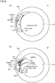
- Fig. 6 is a plan view for describing a manner of operation and an advantageous effect acquired by the optical diaphragm device 10 according to the embodiment 1.
- Fig. 6(a) shows a state (fully open state) where the aperture diameter of the diaphragm aperture is set to a maximum value
- Fig. 6(b) shows a state (minimum aperture state) where the aperture diameter of the diaphragm aperture is set to a minimum value.
- the light leakage prevention blade 200j further has the light leakage prevention blade extending portion 250 which extends toward the other side from the second fixing boss 220 (also see Fig. 3 ).
- the light leakage prevention blade extending portion 250 As shown in Fig. 6(b) , for example, even when the optical diaphragm device 10 is brought into a minimum aperture state, it is possible to make a portion of the diaphragm blade 100j+1 (#3) overlap with the light leakage prevention blade extending portion 250 of the light leakage prevention blade 200j.
- the optical diaphragm device 10 can maintain the overlapping order of the diaphragm blade 100 and the light leakage prevention blade 200.
- the set of the first fixing boss 120 and the first hole 401j is disposed at the position where the distance from the optical axis OA to the set of the first fixing boss 120 and the first hole 401j is shorter than the distance from the optical axis OA to the set of the second fixing boss 220 and the second hole 402j. That is, the set of the first fixing boss 120 and the first hole 401j is disposed more on the inner peripheral side than the set of the second fixing boss 220 and the second hole 402j.
- the position where the set of the first fixing boss 120 and the first hole 401j is disposed is, in other words, the position where the rotary shaft of the diaphragm blade 100 is disposed.
- a rotation angle of the diaphragm blade 100 which rotates between the position where the diaphragm blade 100 is in a fully open state and the position where the diaphragm blade 100 is in a minimum aperture state.
- the nearer the rotary shaft of the diaphragm blade 100 is disposed to the optical axis OA the larger the rotation angle becomes.
- driving of the diaphragm blade 100 is minimally affected by irregularities in manufacture in positions, sizes or the like of the first fixing boss 120, the first hole 401, the moving boss 130, and the first cam groove 330 of the drive ring 300 and the like.
- the diaphragm aperture with high accuracy as a whole by arranging the set of the first fixing boss 120 and the first hole 401j at a position where the distance from the optical axis OA to the set of the first fixing boss 120 and the first hole 401j is shorter than the distance from the optical axis OA to the set of the second fixing boss 220 and the second hole 402j, that is, by arranging the rotary shaft of the diaphragm blade 100 at the position closer to the optical axis OA.
- the length of the diaphragm blade 100 can be decreased by arranging the rotary shaft of the diaphragm blade 100 closer to the optical axis OA (by arranging the set of the first fixing boss 120 and the first hole 401j at the position closer to the optical axis OA than the position of the set of the second fixing boss 220 and the second hole 402j).
- the length of the diaphragm blade 100 By decreasing the length of the diaphragm blade 100, inertia of the diaphragm blade 100 during rotation can be decreased and hence, accuracy of rotation and velocity can be enhanced. Downsizing of the optical diaphragm device 10 can also be realized.
- the set of the first fixing boss 120 and the first hole 401j, and the set of the second fixing boss 220 and the second hole 402j are arranged on the same straight line extending in a radial direction (r direction) from the optical axis OA. That is, the optical axis OA, the set of the first fixing boss 120 and the first hole 401j, and the set of the second fixing boss 220 and the second hole 402j are arranged on the same straight line.
- an angle which the set of the first fixing boss and the first hole 401j and the set of the second fixing boss and the second hole 402j which form a pair occupies (an angle made by a line which connects the set of the first fixing boss and the first hole 401j with the optical axis OA and a line which connects the set of the second fixing boss and the second hole 402j with the optical axis OA) can be minimized. That is, such an occupied angle can be set to 0°.
- the occupied angle can be minimized and hence, it is possible to arrange the larger number of pairs each consisting of the set of the first fixing boss 120 and the first hole 401j and the set of the second fixing boss 220 and the second hole 402j around the optical axis OA whereby the degree of freedom in designing the optical diaphragm device can be enhanced.
- the optical diaphragm device which enables easy working and inspection of the optical diaphragm device 10.
- the first holes 401j and the second holes 402j are formed in the housing body 400 by working with reference to the optical axis OA
- the first holes 401j are formed by working and, thereafter, the second holes 402j are formed by working while changing a distance only in a radial direction (by shifting a working head in an r direction) without changing an angle with respect to the optical axis OA. Accordingly, working can be continued without performing a process of changing an angle. Substantially the same manner of operation and advantageous effects can be acquired also in the inspection of the optical diaphragm device.
- Recessed portion 114 formed by cutting out outer periphery of diaphragm blade 100
- a recessed portion 114 is formed on an outer profile 115 of the diaphragm blade 100 by cutting.
- the recessed portion 114 is formed so as to allow the moving boss 130' relating to the diaphragm blade 100j-1(see double-dashed chain line in Fig. 4 (a) ) and the light leakage prevention blade 200j-1(not shown in the drawing) which form the preceding pair to be disposed in the recessed portion 114 when the diaphragm blade 100 is moved to the position where the aperture diameter of the diaphragm aperture becomes maximum.
- a width of the diaphragm blade 100 is decided depending on designing of the optical diaphragm device.
- the outer profile 115 of the diaphragm blade 100 interferes with the moving boss relating to the diaphragm blade and the light leakage prevention blade which form another pair which is the neighboring pair in a plan-view layout.
- a design may be considered where the moving boss is disposed at the position which is further shifted in a radial direction(r direction) so as to move the moving boss away from the outer profile 115.
- the optical diaphragm device becomes large-sized by an amount that the moving boss is shifted.
- the recessed portion 114 is formed on the outer profile 115 of the diaphragm blade 100. Accordingly, it is possible to avoid the interference between the diaphragm blade 100 out of the diaphragm blade 100j and the light leakage prevention blade 200j which form a pair with the moving boss 130' relating to the diaphragm blade 100j-1 and the light leakage prevention blade 200j-1 (not shown in drawing) which form the preceding pair. As a result, large-sizing of the optical diaphragm device can be suppressed.
- the size of the recessed portion 114 formed on the diaphragm blade 100 be set to a size which prevents the formation of a gap between the diaphragm blade 100 and the recessed portion 114 of the diaphragm blade 100 which is disposed adjacently to the diaphragm blade 100 and forms the succeeding pair when the aperture diam-eter of the diaphragm aperture is throttled at maximum in cooperation with the plurality of diaphragm blades 100.
- the recessed portion 114 Assuming a case where the size of the recessed portion 114 is set large, when the aperture diameter of the diaphragm aperture is throttled, there is a possibility that a gap is formed between the diaphragm blade 100 and the recessed portion 114 of the diaphragm blade 100 which is disposed adjacently to the diaphragm blade 100 and hence, the recessed portion becomes a cause of a leakage of light. Further, in the case where the recessed portion 114 becomes a cause of a leakage of light, it is necessary to largely increase the size of the light leakage prevention blade 200 so as to shield the gap and hence, there is a possibility that such a configuration is not available due to the restriction imposed on the space.
- the first cam groove 330 is formed at an angle which is inclined in a direction away from the optical axis OA toward a diaphragm rotational direction ROT with respect to a circumferential direction about the optical axis OA.
- a direction along which the diaphragm blade 100 is moved toward the optical axis OA by moving the first cam groove 330 due to the rotation of the drive ring 300 is assumed as the diaphragm rotational direction ROT.
- the first cam grooves 330 having such inclination are formed. Accordingly, when the drive ring 300 is rotated in the diaphragm rotational directional ROT, the position of the moving boss 130 inserted into the first cam groove 330 formed in the drive ring 300 is moved in a direction that the moving boss 130 approaches the optical axis OA. Due to such a configuration, a length of the first cam groove 330 can be shortened compared to the configuration where the inclination direction of the first cam groove 330 is set in an opposite manner.
- the number of first cam grooves 330 can be easily increased.
- an angle made by the second cam groove 230 and the circumferential direction is set larger than an angle made by the first cam groove 330 and the circumferential direction. That is, the second cam groove 230 makes a large (deep) angle with respect to the circumferential direction, and the first cam groove 330 makes a small (shallow) angle with respect to the circumferential direction.
- an extension length of the second cam groove 230 is shorter than an extension length of the first cam groove 330.
- the second cam groove 230 having a required minimum length and hence, the light leakage prevention blade 200 can also be formed in a compact shape. Such structure contributes to downsizing of the optical diaphragm device 10.
- the diaphragm blade 100j out of "the diaphragm blade 100j and the light leakage prevention blade 200j which form the pair” the light leakage prevention blade 200j out of "the diaphragm blade 100j and the light leakage prevention blade 200j which form the pair”
- the diaphragm blade 100j+1 out of "the diaphragm blade 100j+1 and the light leakage prevention blade 200j+1 which form the succeeding pair” positioned adjacently to the diaphragm blade 100j and the light leakage prevention blade 200j which form the pair
- the light leakage prevention blade 200j+1 out of "the diaphragm blade 100j+1 and the light leakage prevention blade 200j+1 which form the succeeding pair” are arranged in an overlapping manner in this order (see Fig. 3 , Fig. 6 and the like).
- the optical diaphragm device 10 is formed such that in viewing the optical diaphragm device along the optical axis OA, a portion of the outer profile 115 of the diaphragm blade 100j+1 out of "the diaphragm blade 100j+1 and the light leakage prevention blade 200j+1 which form the succeeding pair" always overlaps with the light leakage prevention blade 200j out of "the diaphragm blade 100j and the light leakage prevention blade 200j which form the pair".
- the outer profile 115 of the diaphragm blade 100 "always overlaps with" the light leakage prevention blade 200. That is, in a case where the optical diaphragm device is in a fully open state, a portion of the outer profile 115 on a distal end side of a diaphragm blade 100j+1 side (a side opposite to the first fixing boss 120) overlaps with the light leakage prevention blade 200j. In a case where the optical diaphragm device is in a minimum aperture state, a portion of the outer profile 115 on a first fixing boss 120 side of the diaphragm blade 100j+1 overlaps with the light leakage prevention blade 200j. Also in an intermediate state between the fully open state and the minimum aperture state, the diaphragm blade 100 overlaps with the light leakage prevention blade 200.
- outer profile 115 of the diaphragm blade 100 refers to a profile of the diaphragm blade 100 on a side remotest in distance from the optical axis OA with respect to the profile of the diaphragm blade 100 when the diaphragm blade 100 is viewed along the optical axis OA in a state where the aperture diameter of the diaphragm aperture is set to a maximum value (fully open state).
- the optical diaphragm device 10 is formed such that in a state where the aperture diameter AD of the diaphragm aperture assumes a minimum value, a portion of the outer profile 115 of the diaphragm blade 100j+1 overlaps with the light leakage prevention blade extending portion 250 of the light leakage prevention blade 200j out of "the diaphragm blade 100j and the light leakage prevention blade 200j which form the pair" while maintaining the overlapping order (see Fig. 6(b) ).
- the portion of the outer profile 115 of the diaphragm blade 100j+1 out of “the diaphragm blade 100j+1 and the light leakage prevention blade 200j+1 which form the succeeding pair" always overlaps with the light leakage prevention blade 200j out of "the diaphragm blade 100j and the light leakage prevention blade 200j which form the pair”.
- the outer profile 115 of the diaphragm blade 100j+1 falls within a range of the light leakage prevention blade 200j and hence, it is possible to prevent the occurrence of a case where the diaphragm blade 100j+1 falls out from the light leakage prevention blade 200j and is disposed on the same stage as the light leakage prevention blade 200j or the occurrence of a case where the diaphragm blade 100j+1 sinks below the light leakage prevention blade 200j thus causing an exchange of the overlapping order of the blades.
- the portion of the outer profile 115 of the diaphragm blade 100j+1 overlaps with the light leakage prevention blade extending portion 250 of the light leakage prevention blade 200j out of "the diaphragm blade 100j and the light leakage prevention blade 200j which form the pair".
- the outer profile 115 of the diaphragm blade 100j+1 falls within a range of the light leakage prevention blade extending portion 250 of the light leakage prevention blade 200j and hence, it is possible to prevent the occurrence of a case where the diaphragm blade 100j+1 falls out from the light leakage prevention blade 200j and is disposed on the same stage as the light leakage prevention blade 200j or the occurrence of a case where the diaphragm blade 100j+1 sinks below the light leakage prevention blade 200j thus causing an exchange of the overlapping order of the blades.
- the optical diaphragm device 10 can maintain the overlapping order of the diaphragm blade 100 and the light leakage prevention blade 200.
- Fig. 7 is a perspective view for describing a main part of the optical diaphragm device 10a according to the embodiment 2.
- the diaphragm blade 100j and the light leakage prevention blade 200j which form the pair the diaphragm blade 100j+1 and the light leakage prevention blade 200j+1 which form the succeeding pair positioned adjacently to "the diaphragm blade 100j and the light leakage prevention blade 200j which form the pair” and the intermediate blade 280j are shown.
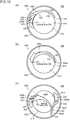
- Fig. 8 is a plan view for describing a manner of operation and an advantageous effect acquired by the optical diaphragm device 10a according to the embodiment 2.
- Fig. 8(a) shows a state (fully open state) where an aperture diameter of a diaphragm aperture is set to a maximum value
- Fig. 8(b) shows a state (minimum aperture state) where the aperture diameter of the diaphragm aperture is set to a minimum value.
- the optical diaphragm device 10a according to the embodiment 2 has basically substantially the same configuration as the optical diaphragm device 10 according to the embodiment 1. However, the optical diaphragm device 10a according to the embodiment 2 differs from the optical diaphragm device 10 according to the embodiment 1 with respect to a point that the optical diaphragm device 10a includes an intermediate blade 280 in place of or in addition to a light leakage prevention blade extending portion 250.
- the optical diaphragm device 10a further includes an intermediate blade 280j disposed between the light leakage prevention blade 200j and the diaphragm blade 100j+1 ("j" is a variable used as an index, and takes an integer of 1 or more.
- j is a variable used as an index, and takes an integer of 1 or more.
- the intermediate blade 280j is simply expressed as the intermediate blade 280, or the description is made by omitting affixing the variable j).
- intermediate means an intermediate as viewed from a viewpoint of the order of overlapping the blades along the second direction.
- the intermediate blade 280 may be made of any material, and it is preferable that the intermediate blade 280 be made of a slippery material which allows the intermediate blade 280 to mate with and to smoothly slide on other constitutional elements (the diaphragm blade 100 and the light leakage prevention blade 200).
- the intermediate blade 280 is fixed to the housing body 400 in a state where the intermediate blade 280 does not interfere with the movement of the diaphragm blade 100 and the movement of the light leakage prevention blade 200.
- the intermediate blade 280 falls within a width of the housing body 400 as viewed along an optical axis OA when at least the optical diaphragm device 10a is in a fully open state. During a process where the diaphragm aperture is advancing in the closing direction, the intermediate blade 280 may go beyond the width of the housing body 400 so long as the intermediate blade 280 does not obstruct the aperture diameter. However, it is more preferable that the intermediate blade 280 is fixed to the housing body 400.
- a loose hole 281 having an inner diameter sufficiently large compared to a diameter of the first fixing boss 120 is formed in the third planar plate 282 of the intermediate blade 280 at a position corresponding to the first fixing boss 120 of the diaphragm blade 100j+1, and a third cam groove 285 having the same shape as a trajectory of the moving boss 130 is formed in the third planar plate 282 of the intermediate blade 280 such that the shape of the third cam groove 285 corresponds to a curved line/straight line which a moving path (trajectory) of the moving boss 130 of the diaphragm blade 100j draws.
- one end of the intermediate blade 280 is fixed to the housing body 400 together with the diaphragm blade 100j+1 using the first fixing boss 120 of the diaphragm blade 100j+1, the loose hole 281 of the intermediate blade 280, and the first hole 401j+1 of the housing body 400.
- the moving boss 130 of the diaphragm blade 100j is inserted into not only the second cam groove 230 of the light leakage prevention blade 200j but also the third cam groove 285 of the intermediate blade 280. Since the third cam groove 285 of the intermediate blade 280 is restricted by the above-mentioned moving boss 130, the other end of the intermediate blade 280 is also substantially fixed to the housing body 400.
- the intermediate blade 280 can be substantially fixed to the housing body 400 by making use of the existing constitutional elements (the first fixing boss 120 and the moving boss 130) without using an additional boss, an additional screw or the like.
- the diaphragm blade 100j out of "the diaphragm blade 100j and the light leakage prevention blade 200j which form the pair” the light leakage prevention blade 200j out of "the diaphragm blade 100j and the light leakage prevention blade 200j which form the pair"
- the light leakage prevention blade 200j+1 out of "the diaphragm blade 100j+1 and the light leakage prevention blade 200j+1 which form the succeeding pair” are arranged in an overlapping manner in the upward direction in this order.
- the optical diaphragm device 10a is formed such that in viewing the optical diaphragm device 10a along the optical axis OA, the intermediate blade 280j and the light leakage prevention blade 200j out of "the diaphragm blade 100j and the light leakage prevention blade 200j which form the pair" always overlap with each other. Further, the optical diaphragm device 10a is formed such that the intermediate blade 280j and the diaphragm blade 100j+1 out of "the diaphragm blade 100j+1 and the light leakage prevention blade 200j+1 which form the succeeding pair" always overlap with each other (see also Fig. 8(a) and Fig. 8(b) ).
- the optical diaphragm device 10a according to the embodiment 2 also, substantially in the same manner, includes the diaphragm blade 100, the light leakage prevention blade 200 having the second cam groove 230, the drive ring 300, the housing body 400 and the like of the embodiment 1. Accordingly, the description of these constitutional elements in the embodiment 1 is used in the embodiment 2, and the description of these constitutional element is omitted in the embodiment 2.
- the optical diaphragm device 10a of the embodiment 2 further includes the intermediate blade 280 disposed between the light leakage prevention blade 200j and the diaphragm blade 100j+1, and the optical diaphragm device 10a is formed such that the intermediate blade 280 and the light leakage prevention blade 200j out of "the diaphragm blade 100j and the light leakage prevention blade 200j which form the pair" always overlap with each other.
- the intermediate blade 280 As shown in Fig. 8(b) , for example, even when the optical diaphragm device 10a is brought into a minimum aperture state, the light leakage prevention blade 200j (#2) out of "the diaphragm blade 100j (#1) and the light leakage prevention blade 200j (#2) which form the pair" and the intermediate blade 280(#3) which is disposed above the light leakage prevention blade 200j (#2) overlap with each other in a third region RG3.
- the optical diaphragm device 10a is formed such that the intermediate blade 280j (#3) and the diaphragm blade 100j+1(#4) out of "the diaphragm blade 100j+1(#4) and the light leakage prevention blade 200j+1 which form the succeeding pair" always overlap with each other.
- the intermediate blade 280j (#3) and the diaphragm blade 100j+1(#4) which is disposed on the stage above the intermediate blade 280j (#3) overlap with each other in a fourth region RG4 (see Fig. 8(b) ).
- a region where the diaphragm blade 100j+1(#4) and the intermediate blade 280j (#3) overlap with each other is ensured and hence, the diaphragm blade 100j+1(#4) is inevitably disposed on a stage above the intermediate blade 280j (#3).
- the optical diaphragm device 10a of the embodiment 2 can maintain the overlapping order of diaphragm blade 100 and light leakage prevention blade 200.
- the optical diaphragm device 10a according to the embodiment 2 has substantially the same configuration as the optical diaphragm device 10 according to the embodiment 1 except for the point that the optical diaphragm device 10a includes the intermediate blade 280 in place of or in addition to the light leakage prevention blade extending portion 250. Accordingly, the optical diaphragm devices 10a according to the embodiment 2 acquires the corresponding advantageous effects found amongst all advantageous effects which the optical diaphragm device 10 according to the embodiment 1 acquires.
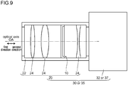
- Fig. 9 is a schematic view for describing a lens barrel 20 according to an embodiment 3 and an imaging device 30 or a projection device 35 according to an embodiment 4.
- the optical diaphragm device 10 according to the embodiment 1 and a plurality of lenses 24 are housed.
- the lens barrel 20 according to the embodiment 3 includes the optical diaphragm device 10 according to the embodiment 1 and hence, it is possible to provide the lens barrel 20 where large-sizing of the lens barrel 20 can be suppressed, and a favorable imaging state can be acquired.
- the optical diaphragm device 10a according to the embodiment 2 can be adopted in place of the optical diaphragm device 10 according to the embodiment 1.
- an imaging device 30 according to the embodiment 4 includes: the optical diaphragm device 10 according to the embodiment 1 or the lens barrel 20 according to the embodiment 3, and an imaging device body 32.
- the imaging device 30 according to the embodiment 4 is applicable to a camera or the like, for example.
- a projection device 35 according to the embodiment 4 includes the optical diaphragm device 10 according to the embodiment 1 or the lens barrel 20 according to the embodiment 3; and a projection device body 37.
- the projection device 35 according to the embodiment 4 is applicable to a projector or the like, for example.
- the imaging device 30 or the projection device 35 according to the embodiment 4 includes: the optical diaphragm device 10 according to the embodiment 1 or the lens barrel 20 according to the embodiment 3. With such a configuration, large-sizing of the imaging device 30 or the projection device 35 can be suppressed. It is also possible to provide the imaging device 30 where a favorable imaging state can be acquired, or the projection device 35 where a favorable projection state can be acquired.
- the optical diaphragm device 10a according to the embodiment 2 may be applicable in place of the optical diaphragm device 10 according to the embodiment 1.
- Fig. 13 is a plan view for describing a fixing method of fixing an intermediate blade 280a according to a modification 4 and a fixing method of fixing an intermediate blade 280b according to the modification 5.
- Fig. 13(a) shows the intermediate blade 280a according to the modification 4
- Fig. 13(b) shows the intermediate blade 280b according to the modification 5 respectively.
- Fig. 13 only the intermediate blade and the housing body necessary for the description are shown, and other diaphragm blades, light leakage prevention blades and the like are omitted from the drawing.
- a third fixing boss 283 is formed on one side of a third planar plate 282a of the intermediate blade 280a, and a third cam groove 285 is formed in the third planar plate 282a of the intermediate blade 280a such that the third cam groove 285 corresponds to a curved line/straight line which a moving path (trajectory) of the moving boss 130 of the diaphragm blade 100 positioned on a stage below the intermediate blade 280a draws.
- a third hole 403j is formed in a housing body 400a.
- a third fixing boss 283 is inserted into the third hole 403j, and a moving boss 130 of the diaphragm blade 100 which is positioned on a stage below the intermediate blade 280a is inserted into the third cam groove 285.
- the intermediate blade 280a can be substantially fixed to the housing body 400a (modification 4).
- a third fixing boss 283 and a fourth fixing boss 284 are formed on a third planar plate 282b of the intermediate blade 280b.
- a third hole 403j and a fourth hole 404j are formed also in a housing body 400b.
- the third fixing boss 283 is inserted into the third hole 403j
- the fourth fixing boss 284 is inserted into the fourth hole 404j and hence, the intermediate blade 280b can be fixed to the housing body 400b (modification 5).
- the number of fixing bosses may be three or more.
- the intermediate blade 280b can be fixed without introducing a third cam groove and hence, it is unnecessary to perform the restriction (substantially fixing) of the intermediate blade by the moving boss of other diaphragm blade by way of the third cam groove whereby a load imposed on an operation of other diaphragm blade can be reduced. Accordingly, it is possible to expect the realization of the more smooth driving of the blades while achieving further energy saving.
Landscapes
- Physics & Mathematics (AREA)
- General Physics & Mathematics (AREA)
- Optics & Photonics (AREA)
- Diaphragms For Cameras (AREA)
Applications Claiming Priority (2)
| Application Number | Priority Date | Filing Date | Title |
|---|---|---|---|
| JP2017244881A JP6892121B2 (ja) | 2017-12-21 | 2017-12-21 | 絞り装置、レンズ鏡筒及び撮像装置又は投影装置 |
| PCT/JP2018/044646 WO2019124071A1 (ja) | 2017-12-21 | 2018-12-05 | 絞り装置、レンズ鏡筒及び撮像装置又は投影装置 |
Publications (4)
| Publication Number | Publication Date |
|---|---|
| EP3731012A1 true EP3731012A1 (de) | 2020-10-28 |
| EP3731012A4 EP3731012A4 (de) | 2021-07-14 |
| EP3731012C0 EP3731012C0 (de) | 2023-11-22 |
| EP3731012B1 EP3731012B1 (de) | 2023-11-22 |
Family
ID=66994614
Family Applications (1)
| Application Number | Title | Priority Date | Filing Date |
|---|---|---|---|
| EP18891884.1A Active EP3731012B1 (de) | 2017-12-21 | 2018-12-05 | Optische blendenvorrichtung, objektivtubus und bildaufnahmevorrichtung oder projektionsvorrichtung |
Country Status (5)
| Country | Link |
|---|---|
| US (1) | US11500134B2 (de) |
| EP (1) | EP3731012B1 (de) |
| JP (1) | JP6892121B2 (de) |
| CN (1) | CN111587400B (de) |
| WO (1) | WO2019124071A1 (de) |
Families Citing this family (3)
| Publication number | Priority date | Publication date | Assignee | Title |
|---|---|---|---|---|
| TWI708113B (zh) * | 2019-07-10 | 2020-10-21 | 致能機電工業股份有限公司 | 光圈片轉移裝置 |
| EP4137886B1 (de) * | 2021-04-14 | 2025-08-06 | Beijing Xiaomi Mobile Software Co., Ltd. | Blendenvorrichtung, kameramodul mit blendenvorrichtung und elektronische vorrichtung |
| CN115185139B (zh) * | 2022-06-09 | 2023-10-27 | 新思考电机有限公司 | 光圈组件及摄像模组 |
Family Cites Families (20)
| Publication number | Priority date | Publication date | Assignee | Title |
|---|---|---|---|---|
| JPS4326691B1 (de) * | 1961-09-15 | 1968-11-16 | ||
| JPH05113591A (ja) | 1991-10-21 | 1993-05-07 | Nikon Corp | 絞り機構 |
| JP4208619B2 (ja) * | 2003-03-26 | 2009-01-14 | キヤノン株式会社 | 絞り機構、絞り機構を有するレンズ装置 |
| US7553094B2 (en) * | 2004-07-01 | 2009-06-30 | Canon Kabushiki Kaisha | Light quantity adjusting apparatus, image pickup apparatus and optical apparatus |
| JP4003791B2 (ja) * | 2005-10-19 | 2007-11-07 | セイコーエプソン株式会社 | プロジェクタ |
| CN201097064Y (zh) * | 2007-10-16 | 2008-08-06 | 微太科技股份有限公司 | 摄影镜头的光圈结构 |
| JP5330107B2 (ja) * | 2009-06-03 | 2013-10-30 | オリンパスイメージング株式会社 | 絞り装置 |
| JP5464939B2 (ja) * | 2009-08-06 | 2014-04-09 | キヤノン株式会社 | 光学機器 |
| JP5461278B2 (ja) * | 2010-03-31 | 2014-04-02 | 日本電産コパル株式会社 | カメラ用絞り装置 |
| JP5558236B2 (ja) * | 2010-07-08 | 2014-07-23 | オリンパスイメージング株式会社 | レンズ鏡筒 |
| JP5604246B2 (ja) * | 2010-09-28 | 2014-10-08 | 日本電産コパル株式会社 | カメラ用羽根駆動装置 |
| US8654455B2 (en) * | 2011-05-10 | 2014-02-18 | Nisca Corporation | Light quantity adjustment apparatus, lens unit and optical apparatus provided with the same |
| JP6172893B2 (ja) * | 2012-04-05 | 2017-08-02 | 株式会社nittoh | 反射面を支持する装置およびプロジェクタ |
| JP6172955B2 (ja) * | 2013-01-30 | 2017-08-02 | キヤノン株式会社 | 光量調整装置、レンズ鏡筒および撮像装置 |
| CN203587886U (zh) * | 2013-12-17 | 2014-05-07 | 中山联合光电科技有限公司 | 一种用于步进光圈的叶片 |
| JP6494016B2 (ja) * | 2014-11-18 | 2019-04-03 | セイコープレシジョン株式会社 | 絞り装置および光学機器 |
| JP6924009B2 (ja) * | 2015-09-16 | 2021-08-25 | キヤノン電子株式会社 | 羽根駆動装置及び光学装置 |
| JP2017078789A (ja) * | 2015-10-21 | 2017-04-27 | 日本電産コパル株式会社 | カメラ用絞り機構、及びカメラ |
| JP6810443B2 (ja) * | 2016-06-22 | 2021-01-06 | 株式会社nittoh | 絞り装置、レンズ鏡筒及び撮像装置又は投影装置 |
| EP3553599B1 (de) * | 2016-12-09 | 2022-09-21 | Nittoh Inc. | Membranvorrichtung, objektivtubus und bildgebungsvorrichtung oder projektionsvorrichtung |
-
2017
- 2017-12-21 JP JP2017244881A patent/JP6892121B2/ja active Active
-
2018
- 2018-12-05 US US16/955,049 patent/US11500134B2/en active Active
- 2018-12-05 WO PCT/JP2018/044646 patent/WO2019124071A1/ja not_active Ceased
- 2018-12-05 CN CN201880080544.XA patent/CN111587400B/zh active Active
- 2018-12-05 EP EP18891884.1A patent/EP3731012B1/de active Active
Also Published As
| Publication number | Publication date |
|---|---|
| US20200379148A1 (en) | 2020-12-03 |
| WO2019124071A1 (ja) | 2019-06-27 |
| JP2019113602A (ja) | 2019-07-11 |
| EP3731012C0 (de) | 2023-11-22 |
| JP6892121B2 (ja) | 2021-06-18 |
| US11500134B2 (en) | 2022-11-15 |
| CN111587400B (zh) | 2021-10-29 |
| EP3731012A4 (de) | 2021-07-14 |
| CN111587400A (zh) | 2020-08-25 |
| EP3731012B1 (de) | 2023-11-22 |
Similar Documents
| Publication | Publication Date | Title |
|---|---|---|
| US10884317B2 (en) | Optical diaphragm device, lens barrel and imaging device or projection device | |
| US10503051B2 (en) | Optical diaphragm device, lens barrel, and imaging device or projection device | |
| EP3731012B1 (de) | Optische blendenvorrichtung, objektivtubus und bildaufnahmevorrichtung oder projektionsvorrichtung | |
| US10901172B2 (en) | Camera lens assembly | |
| JP6624786B2 (ja) | 絞り装置及びそれを有するレンズ装置及び撮像装置 | |
| CN108027546A (zh) | 叶片驱动装置和光学装置 | |
| US20170192337A1 (en) | Light amount adjusting device | |
| JP2011215319A (ja) | カメラ用絞り装置 | |
| JP2019090889A (ja) | 絞り装置、レンズ装置および撮像装置 | |
| EP3112912B1 (de) | Objektivtubus und optisches instrument | |
| WO2012102005A1 (ja) | レンズ鏡筒 | |
| WO2012102007A1 (ja) | レンズ鏡筒 | |
| JP2014071144A (ja) | 絞り装置及び撮像装置 | |
| JP5958782B2 (ja) | レンズ鏡筒 | |
| JP2016102830A (ja) | 羽根駆動装置及び撮像装置 | |
| US20190265431A1 (en) | Lens barrel and imaging device equipped with same | |
| US20160161829A1 (en) | Stop mechanism, lens apparatus using the same, and image pickup apparatus | |
| WO2012102004A1 (ja) | レンズ鏡筒 | |
| JP2018189862A (ja) | レンズ鏡筒及び撮像装置 | |
| CN102681137B (zh) | 固定凸轮筒 | |
| JP2020012999A (ja) | 絞り装置、レンズ装置、および撮像装置 | |
| JP2007127990A (ja) | レンズ鏡筒 |
Legal Events
| Date | Code | Title | Description |
|---|---|---|---|
| STAA | Information on the status of an ep patent application or granted ep patent |
Free format text: STATUS: THE INTERNATIONAL PUBLICATION HAS BEEN MADE |
|
| PUAI | Public reference made under article 153(3) epc to a published international application that has entered the european phase |
Free format text: ORIGINAL CODE: 0009012 |
|
| STAA | Information on the status of an ep patent application or granted ep patent |
Free format text: STATUS: REQUEST FOR EXAMINATION WAS MADE |
|
| 17P | Request for examination filed |
Effective date: 20200623 |
|
| AK | Designated contracting states |
Kind code of ref document: A1 Designated state(s): AL AT BE BG CH CY CZ DE DK EE ES FI FR GB GR HR HU IE IS IT LI LT LU LV MC MK MT NL NO PL PT RO RS SE SI SK SM TR |
|
| AX | Request for extension of the european patent |
Extension state: BA ME |
|
| DAV | Request for validation of the european patent (deleted) | ||
| DAX | Request for extension of the european patent (deleted) | ||
| A4 | Supplementary search report drawn up and despatched |
Effective date: 20210615 |
|
| RIC1 | Information provided on ipc code assigned before grant |
Ipc: G03B 9/06 20210101AFI20210609BHEP Ipc: G03B 7/00 20210101ALI20210609BHEP |
|
| GRAP | Despatch of communication of intention to grant a patent |
Free format text: ORIGINAL CODE: EPIDOSNIGR1 |
|
| STAA | Information on the status of an ep patent application or granted ep patent |
Free format text: STATUS: GRANT OF PATENT IS INTENDED |
|
| RIC1 | Information provided on ipc code assigned before grant |
Ipc: G03B 9/06 20060101AFI20230628BHEP |
|
| INTG | Intention to grant announced |
Effective date: 20230721 |
|
| GRAS | Grant fee paid |
Free format text: ORIGINAL CODE: EPIDOSNIGR3 |
|
| GRAA | (expected) grant |
Free format text: ORIGINAL CODE: 0009210 |
|
| STAA | Information on the status of an ep patent application or granted ep patent |
Free format text: STATUS: THE PATENT HAS BEEN GRANTED |
|
| AK | Designated contracting states |
Kind code of ref document: B1 Designated state(s): AL AT BE BG CH CY CZ DE DK EE ES FI FR GB GR HR HU IE IS IT LI LT LU LV MC MK MT NL NO PL PT RO RS SE SI SK SM TR |
|
| REG | Reference to a national code |
Ref country code: GB Ref legal event code: FG4D |
|
| REG | Reference to a national code |
Ref country code: CH Ref legal event code: EP Ref country code: DE Ref legal event code: R096 Ref document number: 602018061632 Country of ref document: DE |
|
| REG | Reference to a national code |
Ref country code: IE Ref legal event code: FG4D |
|
| U01 | Request for unitary effect filed |
Effective date: 20231123 |
|
| U07 | Unitary effect registered |
Designated state(s): AT BE BG DE DK EE FI FR IT LT LU LV MT NL PT SE SI Effective date: 20231129 |
|
| U20 | Renewal fee for the european patent with unitary effect paid |
Year of fee payment: 6 Effective date: 20240124 |
|
| PG25 | Lapsed in a contracting state [announced via postgrant information from national office to epo] |
Ref country code: GR Free format text: LAPSE BECAUSE OF FAILURE TO SUBMIT A TRANSLATION OF THE DESCRIPTION OR TO PAY THE FEE WITHIN THE PRESCRIBED TIME-LIMIT Effective date: 20240223 |
|
| PG25 | Lapsed in a contracting state [announced via postgrant information from national office to epo] |
Ref country code: IS Free format text: LAPSE BECAUSE OF FAILURE TO SUBMIT A TRANSLATION OF THE DESCRIPTION OR TO PAY THE FEE WITHIN THE PRESCRIBED TIME-LIMIT Effective date: 20240322 |
|
| PG25 | Lapsed in a contracting state [announced via postgrant information from national office to epo] |
Ref country code: ES Free format text: LAPSE BECAUSE OF FAILURE TO SUBMIT A TRANSLATION OF THE DESCRIPTION OR TO PAY THE FEE WITHIN THE PRESCRIBED TIME-LIMIT Effective date: 20231122 |
|
| PG25 | Lapsed in a contracting state [announced via postgrant information from national office to epo] |
Ref country code: IS Free format text: LAPSE BECAUSE OF FAILURE TO SUBMIT A TRANSLATION OF THE DESCRIPTION OR TO PAY THE FEE WITHIN THE PRESCRIBED TIME-LIMIT Effective date: 20240322 Ref country code: GR Free format text: LAPSE BECAUSE OF FAILURE TO SUBMIT A TRANSLATION OF THE DESCRIPTION OR TO PAY THE FEE WITHIN THE PRESCRIBED TIME-LIMIT Effective date: 20240223 Ref country code: ES Free format text: LAPSE BECAUSE OF FAILURE TO SUBMIT A TRANSLATION OF THE DESCRIPTION OR TO PAY THE FEE WITHIN THE PRESCRIBED TIME-LIMIT Effective date: 20231122 |
|
| PG25 | Lapsed in a contracting state [announced via postgrant information from national office to epo] |
Ref country code: RS Free format text: LAPSE BECAUSE OF FAILURE TO SUBMIT A TRANSLATION OF THE DESCRIPTION OR TO PAY THE FEE WITHIN THE PRESCRIBED TIME-LIMIT Effective date: 20231122 Ref country code: PL Free format text: LAPSE BECAUSE OF FAILURE TO SUBMIT A TRANSLATION OF THE DESCRIPTION OR TO PAY THE FEE WITHIN THE PRESCRIBED TIME-LIMIT Effective date: 20231122 Ref country code: NO Free format text: LAPSE BECAUSE OF FAILURE TO SUBMIT A TRANSLATION OF THE DESCRIPTION OR TO PAY THE FEE WITHIN THE PRESCRIBED TIME-LIMIT Effective date: 20240222 Ref country code: HR Free format text: LAPSE BECAUSE OF FAILURE TO SUBMIT A TRANSLATION OF THE DESCRIPTION OR TO PAY THE FEE WITHIN THE PRESCRIBED TIME-LIMIT Effective date: 20231122 |
|
| PG25 | Lapsed in a contracting state [announced via postgrant information from national office to epo] |
Ref country code: CZ Free format text: LAPSE BECAUSE OF FAILURE TO SUBMIT A TRANSLATION OF THE DESCRIPTION OR TO PAY THE FEE WITHIN THE PRESCRIBED TIME-LIMIT Effective date: 20231122 |
|
| PG25 | Lapsed in a contracting state [announced via postgrant information from national office to epo] |
Ref country code: SK Free format text: LAPSE BECAUSE OF FAILURE TO SUBMIT A TRANSLATION OF THE DESCRIPTION OR TO PAY THE FEE WITHIN THE PRESCRIBED TIME-LIMIT Effective date: 20231122 |
|
| PG25 | Lapsed in a contracting state [announced via postgrant information from national office to epo] |
Ref country code: SM Free format text: LAPSE BECAUSE OF FAILURE TO SUBMIT A TRANSLATION OF THE DESCRIPTION OR TO PAY THE FEE WITHIN THE PRESCRIBED TIME-LIMIT Effective date: 20231122 Ref country code: SK Free format text: LAPSE BECAUSE OF FAILURE TO SUBMIT A TRANSLATION OF THE DESCRIPTION OR TO PAY THE FEE WITHIN THE PRESCRIBED TIME-LIMIT Effective date: 20231122 Ref country code: RO Free format text: LAPSE BECAUSE OF FAILURE TO SUBMIT A TRANSLATION OF THE DESCRIPTION OR TO PAY THE FEE WITHIN THE PRESCRIBED TIME-LIMIT Effective date: 20231122 Ref country code: CZ Free format text: LAPSE BECAUSE OF FAILURE TO SUBMIT A TRANSLATION OF THE DESCRIPTION OR TO PAY THE FEE WITHIN THE PRESCRIBED TIME-LIMIT Effective date: 20231122 |
|
| REG | Reference to a national code |
Ref country code: CH Ref legal event code: PL |
|
| REG | Reference to a national code |
Ref country code: DE Ref legal event code: R097 Ref document number: 602018061632 Country of ref document: DE |
|
| PG25 | Lapsed in a contracting state [announced via postgrant information from national office to epo] |
Ref country code: MC Free format text: LAPSE BECAUSE OF FAILURE TO SUBMIT A TRANSLATION OF THE DESCRIPTION OR TO PAY THE FEE WITHIN THE PRESCRIBED TIME-LIMIT Effective date: 20231122 |
|
| PG25 | Lapsed in a contracting state [announced via postgrant information from national office to epo] |
Ref country code: MC Free format text: LAPSE BECAUSE OF FAILURE TO SUBMIT A TRANSLATION OF THE DESCRIPTION OR TO PAY THE FEE WITHIN THE PRESCRIBED TIME-LIMIT Effective date: 20231122 |
|
| PLBE | No opposition filed within time limit |
Free format text: ORIGINAL CODE: 0009261 |
|
| STAA | Information on the status of an ep patent application or granted ep patent |
Free format text: STATUS: NO OPPOSITION FILED WITHIN TIME LIMIT |
|
| REG | Reference to a national code |
Ref country code: IE Ref legal event code: MM4A |
|
| PG25 | Lapsed in a contracting state [announced via postgrant information from national office to epo] |
Ref country code: IE Free format text: LAPSE BECAUSE OF NON-PAYMENT OF DUE FEES Effective date: 20231205 |
|
| PG25 | Lapsed in a contracting state [announced via postgrant information from national office to epo] |
Ref country code: CH Free format text: LAPSE BECAUSE OF NON-PAYMENT OF DUE FEES Effective date: 20231231 |
|
| GBPC | Gb: european patent ceased through non-payment of renewal fee |
Effective date: 20240222 |
|
| 26N | No opposition filed |
Effective date: 20240823 |
|
| PG25 | Lapsed in a contracting state [announced via postgrant information from national office to epo] |
Ref country code: IE Free format text: LAPSE BECAUSE OF NON-PAYMENT OF DUE FEES Effective date: 20231205 Ref country code: CH Free format text: LAPSE BECAUSE OF NON-PAYMENT OF DUE FEES Effective date: 20231231 |
|
| PG25 | Lapsed in a contracting state [announced via postgrant information from national office to epo] |
Ref country code: GB Free format text: LAPSE BECAUSE OF NON-PAYMENT OF DUE FEES Effective date: 20240222 |
|
| PG25 | Lapsed in a contracting state [announced via postgrant information from national office to epo] |
Ref country code: GB Free format text: LAPSE BECAUSE OF NON-PAYMENT OF DUE FEES Effective date: 20240222 |
|
| U20 | Renewal fee for the european patent with unitary effect paid |
Year of fee payment: 7 Effective date: 20241227 |
|
| PG25 | Lapsed in a contracting state [announced via postgrant information from national office to epo] |
Ref country code: CY Free format text: LAPSE BECAUSE OF FAILURE TO SUBMIT A TRANSLATION OF THE DESCRIPTION OR TO PAY THE FEE WITHIN THE PRESCRIBED TIME-LIMIT; INVALID AB INITIO Effective date: 20181205 |
|
| PG25 | Lapsed in a contracting state [announced via postgrant information from national office to epo] |
Ref country code: HU Free format text: LAPSE BECAUSE OF FAILURE TO SUBMIT A TRANSLATION OF THE DESCRIPTION OR TO PAY THE FEE WITHIN THE PRESCRIBED TIME-LIMIT; INVALID AB INITIO Effective date: 20181205 |
|
| PG25 | Lapsed in a contracting state [announced via postgrant information from national office to epo] |
Ref country code: TR Free format text: LAPSE BECAUSE OF FAILURE TO SUBMIT A TRANSLATION OF THE DESCRIPTION OR TO PAY THE FEE WITHIN THE PRESCRIBED TIME-LIMIT Effective date: 20231122 |
|
| U20 | Renewal fee for the european patent with unitary effect paid |
Year of fee payment: 8 Effective date: 20251230 |