EP3731496B1 - Dispositif de traitement, réseau, procédé et programme informatique - Google Patents
Dispositif de traitement, réseau, procédé et programme informatique Download PDFInfo
- Publication number
- EP3731496B1 EP3731496B1 EP20161815.4A EP20161815A EP3731496B1 EP 3731496 B1 EP3731496 B1 EP 3731496B1 EP 20161815 A EP20161815 A EP 20161815A EP 3731496 B1 EP3731496 B1 EP 3731496B1
- Authority
- EP
- European Patent Office
- Prior art keywords
- network
- data
- process device
- virtual topology
- parameter
- Prior art date
- Legal status (The legal status is an assumption and is not a legal conclusion. Google has not performed a legal analysis and makes no representation as to the accuracy of the status listed.)
- Active
Links
Images
Classifications
-
- H—ELECTRICITY
- H04—ELECTRIC COMMUNICATION TECHNIQUE
- H04L—TRANSMISSION OF DIGITAL INFORMATION, e.g. TELEGRAPHIC COMMUNICATION
- H04L67/00—Network arrangements or protocols for supporting network services or applications
- H04L67/01—Protocols
- H04L67/12—Protocols specially adapted for proprietary or special-purpose networking environments, e.g. medical networks, sensor networks, networks in vehicles or remote metering networks
-
- H—ELECTRICITY
- H04—ELECTRIC COMMUNICATION TECHNIQUE
- H04L—TRANSMISSION OF DIGITAL INFORMATION, e.g. TELEGRAPHIC COMMUNICATION
- H04L12/00—Data switching networks
- H04L12/28—Data switching networks characterised by path configuration, e.g. LAN [Local Area Networks] or WAN [Wide Area Networks]
- H04L12/40—Bus networks
- H04L12/403—Bus networks with centralised control, e.g. polling
-
- H—ELECTRICITY
- H04—ELECTRIC COMMUNICATION TECHNIQUE
- H04L—TRANSMISSION OF DIGITAL INFORMATION, e.g. TELEGRAPHIC COMMUNICATION
- H04L41/00—Arrangements for maintenance, administration or management of data switching networks, e.g. of packet switching networks
- H04L41/12—Discovery or management of network topologies
- H04L41/122—Discovery or management of network topologies of virtualised topologies, e.g. software-defined networks [SDN] or network function virtualisation [NFV]
-
- H—ELECTRICITY
- H04—ELECTRIC COMMUNICATION TECHNIQUE
- H04L—TRANSMISSION OF DIGITAL INFORMATION, e.g. TELEGRAPHIC COMMUNICATION
- H04L47/00—Traffic control in data switching networks
- H04L47/10—Flow control; Congestion control
- H04L47/28—Flow control; Congestion control in relation to timing considerations
Definitions
- a process device for carrying out a sub-step in a production plant wherein the process device has a network module for establishing a network connection and a memory module.
- Manufacturing plants often include a number of process devices, with the process devices carrying out partial steps of a production process.
- Process devices are, for example, modules such as transport devices, conveyor belts, drilling stations or mechanical work stations. Manufacturing plants must be designed to be adaptable in the course of frequently changing products and increasingly faster product cycles. To this end, process devices must, for example, carry out the production steps in a different order and/or in a different way.
- the publication EN 10 2005 061 155 A1 describes a communication structure with a communication controller which has a synchronization unit and a first interface and a second interface, wherein for data exchange the first interface is connected by means of a first connection and the second interface is connected to a communication system which has at least one further participant by means of a second connection, wherein the first interface and the second interface of the communication controller have a variable functionality.
- Time-Sensitive Networking A Technical Introduction White Paper
- Time-Sensitive Networking A Technical Introduction
- URL https://www.cisco.com/c/dam/en/us/solutions/collateral/industry-solutions/white-paper-c11-738950.pdf (accessed 19.04.2021 ))
- a process device for carrying out a partial step in a production plant with the features of claim 1 is proposed. Furthermore, a network with a network switch, a method for operating a network, a computer program and a storage medium are proposed. Preferred and/or advantageous embodiments of the invention emerge from the subclaims, the description and the attached figures.
- a process device for carrying out a partial step in a production plant comprises in particular a plurality of process devices.
- the process device is designed, for example, to carry out a mechanical step, a processing step, a measuring step and/or an electrical step on an object or component.
- the process device forms a transport device, a conveyor belt, a drilling station, a work station, in particular a mechanical work station, or a measuring station.
- the production plant can be arranged in a production room, for example a factory or factory section, wherein the process devices can be arranged in this room.
- the process devices interact with one another and/or can interact with one another.
- a part, in particular a component can be manufactured or processed in the production plant.
- the production plant is designed to be adaptable in order to be able to manufacture different products.
- the production plant is designed so that the process devices carry out the production steps in a different order and/or in another way.
- the production plant is designed so that the process devices can be arranged physically differently, wherein the arrangement of the process devices is combined into networks and/or network topologies.
- the process device has a network module for establishing a time-sensitive networking connection.
- the network module can be designed as a hardware or software module.
- the process device comprises network interfaces for connecting to another process device and/or a network switch.
- the connection can be designed as a wired connection.
- the time-sensitive networking connection is designed as a real-time connection so that the process devices can be operated with a low latency and, in particular, production steps can be carried out with great temporal accuracy.
- Time-sensitive networking is also referred to as TSN for short.
- the TSN connection can be used to implement real-time capability of the process device and/or the TSN connection.
- the TSN connection is based on an extended standard of Ethernet networks.
- the standards and/or the TSN connection include time synchronization, scheduling and/or traffic shaping.
- the TSN standard and/or the TSN connection includes, for example, a mechanism for path search and/or reservation of performance capacities to avoid packet loss.
- the time-sensitive networking connection can exist and/or be established between the process device and/or at least one other or several process devices. Alternatively and/or additionally, the time-sensitive networking connection can be formed between the process device and a network switch.
- the process device comprises a memory module.
- the memory module is designed, for example, as a memory chip.
- the memory module can be part of a computer module and/or processor module.
- the memory module comprises management shell data, in particular management shell data is stored in the memory module.
- An administration shell is understood, for example, to be a digital representation of the process device.
- the administration shell is designed to describe the technical functionalities of the process device and/or comprises a model of the process device.
- Administration shell data is understood, in particular, to be the data that is used and/or required to describe the process device and/or functionality of the process device.
- the administration shell data can also comprise data for operating and/or controlling the process device.
- the administration shell data includes virtual topology data (data of a virtual topology).
- the virtual topology data is used to set up, operate, define and/or change software-defined networking (software-defined network or software-defined networking).
- the time-sensitive networking connection is designed to implement software-defined networking.
- Software-defined networking is understood to mean, for example, the setting up of a network, in particular comprising several process devices that form and/or abstract a virtual network based on software and based on a physical network.
- Software-defined networking is used to define and/or set up a virtual topology.
- a virtual topology is understood to mean a network and/or the topology of the network, which does not necessarily correspond to the set up and/or topology of the physical connections.
- a network can have a first topology, for example a ring or star, where the first topology is the actual cabling of the components, and a different topology than the first can be operated and/or implemented using software-defined networking.
- the virtual topology data includes in particular the data required to set up and operate the software-defined networking.
- the invention is based on the idea of providing a process device for a production plant that is real-time capable and in particular supports time-sensitive networking.
- This can be used to implement virtual topologies within a software-defined network.
- This can be used, for example, to achieve a versatile production plant, since no unnecessary physical cabling and/or implementation of the actual underlying physical network is necessary, since different topologies within the production plant are possible using software-defined networking.
- the time-sensitive networking connection within the virtual topology makes it possible to achieve a real-time capable production plant, so that sub-steps and/or positioning that have to be carried out precisely in time can also be implemented at high speeds.
- a virtual topology with a very low latency can be achieved in this way.
- the process device is preferably designed to carry out and/or provide software-defined networking using the virtual topology data.
- the virtual topology data comprise an activity parameter.
- the activity parameter is designed to describe the activity and/or the process status of the process device. For example, this parameter can signal and/or set whether the process device is active or deactivated. By changing this parameter, the process device can be set from active to inactive and/or vice versa.
- the virtual topology data can comprise an ID parameter.
- the ID parameter is designed, for example, as a component ID.
- the ID parameter describes the address and/or the ID of the process device to enable unique identification of the component in a network.
- the ID parameter is a host name, a MAC or IP address.
- the virtual topology data comprise a type parameter of the virtual topology.
- the type parameter describes the virtual topology in which the process device participates.
- the virtual topology parameter can, for example, define and/or describe whether the virtual topology forms a ring, a star or a line.
- the virtual topology data comprise a topology ID parameter.
- the topology ID parameter is designed, for example, to make the respective virtual topology clearly identifiable, for example if process devices and/or a network comprises several virtual topologies.
- the process device can be designed, for example, to participate in only a single virtual topology, alternatively the process device can be designed to participate in several virtual topologies.
- the virtual topology data comprises an index parameter, wherein the index parameter describes, for example, the position within the virtual topology.
- the index parameter can be designed as a positive integer.
- the index parameter can be designed specifically to describe and/or characterize the master and/or slave, for example, the index parameter zero can be used to describe a master in the network.
- the index parameter equal to zero can be used to describe a master in the network.
- the index parameter can be used to describe the order in which the process devices participate within the virtual topology, wherein, for example, an ascending index parameter numbering describes the passage of the process devices along a signal path.
- the virtual topology data can in particular contain a successor parameter
- the successor parameter is used, for example, to characterize the next participant in the network and/or the virtual topology, in particular process device, where the successor parameter describes, for example, the index parameter of the next process device.
- the virtual topology data can have a successor interface parameter.
- the successor interface parameter describes, for example, which interface the outgoing interface of the process device follows; for example, the subsequent interface can be different from the previous interface.
- the virtual topology data are designed to be adaptable and/or changeable and/or comprise adaptable and/or changeable data.
- the virtual topology data can be called up and/or adapted by a master module, for example a process device and/or a network switch.
- a subset of the virtual topology data is adapted and/or changed, for example the index parameters, the follow-up parameters and/or the activity parameters.
- part of the virtual topology data can be designed to be unchangeable and/or static, for example the ID parameter and/or a parameter that describes the functionality.
- the virtual topology data can preferably be called up, for example by another and/or further process device and/or a network switch.
- the network module is designed to be coupled to another similar process device.
- the network module is designed to be coupled to a large number, in particular more than five or more than ten process devices.
- the network module can also be designed to be coupled to a network switch and/or to a plurality of network switches.
- the coupling is designed as a time-sensitive networking connection.
- the coupling is designed as a real-time networking connection.
- the time-sensitive networking connection can be used to exchange data between the connected process devices and/or connected participants.
- the network module is designed in particular to carry out time synchronization, to apply traffic scheduling and/or fault tolerance.
- Time synchronization is understood, for example, to mean setting all common and/or participating devices, here for example participating process devices and/or network switches, to a common understanding of time. This is introduced, for example, to make a TSN network with a clocked end-to-end transmission of data with hard real-time requirements functional. For this purpose, each participant in the TSN network is assigned its own internal clock for time synchronization. Time synchronization ensures that all participants in the TSN connection always follow the same and/or identical communication cycle and carry out the correct action at the respective time. For example, time synchronization can be carried out using a radio and/or GPS clock. Traffic scheduling is also understood to mean traffic scheduling and shaping.
- traffic scheduling and shaping is designed to realize the coexistence of different traffic classes with different requirements for bandwidth and/or time accuracy within a network.
- traffic scheduling and shaping can mean that different priorities are applied during transmission, for example more than five priorities and in particular less than ten priorities.
- the application of fault tolerances means, for example, that when transmitting data, conditions on time guarantees during transmission are evaluated differently when selecting communication paths and/or reservations.
- the network module is designed to apply the IEEE 802.1 standard to the network connection, time-sensitive networking and/or software-defined networking.
- the IEEE 802.1 standard is in particular the standard of the Time-Sensitive Networking Task Group.
- the standard used is an extension of the bridging standard IEEE 802.1 Q.
- the process device forms a real-time capable process device.
- Real-time capable means in particular that the process device has a latency of at most 2 milliseconds, preferably less than 100 microseconds and in particular less than 50 microseconds.
- the process device can be designed to be able to react quickly to something, in particular to be capable of interaction and/or to be able to carry out positioning.
- the process device has an axis system, a robot and/or forms a sensor.
- the process device can comprise different types, for example comprise an axis system and a robot or form an axis system with integrated sensors.
- the process device is preferably designed to be able to carry out a manufacturing step, in particular a processing step, on an object.
- the process device can be designed as a transport device.
- the network switch is designed as a time-sensitive network switch.
- a time-sensitive network can be operated, initialized and/or configured.
- the time-sensitive network can also have a plurality of such network switches.
- the network switch can be connected to a plurality of network components.
- the network switch can be connected to the network components by means of cable connections.
- the network components comprise, for example, at least one, preferably a plurality of process devices, in particular as described above.
- the network components can also comprise another similar network switch.
- the time-sensitive network is defined in particular as a physical topology.
- process devices can also be connected to other process devices.
- the time-sensitive network is thus physically constructed and has a real physical topology.
- the network switch has a memory module, wherein switch administration shell data is stored on the memory module.
- switch administration shell data is stored on the memory module, in particular unchangeable and/or changeable or partially changeable.
- Switch administration shell data are in particular the data that are required to operate the time-sensitive network and/or characterize and/or describe the time-sensitive network.
- switch administration shell data can also include programs and/or program parts that are required to operate, set up and/or change the time-sensitive network.
- the switch administration shell data can in particular also include have a description of the functions of the network switch and/or have the functions of the network switch stored as a program.
- a central network controller can also have switch administration shell data.
- the switch administration shell data particularly comprise configuration data.
- the configuration data is designed to configure at least one virtual topology based on the time-sensitive network.
- the configuration data is designed to create, change and/or operate the virtual topology, in particular as a real-time and/or real-time network and/or as a software-defined network.
- the configuration data is and/or the configuration data comprise a program and/or program code that is designed to set, operate, change and/or maintain the virtual topology during implementation.
- This design is based on the idea of providing a network switch by means of which a network of process devices in the form of a virtual topology and/or a software-defined network can be operated as a real-time and/or real-time system.
- the network switch can be designed to operate the production system in the form of a virtual topology and/or a software-defined network so that the respective production is made possible.
- the configuration data comprise a topology type parameter and/or a virtual topology participant parameter.
- the topology type parameter describes, for example, the nature and/or type of the virtual topology, for example whether it is a star, ring or line topology.
- the virtual topology participant parameter describes, for example, which network components, for example which process devices and/or network switches participate in the virtual topology.
- the topology type parameters and/or virtual topology participant parameters are required in order to be able to create the desired network and/or the desired virtual topology.
- the network switch comprises a process module.
- the process module is implemented as a software and/or designed as a software module and/or for executing a program and/or program code.
- the process module can be designed to execute the configuration data and/or the software included in the configuration data.
- the process module is designed to retrieve the virtual topology data from the process devices of the time-sensitive network in order to generate, define and/or operate the virtual topology, in particular the virtual topology data from the participating process devices, for example based on the topology participant parameters.
- the process device can be designed to change the virtual topology data of one or more process devices of the time-sensitive network, for example to change the topology ID parameter, the index parameter of the position and/or a successor parameter of a process device.
- the configuration and/or operation of the virtual topology and/or the time-sensitive network is based in particular on the retrieved virtual topology data.
- the switch administration shell data include configuration change data.
- the configuration change data can be stored as software and/or a software module or program code.
- an existing virtual topology can be changed to another one and/or process devices can be removed from or added to the virtual topology.
- a further subject of the invention is a network with at least one network switch, in particular as described above, and with at least one, preferably a plurality of process devices, as described above.
- the network forms the production plant.
- the virtual topology which can be set and/or operated in the network, can be provided for carrying out the sub-steps and/or the production steps in the production plant.
- the process devices are and/or can be connected to one another and/or to the network switch in terms of data technology, preferably physically via a cable connection.
- a further subject matter of the invention is a method for operating and/or setting up a virtual topology and/or a network.
- the network is in particular designed as described above and/or comprises a network switch as described above and a plurality of process devices.
- the method provides that the process devices comprise virtual topology data, wherein the virtual topology data of the participating process devices are retrieved and/or changed in order to establish and/or generate the virtual topology.
- the method also provides that the activity parameter in the virtual topology data of the process devices is changed, for example when the process device is activated and/or deactivated for participation in the virtual topology.
- a further subject matter of the invention is a computer program, wherein the computer program is designed to carry out the steps of the method when the computer program is executed on a computer, a processor, the network switch and/or a processing device as previously described.
- a further subject matter of the invention is a storage medium, in particular a machine-readable storage medium, wherein the storage medium comprises the computer program as previously described.
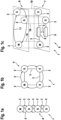
- Figure 1a shows a manufacturing plant 1.
- the manufacturing plant 1 comprises three process devices 2.
- the manufacturing plant 1 is, for example, part of a manufacturing and/or production facility, for example in a factory hall.
- a component can be manufactured and/or processed using the manufacturing plant, for example.
- the production facilities 2 are designed to carry out sub-steps.
- the production facilities 2 are designed, for example, as robots, stationary or mobile.
- the production facilities can also represent conveyor belts, processing stations such as drilling or sawing stations or welding systems.
- the production facilities 2 are arranged at a distance from one another and are connected to one another by means of connections 3, for example cable connections and/or radio connections, for data exchange.
- the production facilities 2 form a network in the form of a line.
- the process facilities 2 are each connected to one or two process facilities, with the connections being arranged in such a way that no branches occur.
- the connection of the process facilities 2 with the connections 3 form a physical network 4.
- Data can be exchanged within the physical network 4.
- the data exchange can be designed as data transfer or data acceptance.
- the data exchange is shown in the form of arrows 5.
- the process devices 2 are designed as real-time process devices.
- One process device 2 forms a master M, with the other process devices 2 forming slaves S.
- the master module M dominates and/or determines in particular the network communication.
- Figure 1b shows another production facility 1, where the production facility 1 again comprises four production facilities 2.
- the production facilities 2 are each connected to two neighboring production facilities 2.
- the network thus forms a ring network.
- one production facility 2 forms a master M, with the other production facilities 2 acting as slaves S.
- the network 4 is shown in its physical topology, whereby the physical topology can be described in particular by means of the arrows 5.
- Figure 1c shows schematically an embodiment of a production plant and/or a network 6, both in its physical topology 7 and in the virtual topology 8.
- the physical topology 7 describes the real arrangement of the process devices 2, the network switches 9 and their connections 3.
- the network 6 and the physical topology 7 comprise three process devices 2 and two network switches 9.
- a network switch 9 is connected to two process devices 2, one of these process devices 2 forming a master M and the other a slave S.
- the network switch 9 is connected to the other network switch with a connection, for example a cable. This can be used to exchange data.
- the other network switch 9 is additionally connected to a process device 2, this process device 2 forming a slave. Data can be exchanged between them using the connections 3 and the network switches 9, in particular between the process devices 2 and/or between the switches 9 or the Switches 9 and the process devices 2.
- the network switches 9 can be designed to retrieve data from the process devices 2 and/or to partially change data which is stored and/or saved there.
- the network switches 9 are designed to generate a virtual topology, in particular a software-defined virtual topology, which is designed as a real-time and/or as a time-sensitive network.
- the physical topology 7 is designed as a branched network and/or a branched topology, in particular star-shaped, with the process devices 2 each forming branches and/or rays of the star, for example, the virtual topology 8 is designed as a ring topology.
- the corresponding process devices 2 of the physical topology and virtual topology 8 are shown on top of each other using auxiliary projection lines 10.
- the data connections 11 are formed by means of the switches 9 and as a software solution. These connections 11 do not exist as real wired physical connections, but are designed as software-implemented connections. These connections 11 are designed in particular as time-sensitive network connections.
- the production plant 2 in its physical topology 7 can be converted into an abstract virtual topology 8 by means of the used and proposed process equipment 2 and the network switches 9, so that any virtual topologies 8 are available independently of the cabling 3.
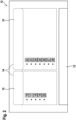
- FIG. 2 shows, by way of example, the structure of administration shell data in the administration shell 12 of a process device 2.
- the process device 2 comprises the physical asset 13, which is designed as a system component, for example, and additionally the administration shell 12.
- the administration shell data 14 is stored in the administration shell 12, which can also be designed as a storage unit and/or storage module, for example.
- the administration shell data 14 comprises TSN profile data 15.
- the TSN profile data 15 describes, for example, properties of the process device 2, for example its MAC address 16, its IP address 17, its ports 18, its cycle time 19 and its VLAN priority 20.
- the administration shell data 14 includes virtual topology data 21.
- the virtual topology data 21 are required, for example, to establish the virtual topology 8 and/or to operate it.
- the virtual topology data includes, for example, an activity parameter 22, an ID parameter 23, a topology type parameter 24, a topology ID parameter 25, an index parameter 26, a successor parameter 27 and a successor interface parameter 28.
- the virtual topology data 21 and/or its parameters can in particular be static, changeable and/or partially static and/or partially changeable. A change can be made, for example, by the network switches 9, for example when configuring the desired virtual topology 8.
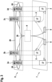
- FIG 3 shows, by way of example, the production plant 1 in its physical topology 7 and in its virtual topology 8.
- the production plant 1 comprises two network switches 9 in its physical topology, whereby the network switches 9 are designed as SDN controllers and are designed to configure, operate and/or change the virtual topology.
- the SDN controllers can also be designed as independent central components.
- the network switches 9 are connected to process devices 2 for data purposes, for example by means of cable lines or radio connections.
- the process devices 2 are designed to carry out a production sub-step.
- the process devices 2 have, as in Figure 2 shown, the asset 13 and the administration shell 14.
- a data connection between each other, in particular between the process devices 2, can be made possible by means of the switches 9, wherein the network switches 9 can also be designed to change the data and/or parameters in the administration shell data 14.
- the virtual topology 8 can be defined and/or operated by means of the virtual topology data 21.
- the virtual topology 8 is designed here as a ring network, wherein the virtual network connections 29 are generated by software using the real connections 3.
- the process devices 2 are referred to in the virtual topology as process devices 2a, 2b, 2c and 2d.
- the process device 2b forms a master M here. After the process device 2b forms a master M, it is assigned the index parameter 26 with the value zero. Furthermore, the process device 2b is assigned the value one as the successor parameter 27.
- the process device 2c forms a slave S and has the value one as index parameter 26 and the value two as successor parameter 27. Since process device 2b has the value one as successor parameter 27, it is specified in the virtual topology that this connection 29 must be made to process device 2c, since this has the index parameter 26 equal to one.
- the process device 2d is also designed as a slave S and has the value 2 as index parameter 26 and the value three as successor parameter 27, so that a connection must exist in the virtual topology between the process devices 2c and 2d.
- the process device 2a is also designed as a slave and has the value three as the index parameter 26 and the value zero as the follow-up parameter 27. Thus, there must be a connection between the process devices 2a and 2b in the virtual topology 8, since the process device 2b has the index parameter zero. Using these parameters, a time-sensitive network connection in the form of a virtual topology can be implemented in a production plant.
Landscapes
- Engineering & Computer Science (AREA)
- Computer Networks & Wireless Communication (AREA)
- Signal Processing (AREA)
- Health & Medical Sciences (AREA)
- Computing Systems (AREA)
- General Health & Medical Sciences (AREA)
- Medical Informatics (AREA)
- Small-Scale Networks (AREA)
Claims (10)
- Dispositif de processus (2) destiné à exécuter une étape partielle dans une installation de fabrication (1), comprenant un module réseau destiné à établir une connexion de réseautage chronosensiblecomprenant un module de mémoire, le module de mémoire comportant des données de coquille de gestion (14),les données de coquille de gestion (14) comprenant des données de topologie virtuelle (21) pour un réseautage défini par logiciel, les données de topologie virtuelle (21) étant configurées pour construire, exploiter, définir et/ou modifier le réseautage défini par logiciel, le réseautage défini par logiciel étant configuré pour définir et/ou construire une topologie virtuelle (8) d'un réseau, la topologie virtuelle (8) ne devant pas forcément correspondre à la structure et/ou à la topologie du réseau,caractérisé en ce que les données de topologie virtuelle comprennent un paramètre d'activité (22) destiné à décrire l'état de processus du dispositif de processus (2) .
- Dispositif de processus (2) selon la revendication 1, caractérisé en ce que les données de topologie virtuelle (21) comprennent un paramètre d'activité (22), un paramètre d'identification (23), un paramètre de type (24) de la topologie virtuelle, un paramètre d'identification de topologie (25), un paramètre d'indice (26) de la position dans la topologie virtuelle, un paramètre de successeur (27) et/ou un paramètre d'interface de successeur (28).
- Dispositif de processus (2) selon la revendication 1 ou 2, caractérisé en ce que les données de topologie virtuelle (21) forment et/ou comprennent des données adaptables et/ou modifiables.
- Dispositif de processus (2) selon l'une des revendications précédentes, caractérisé en ce que le module de réseau est configuré pour être couplé à un dispositif de processus (2) supplémentaire similaire, le couplage étant réalisé sous la forme d'une connexion de réseautage chronosensible, le module de réseau étant configuré pour effectuer une synchronisation temporelle, appliquer un ordonnancement de trafic et/ou appliquer une tolérance aux pannes.
- Dispositif de processus (2) selon l'une des revendications précédentes, caractérisé en ce que le module de réseau est configuré pour appliquer la norme IEEE 802.1 lors de la connexion au réseau.
- Dispositif de processus (2) selon l'une des revendications précédentes, caractérisé en ce que le dispositif de processus (2) forme un système d'axes, un robot ou un capteur.
- Réseau (6) comprenant au moins un commutateur de réseau (9) destiné à exploiter un réseau chronosensible, et comprenant au moins un dispositif de processus (2) selon l'une des revendications 1 à 6,le commutateur de réseau (9) pouvant être connecté à une pluralité de composants de réseau, les composants de réseau comportant au moins un dispositif de processus (2) selon l'une des revendications précédentes 1 à 6,le commutateur de réseau (9) possédant un module de mémoire avec des données de coquille de gestion de commutateur, les données de coquille de gestion de commutateur présentant des données de configuration destinées à configurer au moins une topologie virtuelle (8) sur la base du réseau chronosensible.
- Procédé d'exploitation et/ou de réglage d'une topologie virtuelle (8), comprenant au moins un dispositif de processus (2) selon l'une des revendications 1 à 6,
les données de topologie virtuelle (21) des dispositifs de processus (2) participants étant invoquées et/ou modifiées en vue de l'établissement et/ou la génération de la topologie virtuelle (8). - Programme informatique, le programme informatique étant configuré pour exécuter les étapes du procédé selon la revendication 8 lorsque le programme informatique est exécuté sur un ordinateur, un processeur, un commutateur de réseau (9) et/ou un dispositif de processus (2).
- Support de stockage lisible par machine, le support de stockage comprenant le programme informatique selon la revendication 9.
Applications Claiming Priority (1)
| Application Number | Priority Date | Filing Date | Title |
|---|---|---|---|
| DE102019205776.4A DE102019205776A1 (de) | 2019-04-23 | 2019-04-23 | Prozesseinrichtung, Netzwerkswitch, Netzwerk, Verfahren und Computerprogramm |
Publications (2)
| Publication Number | Publication Date |
|---|---|
| EP3731496A1 EP3731496A1 (fr) | 2020-10-28 |
| EP3731496B1 true EP3731496B1 (fr) | 2024-08-28 |
Family
ID=69784177
Family Applications (1)
| Application Number | Title | Priority Date | Filing Date |
|---|---|---|---|
| EP20161815.4A Active EP3731496B1 (fr) | 2019-04-23 | 2020-03-09 | Dispositif de traitement, réseau, procédé et programme informatique |
Country Status (2)
| Country | Link |
|---|---|
| EP (1) | EP3731496B1 (fr) |
| DE (1) | DE102019205776A1 (fr) |
Families Citing this family (1)
| Publication number | Priority date | Publication date | Assignee | Title |
|---|---|---|---|---|
| CN118890274B (zh) * | 2024-10-08 | 2024-12-13 | 之江实验室 | 一种时间敏感网络的混合式资源配置系统及方法 |
Family Cites Families (3)
| Publication number | Priority date | Publication date | Assignee | Title |
|---|---|---|---|---|
| DE102005061155A1 (de) | 2005-12-21 | 2007-06-28 | Bosch Rexroth Ag | Kommunikationsstruktur |
| EP3035606A1 (fr) * | 2014-12-15 | 2016-06-22 | Siemens Aktiengesellschaft | Procédé de transmission de données dans un réseau de communication comprenant au moins 2 réseaux locaux virtuels et appareil de communication pour un système d'automatisation industriel |
| US10122589B2 (en) * | 2016-04-08 | 2018-11-06 | Cisco Technology, Inc. | Configuring the design of an industrial automation network |
-
2019
- 2019-04-23 DE DE102019205776.4A patent/DE102019205776A1/de active Pending
-
2020
- 2020-03-09 EP EP20161815.4A patent/EP3731496B1/fr active Active
Also Published As
| Publication number | Publication date |
|---|---|
| EP3731496A1 (fr) | 2020-10-28 |
| DE102019205776A1 (de) | 2020-10-29 |
Similar Documents
| Publication | Publication Date | Title |
|---|---|---|
| EP2625822B1 (fr) | Procédé pour configurer un ou plusieurs appareils dans un réseau de communication basé sur ethernet | |
| EP3522482B1 (fr) | Procédé de communication de données dans un réseau industriel, procédé de commande, dispositif, programme informatique et support lisible par ordinateur | |
| EP1554839B1 (fr) | Procede et noeud pour utiliser en parallele un reseau de communication pour des applications temps reel et des applications non temps reel | |
| DE102020124313A1 (de) | Integration mehrerer kommunikationsbitübertragungsschichten und -protokolle in ein eingabe-/ausgabegerät der prozesssteuerung | |
| DE102019208678B4 (de) | Kommunikationsverfahren | |
| DE112017002494T5 (de) | Multiprotokoll-feldgerät in prozessleitsystemen | |
| EP2413538B1 (fr) | Prévention de boucles de transmission dans un réseau en anneau redondant | |
| EP3183851A1 (fr) | Noeud de distribution, réseau d'automatisation et procédé de transmission de paquets de données sensibles au temps réel et non sensibles au temps réel | |
| EP1657608A1 (fr) | Procédé et appareil pour actionner d'un réseau | |
| EP3679691A1 (fr) | Procédé de transmission de données et réseau de communication | |
| EP3625627A1 (fr) | Flux sommes pour des états réels et signaux de commande d'un système de commande distribué | |
| EP3731496B1 (fr) | Dispositif de traitement, réseau, procédé et programme informatique | |
| EP3616011B1 (fr) | Dispositif et procédé de surveillance d'un système d'automatisation | |
| EP3151475B1 (fr) | Procédé de communication de données asynchrone dans un réseau de donnees ethernet en temps réel | |
| DE102014112704B3 (de) | Netzwerksystem und Netzwerkteilnehmer zur Datenübertragung über eine Cloud-Infrastruktur und Verfahren zur Einrichtung | |
| EP2181527B1 (fr) | Noeud de commande pour un réseau constitué de noeuds de commande | |
| EP3654594A1 (fr) | Procédé de transmission de données, appareil de communication, programme informatique et support lisible par ordinateur | |
| EP2159959B1 (fr) | Procédé de détermination d'une topologie, composants de réseau et unité centrale | |
| EP4158852A1 (fr) | Appareil de terrain pour vérifier la qualité d'une connexion réseau | |
| EP4366276B1 (fr) | Système de communication modulaire et procédé de fonctionnement du système de communication | |
| EP4038865A1 (fr) | Procédé de transmission de données d'abonnement, composant de fourniture de données, composant de consommation de données, réseau et système | |
| DE102022120529B4 (de) | Verfahren und Einrichtung zum Betrieb einer Vielzahl von IO-Link-Geräten mittels eines IO-Link-Masters | |
| EP3716550A1 (fr) | Procédé de communication de données dans un réseau industriel, commande, réseau, programme informatique et support lisible par ordinateur | |
| WO2018215286A1 (fr) | Traitement distribué de données de processus | |
| EP3632051B1 (fr) | Initialisation d'abonnés de bus de données |
Legal Events
| Date | Code | Title | Description |
|---|---|---|---|
| PUAI | Public reference made under article 153(3) epc to a published international application that has entered the european phase |
Free format text: ORIGINAL CODE: 0009012 |
|
| STAA | Information on the status of an ep patent application or granted ep patent |
Free format text: STATUS: THE APPLICATION HAS BEEN PUBLISHED |
|
| AK | Designated contracting states |
Kind code of ref document: A1 Designated state(s): AL AT BE BG CH CY CZ DE DK EE ES FI FR GB GR HR HU IE IS IT LI LT LU LV MC MK MT NL NO PL PT RO RS SE SI SK SM TR |
|
| AX | Request for extension of the european patent |
Extension state: BA ME |
|
| STAA | Information on the status of an ep patent application or granted ep patent |
Free format text: STATUS: REQUEST FOR EXAMINATION WAS MADE |
|
| 17P | Request for examination filed |
Effective date: 20210428 |
|
| RBV | Designated contracting states (corrected) |
Designated state(s): AL AT BE BG CH CY CZ DE DK EE ES FI FR GB GR HR HU IE IS IT LI LT LU LV MC MK MT NL NO PL PT RO RS SE SI SK SM TR |
|
| STAA | Information on the status of an ep patent application or granted ep patent |
Free format text: STATUS: EXAMINATION IS IN PROGRESS |
|
| 17Q | First examination report despatched |
Effective date: 20220504 |
|
| REG | Reference to a national code |
Ref country code: DE Ref legal event code: R079 Free format text: PREVIOUS MAIN CLASS: H04L0029080000 Ipc: H04L0067120000 Ref document number: 502020008992 Country of ref document: DE |
|
| RIC1 | Information provided on ipc code assigned before grant |
Ipc: H04L 47/28 20220101ALN20240320BHEP Ipc: H04L 41/122 20220101ALI20240320BHEP Ipc: H04L 12/403 20060101ALI20240320BHEP Ipc: H04L 67/12 20220101AFI20240320BHEP |
|
| GRAP | Despatch of communication of intention to grant a patent |
Free format text: ORIGINAL CODE: EPIDOSNIGR1 |
|
| STAA | Information on the status of an ep patent application or granted ep patent |
Free format text: STATUS: GRANT OF PATENT IS INTENDED |
|
| INTG | Intention to grant announced |
Effective date: 20240430 |
|
| RIC1 | Information provided on ipc code assigned before grant |
Ipc: H04L 47/28 20220101ALN20240422BHEP Ipc: H04L 41/122 20220101ALI20240422BHEP Ipc: H04L 12/403 20060101ALI20240422BHEP Ipc: H04L 67/12 20220101AFI20240422BHEP |
|
| GRAS | Grant fee paid |
Free format text: ORIGINAL CODE: EPIDOSNIGR3 |
|
| GRAA | (expected) grant |
Free format text: ORIGINAL CODE: 0009210 |
|
| STAA | Information on the status of an ep patent application or granted ep patent |
Free format text: STATUS: THE PATENT HAS BEEN GRANTED |
|
| AK | Designated contracting states |
Kind code of ref document: B1 Designated state(s): AL AT BE BG CH CY CZ DE DK EE ES FI FR GB GR HR HU IE IS IT LI LT LU LV MC MK MT NL NO PL PT RO RS SE SI SK SM TR |
|
| REG | Reference to a national code |
Ref country code: CH Ref legal event code: EP |
|
| REG | Reference to a national code |
Ref country code: DE Ref legal event code: R096 Ref document number: 502020008992 Country of ref document: DE |
|
| REG | Reference to a national code |
Ref country code: IE Ref legal event code: FG4D Free format text: LANGUAGE OF EP DOCUMENT: GERMAN |
|
| REG | Reference to a national code |
Ref country code: LT Ref legal event code: MG9D |
|
| PG25 | Lapsed in a contracting state [announced via postgrant information from national office to epo] |
Ref country code: NO Free format text: LAPSE BECAUSE OF FAILURE TO SUBMIT A TRANSLATION OF THE DESCRIPTION OR TO PAY THE FEE WITHIN THE PRESCRIBED TIME-LIMIT Effective date: 20241128 |
|
| PG25 | Lapsed in a contracting state [announced via postgrant information from national office to epo] |
Ref country code: NL Free format text: LAPSE BECAUSE OF FAILURE TO SUBMIT A TRANSLATION OF THE DESCRIPTION OR TO PAY THE FEE WITHIN THE PRESCRIBED TIME-LIMIT Effective date: 20240828 Ref country code: FI Free format text: LAPSE BECAUSE OF FAILURE TO SUBMIT A TRANSLATION OF THE DESCRIPTION OR TO PAY THE FEE WITHIN THE PRESCRIBED TIME-LIMIT Effective date: 20240828 Ref country code: GR Free format text: LAPSE BECAUSE OF FAILURE TO SUBMIT A TRANSLATION OF THE DESCRIPTION OR TO PAY THE FEE WITHIN THE PRESCRIBED TIME-LIMIT Effective date: 20241129 Ref country code: PL Free format text: LAPSE BECAUSE OF FAILURE TO SUBMIT A TRANSLATION OF THE DESCRIPTION OR TO PAY THE FEE WITHIN THE PRESCRIBED TIME-LIMIT Effective date: 20240828 Ref country code: PT Free format text: LAPSE BECAUSE OF FAILURE TO SUBMIT A TRANSLATION OF THE DESCRIPTION OR TO PAY THE FEE WITHIN THE PRESCRIBED TIME-LIMIT Effective date: 20241230 |
|
| PG25 | Lapsed in a contracting state [announced via postgrant information from national office to epo] |
Ref country code: BG Free format text: LAPSE BECAUSE OF FAILURE TO SUBMIT A TRANSLATION OF THE DESCRIPTION OR TO PAY THE FEE WITHIN THE PRESCRIBED TIME-LIMIT Effective date: 20240828 |
|
| PG25 | Lapsed in a contracting state [announced via postgrant information from national office to epo] |
Ref country code: LV Free format text: LAPSE BECAUSE OF FAILURE TO SUBMIT A TRANSLATION OF THE DESCRIPTION OR TO PAY THE FEE WITHIN THE PRESCRIBED TIME-LIMIT Effective date: 20240828 |
|
| REG | Reference to a national code |
Ref country code: NL Ref legal event code: MP Effective date: 20240828 |
|
| PG25 | Lapsed in a contracting state [announced via postgrant information from national office to epo] |
Ref country code: IS Free format text: LAPSE BECAUSE OF FAILURE TO SUBMIT A TRANSLATION OF THE DESCRIPTION OR TO PAY THE FEE WITHIN THE PRESCRIBED TIME-LIMIT Effective date: 20241228 |
|
| PG25 | Lapsed in a contracting state [announced via postgrant information from national office to epo] |
Ref country code: HR Free format text: LAPSE BECAUSE OF FAILURE TO SUBMIT A TRANSLATION OF THE DESCRIPTION OR TO PAY THE FEE WITHIN THE PRESCRIBED TIME-LIMIT Effective date: 20240828 |
|
| PG25 | Lapsed in a contracting state [announced via postgrant information from national office to epo] |
Ref country code: RS Free format text: LAPSE BECAUSE OF FAILURE TO SUBMIT A TRANSLATION OF THE DESCRIPTION OR TO PAY THE FEE WITHIN THE PRESCRIBED TIME-LIMIT Effective date: 20241128 Ref country code: ES Free format text: LAPSE BECAUSE OF FAILURE TO SUBMIT A TRANSLATION OF THE DESCRIPTION OR TO PAY THE FEE WITHIN THE PRESCRIBED TIME-LIMIT Effective date: 20240828 |
|
| PG25 | Lapsed in a contracting state [announced via postgrant information from national office to epo] |
Ref country code: RS Free format text: LAPSE BECAUSE OF FAILURE TO SUBMIT A TRANSLATION OF THE DESCRIPTION OR TO PAY THE FEE WITHIN THE PRESCRIBED TIME-LIMIT Effective date: 20241128 Ref country code: PT Free format text: LAPSE BECAUSE OF FAILURE TO SUBMIT A TRANSLATION OF THE DESCRIPTION OR TO PAY THE FEE WITHIN THE PRESCRIBED TIME-LIMIT Effective date: 20241230 Ref country code: PL Free format text: LAPSE BECAUSE OF FAILURE TO SUBMIT A TRANSLATION OF THE DESCRIPTION OR TO PAY THE FEE WITHIN THE PRESCRIBED TIME-LIMIT Effective date: 20240828 Ref country code: NO Free format text: LAPSE BECAUSE OF FAILURE TO SUBMIT A TRANSLATION OF THE DESCRIPTION OR TO PAY THE FEE WITHIN THE PRESCRIBED TIME-LIMIT Effective date: 20241128 Ref country code: NL Free format text: LAPSE BECAUSE OF FAILURE TO SUBMIT A TRANSLATION OF THE DESCRIPTION OR TO PAY THE FEE WITHIN THE PRESCRIBED TIME-LIMIT Effective date: 20240828 Ref country code: LV Free format text: LAPSE BECAUSE OF FAILURE TO SUBMIT A TRANSLATION OF THE DESCRIPTION OR TO PAY THE FEE WITHIN THE PRESCRIBED TIME-LIMIT Effective date: 20240828 Ref country code: IS Free format text: LAPSE BECAUSE OF FAILURE TO SUBMIT A TRANSLATION OF THE DESCRIPTION OR TO PAY THE FEE WITHIN THE PRESCRIBED TIME-LIMIT Effective date: 20241228 Ref country code: HR Free format text: LAPSE BECAUSE OF FAILURE TO SUBMIT A TRANSLATION OF THE DESCRIPTION OR TO PAY THE FEE WITHIN THE PRESCRIBED TIME-LIMIT Effective date: 20240828 Ref country code: GR Free format text: LAPSE BECAUSE OF FAILURE TO SUBMIT A TRANSLATION OF THE DESCRIPTION OR TO PAY THE FEE WITHIN THE PRESCRIBED TIME-LIMIT Effective date: 20241129 Ref country code: FI Free format text: LAPSE BECAUSE OF FAILURE TO SUBMIT A TRANSLATION OF THE DESCRIPTION OR TO PAY THE FEE WITHIN THE PRESCRIBED TIME-LIMIT Effective date: 20240828 Ref country code: ES Free format text: LAPSE BECAUSE OF FAILURE TO SUBMIT A TRANSLATION OF THE DESCRIPTION OR TO PAY THE FEE WITHIN THE PRESCRIBED TIME-LIMIT Effective date: 20240828 Ref country code: BG Free format text: LAPSE BECAUSE OF FAILURE TO SUBMIT A TRANSLATION OF THE DESCRIPTION OR TO PAY THE FEE WITHIN THE PRESCRIBED TIME-LIMIT Effective date: 20240828 |
|
| PG25 | Lapsed in a contracting state [announced via postgrant information from national office to epo] |
Ref country code: SM Free format text: LAPSE BECAUSE OF FAILURE TO SUBMIT A TRANSLATION OF THE DESCRIPTION OR TO PAY THE FEE WITHIN THE PRESCRIBED TIME-LIMIT Effective date: 20240828 Ref country code: DK Free format text: LAPSE BECAUSE OF FAILURE TO SUBMIT A TRANSLATION OF THE DESCRIPTION OR TO PAY THE FEE WITHIN THE PRESCRIBED TIME-LIMIT Effective date: 20240828 Ref country code: RO Free format text: LAPSE BECAUSE OF FAILURE TO SUBMIT A TRANSLATION OF THE DESCRIPTION OR TO PAY THE FEE WITHIN THE PRESCRIBED TIME-LIMIT Effective date: 20240828 |
|
| PG25 | Lapsed in a contracting state [announced via postgrant information from national office to epo] |
Ref country code: EE Free format text: LAPSE BECAUSE OF FAILURE TO SUBMIT A TRANSLATION OF THE DESCRIPTION OR TO PAY THE FEE WITHIN THE PRESCRIBED TIME-LIMIT Effective date: 20240828 |
|
| PG25 | Lapsed in a contracting state [announced via postgrant information from national office to epo] |
Ref country code: CZ Free format text: LAPSE BECAUSE OF FAILURE TO SUBMIT A TRANSLATION OF THE DESCRIPTION OR TO PAY THE FEE WITHIN THE PRESCRIBED TIME-LIMIT Effective date: 20240828 |
|
| PG25 | Lapsed in a contracting state [announced via postgrant information from national office to epo] |
Ref country code: IT Free format text: LAPSE BECAUSE OF FAILURE TO SUBMIT A TRANSLATION OF THE DESCRIPTION OR TO PAY THE FEE WITHIN THE PRESCRIBED TIME-LIMIT Effective date: 20240828 Ref country code: SK Free format text: LAPSE BECAUSE OF FAILURE TO SUBMIT A TRANSLATION OF THE DESCRIPTION OR TO PAY THE FEE WITHIN THE PRESCRIBED TIME-LIMIT Effective date: 20240828 |
|
| REG | Reference to a national code |
Ref country code: DE Ref legal event code: R097 Ref document number: 502020008992 Country of ref document: DE |
|
| PLBE | No opposition filed within time limit |
Free format text: ORIGINAL CODE: 0009261 |
|
| STAA | Information on the status of an ep patent application or granted ep patent |
Free format text: STATUS: NO OPPOSITION FILED WITHIN TIME LIMIT |
|
| PGFP | Annual fee paid to national office [announced via postgrant information from national office to epo] |
Ref country code: DE Payment date: 20250522 Year of fee payment: 6 |
|
| 26N | No opposition filed |
Effective date: 20250530 |
|
| PG25 | Lapsed in a contracting state [announced via postgrant information from national office to epo] |
Ref country code: SE Free format text: LAPSE BECAUSE OF FAILURE TO SUBMIT A TRANSLATION OF THE DESCRIPTION OR TO PAY THE FEE WITHIN THE PRESCRIBED TIME-LIMIT Effective date: 20240828 |
|
| PG25 | Lapsed in a contracting state [announced via postgrant information from national office to epo] |
Ref country code: MC Free format text: LAPSE BECAUSE OF FAILURE TO SUBMIT A TRANSLATION OF THE DESCRIPTION OR TO PAY THE FEE WITHIN THE PRESCRIBED TIME-LIMIT Effective date: 20240828 |
|
| REG | Reference to a national code |
Ref country code: CH Ref legal event code: H13 Free format text: ST27 STATUS EVENT CODE: U-0-0-H10-H13 (AS PROVIDED BY THE NATIONAL OFFICE) Effective date: 20251023 |
|
| PG25 | Lapsed in a contracting state [announced via postgrant information from national office to epo] |
Ref country code: LU Free format text: LAPSE BECAUSE OF NON-PAYMENT OF DUE FEES Effective date: 20250309 |
|
| GBPC | Gb: european patent ceased through non-payment of renewal fee |
Effective date: 20250309 |
|
| REG | Reference to a national code |
Ref country code: BE Ref legal event code: MM Effective date: 20250331 |
|
| PG25 | Lapsed in a contracting state [announced via postgrant information from national office to epo] |
Ref country code: GB Free format text: LAPSE BECAUSE OF NON-PAYMENT OF DUE FEES Effective date: 20250309 |
|
| PG25 | Lapsed in a contracting state [announced via postgrant information from national office to epo] |
Ref country code: FR Free format text: LAPSE BECAUSE OF NON-PAYMENT OF DUE FEES Effective date: 20250331 |
|
| PG25 | Lapsed in a contracting state [announced via postgrant information from national office to epo] |
Ref country code: BE Free format text: LAPSE BECAUSE OF NON-PAYMENT OF DUE FEES Effective date: 20250331 |
|
| PG25 | Lapsed in a contracting state [announced via postgrant information from national office to epo] |
Ref country code: CH Free format text: LAPSE BECAUSE OF NON-PAYMENT OF DUE FEES Effective date: 20250331 |
|
| PG25 | Lapsed in a contracting state [announced via postgrant information from national office to epo] |
Ref country code: IE Free format text: LAPSE BECAUSE OF NON-PAYMENT OF DUE FEES Effective date: 20250309 |