EP3632051B1 - Initialisation d'abonnés de bus de données - Google Patents
Initialisation d'abonnés de bus de données Download PDFInfo
- Publication number
- EP3632051B1 EP3632051B1 EP18726426.2A EP18726426A EP3632051B1 EP 3632051 B1 EP3632051 B1 EP 3632051B1 EP 18726426 A EP18726426 A EP 18726426A EP 3632051 B1 EP3632051 B1 EP 3632051B1
- Authority
- EP
- European Patent Office
- Prior art keywords
- data
- bus
- data bus
- data packet
- instruction list
- Prior art date
- Legal status (The legal status is an assumption and is not a legal conclusion. Google has not performed a legal analysis and makes no representation as to the accuracy of the status listed.)
- Active
Links
Images


Classifications
-
- H—ELECTRICITY
- H04—ELECTRIC COMMUNICATION TECHNIQUE
- H04L—TRANSMISSION OF DIGITAL INFORMATION, e.g. TELEGRAPHIC COMMUNICATION
- H04L12/00—Data switching networks
- H04L12/28—Data switching networks characterised by path configuration, e.g. LAN [Local Area Networks] or WAN [Wide Area Networks]
- H04L12/40—Bus networks
- H04L12/40169—Flexible bus arrangements
-
- G—PHYSICS
- G06—COMPUTING OR CALCULATING; COUNTING
- G06F—ELECTRIC DIGITAL DATA PROCESSING
- G06F13/00—Interconnection of, or transfer of information or other signals between, memories, input/output devices or central processing units
- G06F13/14—Handling requests for interconnection or transfer
- G06F13/36—Handling requests for interconnection or transfer for access to common bus or bus system
- G06F13/362—Handling requests for interconnection or transfer for access to common bus or bus system with centralised access control
-
- G—PHYSICS
- G06—COMPUTING OR CALCULATING; COUNTING
- G06F—ELECTRIC DIGITAL DATA PROCESSING
- G06F9/00—Arrangements for program control, e.g. control units
- G06F9/06—Arrangements for program control, e.g. control units using stored programs, i.e. using an internal store of processing equipment to receive or retain programs
- G06F9/46—Multiprogramming arrangements
- G06F9/54—Interprogram communication
- G06F9/546—Message passing systems or structures, e.g. queues
-
- H—ELECTRICITY
- H04—ELECTRIC COMMUNICATION TECHNIQUE
- H04L—TRANSMISSION OF DIGITAL INFORMATION, e.g. TELEGRAPHIC COMMUNICATION
- H04L12/00—Data switching networks
- H04L12/28—Data switching networks characterised by path configuration, e.g. LAN [Local Area Networks] or WAN [Wide Area Networks]
- H04L12/42—Loop networks
- H04L12/423—Loop networks with centralised control, e.g. polling
-
- H—ELECTRICITY
- H04—ELECTRIC COMMUNICATION TECHNIQUE
- H04L—TRANSMISSION OF DIGITAL INFORMATION, e.g. TELEGRAPHIC COMMUNICATION
- H04L41/00—Arrangements for maintenance, administration or management of data switching networks, e.g. of packet switching networks
- H04L41/08—Configuration management of networks or network elements
- H04L41/0803—Configuration setting
-
- H—ELECTRICITY
- H04—ELECTRIC COMMUNICATION TECHNIQUE
- H04L—TRANSMISSION OF DIGITAL INFORMATION, e.g. TELEGRAPHIC COMMUNICATION
- H04L69/00—Network arrangements, protocols or services independent of the application payload and not provided for in the other groups of this subclass
- H04L69/22—Parsing or analysis of headers
-
- H—ELECTRICITY
- H04—ELECTRIC COMMUNICATION TECHNIQUE
- H04L—TRANSMISSION OF DIGITAL INFORMATION, e.g. TELEGRAPHIC COMMUNICATION
- H04L12/00—Data switching networks
- H04L12/28—Data switching networks characterised by path configuration, e.g. LAN [Local Area Networks] or WAN [Wide Area Networks]
- H04L12/40—Bus networks
- H04L2012/4026—Bus for use in automation systems
Definitions
- the invention relates generally to the initialization of data bus participants and, in particular, to the programming of data bus participants of a ring bus using instruction lists.
- Data bus devices are typically found in automation systems.
- a data bus device is used to control or monitor a process within an automation system. This is accomplished by outputting control signals, e.g., to actuators, and/or by receiving measurement signals, e.g., from sensors in the automation system.
- Automation systems are primarily used to control industrial plants, buildings, and means of transport. Controlling an automation system usually requires several sensors and actuators. These monitor and control the process performed by the system. The various sensors and actuators in an automation system are often referred to as automation devices.
- These automation devices can either be connected directly to a controller of the automation system or can first be connected to input and output modules, often referred to as I/O modules. These can then be connected directly to the controller.
- the automation devices can either be integrated directly into the I/O modules or can be connected to them via cable or wirelessly.
- the control of an automation system is usually accomplished with the help of one or more programmable logic controllers (PLCs).
- PLCs programmable logic controllers
- the PLCs can be arranged hierarchically or decentrally within an automation system. There are different performance classes of PLCs, so that they can perform different controls and regulations depending on their computing and storage capacity.
- a PLC has inputs, outputs, an operating system (firmware) and an interface via which a user program can be loaded.
- the user program specifies how the outputs are to be switched depending on the inputs.
- the inputs and outputs can be connected to the automation devices and/or the I/O modules and, based on the logic stored in the user program, the process carried out by the automation system can be monitored or controlled.
- the process is monitored by the sensors and controlled by the actuators.
- the controller can also be referred to as a central controller or central processing unit and assumes control for at least one automation device or I/O module connected to the controller.
- bus systems are now mostly used in automation technology to connect the automation devices or I/O modules to the controller.
- the participants in a bus system are also referred to as bus participants. Because data is exchanged on the bus system, the bus participants are also often referred to as data bus participants.
- individual groups of automation devices or I/O modules are often first connected to each other to form a local bus system using a specialised local bus. Subsequently, at least one participant in this local bus is connected to the bus system that is connected to the controller.
- the local bus system may differ from the bus system used to establish the connection with the controller.
- the participant in a group of local bus participants that is connected to the controller's bus system is often referred to as the local bus master.
- the term head station of the local bus system is also used.
- This local bus master can contain additional logic, circuits or functionalities than other local bus participants that are necessary for connecting to the controller's bus system.
- the local bus master itself can also contain a PLC. This participant can also have logic and circuits for converting between the two bus systems.
- the local bus master can therefore also be designed as a gateway or bus converter and ensures that data in the format of one bus system is converted into the format of the local bus system and vice versa. In most cases, but not necessarily, the local bus master is specialized in connecting the local bus to the higher-level bus.
- the local buses used are usually tailored to the specific application requirements of the automation devices or I/O modules or take their specific hardware design into account.
- the groups of automation devices or I/O modules of the local bus system usually form a subgroup of the automation system for performing a specific task in the process executed by the automation system.
- the data exchanged on the buses for the process is also often referred to as local bus data or process data because this data contains information for regulating or controlling the process executed by the automation system.
- This data can include, among other things, measurement data, control data, status data and/or other information.
- other data can be prefixed ( header ) or appended ( tail) to this data.
- This other data can contain information about the data or information about internal communication on the local bus. A variety of different information is known here, which can be prefixed or appended to the data depending on the bus protocol used.
- a local bus is a ring bus, which is a specialized form of local bus, such as US 5,472,347 A known.
- the data bus devices for example the automation devices or I/O modules, are each connected to their directly adjacent data bus devices and data is forwarded sequentially from one data bus device to the next. The data is therefore not sent to all data bus devices at the same time, but sequentially, with each data bus device receiving data from its upstream data bus device and forwarding it to its downstream data bus device. Between receiving the data and forwarding it, the data bus device can process the received data. When the data has reached the last data bus device in the series, the data is passed back sequentially from the last data bus device to the first data bus device. The data can be passed back either through all data bus devices or bypassed using a bypass line.
- the ring bus therefore has a downstream and upstream data flow.
- the data in a ring bus is usually transmitted in the form of data packets that pass through all data bus devices.
- programming the data bus devices is complex.
- programming the data bus devices requires interrupting the bus transmission or programming the data bus device via an external interface, during which time the data bus device cannot participate in communication on the local bus.
- the at least one instruction list can be stored in the data bus participant itself, for example, in a memory of the data bus participant, or in a memory connected to the data bus participant.
- the connection between the data bus participant and the memory can be wired or wireless.
- the memory is an additional module that is connected to the Data bus devices can be connected.
- the memory can be configured as desired.
- the first data packet can also be referred to as a communication data packet and preferably does not contain any process data.
- a communication data packet contains data, in particular for programming and/or controlling and/or monitoring and/or identifying at least one data bus participant.
- the communication data packet has an address assigned to at least one data bus participant.
- the data bus participant is configured to evaluate the address and read the communication data packet, so that the data bus participant can be programmed with the information contained in the communication data packet, for example the instruction list, or stores this information and is thus programmed.
- the method according to the invention further comprises receiving a second data packet via the local bus, wherein the second data packet contains process data. This received process data can then be processed by executing instructions from the at least one instruction list received in the first data packet.
- the second data packet can also be referred to as a process data packet and contains process data that is sent and/or received by the data bus participants of the local bus.
- the process data packet does not have an address for transmitting the process data to or from a data bus participant in the local bus.
- the process data is arranged, for example, in such a way that data bus participants can recognize the process data belonging to the respective data bus participant based on the respective position of the process data in the process data packet, for example one or more bits within an assigned contiguous data block (1 byte).
- the process data packet has an identifier (IDE) that is assigned to the type of data packet, i.e. the process data packet, and is identifiable by the data bus participant.
- IDE identifier
- the process data can also be referred to as local bus data.
- the node By using an initial data packet, which is sent to a data bus node in a local bus-compliant communication, the node can be programmed without the need for external programming. Programming for the data bus node therefore takes place while the local bus is running. Once the data bus node has saved the instruction list contained in the first data packet, programming of the data bus node is complete, and the node can process the process data contained in a subsequent local bus-compliant communication.
- this further comprises comparing the address received in the first data packet with an address of the data bus participant. Only if the addresses match does the data bus participant save the instruction list following in the first data packet, so that only the data bus participant to which the instruction list is addressed is programmed.
- the address can also be a group address, i.e. several data bus participants will detect a match with the address, so that several data bus participants can be programmed. This is advantageous, for example, if several data bus participants perform the same task in the automation system and are accordingly equipped with the same sensors and/or actuators but, for example, occupy different positions in the automation process.
- the first and second data packets are received in a local bus-compliant cycle frame.
- the first and second data packets can be received in different cycle frames.
- a cycle frame can be defined, for example, as a recurring (cyclic), preferably equidistant, time interval in which data can be transmitted on the local bus.
- the cycle frame has, for example, at least one start identifier (SOC) and a time range for the transmission of data.
- SOC start identifier
- Several start identifiers (SOC) of successive cycle frames are advantageously arranged at a temporally equidistant interval. to each other.
- the start identifier (SOC) and the data packets are transmitted via the local bus and pass through all data bus participants.
- the start identifier (SOC) is transmitted separately, i.e., as a standalone symbol, or advantageously, it is included in a start data packet (SOC packet).
- the cycle frame also has a trailer.
- the trailer has a variable length and follows the time range for data transmission, preferably up to the following start identifier (SOC) of the next cycle frame.
- SOC start identifier
- the trailer has idle data.
- the cycle frame is generated by a local bus master.
- This local bus master can already specify the programming based on the process data to be processed. This has the advantage that there is no interruption in communication. Furthermore , the additional overhead for the local bus master is very low because it does not have to use a separate communication channel for programming or laboriously adapt the local bus-compliant communication. Instead, the local bus master can integrate the programming into the normal process data communication.
- the second data packet further comprises an instruction list index (ILI).
- This instruction list index is used to select an instruction list for processing the received process data.
- the instruction list index informs the data bus participant about which stored instruction list is to be used.
- An instruction list index is thus assigned to an instruction list or vice versa, so that the instruction list to be used can be identified with the aid of the instruction list index.
- the instruction list index preferably has a value that is assigned to an instruction list, for example, the value points to a specific instruction list or to its memory location.
- the value itself can be the memory address where the instruction list is stored in the data bus participant or where at least a first instruction of the instruction list is stored.
- the value can also point to a memory area in which the corresponding instruction list is stored.
- the value of the instruction list index can, for example, also be used as input to a lookup table ( LUT).
- the value of the instruction list index is the input value of the conversion table.
- the output value of the conversion table can be the memory address of the first instruction in the associated instruction list or otherwise identify the instruction list.
- the instruction list index can preferably have a value from a fixed value range.
- the instruction list index can come from the bit value range between 0000 and 1111. However, it is clear to those skilled in the art that other value ranges can also be used.
- the conversion table can be stored in software or hardware, for example in the form of logic, and can specify a unique conversion from an input value to an output value, with the output value providing an indication of the instruction list to be used. How a connection is established between the instruction list index and the instruction list depends on the conversion table.
- the use of a conversion table can also be referred to as indirect assignment. With both direct and indirect assignments, the instruction list to be used by the data bus participant can be uniquely identified, i.e. found, via the instruction list index. The instruction list found via the instruction list index is then executed by the data bus participant to process the process data in the second data packet. The set of instructions from the selected instruction list is processed. If the instruction list index contains a reference to an instruction list that is not present on the data bus node, the data bus node can report an error. The data bus node can also ignore the instruction list index and not process any instruction list for the process data.
- the first and second data packets have a number of symbols, each symbol having a number of bits, for example 8 bits, i.e. 1 byte.
- the data packets pass through the local bus in the form of these symbols, i.e. unit by unit, piece by piece, or part by part. Such a part of the data packets is also referred to below as a piece or unit. This means that the data bus users only have a part of the data packets available at any given time. A data bus user receives the first and second data packets symbol by symbol.
- the data bus user forwards the part just processed to the downstream data bus user and, in the same step, receives a new part of the data packets from the upstream data bus user.
- Processing a part of a data packet can also consist in the data bus user skipping that part of the data packet. For example, all data bus nodes to which the first data packet is not addressed can skip the at least one instruction list contained in this data packet, and only the data bus node to which the first data packet is addressed can store the instruction list. In order to ensure a deterministic processing time, each part of the data packet always remains at a data bus node for the same length of time, regardless of whether processing is taking place.
- Processing the parts of the first data packet can either consist of skipping, i.e. not processing, the at least one instruction list, or in storing it if the first data packet is addressed to the data bus node that receives the respective parts.
- Processing the parts of the second data packet can consist of performing a bit operation on the received process data. In this case, the processing can also be said to be bit-granular.
- bit operations that can be performed are based, for example, on a reduced instruction set that the data bus participant can execute, such as "SKIP", “MOVE”, “NEGATION”, “INCREMENT”, “AND”, and “OR”, or a combination thereof.
- Which bit operations are to be executed is stored in the data bus node using instruction lists.
- An instruction list can be sent to the respective data bus node in a first data packet and represents the programming of the data bus node.
- These instruction lists contain at least one instruction for each part of the second data packet or for each bit of the second data packet, i.e., an operation to be performed with the corresponding bit. For each symbol, a fixed number or a predetermined number of instructions can be present in the instruction list.
- each data bus node executes a certain number of instructions per symbol in the time available for processing.
- the corresponding instruction list for the corresponding bit can be empty or contain a "SKIP" instruction.
- the instruction list can also specify the number of repetitions for a specific instruction.
- the instruction list can contain a "SKIP” instruction with the instruction to repeat it twice. In this case, the next two bits are skipped rather than processed. Parameters can also be specified for the "MOVE,”"NEGATION,””INCREMENT,””AND,” and "OR” instructions.
- the address in the first data packet is a unique address of the data bus participant to which the first data packet is directed.
- directed means that the instruction list contained in the first data packet is only stored by the data bus participant whose address matches the unique address in the first data packet. This means that programming is only carried out on the data bus participant whose address matches the address in the first data packet.
- the first data packet can accordingly also be referred to as a directed or specific data packet because it is intended for only one data bus participant or a specific group of data bus participants, whereas the second data packet does not contain an address and can accordingly be referred to as an undirected or indeterminate data packet.
- the second data packet is indeterminate because it carries the process data for all data bus participants of the local bus. It can also be said that the first data packet represents asynchronous communication, whereas the second data packet represents synchronous communication.
- the communication of the first data packet is asynchronous because the first data packet does not have to be resent in each cycle frame, but is only used once to program a data bus participant.
- the communication of the second data packet is synchronous because the second data packet is repeated cyclically.
- the process data does not always have to assume the same value, but it is clear to the expert that in automation the same process steps are repeated over and over again, which makes the presence of cyclically recurring process data necessary.
- a data bus subscriber of a local bus in particular a ring bus
- the data bus subscriber has a means for receiving a first data packet via the local bus, wherein the first data packet has an address of the data bus subscriber to which it is directed and at least one instruction list with a set of instructions for processing process data.
- the data bus subscriber according to the invention further has a means for receiving a second data packet via the local bus, wherein the second data packet contains process data.
- the means for receiving can be a receiver circuit or a transceiver circuit.
- the circuits are implemented, for example, in an application-specific integrated circuit ( ASIC) or in a field-programmable (logic) gate array ( FPGA).
- the data bus participant further comprises a means for executing instructions of the at least one instruction list for processing the received process data.
- the means for executing can be a microcontroller or a computing circuit, which can be formed, in particular, from gate elements of an integrated circuit.
- the computing circuit can be embodied as digital logic, which is, in particular, formed at least as part of a semiconductor chip.
- the circuits can be implemented in an ASIC or an FPGA.
- the latter further comprises a means for transmitting the received second data packet to another data bus node via the local bus.
- the data bus node can send the second data packet symbolically to another data bus node via the local bus.
- the other data bus node can be a data bus node that directly follows the sending data bus node.
- the transmission of data can be synchronized for all data bus nodes, for example, to a timing specified by the local bus master, or can be triggered by the receipt of further data packets.
- a method for operating a local bus master of a local bus comprising generating at least one instruction list with a set of instructions for processing process data for a data bus subscriber, generating a first data packet, the first data packet comprising an address of the data bus subscriber to which the first data packet is directed, and the at least one instruction list, generating a second data packet, the second data packet comprising process data, and sending the first and second data packets to the data bus subscriber via the local bus.
- the first and second data packets each have a number of symbols, each symbol having a number of bits, and the data packets are sent symbol by symbol to the data bus participant.
- the local bus master sends a first and second data packet at regular intervals, and these successively pass through all data bus participants in the downward direction, i.e., away from the local bus master.
- the last data bus participant in the local bus then sends the parts one after the other back to the local bus master in the upward direction, i.e., toward the local bus master.
- the returned parts either pass through all data bus participants again or are routed past them to the local bus master.
- the above-mentioned object is also achieved by a local bus master of a local bus, in particular a ring bus, with a data bus participant.
- the local bus master has a means for generating at least one instruction list with a set of instructions for processing process data for the data bus participant, as well as a means for generating a first data packet. wherein the first data packet comprises an address of the data bus subscriber to which the first data packet is directed, and the at least one instruction list.
- the local bus master according to the invention comprises a means for generating a second data packet, wherein the second data packet comprises process data.
- the means for generating can be a processor, a microcontroller, or a computing circuit, which can in particular be formed from gate elements of an integrated circuit.
- the computing circuit can be designed as digital logic, which is in particular designed as at least part of a semiconductor chip.
- the circuits can be implemented in an ASIC or an FPGA.
- the local bus master has a means for transmitting the first and second data packets to the data bus subscriber via the local bus.
- the two data packets can be transmitted in one cycle frame, which the transmitting means can generate.
- the transmitting means can also transmit the two data packets in different cycle frames and generate the corresponding cycle frames.
- the transmitting means can be a transmitter circuit or a transceiver circuit.
- the circuits are implemented, for example, in an ASIC or FPGA.
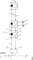
- FIG. 1 shows a schematic block diagram of an automation system. It will be understood by those skilled in the art that the automation system shown is only an example, and that all elements, modules, components, participants, and units belonging to the automation system may be configured differently but may nevertheless fulfill the basic functionalities described here.
- the automation system shown has a higher-level controller 1, which can be implemented, for example, with a programmable logic controller (PLC).
- PLC programmable logic controller
- Such a PLC 1 is basically used to control and regulate the process carried out by the automation system.
- PLCs 1 in automation systems also perform more advanced functions, such as visualization, alarm generation, and recording of all process-related data, and as such, the PLC 1 functions as a human-machine interface.
- PLC 1s are available in different performance classes, each with different resources (computing capacity, memory capacity, number and type of inputs and outputs, and interfaces) that enable the PLC 1 to control and regulate the process of the automation system.
- a PLC 1 usually has a modular design and consists of individual components, each of which performs a different task.
- a PLC 1 consists of a central processing unit (with one or more main processors and memory modules) and several modules with inputs and outputs. Such modular PLC 1s can be easily expanded by adding modules. This depends on the complexity of the process and the The complexity of the automation system's design determines which modules must be integrated into the PLC 1. In today's automation systems, the PLC 1 is usually no longer an independent system; instead, the PLC 1 is connected to the Internet or Intranet via appropriate interfaces (not shown here). This means that the PLC 1 is part of a network via or from which the PLC 1 can receive information, instructions, programming, etc.
- the PLC 1 can obtain information about the materials fed into the process via a connection to a computer on the Intranet or Internet, so that the process can be optimally controlled, for example by knowing their quantity or quality. It is also conceivable for the PLC 1 to be controlled by a user via the Intranet or Internet. For example, a user can access the PLC 1 with the help of a computer, also known as a host computer, and check, change, or correct its user programming. Accordingly, access to PLC 1 is possible from one or more remote control stations or control centers.
- the control computers may, if necessary, have visualization devices for displaying process sequences.
- the PLC 1 is connected to automation devices. To keep the wiring effort to a minimum, bus systems are used for these connections.
- Figure 1 In the embodiment shown, the PLC 1 is connected to a local bus master 3 of a subordinate local bus system via a higher-level bus 2, which in the embodiment shown here can be a fieldbus.
- a local bus master 3 of a local bus can be connected to the higher-level bus 2, as in the embodiment shown here, but also any other devices—not shown here—that are designed to communicate with the PLC 1.
- the higher-level bus 2 is connected to the local bus master 3.
- the local bus master 3 has a first interface 4, which is designed such that it can be connected to the higher-level bus 2.
- the interface 4 can, for example, have a receptacle in the form of a socket, and the higher-level bus 2 can have a plug which can be received by the socket.
- the plug and the socket can be, for example, a modular plug and a modular socket, i.e. each wire of the higher-level bus 2 is electrically or optically connected to a connection in the modular socket.
- an interface 4 can be designed so that the local bus master 3 can be electrically or optically connected to the higher-level bus 2.
- Those skilled in the art will be aware of screw, twist, click or plug connections with the aid of which an electrical or optical connection can be established. In this case, a male plug is usually received by a female counterpart. This receptacle not only establishes the electrical or optical connection but also ensures that the two parts are mechanically coupled and can only be separated from one another again with the application of a certain force.
- the higher-level bus 2 it is also conceivable for the higher-level bus 2 to be permanently wired to the interface 4.
- the local bus master 3 in the embodiment shown here has a further second interface for connecting the local bus master 3 to the local bus.
- Data bus nodes 7a, 7b, ..., 7n are connected to the local bus or form the local bus.
- the local bus is advantageously designed such that a data packet sent by the local bus master 3 is transmitted through all data bus nodes 7a, 7b, ..., 7n connected to the local bus and back to the local bus master 3.
- a data bus node 7a, 7b, ..., 7n always receives only a portion of the data packet from its upstream data bus node 7a, 7b, ..., 7n.
- the local bus is advantageously designed in a ring-shaped structure. Such local buses can also be referred to as a ring bus 6.
- the local bus can alternatively be designed in a strand-shaped or star-shaped structure, or in a combination or hybrid form of the aforementioned.
- the sending and receiving of the data packets is accomplished via the second interface of the local bus master 3.
- the second interface is divided into a first part 5a and a second part 5b.
- the first part 5a of the second interface establishes the downlink in the ring bus 6, and the second part 5b of the second interface establishes the uplink in the ring bus 6.
- the ring bus 6, whose data transmission direction is indicated by arrows in the Figure 1 shown embodiment, has a plurality of data bus participants 7a, 7b, ..., 7n in the embodiment shown here.
- These data bus participants 7a, 7b, ..., 7n each have an interface 8 in the embodiment shown here in order to receive data from an upstream or preceding data bus participant 7a, 7b, ..., 7n.
- data bus participant 7a it receives data from the upstream local bus master 3 via the interface 8.
- the data bus participants 7a, 7b, ..., 7n in the embodiment shown here each have an interface 9 in order to forward data to a downstream or subsequent data bus participant 7a, 7b, ..., 7n.
- interfaces 8 and 9 are used to propagate data in the downstream direction of the ring bus 6, i.e. away from the local bus master 3.
- the data bus subscribers 7a, 7b, ..., 7n also have interfaces 10 and 11 for propagating data in the upstream direction of the ring bus 6, i.e. towards the local bus master 3.
- interface 10 is designed to receive data from the downstream or subsequent data bus subscriber 7b
- interface 11 is designed to forward data to the upstream or preceding data bus subscriber, here the local bus master 3. It can therefore also be said that interfaces 9 and 11 are transmitter interfaces, whereas interfaces 8 and 10 are receiver interfaces.
- connections between the interfaces and the PLC 1 or the data bus devices 7a, 7b, ..., 7n are implemented using cables or circuit boards for direct or indirect contact via electrical contacts.
- Another alternative is to establish the individual connections wirelessly, with the interfaces providing the necessary conversion to the radio standards used.
- the local bus master 3 and the individual data bus participants 7a, 7b, ..., 7n are shown spaced apart from one another in the exemplary embodiment shown here, meaning that the local bus master 3 is arranged decentrally from the data bus participants 7a, 7b, ..., 7n, those skilled in the art will be aware that the data bus participants 7a, 7b, ..., 7n and the local bus master 3 - which also represents a data bus participant of the ring bus 6 - can also be connected directly to one another. For example, contacts of one data bus participant can engage in corresponding receptacles or receptacle contacts of a directly adjacent data bus participant in order to establish an electrical connection between the data bus participants so that data can be sent in the downlink and uplink directions.
- the data bus participants 7a, 7b, ..., 7n can have receptacles on the side facing away from the master and contacts on the side facing the master. If the data bus devices 7a, 7b, ..., 7n are then arranged in series, the contacts of one data bus device 7a, 7b, ..., 7n engage the receptacles of the other data bus device 7a, 7b, ..., 7n, and an electrical connection can be created.
- the local bus master 3 then has corresponding contacts on its side that engage the receptacles of the first data bus device 7a, in order to create an electrical connection between the interfaces 5a and 8 or the interfaces 5b and 11.
- those skilled in the art are also aware of other possibilities, e.g., pressure contacts, knife and fork contacts, for how two data bus devices 7a, 7b, ..., 7n arranged directly next to one another can establish an electrical or optical connection.
- the data bus devices 7a, 7b, ..., 7n and the local bus master 3 are to be directly connected to one another, these devices can also have mechanical mounts or mechanical fastening devices with which the individual data bus devices 7a, 7b, ..., 7n and the local bus master 3 can be connected to one another.
- a data bus device 7a, 7b, ..., 7n can have a projection on one side and an undercut on the other. If the data bus devices 7a, 7b, ..., 7n are then arranged in series, a projection engages with an undercut of the other data bus device 7a, 7b, ..., 7n, thus creating a mechanical coupling.
- the data bus devices 7a, 7b, ..., 7n can also be arranged on a common mount, for example, a top-hat rail.
- the data bus devices 7a, 7b, ..., 7n can have corresponding fastening means.
- the data bus devices 7a, 7b, ..., 7n can also have, for example, detachably connectable fastening means with which the data bus devices 7a, 7b, ..., 7n can be attached either to the DIN rail or to another receptacle.
- the detachably connectable fastening means can be exchangeable, and a corresponding fastening means for the desired receptacle can be connected to the data bus devices 7a, 7b, ..., 7n so that they can be attached to the desired receptacle.
- the embodiment shown also includes a processing unit 12.
- This processing unit 12 can be an arithmetic-logic unit or another type of arithmetic unit with which data can be processed.
- the processing unit 12 is preferably an integral component of the data bus subscriber 7a, 7b, ..., 7n, in order to ensure particularly fast and time-synchronized processing of the data.
- the processing unit 12 can also be referred to as the overall circuit of the data bus device. This means that the processing device 12 receives data via inputs 8 and 10 and outputs data via outputs 9 and 11. Furthermore, the processing device 12 can receive and output data from inputs and outputs 13 and 14. Furthermore, the processing unit 12 has access to a memory—not shown here—of the data bus device 7a, 7b, ..., 7n, in which, for example, data, process data, or instruction lists are stored.
- the processing unit 12 can be designed to process received data and output data.
- Data to be processed can be received either from an upstream data bus participant or from inputs 13 of the data bus participant 7a, 7b, ..., 7n.
- the inputs 13 of the data bus participant 7a, 7b, ..., 7n can be connected to sensors 15, which send, for example, measurement data, status data, etc.
- Processed data can be output either to a downstream data bus participant or to outputs 14 of the data bus participant 7a, 7b, ..., 7n.
- the outputs 14 of the data bus participant 7a, 7b, ..., 7n can be connected to actuators 16, which, for example, Perform a specific action using the data sent to them.
- data can also be received from a downstream data bus node 7a, 7b, ..., 7n, and processed data can be sent to an upstream data bus node 7a, 7b, ..., 7n.
- the data bus participants 7a, 7b, ..., 7n are shown with only one input 13 and one output 14, and only data bus participant 7b is connected to sensor 15 and actuator 16.
- the data bus participants 7a, 7b, ..., 7n can have a plurality of inputs and outputs 13 and 14 and can be connected to a plurality of different sensors 15 and actuators 16.
- the characteristic feature of the sensors 15 is that the sensors 15 receive data or signals and send them to the data bus participants 7a, 7b, ..., 7n, whereas actuators 16 receive data or signals from the data bus participants 7a, 7b, ..., 7n and execute an action based on this data or signals.
- the interfaces 8, 9, 10, and 11 can be integrated into a module unit, and the data bus devices 7a, 7b, and 7n can be plugged onto this module unit.
- the module units can also be referred to as the basic elements of the ring bus 6.
- the ring bus infrastructure is constructed using the module units, and the data bus devices 7a, 7b, ..., 7n are interchangeable, so that the ring bus 6 can be constructed with any number of data bus devices 7a, 7b, ..., 7n.
- the module units also ensure that even if a data bus device 7a, 7b, ..., 7n is removed, communication between the remaining data bus devices 7a, 7b, ..., 7n is not interrupted, because communication takes place via the remaining module units.
- the data bus devices 7a, 7b, ..., 7n shown in this embodiment are also frequently referred to as I/O modules due to their inputs and outputs 13, 14, which can be connected to sensors 15 and actuators 16, respectively. Even though the data bus devices 7a, 7b, ..., 7n are shown in the embodiment shown here as spatially separated from the sensors 15 and actuators 16, respectively. the sensors 15 or actuators 16 can also be integrated in the I/O module.
- the ring bus 6 shown in the embodiment shown here is based on a cyclically repeating sequence of data packets or telegrams, often called cycle frame communication.
- the local bus master 3 generates data packets that include a header, a process data portion or information data portion, and a checksum portion.
- the process data portion or information data portion of the data packet can include user data, control data, and process data—as described in the Figures 2 and 3 shown.
- the one data packet or data packets are sent from the local bus master 3 in the downstream direction to the first data bus participant 7a of the ring bus 6. This receives a first part of the data packet via the interface 8.
- Such a part of the data packet is also referred to below as a piece or unit.
- the data bus participant 7a then processes the part and then forwards the part to the next data bus participant 7b via interface 9. At the same time, the first data bus participant 7a receives a second part of the data packet, etc.
- the size of the parts of the data packets depends on the storage capacity of the data bus participants 7a, 7b, ..., 7n. For example, a fixed number of bits, for example 8 bits of the data packet, can be present at the data bus participant 7a, 7b, ..., 7n for processing at the same time.
- the data packets pass through the data bus stations 7a, 7b, ..., 7n accordingly, unit by unit, piece by piece, or part by part, for example in parts or symbols of 8 bits.
- the data packets that have been processed by the last data bus station, in the embodiment shown here data bus station 7n then pass through the ring bus 6 in the upward direction, so that the parts, starting from the last data bus station 7n, are sent upwards again by all data bus stations 7a, 7b, ..., 7n in the direction of the local bus master 3.
- the instruction lists contain sets of instructions that can be executed by the processing unit 12 of the data bus participants 7a, 7b, ..., 7n.
- the instruction lists themselves can be sent to the individual data bus participants 7a, 7b, ..., 7n by the local bus master 3 during an initialization phase or, advantageously, can be sent to the data bus participants 7a, 7b, ..., 7n during ongoing communication, so that programming of the data bus participants 7a, 7b, ..., 7n takes place without interrupting communication.
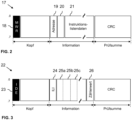
- Figure 2 shows a schematic representation of a first data packet 17 for programming a data bus participant 7a, 7b, ..., 7n without having to interrupt the ongoing communication.
- the first data packet 17 can be embedded in a sequence of data packets of the ongoing cyclic communication and used to program a data bus participant 7a, 7b, ..., 7n.
- the programming of one data bus participant 7a, 7b, ..., 7n takes place with the aid of instruction list information, which is sent in the first data packet 17 to the data bus participant 7a, 7b, ..., 7n to be programmed.
- the first data packet 17 consists of a general header, a Information section and a checksum section.
- the header section includes a field 18, which contains a unique, only-occurring bit pattern MWR, which can also be referred to as a code word or identifier.
- MWR unique, only-occurring bit pattern
- the data bus participants 7a, 7b, ..., 7n know that when the bit pattern MWR occurs, data will be made available to the data bus participants 7a, 7b, ..., 7n. This data can be the instruction lists for the data bus participants 7a, 7b, ..., 7n to program the data bus participants 7a, 7b, ..., 7n.
- the header of the first data packet 17 can also contain further information necessary for control or error detection - not shown here.
- the information part of the first data packet 17 contains a field 19 in which the address of the data bus participant 7a, 7b, ..., 7n to be addressed is stored. Only the data bus participant 7a, 7b, ..., 7n whose address matches the address stored in field 19 reads the instruction list data 21 of the information part of the first data packet 17.
- the information part can also have a further field 20, which can be used by the corresponding data bus participant 7a, 7b, ..., 7n whose address is stored in field 19 for error detection and error propagation, or this field 20 can contain instructions as to where the instruction list data 21 should be stored.
- the instruction list data 21 can contain at least one instruction list or multiple instruction lists.
- the instruction lists contain sets of instructions that define the processing to be performed by the data bus devices 7a, 7b, ..., 7n.
- the first data packet 17 can also contain a checksum portion with which a cyclic redundancy check can be performed.
- this data bus participant 7a, 7b, ..., 7n After a data bus participant 7a, 7b, ..., 7n has been programmed using the first data packet 17, i.e., as soon as the instruction list has been stored in the data bus participant 7a, 7b, ..., 7n, this data bus participant 7a, 7b, ..., 7n is ready to process process data.
- This process data can be received in the same cycle frame that accomplished the programming of the data bus participant 7a, 7b, ..., 7n, namely in a second data packet, which follows the first data packet in the cycle frame.
- Such a second data packet is Figure 3 shown.
- the second data packet 22 can also be received in a different cycle frame.
- Figure 3 shows a schematic representation of a second data packet 22 for sending process data to the data bus participants 7a, 7b, ..., 7n of the ring bus 6.
- the second data packet 22 can be embedded in a cycle frame of the ongoing communication, e.g. as part of the process data part.
- the second data packet 22 consists of a general header, an information part, and a checksum part.
- the header includes a field 23 containing a unique, only-occurring bit pattern IDE, which can also be referred to as a code word or identifier.
- IDE unique, only-occurring bit pattern
- the data bus nodes 7a, 7b, ..., 7n are aware that when the bit pattern IDE occurs, a process data packet is transmitted.
- the header of the second data packet 22 can further contain other information that can be used for control and/or troubleshooting.
- the information part of the second data packet 22 can first have an instruction list index field, ILI, 24, which specifies which instruction list the data bus nodes 7a, 7b, ..., 7n should use.
- first instruction list comprises instructions for process data in a first process data packet within a cycle frame
- second instruction list to comprise a second set of instructions for process data in a second process data packet within a cycle frame.
- the first arrangement can be different from the second arrangement.
- the first instruction list can be used, for example, before the tool change, whereas the second instruction list is used after the tool change.
- the instruction list index 24 can be set to the memory location of the data bus device.
- the instruction list index can have a value with which the data bus participant 7a, 7b, ..., 7n can find the corresponding instruction list, for example via a conversion table, so that according to the instruction list index 24 either a first or a second or another instruction list indicated by the instruction list index 24 can be used.
- the information portion of the second data packet 22 further includes the actual process data 25a, 25b, 25c, ....
- the process data 25a, 25b, 25c, ... are used at the data bus participants 7a, 7b, ..., 7n to perform control, regulation, or evaluation.
- the process data 25a, 25b, 25c, ... can, for example, be transmitted to actuators to trigger a positioning movement of the actuator.
- the process data 25a, 25b, 25c, ... can thus represent control signals or be converted into corresponding control signals by the data bus participants 7a, 7b, ..., 7n.
- the data bus devices 7a, 7b, ..., 7n can, for example, also represent measured values recorded by sensors connected to the data bus devices 7a, 7b, ..., 7n and can be used as limit or control values to control actuators accordingly.
- the data bus devices 7a, 7b, ..., 7n convert the process data 25a, 25b, 25c, ... into control signals and/or measurement signals, or vice versa.
- the second data packet 22 has a counter value 26, which is incremented or decremented by each data bus participant 7a, 7b, ..., 7n through which the second data packet 22 passes, so that when the second data packet 22 arrives again at the local bus master 3, or this part of the second data packet 22 arrives again at the local bus master 3, it can be determined whether all data bus participants 7a, 7b, ..., 7n have processed the cycle frame, which inherently also provides information about whether a data bus participant 7a, 7b, ..., 7n has an error and has not performed any processing. Furthermore, the second data packet 22 can also have a checksum part with which a cyclic redundancy check can be performed.
- Figure 4 shows an exemplary timing diagram of the forwarding of the first and second data packets 17, 22 through corresponding data bus participants 7a, 7b, ..., 7n of a Ring bus 6.
- the second data bus participant 7b is programmed with the aid of the first data packet 17.
- the data bus station 7a has forwarded the first symbol to the second data bus station 7b and received another symbol from the local bus master 3.
- the second data bus station 7b is also placed in receive mode, namely by receiving the symbol with the MWR bit pattern.
- all data bus stations 7a, 7b, ..., 7n are placed in receive mode.
- the first data bus subscriber 7a receives from the local bus master 3 a symbol of the first data packet 17, which contains a unique address of the data bus subscriber 7a, 7b, ... 7n to which the instruction list data 21 is directed.
- this symbol contains the information that the instruction list data 21 is intended for the second data bus subscriber 7b.
- the data bus subscriber 7a can exit its receive mode because it is known that the following instruction list data 21 is not intended for this data bus subscriber 7a. are. It is not relevant for the first data bus participant 7a for whom the instruction list data 21 are intended, but only that they are not intended for him, which results from the comparison.
- the first data bus station 7a has forwarded the symbol with the address to the second data bus station 7b.
- the second data bus station 7b has compared the unique address identified in the symbol with its own unique address and determined that there is a match. This means that the following instruction list data 21 is intended for the data bus station 7b.
- the data bus station 7b receives the instruction list data 21 in the following symbols, it is stored in an accessible memory. This means that the second data bus station 7b is programmed.
- the other data bus participants 7n through which the first data packet 17 runs symbol by symbol are indeed put into receive mode by the symbol with the MWR bit pattern, but a comparison with the following symbol carrying the address shows that the instruction list data 21 are not intended for these data bus participants 7n, so that they can leave receive mode again.
- the first data packet 17 is followed by the second data packet 22.
- This data packet 22 also passes through the ring bus 6, i.e. the data bus participants 7a, 7b, ..., 7n symbol by symbol.
- the first data bus participant 7a receives a symbol with the bit pattern IDE, which puts the data bus participant 7a into processing mode because this bit pattern indicates that the following symbols carry process data 25a, 25b, 25c, ....
- the received symbol with the bit pattern IDE is then passed on to the data bus participants 7b, ..., 7n to put them into processing mode.
- the symbol with the IDE bit pattern is followed by a symbol with an instruction list index, ILI.
- the instruction list index tells the data bus participant 7a which stored instruction list it should use to process the following process data 25a, 25b, 25c, .... This instruction list index is also passed through all Data bus nodes 7b, ..., 7n.
- this instruction list index can, for example, point to the instruction list just stored, which was received via the instruction list data 21 of the first data packet 17. It is therefore possible to program data bus node 7b in the same cycle frame and to use the programming directly afterwards to process process data 25a, 25b, 25c, ...
- first and second data packets 17, 22 which are sent in the same cycle frame
- first and second data packets 17, 22 can also be sent in different cycle frames, and that a cycle frame can also contain only one of the data packets 17, 22 shown.
- Figure 5 shows an example of processing process data 25a, 25b, 25c, ... using instruction lists 27a, 27b, 27n.
- the instruction lists 27a, 27b, 27n are represented as tables.
- the instruction list 27a is stored in the data bus participant 7a, the instruction list 27b in the data bus participant 7b, and the instruction list 27n in the data bus participant 7n.
- each row of the tables contains two instructions that can be executed with the symbol of the data packet currently pending on the data bus participant 7a, 7b, ..., 7n.
- those skilled in the art will be aware that even if only two instructions for two working cycles are shown here as an example, a different number of instructions per symbol can also be executed.
- instruction lists 27a, 27b, 27n can also have a separate instruction for each bit in the process data symbols 25a, 25b, 25c, ...
- the instruction lists 27a, 27b, 27n can also have a separate instruction for each bit in the process data symbols 25a, 25b, 25c, ...
- the first data bus participant 7a receives the symbol with the instruction list index 24, it searches for the appropriate instruction list according to the instruction list index 24.
- the data bus participant 7a has stored two instruction lists, namely instruction lists 27a' and 27a".
- the instruction list index 24 refers to the instruction list 27a', for example, to the memory location of the first instruction of the corresponding instruction list 27a'.
- the next symbol which carries the process data 25a
- the first instructions in the instruction list 27a' are executed.
- the first line of the instruction list 27a' of the data bus participant 7a is empty, which is marked with "---". This means that the data bus participant 7a does not perform any processing with the first received symbol because no instruction is present.
- the instruction list 27a' can also contain "SKIP" instructions at this point.
- the data bus station 7a For the next symbol, which carries the process data 25b, the data bus station 7a has no instructions in its instruction list 27a'. This means that this process data 25b is also not processed by the data bus station 7a, but remains there only for a certain time, for example, two working cycles, in order to ensure deterministic behavior of the ring bus 6, so that each data bus station 7a, 7b, ..., 7n has the same amount of time available for each symbol currently present.
- the data bus participant 7b in the embodiment shown here also has two instruction lists stored, namely instruction lists 27b' and 27b". At least one instruction list 27b', 27b" can be one that was previously communicated to the data bus participant 7b via the instruction list data 21 of the first data packet 17. This means that it can be one with which the data bus participant 7b was programmed directly before receiving the process data 25a, 25b, 25c, ...
- the instruction list 27b' contains in the first line the instruction Read "R”, namely the process data 25a from the first symbol reaching the data bus participant 7b after the symbol that Instruction list index 24.
- the second instruction is "Write" the just-read process data 25a into the memory at memory location 0000.
- the instruction list contains processing steps that are not directly related to the process data 25b carried by this symbol, but rather only utilize the time that the data bus node 7b has before it must forward the symbol.
- the instruction list 27b' contains the instructions to read the input 13 of the data bus node 7b, which is labeled "R," and to read the previously stored process data 25a from the memory. Reading the input can, for example, consist of reading a sensor value from a sensor 15 connected to the input 13.
- instruction list 27b' contains instructions to create a bitwise "AND" combination of the value read from input 13 and the process data 25a and to write this combination into the symbol, i.e., to overwrite process data 25c.
- the process data 25c can be overwritten because it has already been read by the first data bus station 7a and is no longer required by any other data bus station 7b, ..., 7n. In this way, the calculated value can be forwarded to the local bus master 3 or the controller 1.
- Those skilled in the art will be aware that other calculations or bit operations can also be performed here, and that the specified bit operations are for illustrative purposes only and are not to be understood as limiting.
- the data bus participant 7n can also have two instruction lists 27n' and 27n", with the instruction list index 24 indicating which of the instruction lists 27n' or 27n' is to be used.
- the instruction list index 24 instructs all data bus participants 7a, 7b, ..., 7n to use their first instruction list, i.e. the data bus participant 7n also uses its first instruction list, namely instruction list 27n'.
- this instruction list 27n' has only one instruction for the second symbol reaching this data bus participant 7n after the instruction list index 24, this instruction being read "R" process data 25b.
- the methods described herein may also be implemented as a computer-readable medium including code that causes a computer to perform at least one of the described methods.
- the computer-readable medium may be implemented in any manner and may be provided on a storage medium such as a DVD, CD, hard disk, or other storage media.
Landscapes
- Engineering & Computer Science (AREA)
- Computer Networks & Wireless Communication (AREA)
- Signal Processing (AREA)
- Theoretical Computer Science (AREA)
- Software Systems (AREA)
- Physics & Mathematics (AREA)
- General Engineering & Computer Science (AREA)
- General Physics & Mathematics (AREA)
- Computer Security & Cryptography (AREA)
- Small-Scale Networks (AREA)
Claims (8)
- Procédé de mise en œuvre d'un participant à un bus de données (7a, 7b, ..., 7n) d'un bus local (6), le procédé comportant :la réception d'un premier paquet de données (17) sur le bus local (6), dans lequel le premier paquet de données (17) comporte une adresse (19) du participant au bus de données (7a, 7b, ..., 7n) qui en est le destinataire, et au moins une liste d'instructions (27a, 27b, 27n) avec un ensemble d'instructions pour le traitement de données de processus (25a, 25b, 25c) ;la réception d'un symbole d'un deuxième paquet de données (22) sur le bus local (6), dans lequel le deuxième paquet de données (22) comporte des données de processus (25a, 25b, 25c), dans lequel le deuxième paquet de données (22) comporte un nombre de symboles ;l'exécution d'instructions de l'au moins une liste d'instructions (27a, 27b, 27n) pour le traitement symbole par symbole des données de processus (25a, 25b, 25c) reçues;le procédé étant caractérisé par :
le transfert du symbole traité du deuxième paquet de données (22) à un autre participant au bus de données (7a, 7b, ..., 7n) sur le bus local (6), et la réception simultanée d'un autre symbole du deuxième paquet de données (22), dans lequel le transfert est retardé de manière que chaque symbole reste toujours de même longueur au niveau du participant au bus de données (7a, 7b, ..., 7n). - Procédé selon la revendication 1, dans lequel le premier et le deuxième paquet de données (17, 22) sont des données utiles d'une trame de cycle ou de deux trames de cycle.
- Procédé selon l'une des revendications précédentes, dans lequel le premier paquet de données (17) comporte un certain nombre de symboles.
- Procédé selon l'une des revendications précédentes, dans lequel chaque symbole est traité avec un nombre fixe d'instructions de la liste d'instructions (27a, 27b, 27n).
- Procédé selon la revendication 4, dans lequel le traitement symbole par symbole des données de processus (25a, 25b, 25c) reçues comporte un traitement bit-granulaire des données de processus (25a, 25b, 25c) reçues.
- Procédé selon la revendication 5, dans lequel le traitement bit-granulaire comporte :
l'exécution d'une opération de bit sur au moins un bit du symbole reçu pour obtenir au moins une date de processus traitée. - Procédé selon l'une des revendications précédentes, dans lequel l'adresse est une adresse unique qui est utilisée pour la communication adressée avec le participant au bus de données (7a, 7b, ..., 7n).
- Participant à un bus de données (7a, 7b, ..., 7n) d'un bus local (6), le participant au bus de données (7a, 7b, ..., 7n) comportant :un moyen de réception d'un premier paquet de données (17) sur le bus local (6), dans lequel le premier paquet de données (17) comporte une adresse (19) du participant au bus de données (7a, 7b, ..., 7n) qui en est le destinataire, et au moins une liste d'instructions (27a, 27b, 27n) avec un ensemble d'instructions pour le traitement de données de processus (25a, 25b, 25c) ;un moyen de réception d'un symbole d'un deuxième paquet de données (22) sur le bus local (6), dans lequel le deuxième paquet de données (22) comporte des données de processus (25a, 25b, 25c), dans lequel le deuxième paquet de données (22) comporte un nombre de symboles ;un moyen d'exécution d'instructions de l'au moins une liste d'instructions (27a, 27b, 27n) pour le traitement des données de processus (25a, 25b, 25c) reçues ;le participant au bus de données étant caractérisé par :
des moyens de transfert du symbole traité du deuxième paquet de données (22) à un autre participant au bus de données (7a, 7b, ..., 7n) sur le bus local (6), et de réception simultanée d'un autre symbole du deuxième paquet de données (22) avec le moyen de réception, dans lequel le transfert est retardé de manière à ce que chaque symbole reste toujours de même longueur sur le participant au bus de données (7a, 7b, ..., 7n).
Applications Claiming Priority (2)
| Application Number | Priority Date | Filing Date | Title |
|---|---|---|---|
| DE102017208818.4A DE102017208818A1 (de) | 2017-05-24 | 2017-05-24 | Initialisierung von Datenbusteilnehmern |
| PCT/EP2018/062941 WO2018215295A1 (fr) | 2017-05-24 | 2018-05-17 | Initialisation d'abonnés de bus de données |
Publications (2)
| Publication Number | Publication Date |
|---|---|
| EP3632051A1 EP3632051A1 (fr) | 2020-04-08 |
| EP3632051B1 true EP3632051B1 (fr) | 2025-03-19 |
Family
ID=62222656
Family Applications (1)
| Application Number | Title | Priority Date | Filing Date |
|---|---|---|---|
| EP18726426.2A Active EP3632051B1 (fr) | 2017-05-24 | 2018-05-17 | Initialisation d'abonnés de bus de données |
Country Status (5)
| Country | Link |
|---|---|
| US (1) | US11736318B2 (fr) |
| EP (1) | EP3632051B1 (fr) |
| CN (1) | CN110663225B (fr) |
| DE (1) | DE102017208818A1 (fr) |
| WO (1) | WO2018215295A1 (fr) |
Citations (2)
| Publication number | Priority date | Publication date | Assignee | Title |
|---|---|---|---|---|
| US20150110126A1 (en) * | 2012-07-03 | 2015-04-23 | Freescale Semiconductor, Inc. | Cut through packet forwarding device |
| KR101576050B1 (ko) * | 2014-09-12 | 2015-12-11 | 한국전기연구원 | 복수 노드의 소프트웨어 업그레이드를 위한 방법, 이를 위한 장치 및 시스템 |
Family Cites Families (23)
| Publication number | Priority date | Publication date | Assignee | Title |
|---|---|---|---|---|
| US5165024A (en) * | 1990-04-12 | 1992-11-17 | Apple Computer, Inc. | Information transfer and receiving system with a ring interconnect architecture using voucher and ticket signals |
| US5457683A (en) * | 1993-05-07 | 1995-10-10 | Apple Computer, Inc. | Link and discovery protocols for a ring interconnect architecture |
| US5472347A (en) | 1993-09-17 | 1995-12-05 | Allen-Bradley Company, Inc. | System for interconnecting I/O modules for data communications over a common backplane |
| US6510141B1 (en) * | 1996-11-27 | 2003-01-21 | Dynarc Inc. Dha Dynamic Network Architecture Inc. | Link auto-configuration protocol specification topology |
| JPH10228421A (ja) | 1997-02-14 | 1998-08-25 | Nec Ic Microcomput Syst Ltd | メモリアクセス制御回路 |
| CA2255418C (fr) * | 1998-12-07 | 2003-01-21 | Pmc-Sierra Ltd. | Interface en anneau et systeme de commande de debit pour bus de reseau en anneau |
| CN1148647C (zh) * | 1999-08-30 | 2004-05-05 | Ip菲力股份有限公司 | 数据处理系统及其控制方法 |
| US20020004897A1 (en) * | 2000-07-05 | 2002-01-10 | Min-Cheng Kao | Data processing apparatus for executing multiple instruction sets |
| WO2002015517A2 (fr) * | 2000-08-16 | 2002-02-21 | Microchip Technology Incorporated | Configuration a distance de noeud de reseau par l'intermediaire de messages de reseau electronique (can) |
| US20020191603A1 (en) * | 2000-11-22 | 2002-12-19 | Yeshik Shin | Method and system for dynamic segmentation of communications packets |
| US20020084655A1 (en) | 2000-12-29 | 2002-07-04 | Abb Research Ltd. | System, method and computer program product for enhancing commercial value of electrical power produced from a renewable energy power production facility |
| US20030167348A1 (en) * | 2001-07-02 | 2003-09-04 | Globespanvirata, Inc. | Communications system using rings architecture |
| DE10337699B4 (de) * | 2003-08-16 | 2006-01-12 | Phoenix Contact Gmbh & Co. Kg | Verfahren und Vorrichtung zur Übertragung von Daten über ein Busnetz unter Verwendung des Broadcast-Prinzip |
| US8626882B2 (en) * | 2005-10-07 | 2014-01-07 | GM Global Technology Operations LLC | Reconfigurable communication for distributed embedded systems |
| US7539888B2 (en) * | 2006-03-31 | 2009-05-26 | Freescale Semiconductor, Inc. | Message buffer for a receiver apparatus on a communications bus |
| CN101178644B (zh) * | 2006-11-10 | 2012-01-25 | 上海海尔集成电路有限公司 | 一种基于复杂指令集计算机结构的微处理器架构 |
| US8782771B2 (en) | 2007-06-19 | 2014-07-15 | Rockwell Automation Technologies, Inc. | Real-time industrial firewall |
| US8122279B2 (en) * | 2008-04-21 | 2012-02-21 | Kabushiki Kaisha Toshiba | Multiphase clocking systems with ring bus architecture |
| US9444757B2 (en) * | 2009-04-27 | 2016-09-13 | Intel Corporation | Dynamic configuration of processing modules in a network communications processor architecture |
| US8291136B2 (en) * | 2009-12-02 | 2012-10-16 | International Business Machines Corporation | Ring buffer |
| US8824603B1 (en) * | 2013-03-01 | 2014-09-02 | Futurewei Technologies, Inc. | Bi-directional ring-bus architecture for CORDIC-based matrix inversion |
| CN105046913A (zh) * | 2015-07-09 | 2015-11-11 | 广西牛博物联信息技术有限公司 | 远程环境监测数据采集系统 |
| US9871674B2 (en) * | 2015-09-30 | 2018-01-16 | International Business Machines Corporation | Bridging between differing communication buses |
-
2017
- 2017-05-24 DE DE102017208818.4A patent/DE102017208818A1/de active Pending
-
2018
- 2018-05-17 CN CN201880034529.1A patent/CN110663225B/zh active Active
- 2018-05-17 EP EP18726426.2A patent/EP3632051B1/fr active Active
- 2018-05-17 WO PCT/EP2018/062941 patent/WO2018215295A1/fr not_active Ceased
-
2019
- 2019-11-25 US US16/693,964 patent/US11736318B2/en active Active
Patent Citations (2)
| Publication number | Priority date | Publication date | Assignee | Title |
|---|---|---|---|---|
| US20150110126A1 (en) * | 2012-07-03 | 2015-04-23 | Freescale Semiconductor, Inc. | Cut through packet forwarding device |
| KR101576050B1 (ko) * | 2014-09-12 | 2015-12-11 | 한국전기연구원 | 복수 노드의 소프트웨어 업그레이드를 위한 방법, 이를 위한 장치 및 시스템 |
Non-Patent Citations (2)
| Title |
|---|
| "Computer Networks, fifth edition", 7 October 2010, PRENTICE HALL, US, ISBN: 978-0-13-212695-3, article ANDREW S. TANENBAUM ET AL: "Computer Networks (5th Edition)", pages: 1-192,257 - 350,813-82, XP055509873 * |
| TENRUH MAHMUT ET AL: "DESIGN AND PERFORMANCE ANALYSIS OF CONTROLLER AREA NETWORK CUT- THROUGH BRIDGES KONTROL ALAN AGI DOGRUDAN GEÇiSLi KÖPRÜLERiNiN DiZAYNI VE PERFORMANS ANALiZi ÖZET", 1 January 2002 (2002-01-01), pages 267 - 272, XP055844973, Retrieved from the Internet <URL:http://acikerisim.mu.edu.tr/xmlui/bitstream/handle/20.500.12809/8257/tenruh.pdf?sequence=1&isAllowed=y> [retrieved on 20210927] * |
Also Published As
| Publication number | Publication date |
|---|---|
| CN110663225B (zh) | 2022-02-18 |
| DE102017208818A1 (de) | 2018-11-29 |
| WO2018215295A1 (fr) | 2018-11-29 |
| EP3632051A1 (fr) | 2020-04-08 |
| US20200092136A1 (en) | 2020-03-19 |
| US11736318B2 (en) | 2023-08-22 |
| CN110663225A (zh) | 2020-01-07 |
Similar Documents
| Publication | Publication Date | Title |
|---|---|---|
| EP3632040B1 (fr) | Traitement de données de processus | |
| EP4191954B1 (fr) | Unité modulaire permettant de connecter un abonné de bus de données | |
| EP3632050B1 (fr) | Convertisseur de données de bus | |
| EP3632054B1 (fr) | Determination de noeuds d'un bus de données local | |
| EP4236212B1 (fr) | Elément de base pour un abonné d'un bus de données | |
| EP3632056B1 (fr) | Intitialisation d'un bus local | |
| EP3972205B1 (fr) | Traitement des données de processus | |
| EP3632051B1 (fr) | Initialisation d'abonnés de bus de données | |
| EP3631630B1 (fr) | Traitement distribué de données de processus | |
| EP3632055B1 (fr) | Transmission de données sur un bus local | |
| EP3632066B1 (fr) | Préchargement d'instructions | |
| DE102017012250B4 (de) | Übertragen von Daten auf einem Lokalbus | |
| DE10004426A1 (de) | Netzwerkteilnehmer, insbesondere Feldgerät, sowie Netzwerk mit einem derartigen Netzwerkteilnehmer |
Legal Events
| Date | Code | Title | Description |
|---|---|---|---|
| STAA | Information on the status of an ep patent application or granted ep patent |
Free format text: STATUS: UNKNOWN |
|
| STAA | Information on the status of an ep patent application or granted ep patent |
Free format text: STATUS: THE INTERNATIONAL PUBLICATION HAS BEEN MADE |
|
| PUAI | Public reference made under article 153(3) epc to a published international application that has entered the european phase |
Free format text: ORIGINAL CODE: 0009012 |
|
| STAA | Information on the status of an ep patent application or granted ep patent |
Free format text: STATUS: REQUEST FOR EXAMINATION WAS MADE |
|
| 17P | Request for examination filed |
Effective date: 20191112 |
|
| AK | Designated contracting states |
Kind code of ref document: A1 Designated state(s): AL AT BE BG CH CY CZ DE DK EE ES FI FR GB GR HR HU IE IS IT LI LT LU LV MC MK MT NL NO PL PT RO RS SE SI SK SM TR |
|
| AX | Request for extension of the european patent |
Extension state: BA ME |
|
| DAV | Request for validation of the european patent (deleted) | ||
| DAX | Request for extension of the european patent (deleted) | ||
| STAA | Information on the status of an ep patent application or granted ep patent |
Free format text: STATUS: EXAMINATION IS IN PROGRESS |
|
| 17Q | First examination report despatched |
Effective date: 20211001 |
|
| P01 | Opt-out of the competence of the unified patent court (upc) registered |
Effective date: 20230522 |
|
| RAP3 | Party data changed (applicant data changed or rights of an application transferred) |
Owner name: WAGO VERWALTUNGSGESELLSCHAFT MBH |
|
| RAP3 | Party data changed (applicant data changed or rights of an application transferred) |
Owner name: WAGO VERWALTUNGSGESELLSCHAFT MBH |
|
| GRAP | Despatch of communication of intention to grant a patent |
Free format text: ORIGINAL CODE: EPIDOSNIGR1 |
|
| STAA | Information on the status of an ep patent application or granted ep patent |
Free format text: STATUS: GRANT OF PATENT IS INTENDED |
|
| RIC1 | Information provided on ipc code assigned before grant |
Ipc: H04L 41/0803 20220101ALI20241220BHEP Ipc: H04L 12/423 20060101ALI20241220BHEP Ipc: H04L 12/40 20060101AFI20241220BHEP |
|
| GRAS | Grant fee paid |
Free format text: ORIGINAL CODE: EPIDOSNIGR3 |
|
| INTG | Intention to grant announced |
Effective date: 20250114 |
|
| GRAA | (expected) grant |
Free format text: ORIGINAL CODE: 0009210 |
|
| STAA | Information on the status of an ep patent application or granted ep patent |
Free format text: STATUS: THE PATENT HAS BEEN GRANTED |
|
| REG | Reference to a national code |
Ref country code: DE Ref legal event code: R081 Ref document number: 502018015663 Country of ref document: DE Owner name: WAGO VERWALTUNGSGESELLSCHAFT MIT BESCHRAENKTER, DE Free format text: FORMER OWNER: WAGO VERWALTUNGSGESELLSCHAFT MBH, 32423 MINDEN, DE |
|
| AK | Designated contracting states |
Kind code of ref document: B1 Designated state(s): AL AT BE BG CH CY CZ DE DK EE ES FI FR GB GR HR HU IE IS IT LI LT LU LV MC MK MT NL NO PL PT RO RS SE SI SK SM TR |
|
| REG | Reference to a national code |
Ref country code: GB Ref legal event code: FG4D Free format text: NOT ENGLISH |
|
| REG | Reference to a national code |
Ref country code: CH Ref legal event code: EP |
|
| REG | Reference to a national code |
Ref country code: DE Ref legal event code: R096 Ref document number: 502018015663 Country of ref document: DE |
|
| REG | Reference to a national code |
Ref country code: IE Ref legal event code: FG4D Free format text: LANGUAGE OF EP DOCUMENT: GERMAN |
|
| PG25 | Lapsed in a contracting state [announced via postgrant information from national office to epo] |
Ref country code: RS Free format text: LAPSE BECAUSE OF FAILURE TO SUBMIT A TRANSLATION OF THE DESCRIPTION OR TO PAY THE FEE WITHIN THE PRESCRIBED TIME-LIMIT Effective date: 20250619 |
|
| PG25 | Lapsed in a contracting state [announced via postgrant information from national office to epo] |
Ref country code: FI Free format text: LAPSE BECAUSE OF FAILURE TO SUBMIT A TRANSLATION OF THE DESCRIPTION OR TO PAY THE FEE WITHIN THE PRESCRIBED TIME-LIMIT Effective date: 20250319 |
|
| PGFP | Annual fee paid to national office [announced via postgrant information from national office to epo] |
Ref country code: DE Payment date: 20250528 Year of fee payment: 8 |
|
| REG | Reference to a national code |
Ref country code: LT Ref legal event code: MG9D |
|
| PG25 | Lapsed in a contracting state [announced via postgrant information from national office to epo] |
Ref country code: NO Free format text: LAPSE BECAUSE OF FAILURE TO SUBMIT A TRANSLATION OF THE DESCRIPTION OR TO PAY THE FEE WITHIN THE PRESCRIBED TIME-LIMIT Effective date: 20250619 |
|
| PG25 | Lapsed in a contracting state [announced via postgrant information from national office to epo] |
Ref country code: HR Free format text: LAPSE BECAUSE OF FAILURE TO SUBMIT A TRANSLATION OF THE DESCRIPTION OR TO PAY THE FEE WITHIN THE PRESCRIBED TIME-LIMIT Effective date: 20250319 |
|
| PG25 | Lapsed in a contracting state [announced via postgrant information from national office to epo] |
Ref country code: LV Free format text: LAPSE BECAUSE OF FAILURE TO SUBMIT A TRANSLATION OF THE DESCRIPTION OR TO PAY THE FEE WITHIN THE PRESCRIBED TIME-LIMIT Effective date: 20250319 |
|
| PGFP | Annual fee paid to national office [announced via postgrant information from national office to epo] |
Ref country code: FR Payment date: 20250526 Year of fee payment: 8 |
|
| PG25 | Lapsed in a contracting state [announced via postgrant information from national office to epo] |
Ref country code: GR Free format text: LAPSE BECAUSE OF FAILURE TO SUBMIT A TRANSLATION OF THE DESCRIPTION OR TO PAY THE FEE WITHIN THE PRESCRIBED TIME-LIMIT Effective date: 20250620 Ref country code: BG Free format text: LAPSE BECAUSE OF FAILURE TO SUBMIT A TRANSLATION OF THE DESCRIPTION OR TO PAY THE FEE WITHIN THE PRESCRIBED TIME-LIMIT Effective date: 20250319 |
|
| PGFP | Annual fee paid to national office [announced via postgrant information from national office to epo] |
Ref country code: AT Payment date: 20250520 Year of fee payment: 8 |
|
| REG | Reference to a national code |
Ref country code: NL Ref legal event code: MP Effective date: 20250319 |
|
| PG25 | Lapsed in a contracting state [announced via postgrant information from national office to epo] |
Ref country code: NL Free format text: LAPSE BECAUSE OF FAILURE TO SUBMIT A TRANSLATION OF THE DESCRIPTION OR TO PAY THE FEE WITHIN THE PRESCRIBED TIME-LIMIT Effective date: 20250319 |
|
| PG25 | Lapsed in a contracting state [announced via postgrant information from national office to epo] |
Ref country code: SE Free format text: LAPSE BECAUSE OF FAILURE TO SUBMIT A TRANSLATION OF THE DESCRIPTION OR TO PAY THE FEE WITHIN THE PRESCRIBED TIME-LIMIT Effective date: 20250319 |
|
| PG25 | Lapsed in a contracting state [announced via postgrant information from national office to epo] |
Ref country code: SM Free format text: LAPSE BECAUSE OF FAILURE TO SUBMIT A TRANSLATION OF THE DESCRIPTION OR TO PAY THE FEE WITHIN THE PRESCRIBED TIME-LIMIT Effective date: 20250319 |
|
| PG25 | Lapsed in a contracting state [announced via postgrant information from national office to epo] |
Ref country code: ES Free format text: LAPSE BECAUSE OF FAILURE TO SUBMIT A TRANSLATION OF THE DESCRIPTION OR TO PAY THE FEE WITHIN THE PRESCRIBED TIME-LIMIT Effective date: 20250319 Ref country code: PT Free format text: LAPSE BECAUSE OF FAILURE TO SUBMIT A TRANSLATION OF THE DESCRIPTION OR TO PAY THE FEE WITHIN THE PRESCRIBED TIME-LIMIT Effective date: 20250721 |
|
| PG25 | Lapsed in a contracting state [announced via postgrant information from national office to epo] |
Ref country code: PL Free format text: LAPSE BECAUSE OF FAILURE TO SUBMIT A TRANSLATION OF THE DESCRIPTION OR TO PAY THE FEE WITHIN THE PRESCRIBED TIME-LIMIT Effective date: 20250319 Ref country code: IT Free format text: LAPSE BECAUSE OF FAILURE TO SUBMIT A TRANSLATION OF THE DESCRIPTION OR TO PAY THE FEE WITHIN THE PRESCRIBED TIME-LIMIT Effective date: 20250319 |
|
| PG25 | Lapsed in a contracting state [announced via postgrant information from national office to epo] |
Ref country code: CZ Free format text: LAPSE BECAUSE OF FAILURE TO SUBMIT A TRANSLATION OF THE DESCRIPTION OR TO PAY THE FEE WITHIN THE PRESCRIBED TIME-LIMIT Effective date: 20250319 Ref country code: EE Free format text: LAPSE BECAUSE OF FAILURE TO SUBMIT A TRANSLATION OF THE DESCRIPTION OR TO PAY THE FEE WITHIN THE PRESCRIBED TIME-LIMIT Effective date: 20250319 |
|
| PG25 | Lapsed in a contracting state [announced via postgrant information from national office to epo] |
Ref country code: RO Free format text: LAPSE BECAUSE OF FAILURE TO SUBMIT A TRANSLATION OF THE DESCRIPTION OR TO PAY THE FEE WITHIN THE PRESCRIBED TIME-LIMIT Effective date: 20250319 |
|
| PG25 | Lapsed in a contracting state [announced via postgrant information from national office to epo] |
Ref country code: SK Free format text: LAPSE BECAUSE OF FAILURE TO SUBMIT A TRANSLATION OF THE DESCRIPTION OR TO PAY THE FEE WITHIN THE PRESCRIBED TIME-LIMIT Effective date: 20250319 |
|
| PG25 | Lapsed in a contracting state [announced via postgrant information from national office to epo] |
Ref country code: IS Free format text: LAPSE BECAUSE OF FAILURE TO SUBMIT A TRANSLATION OF THE DESCRIPTION OR TO PAY THE FEE WITHIN THE PRESCRIBED TIME-LIMIT Effective date: 20250719 |
|
| REG | Reference to a national code |
Ref country code: DE Ref legal event code: R097 Ref document number: 502018015663 Country of ref document: DE |
|
| REG | Reference to a national code |
Ref country code: CH Ref legal event code: H13 Free format text: ST27 STATUS EVENT CODE: U-0-0-H10-H13 (AS PROVIDED BY THE NATIONAL OFFICE) Effective date: 20251223 |
|
| PG25 | Lapsed in a contracting state [announced via postgrant information from national office to epo] |
Ref country code: DK Free format text: LAPSE BECAUSE OF FAILURE TO SUBMIT A TRANSLATION OF THE DESCRIPTION OR TO PAY THE FEE WITHIN THE PRESCRIBED TIME-LIMIT Effective date: 20250319 |
|
| PG25 | Lapsed in a contracting state [announced via postgrant information from national office to epo] |
Ref country code: LU Free format text: LAPSE BECAUSE OF NON-PAYMENT OF DUE FEES Effective date: 20250517 |
|
| PG25 | Lapsed in a contracting state [announced via postgrant information from national office to epo] |
Ref country code: CH Free format text: LAPSE BECAUSE OF NON-PAYMENT OF DUE FEES Effective date: 20250531 |
|
| PLBE | No opposition filed within time limit |
Free format text: ORIGINAL CODE: 0009261 |
|
| STAA | Information on the status of an ep patent application or granted ep patent |
Free format text: STATUS: NO OPPOSITION FILED WITHIN TIME LIMIT |
|
| REG | Reference to a national code |
Ref country code: CH Ref legal event code: L10 Free format text: ST27 STATUS EVENT CODE: U-0-0-L10-L00 (AS PROVIDED BY THE NATIONAL OFFICE) Effective date: 20260128 |
|
| REG | Reference to a national code |
Ref country code: BE Ref legal event code: MM Effective date: 20250531 |
|
| PG25 | Lapsed in a contracting state [announced via postgrant information from national office to epo] |
Ref country code: MC Free format text: LAPSE BECAUSE OF FAILURE TO SUBMIT A TRANSLATION OF THE DESCRIPTION OR TO PAY THE FEE WITHIN THE PRESCRIBED TIME-LIMIT Effective date: 20250319 |
|
| 26N | No opposition filed |
Effective date: 20251222 |
|
| GBPC | Gb: european patent ceased through non-payment of renewal fee |
Effective date: 20250619 |
|
| PG25 | Lapsed in a contracting state [announced via postgrant information from national office to epo] |
Ref country code: GB Free format text: LAPSE BECAUSE OF NON-PAYMENT OF DUE FEES Effective date: 20250619 |
|
| PG25 | Lapsed in a contracting state [announced via postgrant information from national office to epo] |
Ref country code: IE Free format text: LAPSE BECAUSE OF NON-PAYMENT OF DUE FEES Effective date: 20250517 |
|
| PG25 | Lapsed in a contracting state [announced via postgrant information from national office to epo] |
Ref country code: BE Free format text: LAPSE BECAUSE OF NON-PAYMENT OF DUE FEES Effective date: 20250531 |