EP3731596A2 - Échangeur de chaleur spirale - Google Patents
Échangeur de chaleur spirale Download PDFInfo
- Publication number
- EP3731596A2 EP3731596A2 EP20169807.3A EP20169807A EP3731596A2 EP 3731596 A2 EP3731596 A2 EP 3731596A2 EP 20169807 A EP20169807 A EP 20169807A EP 3731596 A2 EP3731596 A2 EP 3731596A2
- Authority
- EP
- European Patent Office
- Prior art keywords
- housing
- heating element
- flow channel
- wall
- channel section
- Prior art date
- Legal status (The legal status is an assumption and is not a legal conclusion. Google has not performed a legal analysis and makes no representation as to the accuracy of the status listed.)
- Granted
Links
Images


Classifications
-
- H—ELECTRICITY
- H05—ELECTRIC TECHNIQUES NOT OTHERWISE PROVIDED FOR
- H05B—ELECTRIC HEATING; ELECTRIC LIGHT SOURCES NOT OTHERWISE PROVIDED FOR; CIRCUIT ARRANGEMENTS FOR ELECTRIC LIGHT SOURCES, IN GENERAL
- H05B3/00—Ohmic-resistance heating
- H05B3/40—Heating elements having the shape of rods or tubes
- H05B3/54—Heating elements having the shape of rods or tubes flexible
- H05B3/56—Heating cables
- H05B3/565—Heating cables flat cables
-
- F—MECHANICAL ENGINEERING; LIGHTING; HEATING; WEAPONS; BLASTING
- F24—HEATING; RANGES; VENTILATING
- F24H—FLUID HEATERS, e.g. WATER OR AIR HEATERS, HAVING HEAT-GENERATING MEANS, e.g. HEAT PUMPS, IN GENERAL
- F24H1/00—Water heaters, e.g. boilers, continuous-flow heaters or water-storage heaters
- F24H1/10—Continuous-flow heaters, i.e. heaters in which heat is generated only while the water is flowing, e.g. with direct contact of the water with the heating medium
- F24H1/101—Continuous-flow heaters, i.e. heaters in which heat is generated only while the water is flowing, e.g. with direct contact of the water with the heating medium using electric energy supply
- F24H1/102—Continuous-flow heaters, i.e. heaters in which heat is generated only while the water is flowing, e.g. with direct contact of the water with the heating medium using electric energy supply with resistance
- F24H1/103—Continuous-flow heaters, i.e. heaters in which heat is generated only while the water is flowing, e.g. with direct contact of the water with the heating medium using electric energy supply with resistance with bare resistances in direct contact with the fluid
-
- F—MECHANICAL ENGINEERING; LIGHTING; HEATING; WEAPONS; BLASTING
- F24—HEATING; RANGES; VENTILATING
- F24H—FLUID HEATERS, e.g. WATER OR AIR HEATERS, HAVING HEAT-GENERATING MEANS, e.g. HEAT PUMPS, IN GENERAL
- F24H9/00—Details
- F24H9/20—Arrangement or mounting of control or safety devices
- F24H9/2007—Arrangement or mounting of control or safety devices for water heaters
- F24H9/2014—Arrangement or mounting of control or safety devices for water heaters using electrical energy supply
- F24H9/2028—Continuous-flow heaters
-
- H—ELECTRICITY
- H05—ELECTRIC TECHNIQUES NOT OTHERWISE PROVIDED FOR
- H05B—ELECTRIC HEATING; ELECTRIC LIGHT SOURCES NOT OTHERWISE PROVIDED FOR; CIRCUIT ARRANGEMENTS FOR ELECTRIC LIGHT SOURCES, IN GENERAL
- H05B3/00—Ohmic-resistance heating
- H05B3/10—Heating elements characterised by the composition or nature of the materials or by the arrangement of the conductor
- H05B3/18—Heating elements characterised by the composition or nature of the materials or by the arrangement of the conductor the conductor being embedded in an insulating material
-
- H—ELECTRICITY
- H05—ELECTRIC TECHNIQUES NOT OTHERWISE PROVIDED FOR
- H05B—ELECTRIC HEATING; ELECTRIC LIGHT SOURCES NOT OTHERWISE PROVIDED FOR; CIRCUIT ARRANGEMENTS FOR ELECTRIC LIGHT SOURCES, IN GENERAL
- H05B3/00—Ohmic-resistance heating
- H05B3/20—Heating elements having extended surface area substantially in a two-dimensional [2D] plane, e.g. plate-heater
- H05B3/34—Heating elements having extended surface area substantially in a two-dimensional [2D] plane, e.g. plate-heater flexible, e.g. heating nets or webs
- H05B3/36—Heating elements having extended surface area substantially in a two-dimensional [2D] plane, e.g. plate-heater flexible, e.g. heating nets or webs heating conductor embedded in insulating material
-
- F—MECHANICAL ENGINEERING; LIGHTING; HEATING; WEAPONS; BLASTING
- F24—HEATING; RANGES; VENTILATING
- F24H—FLUID HEATERS, e.g. WATER OR AIR HEATERS, HAVING HEAT-GENERATING MEANS, e.g. HEAT PUMPS, IN GENERAL
- F24H1/00—Water heaters, e.g. boilers, continuous-flow heaters or water-storage heaters
- F24H1/10—Continuous-flow heaters, i.e. heaters in which heat is generated only while the water is flowing, e.g. with direct contact of the water with the heating medium
- F24H1/101—Continuous-flow heaters, i.e. heaters in which heat is generated only while the water is flowing, e.g. with direct contact of the water with the heating medium using electric energy supply
- F24H1/102—Continuous-flow heaters, i.e. heaters in which heat is generated only while the water is flowing, e.g. with direct contact of the water with the heating medium using electric energy supply with resistance
-
- H—ELECTRICITY
- H05—ELECTRIC TECHNIQUES NOT OTHERWISE PROVIDED FOR
- H05B—ELECTRIC HEATING; ELECTRIC LIGHT SOURCES NOT OTHERWISE PROVIDED FOR; CIRCUIT ARRANGEMENTS FOR ELECTRIC LIGHT SOURCES, IN GENERAL
- H05B2203/00—Aspects relating to Ohmic resistive heating covered by group H05B3/00
- H05B2203/02—Heaters using heating elements having a positive temperature coefficient
-
- H—ELECTRICITY
- H05—ELECTRIC TECHNIQUES NOT OTHERWISE PROVIDED FOR
- H05B—ELECTRIC HEATING; ELECTRIC LIGHT SOURCES NOT OTHERWISE PROVIDED FOR; CIRCUIT ARRANGEMENTS FOR ELECTRIC LIGHT SOURCES, IN GENERAL
- H05B2203/00—Aspects relating to Ohmic resistive heating covered by group H05B3/00
- H05B2203/021—Heaters specially adapted for heating liquids
Definitions
- the invention relates to a device for heating a fluid by means of electrical energy, wherein a cylindrical housing is provided with an inlet and an outlet for the fluid, and the inlet is connected to the outlet via a flow channel for the fluid that runs inside the housing around the cylinder axis of the housing with decreasing distance from the cylinder axis inwardly winding spiral flow channel section, which is formed by a wall arranged vertically between a cover plate and a bottom plate of the housing, which is provided with an electrical heating element designed as a web-shaped heating element for heating the flowing fluid , according to the preamble of claim 1.
- Devices of the type mentioned are about from CH 101971 A known.
- the liquid flowing in via a central inlet is directed to the periphery of an inwardly winding spiral-shaped flow channel, which feeds the liquid to be heated to the interior of the device, where a sheet-shaped resistance element is attached to the innermost winding sections of the spiral-shaped flow channel and heats the liquid.
- the spiral-shaped flow channel finally opens into a central outlet through which the heated liquid leaves the device.
- the disadvantage of such devices lies on the one hand in the low efficiency of the device and on the other hand in the lack of operational reliability. If the thermal energy formed by the resistance element is not sufficiently dissipated by the flowing liquid, the resistance element is heated up, which can lead to the destruction of the heating element. It must therefore be ensured, for example, that the heating element is only switched on when the liquid is flowing, which is correspondingly complex in terms of control technology.
- a heating device for windshield washer fluids is known in which the windshield washer fluid is fed to an inwardly winding spiral flow channel.
- the flow channel has a top plate and a bottom plate provided, which have a heating element provided with PTC resistance elements, which is controlled by a thermostat.
- the resistance elements represent an electrical resistance in which electricity is converted into heat.
- PTC resistance elements which are also referred to as PTC thermistors, have the property of increasing electrical resistance with increasing temperature.
- the PTC resistance elements are used to heat up the windscreen washer fluid in seconds, whereby they are regulated to a higher temperature than that of the windscreen washer fluid.
- the DE 19837923 C1 describes a device for the sterilization of liquids, in which the liquid to be sterilized is fed to an inwardly winding spiral-shaped flow channel which feeds the liquid to be sterilized to the interior of the device, where an electrical heating element is arranged which heats the liquid. The heated and thus sterilized liquid is subsequently cooled down again via an outwardly winding flow channel and released as a cooled, sterilized liquid.
- the DE 29618194 U1 describes a spiral heat exchanger in which a first liquid is fed to an inwardly winding spiral-shaped flow channel which opens into a central outlet via which the first liquid leaves the device. Furthermore, a second liquid is fed to an outwardly winding spiral-shaped flow channel which opens into an outlet via which the second liquid leaves the device.
- the thermal energy of the first liquid can be transferred to the second liquid. It is therefore a heat exchanger for the transfer of thermal energy.
- An electrical heating element for heating a liquid is not provided.
- the KR 100762010 B1 shows a heating mat with an inductively heated liquid which is fed to a channel running in a spiral in the heating mat, the inlet and outlet of which end in the inductive heating device.
- the aim of the invention is therefore to provide a device for heating a fluid by means of electrical energy, which has a compact design and not only enables the fluid to be heated quickly, but can also be operated with a higher degree of efficiency compared to known devices. Furthermore, a high level of operational safety should be guaranteed.
- Claim 1 relates to a device for heating a fluid by means of electrical energy, wherein a cylindrical housing is provided with an inlet and an outlet for the fluid, and the inlet is connected to the outlet via a flow channel for the fluid running inside the housing, which has a spiral-shaped flow channel section which winds inwardly around the cylinder axis of the housing with decreasing distance to the cylinder axis, which is formed by a wall arranged vertically between a cover plate and a bottom plate of the housing, which is equipped with an electrical heating element designed as a web-shaped heating element for heating the flowing fluid is provided.
- the wall additionally forms a spiral flow channel section which winds outwards around the cylinder axis of the housing with increasing distance from the cylinder axis, the wall in a central area of the interior of the housing enclosing an end area closing off the inwardly winding flow channel section, which into the outlet opens, as well as an end area closing off the outward winding flow channel section, into which the inlet opens, and the outward winding flow channel section in a section of the wall closest to the inner wall of the housing opens into the inward winding flow channel section via a reversal area formed by a free end of the wall , wherein the wall is formed by the heating element in the form of a web, which is provided with PTC resistance elements, and as an interface between the outward winding flow channel section and the inwardly winding flow channel section.
- the liquid to be heated is fed to the device according to the invention via the inlet which opens into the end region of the outward winding flow channel section.
- the liquid thus flows from the central area of the housing into the peripheral areas of the interior of the housing, being heated by a surface of the web-shaped heating element which faces this outwardly winding flow channel section and which forms the wall of this flow channel section.
- the outward winding flow channel section opens in a section of the wall closest to the housing inner wall via a reversal region formed by a free end of the wall into the inward winding flow channel section.
- the liquid thus flows back from the peripheral areas of the interior of the housing into the central area of the housing, wherein it is further heated by a surface of the same web-shaped heating element facing the inwardly winding flow channel section.
- the inwardly winding flow channel section ends in the central area of the housing in an end area which opens into the outlet. Since the wall formed by the web-like heating element is designed as an interface between the inwardly winding flow channel section and the outwardly winding flow channel section, the liquid flows around both surfaces of the same heating element.
- the temperature difference between the liquid introduced into the central area via the inlet and the liquid discharged via the outlet, which is also located in the central area, is maximum.
- the temperature difference between the liquid flowing on both sides of the heating element is thus also maximal, specifically in that section of the heating element which is arranged in the central region of the housing. In the peripheral areas of the inward and outward winding flow channel sections, on the other hand, the temperature difference between the liquid flowing on both sides of the heating element is minimal.
- Is the mean value of the temperature on both sides of the heating element In contrast, almost constant over the entire course of the heating element. This ensures over the entire length of the web-shaped heating element that the temperature within the heating element provided with PTC resistance elements is approximately constant and the internal ohmic resistance of the PTC resistance elements per unit length is thus approximately constant over the length, which results in a uniform electrical power output in With regard to the temperature-dependent PTC resistance characteristic. In the reversal area at the free end of the wall, the temperature of the fluid reaches approximately half the desired temperature increase between the inlet and outlet temperature.
- the heating output emitted by the heating element along the flow path from the inlet to the reversal area should also correspond to half of the heating output provided for the entire flow path from the inlet to the outlet. Since the mean temperature value caused by the fluid is constant at every point of the heating element, the undesired effect of a reduction in the heating power due to the PTC characteristic is eliminated, whereby the possible heating power of the device can be increased drastically in a given installation space and the efficiency is optimized.
- the inside of the housing is ideally used due to the maximized heated surface and the heat transfer to the fluid flowing through is optimized. In this way, compact structural designs are made possible.
- a specific structural design provides that the heating element, which is designed in web form, crosses the housing jacket in a first end section via a fluid-tight, slot-shaped fastening area and forms a first end of the heating element that has electrical connections and is arranged outside the housing, and the inside in a second end section the housing arranged, free end of the wall forms.
- the tightness can be ensured, for example, by potting the fastening area with potting compound or adhesive.
- the heating element which is designed in the form of a web, can also be fastened with its long sides in grooves in the cover plate and the base plate of the housing.
- the free end of the web-shaped heating element arranged inside the housing is provided with a stabilizing rod which is attached to the cover plate and the base plate of the housing.
- the heating element consists in a known manner of a web-shaped substrate (preferably made of plastic), a heat distribution layer made of metal, electrodes and a heating layer made of PTC resistance elements, for example carbon pastes or ceramic layers, which act as an ohmic resistance and are applied using the screen printing process.
- the heating element can be insulated from the outside by a dielectric cover film.
- the PTC material of the PTC resistance elements is characterized by a strongly non-linear characteristic curve, in that the electrical resistance of the material increases with increasing temperature (caused by operation or passive heating) and the material finally increases at the material-specific cut-off temperature becomes high resistance. As a result, the electrical heating output decreases and there is no further heating. This also applies to local thermal inhomogeneities such as Air inclusions in the fluid.
- the heating element used is self-regulating and cannot overheat.
- the PTC material of the PTC resistance elements enables particularly rapid heating compared to conventional resistance materials.
- the web-like heating element is designed as a heating film which is folded around its longitudinal axis and around its transverse axis to form the wall.
- the heat distribution layer which is arranged on one side, is now on the outside on both sides of the heating element and faces the respective flow channel section.
- the substrate of the heating foil forms a separating one Layer between the electrically conductive layers in the form of the electrodes and the heating layer and the fluid, which reduces the risk of short circuits.
- the front sides come to lie along the two broad sides of the heating film on the same side, which can now be arranged outside the housing. There are therefore no cut edges on the heating foil that would be exposed to the fluid, so that a short circuit is again prevented.
- the inlet and the outlet are arranged on different sides of the housing. This arrangement makes it easier to couple several devices in series in order to achieve a higher heating output overall in this way. In order to heat a larger volume of fluid, several devices can also be arranged in parallel.
- Fig. 1 Reference is made to explain the course of the flow channel sections 1a, 1b within a housing 2 of the device.
- the liquid to be heated is supplied via an inlet 3 which is arranged in the central area of the interior of the housing and which opens into the end area of an outwardly winding flow channel section 1a.
- the liquid thus flows from the central area of the housing 2 into the peripheral areas of the interior of the housing, being heated by a surface of the web-shaped heating element 4 facing this outwardly winding flow channel section 1a, which forms the wall of this flow channel section 1a.
- the outwardly winding flow channel section 1a opens in a section of the wall closest to the housing inner wall via a reversal area formed by a free end of the web-shaped heating element 4 into the inwardly winding flow channel section 1b.
- the liquid thus flows back from the peripheral areas of the interior of the housing into the central area of the housing 2, being further heated by a surface of the same web-shaped heating element 4 facing the inwardly winding flow channel section 1b.
- the inwardly winding flow channel section 1b ends in the central area of the housing 2 finally in an end area which leads into the outlet 5 (in the Fig. 1 for a better understanding drawn in dashed lines) opens. Since the wall formed by the web-shaped heating element 4 is designed as an interface between the outwardly winding flow channel section 1a and the inwardly winding flow channel section 1b, the liquid flows around both surfaces of the same heating element 4.
- the flow path shown thus directs the cool fluid entering centrally through the inlet 3 along the flow channel section 1a formed by the heating element 4, which is arranged in a spiral shape, to the outside, where it is deflected and again along a path between the paths through which the flow passes first, second Flow channel section 1b flows inward and emerges again from housing 2 through outlet 5. Since the wall is formed from the heating element 4, the fluid is heated when the heating element 4 is switched on and thus gives off its heat to the fluid.
- the PTC effect of the PTC resistance elements of the heating element 4 would in itself cause the electrical resistance of the heating element 4 to rise in the outer areas of the spiral-shaped heating element 4 due to the higher temperature of the fluid and the heating power to decrease, which is contrary to the aim of as strong as possible heating of the fluid flowing through the housing 2 along the entire flow path.
- the flow channel 1 proposed according to the invention now makes it possible in an advantageous manner that fluids with temperatures whose average is constant in each case are located on both sides of the spiral-shaped heating element 4 at every point.
- the coolest fluid is located in the area of the inflow point, while the hottest fluid is located on the other side of the heating element 4 because it has already flowed through the entire flow path and has therefore absorbed the maximum heating power.
- the average of the two temperatures largely corresponds to the temperature in the deflection area of the flow path, where the cool fluid has flowed through approximately half of the flow path and thus has absorbed approximately half of the heating power. Since the average temperature resulting from the fluid is constant at every point on the heating element 4, the undesired effect of a reduction in the heating power due to the PTC effect is eliminated, which drastically increases the possible heating power of the device in a given installation space.
- FIG. 2 shows first a perspective view of an embodiment of the device according to Fig. 1 with base plate 2B and inserted heating element 4, but without cover plate 2D and housing jacket 2M.
- the heating element 4 which is in the form of a web, is fastened with one of its two longitudinal sides in a spiral-shaped groove in the base plate 2B of the housing 2.
- a first end section 4.1 of the web-shaped heating element 4 is arranged outside of the housing 2. At this first end section 4.1 the electrical connections of the heating element 4 are located. Furthermore, an opening in the base plate 2B for the inlet 3 can be seen.
- inlet 3 and outlet 5 is arbitrary, however, since the device can be operated in both directions, so that the inlet 3 can also be arranged in the cover plate 2D and the outlet 5 in the base plate 2B. In addition, both the inlet 3 and the outlet 5 could also be arranged in the base plate 2B, or both the inlet 3 and the outlet 5 in the cover plate 2D.
- the heating element 4 which is in the form of a web, forms a free end of the wall arranged inside the housing 2, which defines the reversal area between the outwardly winding flow channel section 1a and the inwardly winding flow channel section 1b.
- the free end of the heating element 4, which is arranged in the form of a web, and which is arranged inside the housing 2 can be provided with a stabilizing rod which is attached to the cover plate 2D and the base plate 2B of the housing 2.
- the Fig. 3 shows a perspective view of the embodiment of a device according to the invention according to Fig. 1 with the base plate 2B, the inserted heating element 4 and a housing jacket 2M, but without a cover plate 2D. Furthermore, it can be seen that the heating element 4, which is in the form of a web, crosses the housing jacket 2M in its first end section 4.1 via a fluid-tight, slot-shaped fastening area 6. The tightness of the fastening area 6 can be ensured, for example, by potting the fastening area 6 with potting compound or adhesive.
- FIG. 11 shows a perspective view of the entire device according to FIG Fig. 1 with base plate 2B, cover plate 2D and housing jacket 2M, as well as with inserted heating element 4, of which in the Fig. 4 only the first end section 4.1 arranged outside the housing 2 can be seen.
- the inlet 3 formed with the aid of a tubular inlet is arranged in the base plate 2B of the housing 2.
- the outlet 5 formed with the aid of a tubular drain is arranged in the cover plate 2D of the Housing 2M.
- the base plate 2B, the cover plate 2D and the housing jacket 2M can each be produced by injection molding, 3D printing or milling.
- the Fig. 4 the inlet 3 and the outlet 5 are arranged on different sides of the housing 2.
- This arrangement makes it easier to couple a plurality of devices in series in order in this way to achieve an overall higher heating output, the outlet 5 of one device being coupled to the inlet 3 of a subsequent device.
- several devices could also be arranged in parallel, the respective inlets 3 being connected to one another via a common feed line, and the respective outlets 5 being connected via a common drain line.
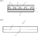
- the heating element 4 consists in a known manner of a web-shaped substrate 7 (preferably made of plastic), a heat distribution layer 8 made of a metallic material, electrodes 9, and a heating layer 10 made of PTC resistance elements, for example carbon pastes or ceramic layers, which are used as ohmic Resistance work.
- the electrodes 9 can for example be made of a hardened, silver-based paste that is applied in viscous form to the substrate 7 by means of screen printing with the desired course and is thermally hardened.
- the PTC resistance elements of the heating layer 10 can be made from a hardened, carbon-based paste, which is also referred to as carbon paste and which can also be applied in viscous form at room temperature by screen printing in the desired arrangement to the substrate 7 and thermally cured.
- the heating element 4 can be insulated from the outside by a dielectric cover film 11.
- the electrical resistance of the PTC resistance elements also changes based on a characteristic curve which, for example, shows a marked increase in a PTC lacquer at around 130 ° C. This marked increase in the characteristic curve means that there is no further heating above 130 ° C.
- the heating element 4 used is therefore self-regulating and cannot overheat.
- the PTC resistance elements enable particularly rapid heating compared to conventional resistance materials. After an initial warming-up phase, the area-related heating power averaged over the entire surface of the heating element 4 is approximately 100 kW / m 2 .
- the core temperature of the heating element 4 occurring in the heating layer 10 is a maximum of 120 ° C.
- Fig. 6 it is explained how the web-shaped heating element 4 designed as a heating film is folded around its longitudinal axis L and around its transverse axis Q to form the wall.
- the heat distribution layer 8 which is arranged on one side, is now on the outside on both sides of the heating element 4 and faces the respective flow channel section 1a, 1b.
- the surface of a first side of the folded, sheet-shaped heating element 4 always faces the outwardly winding flow channel section 1a, and the surface of the second side of the folded, sheet-shaped heating element 4 always faces the inwardly winding flow channel section 1b.
- the web-shaped substrate 7 forms a separating layer between the electrically conductive layers in the form of the electrodes 9 and the heating layer 10 and the fluid, which reduces the risk of short circuits.
- the front sides come to lie along the two broad sides of the heating film on the same side, which can now be arranged outside the housing 2. There is thus no cut edges of the heating foil that would be exposed to the fluid, so that a short circuit is again prevented.
- a device for heating a fluid by means of electrical energy is thus realized, which has a compact design and not only enables the fluid to be heated quickly, but can also be operated with a higher efficiency compared to known devices. Furthermore, a high level of operational reliability can be guaranteed.
Landscapes
- Engineering & Computer Science (AREA)
- Physics & Mathematics (AREA)
- Thermal Sciences (AREA)
- Chemical & Material Sciences (AREA)
- Combustion & Propulsion (AREA)
- Mechanical Engineering (AREA)
- General Engineering & Computer Science (AREA)
- Resistance Heating (AREA)
- Instantaneous Water Boilers, Portable Hot-Water Supply Apparatuses, And Control Of Portable Hot-Water Supply Apparatuses (AREA)
Applications Claiming Priority (1)
| Application Number | Priority Date | Filing Date | Title |
|---|---|---|---|
| AT601042019A AT522500B1 (de) | 2019-04-23 | 2019-04-23 | Spiralwärmetauscher |
Publications (3)
| Publication Number | Publication Date |
|---|---|
| EP3731596A2 true EP3731596A2 (fr) | 2020-10-28 |
| EP3731596A3 EP3731596A3 (fr) | 2020-11-04 |
| EP3731596B1 EP3731596B1 (fr) | 2021-06-16 |
Family
ID=70292842
Family Applications (1)
| Application Number | Title | Priority Date | Filing Date |
|---|---|---|---|
| EP20169807.3A Active EP3731596B1 (fr) | 2019-04-23 | 2020-04-16 | Échangeur de chaleur spirale |
Country Status (3)
| Country | Link |
|---|---|
| EP (1) | EP3731596B1 (fr) |
| AT (1) | AT522500B1 (fr) |
| ES (1) | ES2886339T3 (fr) |
Cited By (3)
| Publication number | Priority date | Publication date | Assignee | Title |
|---|---|---|---|---|
| WO2022211875A1 (fr) | 2021-03-29 | 2022-10-06 | Micropyretics Heaters International, Inc. | Élément chauffant configuré en double spirale inversée efficace en énergie et dispositif de chauffage à gaz l'utilisant |
| EP4418817A1 (fr) | 2023-02-17 | 2024-08-21 | Röchling Automotive SE | Dispositif d'espacement pour produire des éléments chauffants enroulés et élément chauffant enroulé |
| DE102024203750A1 (de) * | 2024-04-23 | 2025-11-06 | Volkswagen Aktiengesellschaft | Heizvorrichtung zum Erwärmen eines Kühlmittels |
Citations (5)
| Publication number | Priority date | Publication date | Assignee | Title |
|---|---|---|---|---|
| CH101971A (de) | 1923-06-06 | 1923-11-01 | Jost Emil | Elektrischer Heizapparat für Flüssigkeiten. |
| EP0104673A2 (fr) | 1982-09-24 | 1984-04-04 | Onofrio Rocchitelli | Dispositif de chauffage de liquide de lavage de vitres de véhicules automobiles et analogues |
| DE29618194U1 (de) | 1996-08-29 | 1996-12-12 | GEA Canzler GmbH, 52351 Düren | Spiralwärmetauscher |
| DE19837923C1 (de) | 1998-08-20 | 2000-01-20 | Hans Biermaier | Vorrichtung zum thermischen Sterilisieren von Flüssigkeiten |
| KR100762010B1 (ko) | 2006-07-07 | 2007-09-28 | 윤국선 | 유도가열 방식의 온열매트 |
Family Cites Families (6)
| Publication number | Priority date | Publication date | Assignee | Title |
|---|---|---|---|---|
| US5326537A (en) * | 1993-01-29 | 1994-07-05 | Cleary James M | Counterflow catalytic device |
| AU3784399A (en) * | 1998-05-05 | 1999-11-23 | Thermatrix Inc. | A device for thermally processing a gas stream, and method for same |
| JP3889698B2 (ja) * | 2002-11-22 | 2007-03-07 | 本田技研工業株式会社 | 蓄熱装置 |
| DE102009021656A1 (de) * | 2009-05-16 | 2010-11-18 | Wmf Württembergische Metallwarenfabrik Ag | Durchlauferhitzer und Verfahren zur Steuerung und Regelung eines solchen |
| WO2011072453A1 (fr) * | 2009-12-18 | 2011-06-23 | Advanced Materials Enterprises Company Limited | Appareil de chauffage d'eau |
| KR20130107764A (ko) * | 2012-03-23 | 2013-10-02 | 홍성훈 | 전기 순간 온수 가열관로 |
-
2019
- 2019-04-23 AT AT601042019A patent/AT522500B1/de not_active IP Right Cessation
-
2020
- 2020-04-16 EP EP20169807.3A patent/EP3731596B1/fr active Active
- 2020-04-16 ES ES20169807T patent/ES2886339T3/es active Active
Patent Citations (5)
| Publication number | Priority date | Publication date | Assignee | Title |
|---|---|---|---|---|
| CH101971A (de) | 1923-06-06 | 1923-11-01 | Jost Emil | Elektrischer Heizapparat für Flüssigkeiten. |
| EP0104673A2 (fr) | 1982-09-24 | 1984-04-04 | Onofrio Rocchitelli | Dispositif de chauffage de liquide de lavage de vitres de véhicules automobiles et analogues |
| DE29618194U1 (de) | 1996-08-29 | 1996-12-12 | GEA Canzler GmbH, 52351 Düren | Spiralwärmetauscher |
| DE19837923C1 (de) | 1998-08-20 | 2000-01-20 | Hans Biermaier | Vorrichtung zum thermischen Sterilisieren von Flüssigkeiten |
| KR100762010B1 (ko) | 2006-07-07 | 2007-09-28 | 윤국선 | 유도가열 방식의 온열매트 |
Cited By (4)
| Publication number | Priority date | Publication date | Assignee | Title |
|---|---|---|---|---|
| WO2022211875A1 (fr) | 2021-03-29 | 2022-10-06 | Micropyretics Heaters International, Inc. | Élément chauffant configuré en double spirale inversée efficace en énergie et dispositif de chauffage à gaz l'utilisant |
| EP4298864A4 (fr) * | 2021-03-29 | 2025-01-29 | Micropyretics Heaters International, Inc. | Élément chauffant configuré en double spirale inversée efficace en énergie et dispositif de chauffage à gaz l'utilisant |
| EP4418817A1 (fr) | 2023-02-17 | 2024-08-21 | Röchling Automotive SE | Dispositif d'espacement pour produire des éléments chauffants enroulés et élément chauffant enroulé |
| DE102024203750A1 (de) * | 2024-04-23 | 2025-11-06 | Volkswagen Aktiengesellschaft | Heizvorrichtung zum Erwärmen eines Kühlmittels |
Also Published As
| Publication number | Publication date |
|---|---|
| EP3731596A3 (fr) | 2020-11-04 |
| AT522500A1 (de) | 2020-11-15 |
| EP3731596B1 (fr) | 2021-06-16 |
| ES2886339T3 (es) | 2021-12-17 |
| AT522500B1 (de) | 2020-12-15 |
Similar Documents
| Publication | Publication Date | Title |
|---|---|---|
| EP0350528B1 (fr) | Radiateur | |
| EP4032369A1 (fr) | Carte de circuit imprimé et dispositif de chauffage de fluide | |
| EP3731596B1 (fr) | Échangeur de chaleur spirale | |
| DE3750959T2 (de) | Dieselbrennstofferwärmer. | |
| EP1657963A1 (fr) | Elément chauffant d'une carte de circuit imprimé, carte de circuit imprimé et procédé de chauffage | |
| EP2689946B1 (fr) | Dispositif de chauffage | |
| DE102017218899A1 (de) | Elektrische Heizvorrichtung für ein Kraftfahrzeug | |
| EP3016114B1 (fr) | Resistance electrique refroidie | |
| EP3417227B1 (fr) | Échangeur de chaleur, en particulier échangeur de chaleur eau-air ou échangeur de chaleur huile-eau | |
| WO2008071348A1 (fr) | Dispositif de chauffage ou de chauffage auxiliaire électrique, en particulier pour un système de chauffage ou de climatisation de véhicule à moteur | |
| EP2821729A1 (fr) | Échangeur thermique et dispositif de chauffage | |
| EP3646665B1 (fr) | Circuit pour commuter une resistance | |
| EP3417210A1 (fr) | Échangeur de chaleur huile-eau, en particulier pour moteur à combustion interne d'un véhicule automobile | |
| EP3494294B1 (fr) | Corps alvéolaire pouvant être chauffé électriquement pour le traitement des gaz d'échappement comportant une pluralité d'éléments chauffants | |
| WO2008071349A1 (fr) | Dispositif de chauffage ou de chauffage auxiliaire électrique, en particulier pour un système de chauffage ou de climatisation de véhicule à moteur | |
| EP1497594B1 (fr) | Dispositif de transmission de chaleur utilise a des fins de chauffage et comprenant un systeme electrique chauffant | |
| EP1839920A1 (fr) | Chauffage électrique pour un système de climatisation d'un véhicule | |
| EP3459110B1 (fr) | Unité de boîte de refroidissement et système électronique de puissance doté d'une unité de boîte de refroidissement | |
| EP3011803B1 (fr) | Dispositif de chauffage | |
| EP3953646B1 (fr) | Appareil de chauffage électrique | |
| EP3511645B1 (fr) | Dispositif de chauffage électrique | |
| DE102018205280A1 (de) | Kaltleitermodul | |
| DE4029513A1 (de) | Medienerhitzer fuer fluessigkeitsbetriebene heizkoerper | |
| DE102023208195A1 (de) | Elektrische Flüssigkeitsheizung für ein Fahrzeug | |
| EP3011802A1 (fr) | Dispositif de chauffage |
Legal Events
| Date | Code | Title | Description |
|---|---|---|---|
| PUAI | Public reference made under article 153(3) epc to a published international application that has entered the european phase |
Free format text: ORIGINAL CODE: 0009012 |
|
| STAA | Information on the status of an ep patent application or granted ep patent |
Free format text: STATUS: THE APPLICATION HAS BEEN PUBLISHED |
|
| PUAL | Search report despatched |
Free format text: ORIGINAL CODE: 0009013 |
|
| AK | Designated contracting states |
Kind code of ref document: A2 Designated state(s): AL AT BE BG CH CY CZ DE DK EE ES FI FR GB GR HR HU IE IS IT LI LT LU LV MC MK MT NL NO PL PT RO RS SE SI SK SM TR |
|
| AX | Request for extension of the european patent |
Extension state: BA ME |
|
| AK | Designated contracting states |
Kind code of ref document: A3 Designated state(s): AL AT BE BG CH CY CZ DE DK EE ES FI FR GB GR HR HU IE IS IT LI LT LU LV MC MK MT NL NO PL PT RO RS SE SI SK SM TR |
|
| AX | Request for extension of the european patent |
Extension state: BA ME |
|
| RIC1 | Information provided on ipc code assigned before grant |
Ipc: F28D 9/04 20060101ALI20200928BHEP Ipc: H05B 3/56 20060101AFI20200928BHEP Ipc: H05B 3/36 20060101ALI20200928BHEP Ipc: H05B 3/18 20060101ALI20200928BHEP Ipc: F24H 1/10 20060101ALI20200928BHEP |
|
| STAA | Information on the status of an ep patent application or granted ep patent |
Free format text: STATUS: REQUEST FOR EXAMINATION WAS MADE |
|
| 17P | Request for examination filed |
Effective date: 20201202 |
|
| RBV | Designated contracting states (corrected) |
Designated state(s): AL AT BE BG CH CY CZ DE DK EE ES FI FR GB GR HR HU IE IS IT LI LT LU LV MC MK MT NL NO PL PT RO RS SE SI SK SM TR |
|
| GRAP | Despatch of communication of intention to grant a patent |
Free format text: ORIGINAL CODE: EPIDOSNIGR1 |
|
| STAA | Information on the status of an ep patent application or granted ep patent |
Free format text: STATUS: GRANT OF PATENT IS INTENDED |
|
| RIC1 | Information provided on ipc code assigned before grant |
Ipc: H05B 3/56 20060101AFI20201221BHEP Ipc: F28D 9/04 20060101ALI20201221BHEP Ipc: H05B 3/36 20060101ALI20201221BHEP Ipc: F24H 1/10 20060101ALI20201221BHEP Ipc: H05B 3/18 20060101ALI20201221BHEP |
|
| INTG | Intention to grant announced |
Effective date: 20210122 |
|
| GRAS | Grant fee paid |
Free format text: ORIGINAL CODE: EPIDOSNIGR3 |
|
| GRAA | (expected) grant |
Free format text: ORIGINAL CODE: 0009210 |
|
| STAA | Information on the status of an ep patent application or granted ep patent |
Free format text: STATUS: THE PATENT HAS BEEN GRANTED |
|
| AK | Designated contracting states |
Kind code of ref document: B1 Designated state(s): AL AT BE BG CH CY CZ DE DK EE ES FI FR GB GR HR HU IE IS IT LI LT LU LV MC MK MT NL NO PL PT RO RS SE SI SK SM TR |
|
| REG | Reference to a national code |
Ref country code: GB Ref legal event code: FG4D Free format text: NOT ENGLISH |
|
| REG | Reference to a national code |
Ref country code: CH Ref legal event code: EP |
|
| REG | Reference to a national code |
Ref country code: DE Ref legal event code: R096 Ref document number: 502020000057 Country of ref document: DE |
|
| REG | Reference to a national code |
Ref country code: AT Ref legal event code: REF Ref document number: 1403414 Country of ref document: AT Kind code of ref document: T Effective date: 20210715 |
|
| REG | Reference to a national code |
Ref country code: IE Ref legal event code: FG4D Free format text: LANGUAGE OF EP DOCUMENT: GERMAN |
|
| REG | Reference to a national code |
Ref country code: SE Ref legal event code: TRGR |
|
| REG | Reference to a national code |
Ref country code: LT Ref legal event code: MG9D |
|
| PG25 | Lapsed in a contracting state [announced via postgrant information from national office to epo] |
Ref country code: LT Free format text: LAPSE BECAUSE OF FAILURE TO SUBMIT A TRANSLATION OF THE DESCRIPTION OR TO PAY THE FEE WITHIN THE PRESCRIBED TIME-LIMIT Effective date: 20210616 Ref country code: HR Free format text: LAPSE BECAUSE OF FAILURE TO SUBMIT A TRANSLATION OF THE DESCRIPTION OR TO PAY THE FEE WITHIN THE PRESCRIBED TIME-LIMIT Effective date: 20210616 Ref country code: FI Free format text: LAPSE BECAUSE OF FAILURE TO SUBMIT A TRANSLATION OF THE DESCRIPTION OR TO PAY THE FEE WITHIN THE PRESCRIBED TIME-LIMIT Effective date: 20210616 Ref country code: BG Free format text: LAPSE BECAUSE OF FAILURE TO SUBMIT A TRANSLATION OF THE DESCRIPTION OR TO PAY THE FEE WITHIN THE PRESCRIBED TIME-LIMIT Effective date: 20210916 |
|
| REG | Reference to a national code |
Ref country code: NL Ref legal event code: MP Effective date: 20210616 |
|
| PG25 | Lapsed in a contracting state [announced via postgrant information from national office to epo] |
Ref country code: GR Free format text: LAPSE BECAUSE OF FAILURE TO SUBMIT A TRANSLATION OF THE DESCRIPTION OR TO PAY THE FEE WITHIN THE PRESCRIBED TIME-LIMIT Effective date: 20210917 Ref country code: LV Free format text: LAPSE BECAUSE OF FAILURE TO SUBMIT A TRANSLATION OF THE DESCRIPTION OR TO PAY THE FEE WITHIN THE PRESCRIBED TIME-LIMIT Effective date: 20210616 Ref country code: NO Free format text: LAPSE BECAUSE OF FAILURE TO SUBMIT A TRANSLATION OF THE DESCRIPTION OR TO PAY THE FEE WITHIN THE PRESCRIBED TIME-LIMIT Effective date: 20210916 Ref country code: RS Free format text: LAPSE BECAUSE OF FAILURE TO SUBMIT A TRANSLATION OF THE DESCRIPTION OR TO PAY THE FEE WITHIN THE PRESCRIBED TIME-LIMIT Effective date: 20210616 |
|
| REG | Reference to a national code |
Ref country code: ES Ref legal event code: FG2A Ref document number: 2886339 Country of ref document: ES Kind code of ref document: T3 Effective date: 20211217 |
|
| PG25 | Lapsed in a contracting state [announced via postgrant information from national office to epo] |
Ref country code: EE Free format text: LAPSE BECAUSE OF FAILURE TO SUBMIT A TRANSLATION OF THE DESCRIPTION OR TO PAY THE FEE WITHIN THE PRESCRIBED TIME-LIMIT Effective date: 20210616 Ref country code: SK Free format text: LAPSE BECAUSE OF FAILURE TO SUBMIT A TRANSLATION OF THE DESCRIPTION OR TO PAY THE FEE WITHIN THE PRESCRIBED TIME-LIMIT Effective date: 20210616 Ref country code: RO Free format text: LAPSE BECAUSE OF FAILURE TO SUBMIT A TRANSLATION OF THE DESCRIPTION OR TO PAY THE FEE WITHIN THE PRESCRIBED TIME-LIMIT Effective date: 20210616 Ref country code: NL Free format text: LAPSE BECAUSE OF FAILURE TO SUBMIT A TRANSLATION OF THE DESCRIPTION OR TO PAY THE FEE WITHIN THE PRESCRIBED TIME-LIMIT Effective date: 20210616 Ref country code: PT Free format text: LAPSE BECAUSE OF FAILURE TO SUBMIT A TRANSLATION OF THE DESCRIPTION OR TO PAY THE FEE WITHIN THE PRESCRIBED TIME-LIMIT Effective date: 20211018 Ref country code: SM Free format text: LAPSE BECAUSE OF FAILURE TO SUBMIT A TRANSLATION OF THE DESCRIPTION OR TO PAY THE FEE WITHIN THE PRESCRIBED TIME-LIMIT Effective date: 20210616 Ref country code: CZ Free format text: LAPSE BECAUSE OF FAILURE TO SUBMIT A TRANSLATION OF THE DESCRIPTION OR TO PAY THE FEE WITHIN THE PRESCRIBED TIME-LIMIT Effective date: 20210616 |
|
| PG25 | Lapsed in a contracting state [announced via postgrant information from national office to epo] |
Ref country code: PL Free format text: LAPSE BECAUSE OF FAILURE TO SUBMIT A TRANSLATION OF THE DESCRIPTION OR TO PAY THE FEE WITHIN THE PRESCRIBED TIME-LIMIT Effective date: 20210616 |
|
| REG | Reference to a national code |
Ref country code: DE Ref legal event code: R097 Ref document number: 502020000057 Country of ref document: DE |
|
| PLBE | No opposition filed within time limit |
Free format text: ORIGINAL CODE: 0009261 |
|
| STAA | Information on the status of an ep patent application or granted ep patent |
Free format text: STATUS: NO OPPOSITION FILED WITHIN TIME LIMIT |
|
| PG25 | Lapsed in a contracting state [announced via postgrant information from national office to epo] |
Ref country code: DK Free format text: LAPSE BECAUSE OF FAILURE TO SUBMIT A TRANSLATION OF THE DESCRIPTION OR TO PAY THE FEE WITHIN THE PRESCRIBED TIME-LIMIT Effective date: 20210616 |
|
| 26N | No opposition filed |
Effective date: 20220317 |
|
| PG25 | Lapsed in a contracting state [announced via postgrant information from national office to epo] |
Ref country code: AL Free format text: LAPSE BECAUSE OF FAILURE TO SUBMIT A TRANSLATION OF THE DESCRIPTION OR TO PAY THE FEE WITHIN THE PRESCRIBED TIME-LIMIT Effective date: 20210616 |
|
| REG | Reference to a national code |
Ref country code: BE Ref legal event code: MM Effective date: 20220430 |
|
| PG25 | Lapsed in a contracting state [announced via postgrant information from national office to epo] |
Ref country code: MC Free format text: LAPSE BECAUSE OF FAILURE TO SUBMIT A TRANSLATION OF THE DESCRIPTION OR TO PAY THE FEE WITHIN THE PRESCRIBED TIME-LIMIT Effective date: 20210616 Ref country code: LU Free format text: LAPSE BECAUSE OF NON-PAYMENT OF DUE FEES Effective date: 20220416 |
|
| PG25 | Lapsed in a contracting state [announced via postgrant information from national office to epo] |
Ref country code: BE Free format text: LAPSE BECAUSE OF NON-PAYMENT OF DUE FEES Effective date: 20220430 |
|
| PG25 | Lapsed in a contracting state [announced via postgrant information from national office to epo] |
Ref country code: IE Free format text: LAPSE BECAUSE OF NON-PAYMENT OF DUE FEES Effective date: 20220416 |
|
| REG | Reference to a national code |
Ref country code: CH Ref legal event code: PL |
|
| PG25 | Lapsed in a contracting state [announced via postgrant information from national office to epo] |
Ref country code: LI Free format text: LAPSE BECAUSE OF NON-PAYMENT OF DUE FEES Effective date: 20230430 Ref country code: CH Free format text: LAPSE BECAUSE OF NON-PAYMENT OF DUE FEES Effective date: 20230430 |
|
| PG25 | Lapsed in a contracting state [announced via postgrant information from national office to epo] |
Ref country code: MK Free format text: LAPSE BECAUSE OF FAILURE TO SUBMIT A TRANSLATION OF THE DESCRIPTION OR TO PAY THE FEE WITHIN THE PRESCRIBED TIME-LIMIT Effective date: 20210616 Ref country code: CY Free format text: LAPSE BECAUSE OF FAILURE TO SUBMIT A TRANSLATION OF THE DESCRIPTION OR TO PAY THE FEE WITHIN THE PRESCRIBED TIME-LIMIT Effective date: 20210616 |
|
| REG | Reference to a national code |
Ref country code: DE Ref legal event code: R082 Ref document number: 502020000057 Country of ref document: DE Representative=s name: NEUHOLD, ALFRED, DR.TECHN., CH Ref country code: DE Ref legal event code: R082 Ref document number: 502020000057 Country of ref document: DE Representative=s name: IPRIME KUENSCH PATENTANWAELTE GMBH, LI |
|
| PG25 | Lapsed in a contracting state [announced via postgrant information from national office to epo] |
Ref country code: HU Free format text: LAPSE BECAUSE OF FAILURE TO SUBMIT A TRANSLATION OF THE DESCRIPTION OR TO PAY THE FEE WITHIN THE PRESCRIBED TIME-LIMIT; INVALID AB INITIO Effective date: 20200416 |
|
| PGFP | Annual fee paid to national office [announced via postgrant information from national office to epo] |
Ref country code: SE Payment date: 20240328 Year of fee payment: 5 Ref country code: IT Payment date: 20240326 Year of fee payment: 5 Ref country code: FR Payment date: 20240327 Year of fee payment: 5 |
|
| PG25 | Lapsed in a contracting state [announced via postgrant information from national office to epo] |
Ref country code: TR Free format text: LAPSE BECAUSE OF FAILURE TO SUBMIT A TRANSLATION OF THE DESCRIPTION OR TO PAY THE FEE WITHIN THE PRESCRIBED TIME-LIMIT Effective date: 20210616 |
|
| PGFP | Annual fee paid to national office [announced via postgrant information from national office to epo] |
Ref country code: GB Payment date: 20240424 Year of fee payment: 5 |
|
| PGFP | Annual fee paid to national office [announced via postgrant information from national office to epo] |
Ref country code: ES Payment date: 20240503 Year of fee payment: 5 |
|
| PG25 | Lapsed in a contracting state [announced via postgrant information from national office to epo] |
Ref country code: MT Free format text: LAPSE BECAUSE OF FAILURE TO SUBMIT A TRANSLATION OF THE DESCRIPTION OR TO PAY THE FEE WITHIN THE PRESCRIBED TIME-LIMIT Effective date: 20210616 |
|
| REG | Reference to a national code |
Ref country code: DE Ref legal event code: R082 Ref document number: 502020000057 Country of ref document: DE Representative=s name: NEUHOLD, ALFRED, DR.TECHN., CH |
|
| PGFP | Annual fee paid to national office [announced via postgrant information from national office to epo] |
Ref country code: DE Payment date: 20250422 Year of fee payment: 6 |
|
| PGFP | Annual fee paid to national office [announced via postgrant information from national office to epo] |
Ref country code: AT Payment date: 20250721 Year of fee payment: 5 |
|
| REG | Reference to a national code |
Ref country code: SE Ref legal event code: EUG |
|
| GBPC | Gb: european patent ceased through non-payment of renewal fee |
Effective date: 20250416 |
|
| PG25 | Lapsed in a contracting state [announced via postgrant information from national office to epo] |
Ref country code: GB Free format text: LAPSE BECAUSE OF NON-PAYMENT OF DUE FEES Effective date: 20250416 |
|
| PG25 | Lapsed in a contracting state [announced via postgrant information from national office to epo] |
Ref country code: FR Free format text: LAPSE BECAUSE OF NON-PAYMENT OF DUE FEES Effective date: 20250430 |
|
| PG25 | Lapsed in a contracting state [announced via postgrant information from national office to epo] |
Ref country code: SE Free format text: LAPSE BECAUSE OF NON-PAYMENT OF DUE FEES Effective date: 20250417 |
|
| PG25 | Lapsed in a contracting state [announced via postgrant information from national office to epo] |
Ref country code: IT Free format text: LAPSE BECAUSE OF NON-PAYMENT OF DUE FEES Effective date: 20250416 |