EP3732329B1 - Procédé servant à faire fonctionner un groupe de bourrage de traverses d'un engin de pose de voie, ainsi que dispositif de ballastage servant au compactage de ballast, et engin de pose de voie - Google Patents
Procédé servant à faire fonctionner un groupe de bourrage de traverses d'un engin de pose de voie, ainsi que dispositif de ballastage servant au compactage de ballast, et engin de pose de voie Download PDFInfo
- Publication number
- EP3732329B1 EP3732329B1 EP18811768.3A EP18811768A EP3732329B1 EP 3732329 B1 EP3732329 B1 EP 3732329B1 EP 18811768 A EP18811768 A EP 18811768A EP 3732329 B1 EP3732329 B1 EP 3732329B1
- Authority
- EP
- European Patent Office
- Prior art keywords
- tamping
- unit
- tamping unit
- damage
- track
- Prior art date
- Legal status (The legal status is an assumption and is not a legal conclusion. Google has not performed a legal analysis and makes no representation as to the accuracy of the status listed.)
- Active
Links
Images




Classifications
-
- E—FIXED CONSTRUCTIONS
- E01—CONSTRUCTION OF ROADS, RAILWAYS, OR BRIDGES
- E01B—PERMANENT WAY; PERMANENT-WAY TOOLS; MACHINES FOR MAKING RAILWAYS OF ALL KINDS
- E01B27/00—Placing, renewing, working, cleaning, or taking-up the ballast, with or without concurrent work on the track; Devices therefor; Packing sleepers
- E01B27/12—Packing sleepers, with or without concurrent work on the track; Compacting track-carrying ballast
- E01B27/13—Packing sleepers, with or without concurrent work on the track
- E01B27/16—Sleeper-tamping machines
-
- E—FIXED CONSTRUCTIONS
- E01—CONSTRUCTION OF ROADS, RAILWAYS, OR BRIDGES
- E01B—PERMANENT WAY; PERMANENT-WAY TOOLS; MACHINES FOR MAKING RAILWAYS OF ALL KINDS
- E01B35/00—Applications of measuring apparatus or devices for track-building purposes
-
- E—FIXED CONSTRUCTIONS
- E01—CONSTRUCTION OF ROADS, RAILWAYS, OR BRIDGES
- E01B—PERMANENT WAY; PERMANENT-WAY TOOLS; MACHINES FOR MAKING RAILWAYS OF ALL KINDS
- E01B2203/00—Devices for working the railway-superstructure
- E01B2203/12—Tamping devices
Definitions
- the invention relates to a method for operating a tamping unit of a track construction machine and further to a tamping device for track bed compaction and a track construction machine.
- Rail-guided track construction machines are used to maintain a track bed.
- Such track construction machines have a tamping unit that can be moved in a vertical direction for track bed compaction, with a unit frame and at least two tamping tines that can be moved relative to the unit frame.
- the tamping unit is repeatedly moved in a vertical direction between a reset position in which the tamping unit is disengaged from the track bed and an engagement position in which the tamping unit is engaged with the track bed.
- the at least two tamping tines are moved cyclically relative to the unit frame. This places a great deal of stress on the tamping unit, which can lead to damage to the tamping unit, in particular to a tamping tine breaking.
- the track bed is not compacted sufficiently and functional components of the tamping unit can be overstressed.
- time-consuming and costly inspection and maintenance work is carried out regularly.
- Tamping units and methods for track bed treatment are known, for example, from GB 2,451,310 A , from the EP 2 770 108 A1 , from the EP 3 239 398 A1 , from the WO 2014/102401 A1 , from the WO 2017/097390 A1 and from the WO 2017/129215 A1 .
- the invention is based on the object of creating a method for operating a tamping unit of a track construction machine, which increases the reliability and economic efficiency of the tamping unit during operation.
- a state of damage to a tamping pick of the tamping unit designed to interact with the track bed can be determined using the at least one measured variable.
- the at least one part of the tamping unit can be understood to mean a component or part of a component of the tamping unit.
- the tamping unit can comprise an unit frame, at least two tamping pick supports attached to the unit frame and displaceable relative to it, and a tamping pick drive for displacing the at least two tamping pick supports relative to the unit frame.
- the tamping pick can be attached to one of the at least two tamping pick supports.
- the at least two tamping picks are subjected to particularly high stress when the tamping unit is in operation.
- the at least two tamping picks are therefore subjected to high levels of wear, which means that breakage of the at least two tamping picks cannot be ruled out. If one of the at least two tamping tines breaks, the track bed is only partially compacted and therefore inadequate.
- By quickly and reliably identifying the damage to the at least two tamping tines they can be replaced as soon as the damage occurs.
- the damage to the tamping unit, in particular the tamping tine can thus be identified particularly reliably and promptly after the damage occurs, in particular automatically.
- the tamping unit can be displaced in a vertical direction by means of a unit drive.
- the tamping unit can be accelerated as a whole, in particular by means of the unit drive.
- the acceleration of at least one part of the tamping unit can also be achieved by accelerating at least one of the components, in particular the unit frame and/or the at least two tamping tine supports and/or the at least two tamping tines and/or the tamping tine drive or a part of this at least one component.
- Acceleration can be achieved by means of the drive device and/or by means of a separate exciter drive and/or by means of an exciter brake.
- the drive device can comprise the unit drive and the tamping tine drive.
- the exciter drive can be positioned anywhere on the tamping unit and operated independently of the track bed compaction. A movement of at least part of the tamping unit can be braked by means of the exciter brake.
- the acceleration can be discrete and/or cyclical. During acceleration, a movement speed of at least one part can be increased and/or reduced.
- a driving force required for acceleration and/or an acceleration can be recorded.
- the driving force is also understood to mean a braking force required for negative acceleration and for deceleration.
- the at least one measured variable can be recorded on the at least one part of the tamping unit.
- the at least one measured variable can also be recorded on a part of the at least one part spaced position.
- the at least one measured variable can also be a variable that correlates with the driving force, in particular a hydraulic pressure in a hydraulic cylinder and/or a current flow in an electric motor.
- the at least one measured variable can also be a measured variable that correlates with the acceleration, in particular a speed and/or an angular velocity.
- the at least one measured variable can be recorded continuously over time or at discrete points in time.
- the damage state can be determined analogously or digitally.
- the at least one measured variable is recorded at at least two, in particular at least three, in particular at least four, measuring positions on the tamping unit.
- the damage status of the tamping unit can be determined by distinguishing between functionality and damage to the tamping unit.
- a functional tamping unit is understood to be an undamaged tamping unit.
- the damage status can also be determined by determining the type and/or position and/or severity of the damage. For example, the damage status can be determined for at least one of the components of the tamping unit. The advantage of this is that damaged components of the tamping unit can be identified and replaced quickly and reliably.
- a change in at least one measured variable can be determined.
- the speed of the change in at least one measured variable can also be used to determine the state of damage of the tamping unit. Wear of the tamping unit that increases over time can thus be distinguished from a sudden failure of the tamping unit, in particular of a component of the tamping unit.
- a method according to claim 2 ensures the increased reliability and efficiency of the track construction machine.
- Damage to one of the at least two tamping tines can, for example, lead to a change in a Bearing play and/or a change in the mass of the tamping tine.
- the at least one measured variable correlating with the acceleration changes along with the damage to the tamping tine. Damage to the tamping unit, in particular to one of the at least two tamping tines, can thus be detected particularly reliably by accelerating the at least two tamping tines.
- the at least two tamping tines can be accelerated by means of the drive device, in particular relative to the unit frame.
- the tamping tines are preferably accelerated via the tamping tine drive.
- the at least one measured variable can be recorded directly on the at least two tamping tines.
- the at least one measured variable can also be recorded on the at least two tamping tine supports and/or on the drive device, in particular on the tamping tine drive, in particular on a drive housing of the tamping tine drive, and/or on the unit frame.
- the drive housing can at least partially enclose a gear of the tamping tine drive and is also referred to as a gear box.
- a method according to claim 3 ensures the increased reliability and cost-effectiveness of the track construction machine.
- the position and/or the orientation of the tamping unit in particular of a component of the tamping unit, can be detected particularly easily and reliably.
- the position can be, for example, the vertical position of the tamping unit relative to the unit carrier.
- the orientation can be an angle of rotation of the tamping pick carrier.
- sensors of the drive device required to drive the tamping unit can be used to detect the at least one measured variable.
- the position and/or the orientation can be detected, for example, by means of a position sensor and/or a rotary encoder.
- a Hall sensor and/or a Potentiometer and/or a cable length sensor and/or an ultrasonic sensor and/or a laser sensor may be used.
- a method according to claim 4 ensures the increased reliability and cost-effectiveness of the track construction machine.
- the acceleration of at least one part takes place by means of the drive device.
- the measured variable that correlates with the acceleration can be reliably recorded directly on the drive device.
- the drive device acts on the at least two tamping tines via the at least two tamping tine supports. By recording the at least one measured variable on one of the at least two tamping tine supports, it is recorded along the load flow, between the drive device and the at least two tamping tines that are subject to particularly high loads. In particular, damage to the at least two tamping tines can thus be determined particularly reliably.
- the at least one measured variable can be an angular acceleration of the at least two tamping tine supports and/or a linear acceleration, in particular of the support bearing via which the at least one tamping tine support is connected to the tamping tine drive.
- the at least one measured variable can also be a travel of the drive device, in particular of the unit drive and/or the tamping tine drive. The at least one measured variable can thus be recorded particularly robustly and reliably.
- a method according to claim 5 ensures the reliability and cost-effectiveness of the track construction machine.
- the hydraulic pressure can be the pressure of a hydraulic fluid of the tamping tine drive and/or the unit drive.
- the hydraulic pressure can thus correlate with the drive force. Since the drive force correlates with the acceleration via the inertia of the tamping unit, the at least one measured variable can be determined particularly easily and robustly using the hydraulic pressure.
- a moment acting on the at least two tamping tines and/or a force acting on the at least two tamping tines can be determined.
- the at least one measured variable can also be in the form of the
- the damage status of the tamping unit can be determined based on a change in the force and/or the torque.
- a method according to claim 6 ensures the increased reliability and cost-effectiveness of the track construction machine.
- the tamping unit In the reset position, the tamping unit is not engaged with the track bed.
- influences of the track bed on the acceleration of at least one part of the tamping unit can be excluded.
- a varying condition of the track bed along the track has no influence on the at least one measured variable. The damage status of the tamping unit can thus be detected particularly robustly and reliably.
- the at least one reference variable can correspond to the at least one measured variable for a specific damage state.
- the at least one reference variable corresponds to the at least one measured variable for the functional state and/or for the damaged state of the tamping unit and/or for the damaged state of at least one component of the tamping unit.
- the at least one measured variable is compared with several reference variables.
- At least two reference variables can correspond to several specific damage states.
- it can be determined not only whether, but also to what extent, at which point and at which component damage to the tamping unit is present.
- the at least one reference variable is recorded by recording the at least one measured variable in a specific damage state.
- the at least one reference variable can also be determined once, in particular during installation and/or after maintenance of the tamping unit.
- the at least one reference variable can be determined regularly, in particular after a maximum of 100, in particular after a maximum of 10, in particular after each tamping cycle.
- a tamping cycle includes moving the tamping unit from the reset position to the engagement position and back to the reset position.
- the at least one reference variable is thus available for later comparison with the at least one measured variable. This also advantageously ensures that the at least one reference variable can be individually adapted to the respective tamping unit, in particular to the individual kinematic and mechanical properties of the tamping unit, and in particular to normal wear.
- a method according to claim 8 ensures the reliability and cost-effectiveness of the track construction machine.
- Damage to the tamping unit can be determined particularly easily and reliably if the at least one measured variable deviates from the at least one reference variable in the form of at least one previously recorded measured variable.
- the reference variable can also include several measured variables recorded at an earlier point in time. Several measured variables spaced apart in time can also be compared with the at least one reference variable to determine the state of damage. The determination of the state of damage is therefore particularly robust against random measurement deviations.
- the at least two tamping tines can be removed from the tamping unit before it is operated.
- the at least one measurement variable can be the position and/or orientation of the at least one part.
- the acceleration of the at least one part can be determined from the position and/or orientation.
- the recording of the at least one measured variable is particularly simple and robust.
- a change in the at least one measured variable over time can be recorded based on the time course. For example, it can be determined how much the tamping unit, in particular an individual component of the tamping unit, has already worn out and/or whether there is sudden damage to the tamping unit, in particular a break in one of the at least two tamping picks.
- an amplitude and/or a phase shift and/or a frequency of the at least one measured variable can be determined to determine the damage state.
- an amplitude of a linear acceleration and/or an angular acceleration can be determined to determine the damage state.
- a phase shift of a linear acceleration and/or an angular acceleration is determined to determine the damage state of the tamping unit.
- a method according to claim 10 ensures the increased reliability and cost-effectiveness of the track construction machine.
- the structural model preferably includes information about the geometric design and/or the bearing and/or the materials, in particular the density and/or the rigidity, of the tamping unit.
- the structural model and the at least one measured variable can be used to determine the state of damage particularly reliably and/or the extent of the damage can be determined.
- the structural model can be used to determine which component, in particular whether the at least two tamping picks and/or a bearing point and/or the drive device, is damaged and/or how severely it is damaged.
- the state of wear of the tamping unit can also be determined. The operability of the tamping unit can thus be exploited to the greatest extent possible, thereby increasing the economic efficiency of the track construction machine.
- a method according to claim 11 ensures the increased reliability and cost-effectiveness of the track construction machine.
- the damage to the tamping unit is preferably detected when the at least one measured variable exceeds the at least one threshold value.
- the at least one measured variable can be low when the tamping unit is in working order and increase when the tamping unit is damaged.
- the damage can be determined immediately, in particular without further comparison with other values.
- the threshold value can be fixed. The damage can thus be determined particularly easily and reliably.
- the at least one sensor for detecting the at least one measured variable can be attached to the tamping unit at a distance from a center of gravity of the tamping unit, for example.
- the at least one sensor can be designed as an acceleration sensor for detecting acceleration in the vertical direction. When the tamping unit is in working order, the acceleration acting on the at least one sensor is low. If the at least two tamping picks break, the acceleration of the at least one sensor in the vertical direction can increase significantly. If the at least one threshold value is exceeded, damage to the tamping unit can be detected.
- a difference between the measured value and the reference value can also be compared with a threshold value.
- a method according to claim 12 ensures the increased reliability and cost-effectiveness of the track construction machine. By interrupting the operation of the tamping unit after the damage has been detected, it can be prevented that the track bed is only insufficiently compacted and that the tamping unit is exposed to increased stress.
- a signal in particular a A warning tone and/or a visual signal are provided for a user. This has the advantage that the damage to the tamping unit is noticed by the user promptly after the damage occurs.
- a loss of mass of the tamping unit in particular in the dynamic system of the tamping unit, can be concluded. Based on the loss of mass, the state of damage of the tamping unit can be determined.
- a movement pattern of the tamping unit in particular of a part of the tamping unit, can be determined using the at least one measured variable.
- the damage state of the tamping unit can be determined based on a change in the movement pattern.
- the invention is further based on the object of creating a tamping device for track bed compaction which has increased reliability and economic efficiency in operation.
- a tamping device with the features of claim 13.
- the advantages of the tamping device according to the invention correspond to the advantages of the method according to the invention.
- the tamping device can be further developed in particular with the features of at least one of claims 1 to 12.
- the tamping unit is attached to the unit carrier so that it can be displaced in the vertical direction.
- the at least one sensor can be designed as an acceleration sensor and/or as a pressure sensor and/or as a position sensor and/or as a rotary encoder and/or as a current sensor.
- the at least one sensor is preferably in signal connection with the evaluation unit.
- the tamping device can have a control unit for controlling the drive device and/or for signaling a damage state of the tamping unit.
- the control unit can have a user interface for signaling the damage state.
- the control unit is preferably designed for this purpose. designed to interrupt the operation of the tamping device, in particular of the tamping unit, when damage is signaled by the evaluation unit.
- the control unit can also be designed to output a signal, in particular a signal tone and/or a visual signal, to the user via the user interface when the evaluation unit signals damage to the tamping unit.
- the invention is further based on the object of creating a track construction machine with a tamping device which has increased reliability and economic efficiency.
- a track construction machine 1 has a machine frame 2, at least two axles 3 mounted on the machine frame 2, a machine drive 4 and a tamping device 5 for track bed compaction.
- the axles 3 are arranged on the track construction machine 1 at a distance from one another along a horizontal x-direction.
- the x-direction together with a vertical z-direction and a horizontal y-direction, forms a machine-fixed coordinate system.
- Rail-guided wheels 6 are rotatably mounted on the axles 3.
- the machine drive 2 is designed to drive the wheels 6 of at least one of the axles 3 in rotation.
- the tamping device 5 has an aggregate carrier 7, a tamping aggregate 8 mounted on the aggregate carrier 7, a drive device 9, a sensor 10 and an evaluation unit 11.
- a linear guide 12 is arranged between the aggregate carrier 7 and the tamping aggregate 8.
- the tamping aggregate 8 can be displaced along the z-direction relative to the aggregate carrier 7 via the linear guide 12.
- the drive device 9 comprises an aggregate drive 13 and a tamping tine drive 14.
- the aggregate drive 13 acts between the aggregate carrier 7 and the tamping aggregate 8 and provides an aggregate force F A for displacing the tamping aggregate 8 relative to the aggregate carrier 7.
- the tamping aggregate 8 has an aggregate frame 15.
- Two tamping tine carriers 16 are attached to the aggregate frame 15 at a distance from one another in the x direction.
- the tamping tine carriers 16 are each rotatably mounted on the aggregate frame 15 via a carrier axis 17 oriented parallel to the y direction.
- the tamping tine drive 14 is designed as a linear drive and acts between the unit frame 15 and one of the tamping tine supports 16.
- the tamping tine drive 14 has a hydraulic drive and an eccentric drive.
- the hydraulic drive ensures a high displacement amplitude at a low displacement frequency.
- the eccentric drive is designed to provide a low displacement amplitude and a high displacement frequency, in particular a compaction frequency f V .
- Both the hydraulic drive and the eccentric drive act between the unit frame 15 and the respective Tamping tine carrier 16.
- the tamping tine drive 14 is designed to provide a driving force F V to the respective tamping tine carrier 16.
- Two tamping tines 18 are attached to an underside of the respective tamping tine carrier 16. The driving force F V can thus be transferred to a track bed 19 via the respective tamping tine carrier 16 and the tamping tines 18 attached to it.
- the sensor 10 is in signal connection with the evaluation unit 11 via a signal line 20.
- the evaluation unit 11 is in turn in signal connection with a control unit 21.
- the control unit 21 has a user interface 22 for exchanging information with a user.
- the evaluation unit 11 comprises a storage means 23 for storing at least one reference variable.
- the sensor 10 is designed as an acceleration sensor and is arranged on a drive housing 24 of the tamping pick drive 14.
- the track construction machine 1 To create or maintain the track bed 19, the track construction machine 1 is moved along the x-direction on a track 25 by means of the machine drive 4.
- a central axis 26 of the tamping device 5 is positioned centrally above a railway sleeper 27 arranged on the track bed 19 to support the tracks 25.
- the tamping unit 8 is in a reset position 28.
- the tamping unit 8 is located at an upper end position of the linear guide 12 and the tamping picks 18 attached to the tamping unit 8 are not engaged with the track bed 19.
- the tamping unit 8 is functional and shows no damage.
- the tamping tine drive 14 is activated by a signal from the control unit 21.
- the tamping tine drive 14 is connected to the two Tamping tine carriers 16.
- the tamping tine drive 14 transmits a cyclic lifting movement to the respective tamping tine carrier 16.
- the rotatably mounted tamping tine carriers 16 move cyclically about the respective carrier axis 17.
- the cyclical lifting movement transmitted from the tamping tine drive 14 to the two tamping tine supports 16 has a compression frequency f V of 35 Hertz to 45 Hertz.
- Bearing forces are transmitted to the unit frame 15 via the bearing axes 17 of the tamping tine supports 16 and via the drive housing 24 of the tamping tine drive 14 and excite the tamping unit 8 to oscillate at an unit frequency f A .
- the unit frequency f A essentially corresponds to the compression frequency f V .
- the unit frequency f A also acts on the drive housing 24 and causes it to oscillate.
- the sensor 10 attached to the drive housing 24 records six measured variables in the form of the vector of the linear accelerations a and the vector of the angular accelerations ⁇ .
- the accelerations a , ⁇ recorded by the sensor 10 are dependent on a mass m A of the tamping unit 8, in particular on masses m S of the respective tamping tines 18.
- the drive force F V in the return position 28 is only counteracted by the inertial force F T.
- M V is a drive torque
- I is an inertial moment
- M T is a moment of inertia acting due to the angular acceleration ⁇ and due to the inertial moment I.
- the aggregate amplitudes S a of the linear accelerations a and the aggregate amplitudes S a of the angular accelerations ⁇ are dependent on the mass m A of the tamping unit 8, in particular on the mass m S of the tamping pick 18.
- the courses of the measured variables a , ⁇ are determined for the undamaged tamping unit 8 and stored in the storage means 23 as reference variables a 0 , ⁇ 0 .
- the reference variables and the resulting further variables are marked with the index 0 below.
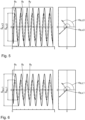
- the curves of the linear accelerations a 0 of the functional tamping unit 8 are shown over a time t.
- the tamping unit 8 is moved towards the track bed 19 by means of the unit drive 13 in the opposite direction to the z-direction.
- the tamping unit 8 In an engagement position 30, the tamping unit 8 is located at a lower end of the linear guide 12. The four tamping picks 18 penetrate into the track bed 19.
- the tamping unit 8 arranged in the engagement position 30 is in Fig. 3 and Fig. 4
- the operation of the tamping tine drive 14 is maintained during the displacement between the reset position 28 and the engagement position 30 as well as in the engagement position 30.
- the tamping tines 18 spaced apart in the x-direction are moved towards each other by means of the tamping tine drive 14 in the engagement position 30.
- the compaction of the track bed 19 takes place by the superposition of these two displacement components of the tamping tines 18.
- the tamping unit 8 is moved back from the engagement position 30 to the reset position 28 by means of the unit drive 13. The tamping cycle is thus completed.
- the Track construction machine 1 in particular the tamping device 5, is displaced in the x-direction such that the central axis 26 is arranged centrally above the next railway sleeper 27 in the x-direction.
- the breakage of the tamping pick 18 reduces its mass m S. This also reduces the mass of the tamping unit m A. This changes the inertia forces F T and moments of inertia M T that counteract the driving force F V. This in turn affects the vibration behavior of the tamping unit 8.
- the measured variables a , ⁇ are recorded again using the sensor 10.
- the measured variables a, ⁇ recorded using the damaged tamping unit 8 and the other variables resulting from them are identified below with the index 1.
- the current measured variables a 1 , ⁇ 1 are compared with the reference variables a 0 , ⁇ 0.
- the aggregate amplitudes S a,1 , S ⁇ ,1 and the phase shifts ⁇ a,1 , ⁇ ⁇ ,1 of the measured variables a 1 , ⁇ 1 are compared with the aggregate amplitudes S a,0 , S ⁇ ,0 and the phase shifts ⁇ a,0 , ⁇ ⁇ ,0 of the reference variables a 0 , ⁇ 0 .
- Damage to the tamping unit 8 is detected if a difference between the measured unit amplitudes S a,1 , S ⁇ ,1 and the reference values of the unit amplitudes S a,0 , S ⁇ ,0 reaches or exceeds a threshold value SW S.
- Damage to the tamping unit 8 is also detected if a difference between the measured phase shifts ⁇ a,1 , ⁇ ⁇ ,1 and the reference values of the phase shifts ⁇ a,0 , ⁇ ⁇ ,0 exceeds a threshold value SW ⁇ for the phase shifts. Damage to the tamping unit is therefore determined if the following applies: S 1 ⁇ S 0 ⁇ SW S ⁇ 1 ⁇ ⁇ 0 ⁇ SW ⁇
- Fig. 6 the curves of the linear accelerations a 1 recorded at the sensor 10 for the damaged tamping unit 8 with the broken tamping pick 18 are shown over time. From the Fig. 6 the aggregate amplitudes S a,1 and the phase shifts ⁇ a,1 of the linear accelerations emerge. In Fig. 8 are the courses of the Angular accelerations ⁇ 1 of the damaged tamping unit 8 are shown over time t. From the Fig. 8 the aggregate amplitudes S ⁇ ,1 and the phase shifts ⁇ ⁇ ,1 of the angular accelerations ⁇ 1 emerge.
- the evaluation unit 11 detects damage to the tamping unit 8. Based on a signal from the evaluation unit 11, the control unit 21 interrupts the operation of the tamping unit 8. The user is notified of the damage to the tamping unit 8 via the user interface 22.
- the tamping device 5 comprises two sensors 10, which are designed as position sensors.
- the two sensors 10 are each arranged on a tamping tine drive 14 and are designed to detect a travel s of the tamping tine drive 14.
- the sensors 10 are in signal connection with the evaluation unit 11 via a signal line 20.
- the measured variable s is recorded in the form of the travel s.
- the actuating acceleration s" d 2 s/dt 2 is determined.
- the setting acceleration s" is used in the same way as the accelerations a , ⁇ according to the previous embodiment.
- a position in the x-direction and/or in the y-direction and/or in the z-direction can also be recorded.
- An orientation around the x-direction and/or around the y-direction and/or the z-direction, for example from one of the tamping pick carriers 16, can be detected.
- FIG. 10 A further embodiment of the stuffing device 5 is shown in Fig. 10 shown.
- the tamping device 5 has two sensors 10 in the form of pressure sensors.
- the two sensors 10 are designed to detect a pressure of a hydraulic fluid in a hydraulic cylinder 31 of the tamping tine drive 14.
- the two sensors 10 are connected to the hydraulic cylinders 31 via pressure lines 32.
- the sensors 10 are in signal connection with the evaluation unit 11 via the signal lines 20.
- a temporal progression of the pressure p is compared with a temporal progression of a reference pressure p 0 .
- the change in the mass m of the tamping unit 8 leads to a change in the inertial force F T and thus to a change in the driving force F V required for the acceleration a. Damage to the tamping unit 8 is detected if the amount of the difference between the measured variable p and the reference variable p 0 exceeds a threshold value SW p .
- a structural model of the tamping unit 8 is stored in the evaluation unit 11.
- the structural model includes the components of the tamping unit 8, their masses, their bearings, and their materials and rigidities. Based on the driving force F V acting on the tamping unit 8 and the recorded at least one measured variable a , ⁇ , p, s , the structural model can be used to infer specific damage to the tamping unit 8. For example, the reduction in the mass m S of a specific tamping pick 18 can be recognized.
- a type of damage in particular a position of the damage on the tamping unit 8, is determined.
- damage to the tamping unit 8 can be detected particularly reliably.
- the damage can be automatically detected by means of the evaluation unit 11.
- the need for a regular visual inspection of the tamping unit 8 is eliminated and the risk of operating the tamping unit 8 in a damaged state, whereby sufficient compaction of the track bed 19 cannot be guaranteed and undamaged components of the tamping unit 8 can be overstressed, is avoided.
- the track construction machine 1, in particular the tamping unit 8, is therefore particularly efficient and economical in operation.
Landscapes
- Engineering & Computer Science (AREA)
- Architecture (AREA)
- Civil Engineering (AREA)
- Structural Engineering (AREA)
- Machines For Laying And Maintaining Railways (AREA)
Claims (14)
- Procédé d'exploitation d'un module de bourrage d'une machine de pose de voie, comprenant les étapes :- mise à disposition de la machine de pose de voie (1) avec le module de bourrage (8) sur un lit de voie (19),- accélération d'au moins une partie (18, 24) du module de bourrage (8),- détection d'au moins une grandeur de mesure (a, α, p, s) en corrélation avec l'accélération et- détermination d'un état d'endommagement du module de bourrage (8) à l'aide de l'au moins une grandeur de mesure (a, α, p, s),caractérisé en ce que
un état d'endommagement d'un pic de bourrage (18) réalisé pour coopérer avec le lit de voie (19) est déterminé à l'aide de l'au moins une grandeur de mesure (a, α, p, s). - Procédé selon la revendication 1, caractérisé en ce que l'au moins une partie (18, 24) est un pic de bourrage (18) pour la coopération avec le lit de voie (19).
- Procédé selon une des revendications 1 à 2, caractérisé en ce que l'au moins une grandeur de mesure (a, α, p, s) est une position et/ou une orientation.
- Procédé selon une des revendications 1 à 3, caractérisé en ce que l'au moins une grandeur de mesure (a, α, p, s) est détectée sur un support de pic de bourrage (16) du module de bourrage (8) et/ou sur un dispositif d'entraînement (9) du module de bourrage (8).
- Procédé selon une des revendications 1 à 4, caractérisé en ce que l'au moins une grandeur de mesure (a, α, p, s) est une pression hydraulique (p) pour l'accélération de l'au moins une partie (18, 24).
- Procédé selon une des revendications 1 à 5, caractérisé en ce que la détection de l'au moins une grandeur de mesure (a, α, p, s) s'effectue dans une position de rappel (28) dans laquelle le module de bourrage (8) est hors d'engagement avec le lit de voie (19).
- Procédé selon une des revendications 1 à 6, caractérisé en ce que l'au moins une grandeur de mesure (a, α, p, s) est comparée à au moins une grandeur de référence (a0 , α0 , p0, s0) pour la détermination de l'état d'endommagement.
- Procédé selon la revendication 7, caractérisé en ce que l'au moins une grandeur de référence (a0 , α0 , p0, s0) est déterminée à l'aide de l'au moins une grandeur de mesure (a, α, p, s) dans un état intact du module de bourrage (8).
- Procédé selon une des revendications 1 à 8, caractérisé en ce que la détermination de l'état d'endommagement s'effectue à l'aide d'un tracé temporel de l'au moins une grandeur de mesure (a, α, p, s).
- Procédé selon une des revendications 1 à 9, caractérisé en ce que la détermination de l'état d'endommagement s'effectue à l'aide d'un modèle structurel du module de bourrage (8).
- Procédé selon une des revendications 1 à 10, caractérisé en ce qu'un endommagement du module de bourrage (8) est détecté lors du dépassement d'au moins une valeur seuil (SW a, SW α, SWp, SWs) de l'au moins une grandeur de mesure (a, α, p, s).
- Procédé selon une des revendications 1 à 11, caractérisé en ce qu'un fonctionnement du module de bourrage (5) est interrompu après une détection d'un endommagement.
- Dispositif de bourrage pour le compactage de lit de voie, présentant- un support de module (7),- un module de bourrage (8) logé de manière coulissante sur le support de module (7),- un dispositif d'entraînement (9) pour la mise à disposition d'une force d'entraînement (Fv) et pour l'obtention d'une accélération (a, α) d'au moins une partie du module de bourrage (8),- au moins un capteur (10) pour la détection d'au moins une grandeur de mesure (a, α, p, s) en corrélation avec l'accélération (a, α),- un module d'évaluation (11) pour la détermination d'un état d'endommagement du module de bourrage (8) à l'aide de l'au moins une grandeur de mesure (a, α, p, s),caractérisé en ce que
le module d'évaluation (11) est réalisé pour la détermination d'un état d'endommagement d'un pic de bourrage (18) réalisé pour coopérer avec le lit de voie (19). - Machine de pose de voie, présentant- un châssis de machine (2),- au moins deux essieux (3) logés sur le châssis de machine (2) avec des roues (6) pouvant être guidées sur des rails, disposées sur eux,- un entraînement de machine (4) pour l'entraînement rotatif des roues (6) d'au moins un des essieux (3) et- au moins un dispositif de bourrage (5) monté sur le châssis de machine (2) selon la revendication 13.
Applications Claiming Priority (2)
| Application Number | Priority Date | Filing Date | Title |
|---|---|---|---|
| ATA502/2017A AT520771B1 (de) | 2017-12-28 | 2017-12-28 | Verfahren zum Betreiben eines Stopfaggregats einer Gleisbaumaschine sowie Stopfvorrichtung zur Gleisbettverdichtung und Gleisbaumaschine |
| PCT/EP2018/082523 WO2019129448A1 (fr) | 2017-12-28 | 2018-11-26 | Procédé servant à faire fonctionner un groupe de bourrage de traverses d'un engin de pose de voie, ainsi que dispositif de ballastage servant au compactage de ballast, et engin de pose de voie |
Publications (3)
| Publication Number | Publication Date |
|---|---|
| EP3732329A1 EP3732329A1 (fr) | 2020-11-04 |
| EP3732329B1 true EP3732329B1 (fr) | 2025-01-08 |
| EP3732329C0 EP3732329C0 (fr) | 2025-01-08 |
Family
ID=64564855
Family Applications (1)
| Application Number | Title | Priority Date | Filing Date |
|---|---|---|---|
| EP18811768.3A Active EP3732329B1 (fr) | 2017-12-28 | 2018-11-26 | Procédé servant à faire fonctionner un groupe de bourrage de traverses d'un engin de pose de voie, ainsi que dispositif de ballastage servant au compactage de ballast, et engin de pose de voie |
Country Status (4)
| Country | Link |
|---|---|
| EP (1) | EP3732329B1 (fr) |
| CN (1) | CN111527263A (fr) |
| AT (1) | AT520771B1 (fr) |
| WO (1) | WO2019129448A1 (fr) |
Families Citing this family (2)
| Publication number | Priority date | Publication date | Assignee | Title |
|---|---|---|---|---|
| CN111562762B (zh) * | 2019-09-25 | 2025-02-18 | 金鹰重型工程机械股份有限公司 | 一种捣固作业机构自动复位控制系统 |
| AT525614B1 (de) * | 2021-11-10 | 2025-10-15 | Hp3 Real Gmbh | Vorrichtung zum Detektieren von Schwellen eines Gleises |
Family Cites Families (8)
| Publication number | Priority date | Publication date | Assignee | Title |
|---|---|---|---|---|
| EP0518845B1 (fr) * | 1991-06-12 | 1995-04-12 | Franz Plasser Bahnbaumaschinen-Industriegesellschaft m.b.H. | Méthode et machine de compactage de ballast pour voies ferrées |
| ATE117753T1 (de) * | 1991-10-24 | 1995-02-15 | Plasser Bahnbaumasch Franz | Stopfaggregat. |
| GB0714379D0 (en) * | 2007-07-21 | 2007-09-05 | Monition Ltd | Tamping bank monitoring apparatus and method |
| WO2014102401A1 (fr) * | 2012-12-27 | 2014-07-03 | Acciona Infraestructuras, S.A. | Méthode prédictive d'analyse d'un dispositif de bourrage de traverses et dispositif de bourrage de traverses |
| AT513973B1 (de) * | 2013-02-22 | 2014-09-15 | System7 Railsupport Gmbh | Stopfaggregat für eine Gleisstopfmaschine |
| AT518025A1 (de) * | 2015-12-10 | 2017-06-15 | Plasser & Theurer Export Von Bahnbaumaschinen Gmbh | Stopfaggregat und Verfahren zum Unterstopfen eines Gleises |
| AT518195B1 (de) * | 2016-01-26 | 2017-11-15 | Plasser & Theurer Export Von Bahnbaumaschinen Gmbh | Verfahren zur Verdichtung der Schotterbettung eines Gleises sowie Stopfaggregat |
| AT518072B1 (de) * | 2016-04-29 | 2017-07-15 | Hp3 Real Gmbh | Stopfaggregat für eine Gleisstopfmaschine |
-
2017
- 2017-12-28 AT ATA502/2017A patent/AT520771B1/de active
-
2018
- 2018-11-26 EP EP18811768.3A patent/EP3732329B1/fr active Active
- 2018-11-26 CN CN201880083240.9A patent/CN111527263A/zh active Pending
- 2018-11-26 WO PCT/EP2018/082523 patent/WO2019129448A1/fr not_active Ceased
Also Published As
| Publication number | Publication date |
|---|---|
| AT520771B1 (de) | 2020-08-15 |
| CN111527263A (zh) | 2020-08-11 |
| EP3732329C0 (fr) | 2025-01-08 |
| AT520771A1 (de) | 2019-07-15 |
| WO2019129448A1 (fr) | 2019-07-04 |
| EP3732329A1 (fr) | 2020-11-04 |
Similar Documents
| Publication | Publication Date | Title |
|---|---|---|
| EP0391174B2 (fr) | Dispositif et méthode pour détecter des paramètres physiques d'un élévateur | |
| EP3631087B1 (fr) | Procédé et dispositif destinés à comprimer un ballast | |
| EP3728736B1 (fr) | Procédé servant à faire fonctionner un groupe de ballastage d'une machine de pose de voie, et dispositif de ballastage servant au compactage du ballast et machine de pose de voie | |
| AT518195B1 (de) | Verfahren zur Verdichtung der Schotterbettung eines Gleises sowie Stopfaggregat | |
| EP0688902B1 (fr) | Méthode de mesure de la résistance aux déplacements latéraux des rails d'une voie ferrée | |
| EP2478346A1 (fr) | Procédé et dispositif pour la surveillance du comportement en déplacement d'un véhicule ferroviaire | |
| AT521798B1 (de) | Verfahren und Vorrichtung zum Verdichten eines Schotterbettes | |
| EP2101156B1 (fr) | Procédé et dispositif destinés à la surveillance de systèmes de réglage de châssis | |
| EP3732329B1 (fr) | Procédé servant à faire fonctionner un groupe de bourrage de traverses d'un engin de pose de voie, ainsi que dispositif de ballastage servant au compactage de ballast, et engin de pose de voie | |
| AT524861B1 (de) | Verfahren und Maschine zum Stopfen eines Gleises | |
| AT520698A1 (de) | Verfahren und System zur Belastungsüberwachung eines Stopfaggregates | |
| DE102019100941A1 (de) | Verfahren zur Überwachung eines durch einen Elektromotor angetriebenen Getriebes | |
| DE60303303T2 (de) | Fallgewichtverdichtung | |
| AT515507B1 (de) | Verfahren zum Arbeitseinsatz von Gleisbaumaschinen | |
| EP3239368B1 (fr) | Procédé d'étalonnage de la force d'appui d'un organe de prélèvement d'un brise-balles et brise-balles | |
| DE202020101779U1 (de) | Fahrzeugkran mit einer Windensteuerung | |
| DD293363A5 (de) | Verfahren und vorrichtung zur kontinuierlichen hubueberwachung | |
| DE102020106460A1 (de) | Verfahren und Vorrichtung zum Bestimmen der Funktionsfähigkeit einer Füllstandssensorik sowie ein die Vorrichtung umfassendes System | |
| DE102016106292B3 (de) | Verfahren zur zustandsorientierten Instandhaltung einer Nadelmaschine | |
| AT18149U1 (de) | Verfahren und Vorrichtung zum Bestimmen der Beschaffenheit, insbesondere des Verdichtungsgrads, eines Gleisbetts | |
| EP4298004B1 (fr) | Procédé et dispositif de détermination de l'état de mouvement d'une roue de véhicule ferroviaire | |
| AT524860B1 (de) | Vorrichtung und Verfahren zum Verdichten eines Gleisbettes | |
| DE102021203606B4 (de) | Verfahren zum Steuern eines Getriebes | |
| EP3754837B1 (fr) | Procédé de surveillance d'une machine | |
| DE102019130324A1 (de) | Verfahren zum Betrieb eines Arbeitsprozesses |
Legal Events
| Date | Code | Title | Description |
|---|---|---|---|
| STAA | Information on the status of an ep patent application or granted ep patent |
Free format text: STATUS: UNKNOWN |
|
| STAA | Information on the status of an ep patent application or granted ep patent |
Free format text: STATUS: THE INTERNATIONAL PUBLICATION HAS BEEN MADE |
|
| PUAI | Public reference made under article 153(3) epc to a published international application that has entered the european phase |
Free format text: ORIGINAL CODE: 0009012 |
|
| STAA | Information on the status of an ep patent application or granted ep patent |
Free format text: STATUS: REQUEST FOR EXAMINATION WAS MADE |
|
| 17P | Request for examination filed |
Effective date: 20200728 |
|
| AK | Designated contracting states |
Kind code of ref document: A1 Designated state(s): AL AT BE BG CH CY CZ DE DK EE ES FI FR GB GR HR HU IE IS IT LI LT LU LV MC MK MT NL NO PL PT RO RS SE SI SK SM TR |
|
| AX | Request for extension of the european patent |
Extension state: BA ME |
|
| DAV | Request for validation of the european patent (deleted) | ||
| DAX | Request for extension of the european patent (deleted) | ||
| STAA | Information on the status of an ep patent application or granted ep patent |
Free format text: STATUS: EXAMINATION IS IN PROGRESS |
|
| 17Q | First examination report despatched |
Effective date: 20220506 |
|
| P01 | Opt-out of the competence of the unified patent court (upc) registered |
Effective date: 20230530 |
|
| GRAP | Despatch of communication of intention to grant a patent |
Free format text: ORIGINAL CODE: EPIDOSNIGR1 |
|
| STAA | Information on the status of an ep patent application or granted ep patent |
Free format text: STATUS: GRANT OF PATENT IS INTENDED |
|
| RIC1 | Information provided on ipc code assigned before grant |
Ipc: E01B 35/00 20060101ALI20240628BHEP Ipc: B06B 1/18 20060101ALI20240628BHEP Ipc: E01B 27/12 20060101ALI20240628BHEP Ipc: E01B 27/16 20060101AFI20240628BHEP |
|
| INTG | Intention to grant announced |
Effective date: 20240731 |
|
| GRAS | Grant fee paid |
Free format text: ORIGINAL CODE: EPIDOSNIGR3 |
|
| GRAA | (expected) grant |
Free format text: ORIGINAL CODE: 0009210 |
|
| STAA | Information on the status of an ep patent application or granted ep patent |
Free format text: STATUS: THE PATENT HAS BEEN GRANTED |
|
| AK | Designated contracting states |
Kind code of ref document: B1 Designated state(s): AL AT BE BG CH CY CZ DE DK EE ES FI FR GB GR HR HU IE IS IT LI LT LU LV MC MK MT NL NO PL PT RO RS SE SI SK SM TR |
|
| REG | Reference to a national code |
Ref country code: GB Ref legal event code: FG4D Free format text: NOT ENGLISH |
|
| REG | Reference to a national code |
Ref country code: CH Ref legal event code: EP |
|
| REG | Reference to a national code |
Ref country code: DE Ref legal event code: R096 Ref document number: 502018015493 Country of ref document: DE |
|
| REG | Reference to a national code |
Ref country code: IE Ref legal event code: FG4D Free format text: LANGUAGE OF EP DOCUMENT: GERMAN |
|
| U01 | Request for unitary effect filed |
Effective date: 20250116 |
|
| P04 | Withdrawal of opt-out of the competence of the unified patent court (upc) registered |
Free format text: CASE NUMBER: APP_3195/2025 Effective date: 20250121 |
|
| U07 | Unitary effect registered |
Designated state(s): AT BE BG DE DK EE FI FR IT LT LU LV MT NL PT RO SE SI Effective date: 20250123 |
|
| PG25 | Lapsed in a contracting state [announced via postgrant information from national office to epo] |
Ref country code: RS Free format text: LAPSE BECAUSE OF FAILURE TO SUBMIT A TRANSLATION OF THE DESCRIPTION OR TO PAY THE FEE WITHIN THE PRESCRIBED TIME-LIMIT Effective date: 20250408 |
|
| PG25 | Lapsed in a contracting state [announced via postgrant information from national office to epo] |
Ref country code: PL Free format text: LAPSE BECAUSE OF FAILURE TO SUBMIT A TRANSLATION OF THE DESCRIPTION OR TO PAY THE FEE WITHIN THE PRESCRIBED TIME-LIMIT Effective date: 20250108 |
|
| PG25 | Lapsed in a contracting state [announced via postgrant information from national office to epo] |
Ref country code: ES Free format text: LAPSE BECAUSE OF FAILURE TO SUBMIT A TRANSLATION OF THE DESCRIPTION OR TO PAY THE FEE WITHIN THE PRESCRIBED TIME-LIMIT Effective date: 20250108 |
|
| PG25 | Lapsed in a contracting state [announced via postgrant information from national office to epo] |
Ref country code: NO Free format text: LAPSE BECAUSE OF FAILURE TO SUBMIT A TRANSLATION OF THE DESCRIPTION OR TO PAY THE FEE WITHIN THE PRESCRIBED TIME-LIMIT Effective date: 20250408 Ref country code: IS Free format text: LAPSE BECAUSE OF FAILURE TO SUBMIT A TRANSLATION OF THE DESCRIPTION OR TO PAY THE FEE WITHIN THE PRESCRIBED TIME-LIMIT Effective date: 20250508 |
|
| PG25 | Lapsed in a contracting state [announced via postgrant information from national office to epo] |
Ref country code: HR Free format text: LAPSE BECAUSE OF FAILURE TO SUBMIT A TRANSLATION OF THE DESCRIPTION OR TO PAY THE FEE WITHIN THE PRESCRIBED TIME-LIMIT Effective date: 20250108 |
|
| PG25 | Lapsed in a contracting state [announced via postgrant information from national office to epo] |
Ref country code: GR Free format text: LAPSE BECAUSE OF FAILURE TO SUBMIT A TRANSLATION OF THE DESCRIPTION OR TO PAY THE FEE WITHIN THE PRESCRIBED TIME-LIMIT Effective date: 20250409 |
|
| PG25 | Lapsed in a contracting state [announced via postgrant information from national office to epo] |
Ref country code: SM Free format text: LAPSE BECAUSE OF FAILURE TO SUBMIT A TRANSLATION OF THE DESCRIPTION OR TO PAY THE FEE WITHIN THE PRESCRIBED TIME-LIMIT Effective date: 20250108 |
|
| PG25 | Lapsed in a contracting state [announced via postgrant information from national office to epo] |
Ref country code: CZ Free format text: LAPSE BECAUSE OF FAILURE TO SUBMIT A TRANSLATION OF THE DESCRIPTION OR TO PAY THE FEE WITHIN THE PRESCRIBED TIME-LIMIT Effective date: 20250108 |
|
| PG25 | Lapsed in a contracting state [announced via postgrant information from national office to epo] |
Ref country code: SK Free format text: LAPSE BECAUSE OF FAILURE TO SUBMIT A TRANSLATION OF THE DESCRIPTION OR TO PAY THE FEE WITHIN THE PRESCRIBED TIME-LIMIT Effective date: 20250108 |
|
| PLBE | No opposition filed within time limit |
Free format text: ORIGINAL CODE: 0009261 |
|
| STAA | Information on the status of an ep patent application or granted ep patent |
Free format text: STATUS: NO OPPOSITION FILED WITHIN TIME LIMIT |
|
| REG | Reference to a national code |
Ref country code: CH Ref legal event code: L10 Free format text: ST27 STATUS EVENT CODE: U-0-0-L10-L00 (AS PROVIDED BY THE NATIONAL OFFICE) Effective date: 20251119 |
|
| REG | Reference to a national code |
Ref country code: CH Ref legal event code: U11 Free format text: ST27 STATUS EVENT CODE: U-0-0-U10-U11 (AS PROVIDED BY THE NATIONAL OFFICE) Effective date: 20251201 |
|
| 26N | No opposition filed |
Effective date: 20251009 |
|
| U20 | Renewal fee for the european patent with unitary effect paid |
Year of fee payment: 8 Effective date: 20251201 |
|
| PGFP | Annual fee paid to national office [announced via postgrant information from national office to epo] |
Ref country code: GB Payment date: 20251022 Year of fee payment: 8 |
|
| PGFP | Annual fee paid to national office [announced via postgrant information from national office to epo] |
Ref country code: CH Payment date: 20251201 Year of fee payment: 8 |