EP3732446B1 - Ensemble capteur monolithique évolutif, dispositif de commande et procédés de fabrication et d'installation associés - Google Patents
Ensemble capteur monolithique évolutif, dispositif de commande et procédés de fabrication et d'installation associés Download PDFInfo
- Publication number
- EP3732446B1 EP3732446B1 EP18894480.5A EP18894480A EP3732446B1 EP 3732446 B1 EP3732446 B1 EP 3732446B1 EP 18894480 A EP18894480 A EP 18894480A EP 3732446 B1 EP3732446 B1 EP 3732446B1
- Authority
- EP
- European Patent Office
- Prior art keywords
- sensor assembly
- stem
- sensor head
- sensor
- flow pipe
- Prior art date
- Legal status (The legal status is an assumption and is not a legal conclusion. Google has not performed a legal analysis and makes no representation as to the accuracy of the status listed.)
- Active
Links
Images










Classifications
-
- G—PHYSICS
- G01—MEASURING; TESTING
- G01F—MEASURING VOLUME, VOLUME FLOW, MASS FLOW OR LIQUID LEVEL; METERING BY VOLUME
- G01F1/00—Measuring the volume flow or mass flow of fluid or fluent solid material wherein the fluid passes through a meter in a continuous flow
- G01F1/56—Measuring the volume flow or mass flow of fluid or fluent solid material wherein the fluid passes through a meter in a continuous flow by using electric or magnetic effects
- G01F1/58—Measuring the volume flow or mass flow of fluid or fluent solid material wherein the fluid passes through a meter in a continuous flow by using electric or magnetic effects by electromagnetic flowmeters
- G01F1/584—Measuring the volume flow or mass flow of fluid or fluent solid material wherein the fluid passes through a meter in a continuous flow by using electric or magnetic effects by electromagnetic flowmeters constructions of electrodes, accessories therefor
-
- G—PHYSICS
- G01—MEASURING; TESTING
- G01F—MEASURING VOLUME, VOLUME FLOW, MASS FLOW OR LIQUID LEVEL; METERING BY VOLUME
- G01F1/00—Measuring the volume flow or mass flow of fluid or fluent solid material wherein the fluid passes through a meter in a continuous flow
- G01F1/56—Measuring the volume flow or mass flow of fluid or fluent solid material wherein the fluid passes through a meter in a continuous flow by using electric or magnetic effects
- G01F1/58—Measuring the volume flow or mass flow of fluid or fluent solid material wherein the fluid passes through a meter in a continuous flow by using electric or magnetic effects by electromagnetic flowmeters
-
- G—PHYSICS
- G01—MEASURING; TESTING
- G01F—MEASURING VOLUME, VOLUME FLOW, MASS FLOW OR LIQUID LEVEL; METERING BY VOLUME
- G01F1/00—Measuring the volume flow or mass flow of fluid or fluent solid material wherein the fluid passes through a meter in a continuous flow
- G01F1/56—Measuring the volume flow or mass flow of fluid or fluent solid material wherein the fluid passes through a meter in a continuous flow by using electric or magnetic effects
- G01F1/58—Measuring the volume flow or mass flow of fluid or fluent solid material wherein the fluid passes through a meter in a continuous flow by using electric or magnetic effects by electromagnetic flowmeters
- G01F1/588—Measuring the volume flow or mass flow of fluid or fluent solid material wherein the fluid passes through a meter in a continuous flow by using electric or magnetic effects by electromagnetic flowmeters combined constructions of electrodes, coils or magnetic circuits, accessories therefor
-
- G—PHYSICS
- G01—MEASURING; TESTING
- G01F—MEASURING VOLUME, VOLUME FLOW, MASS FLOW OR LIQUID LEVEL; METERING BY VOLUME
- G01F15/00—Details of, or accessories for, apparatus of groups G01F1/00 - G01F13/00 insofar as such details or appliances are not adapted to particular types of such apparatus
-
- G—PHYSICS
- G01—MEASURING; TESTING
- G01F—MEASURING VOLUME, VOLUME FLOW, MASS FLOW OR LIQUID LEVEL; METERING BY VOLUME
- G01F15/00—Details of, or accessories for, apparatus of groups G01F1/00 - G01F13/00 insofar as such details or appliances are not adapted to particular types of such apparatus
- G01F15/18—Supports or connecting means for meters
- G01F15/185—Connecting means, e.g. bypass conduits
-
- G—PHYSICS
- G01—MEASURING; TESTING
- G01F—MEASURING VOLUME, VOLUME FLOW, MASS FLOW OR LIQUID LEVEL; METERING BY VOLUME
- G01F1/00—Measuring the volume flow or mass flow of fluid or fluent solid material wherein the fluid passes through a meter in a continuous flow
- G01F1/56—Measuring the volume flow or mass flow of fluid or fluent solid material wherein the fluid passes through a meter in a continuous flow by using electric or magnetic effects
- G01F1/58—Measuring the volume flow or mass flow of fluid or fluent solid material wherein the fluid passes through a meter in a continuous flow by using electric or magnetic effects by electromagnetic flowmeters
- G01F1/60—Circuits therefor
Definitions
- Typical uses in industry are generally for pipe diameters between 2.54 cm and 60.96 cm (one inch and 24 inches), although disclosed embodiments are equally applicable pipes up to 203.2 cm (80 inches) and larger.
- Many industrial and commercial systems utilize 15,24-30,48 cm (6-12 inch) piping which are equally compatible with sensor assembly 101.
- Example sensor assembly 101 is particularly advantageous for pipe sizes over 15,24 cm (6 inches) where prior sensors are more reliant on assumptions of the fluid flow within the pipe.
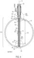
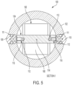
- FIGS. shows a section view of FIGS. 2 along section lines III-III. It is noted that although section lines III-III appears in the center, i.e., along axis 114, it is offset such that the FIG. 3 shows only certain components in section as will be evident from the remaining disclosure.
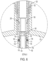
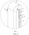
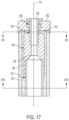
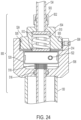
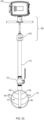
- the sensor head 100 is affixed to large diameter stem 132 at the stem cap 136. Large diameter stem transitions to a small diameter stem 134.
- the stem (including large diameter stem 132 and small diameter stem 134) may be formed as a single piece, or may be formed in several pieces and then joined together using known machining methods.
- the stem may be formed of, for example, stainless or other types of steel or steel alloys, for example 316 stainless steel. However, any material having sufficient strength for installation and under system operating conditions is suitable. Supporting the large diameter stem 132 and small diameter stem 134 is anchor 140, which will be discussed further below.
- Sensor head tube 102 may be made out of any easily machinable material which can withstand system temperatures and pressures including plastic and metal.
- sensor head tube includes acetal polymers.
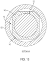
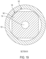
- Head tube 102 may also be over molded over the coil 180 and electrodes 105, 106, 107, 108, 109, 110.
- AC alternating current
- the conductive fluid flows through the magnetic field in the direction of system flow 172 ( FIG. 1 ).
- the conductor (i.e., the conductive fluid) passing through the magnetic field induces an electric potential and current according to Faraday's law, which is indicative of the flow velocity. This voltage is measured between top electrodes 105, 106 and bottom electrodes 107, 108, respectively, to determine the flow rate of the liquid.
- connection features are formed directly on the large diameter stem 132, i.e., there is no separate stem cap 136.
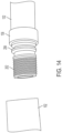
- the end of large diameter stem 132 can be directly threaded or machined in order to provide the shaft threaded portion 202 and ledge 204.
- a head tube threaded portion 208 is formed which matches the thread of shaft threaded portion 202.
- a lip 210 is formed in between the head tube threaded portion 208 and the connecting end of sensor head tube 102.
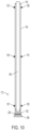
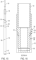
- the lip 210 is sized such that sensor head tube 102 and lip 210 can deform sufficient enough to be pressed over ledge 204 when fastening the large diameter stem 132 and sensor head tube 102 together by hand and resulting in a snap-fit 200 ( FIG. 16 ).
- the snap-fit may be improved with o-ring 212.
- the junction includes both threads and snap-fit such that the threads, when the junction is being twisted assists in pressing the lip 210 over ledge 204. It should be noted that although embodiments are shown with a snap-fit feature, other embodiments may not include a snap-fit feature.
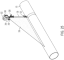
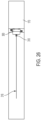
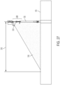
- the light plane 316 extends as a line about four to five feet away from valve 120, then a one degree rotation error will be even more apparent.
- the line will, in one example, be several feet long, e.g., 45.72 - 91.44 cm (18 - 36 inches), but will vary depending on the height of the sensor and the specific laser. The longer the line, the more accurate the alignment can be. Small discrepancies in angle will be multiplied by the length of the line to be easily identified and corrected for by turning the small diameter stem until the line is straight. Marking a straight line down the center of the pipe can further improve accuracy. The small diameter stem 134 would then be rotated until the laser line directly overlapped the marked line. This would further guarantee an accurate alignment.
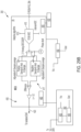
- Integrator 412 provides negative feedback at 414 to AC couple the signal.
- the resulting analog signal is then pre-filtered through low pass filter (LPF) 416 for filtering to remove high frequency noise and to provide more gain.
- LPF low pass filter
- the signal is sent to BIAS 418 for final gain and appropriate bias to maximize the input resolution for digital processing at ADC 415.
- the gain and filter stage LPF 416 is designed so that its bandwidth is significantly lower than the bandwidth of the digital filter 417, ensuring that no aliasing of higher frequency signals would hamper the output of the digital filter 417. Further, the gain is adjusted to provide enough amplification to maximize the ADC's input range. In order to avoid "clipping" of the noise spikes, which creates harmonic distortion of the signal, the output of the filter is biased to the half-supply point, before being digitized.
Landscapes
- Physics & Mathematics (AREA)
- Fluid Mechanics (AREA)
- General Physics & Mathematics (AREA)
- Electromagnetism (AREA)
- Measuring Volume Flow (AREA)
- Measuring Fluid Pressure (AREA)
Claims (13)
- Un ensemble capteur (101) comprenant:une tige;une tête de capteur (100) connectée à la tige comprenant au moins une électrode supérieure (105, 106) et au moins une électrode inférieure (107, 108); etune bobine de champ (180) configurée pour émettre un champ magnétique alternatif lorsqu'elle est alimentée par un courant alternatif,caractérisée en ce que les au moins une électrodes supérieure (105, 106) et inférieure (107, 108) sont configurées pour mesurer un potentiel de tension d'un fluide conducteur à travers l'électrode supérieure (105, 106) et l'électrode inférieure (107, 108) lorsque la tête de capteur (100) est insérée dans un tuyau d'écoulement (170) ayant une surface circonférentielle intérieure (173), où l'au moins une électrode supérieure (105, 106) est à proximité d'une première partie de la surface circonférentielle intérieure (173) du tuyau d'écoulement (170) lorsque l'ensemble capteur (101) est inséré dans le tuyau d'écoulement (170) et l'au moins une électrode inférieure (107, 108) est proche d'une deuxième partie de la surface circonférentielle intérieure (173) du tuyau d'écoulement (170) lorsque l'ensemble capteur (101) est inséré dans le tuyau d'écoulement (170), et les première et deuxième parties sont diamétralement opposées.
- Ensemble capteur (101) selon la revendication 1, où la tête de capteur (100) est fixée à la tige via une connexion filetée.
- Ensemble capteur (101) selon la revendication 1, où la tête de capteur (100) est fixée à une tige et la tige a une partie de grand diamètre (132) et une partie de petit diamètre (134), la partie de grand diamètre (132) étant plus proche de la tête de capteur (100) que la partie de petit diamètre (134).
- Ensemble capteur (101) selon la revendication 3, où la tige comprend une ancre (140) connectée de manière fixe à la partie de grand diamètre (132) et à la partie de petit diamètre (134), l'ancre (140) ayant une surface de section transversale plus grande que la partie de petit diamètre (134), à travers chacun de leurs axes longitudinaux respectifs, fournissant ainsi un avantage mécanique hydraulique pour une force exercée contre la partie de petit diamètre (134).
- Ensemble capteur (101) selon la revendication 4, où l'ensemble de capteur (101) comprend en outre un adaptateur de prise directe (130), et le diamètre extérieur de l'ancre est inférieur à un diamètre intérieur de l'adaptateur de prise directe (130), optionnellement où l'ensemble de capteur (101) comprend en outre des espaces (142) entre l'ancre (140) et l'adaptateur de prise directe (130) pour permettre une égalisation de la pression à travers l'ancre (140), optionnellement où l'ensemble d'ancrage (140) est dimensionné pour s'adapter étroitement à l'intérieur de l'adaptateur de prise directe (130) afin de minimiser la déviation latérale de la tête de capteur (100) lorsqu'il est installé dans un tuyau d'écoulement (170).
- Ensemble capteur (101) selon la revendication 1, comprenant plus d'une bobine de champ (180), où la tête de capteur (100) comprend une âme (104) et les bobines de champ (180) sont enroulées autour d'un premier et d'un deuxième côtés de l'âme (104), optionnellement où la tête de capteur (100) est moulée et/ou surmoulée sur l'âme (104) et/ou les électrodes (105, 106, 107, 108, 109, 110).
- Ensemble capteur (101) selon la revendication 6, où l'âme (104) comprend des canaux (350) le long de troisième et quatrième côtés de l'âme (104) et les canaux (350) sont parallèles à un axe longitudinal central de l'âme (104), éventuellement où la tête de capteur (100) comprend au moins un fil d'électrode (112) dans les canaux (350) et plus optionnellement où la tête de capteur (100) comprend au moins une entretoise (116) dans le canal de sorte que le fil d'électrode (112) est entre l'entretoise (116) et l'axe longitudinal central de l'âme (104).
- Ensemble capteur (101) selon la revendication 7, où une partie des canaux (350) se trouve dans une région de champ magnétique inférieur lorsque les bobines de champ (180) sont alimentées, optionnellement où la tige peut tourner avant pendant et après l'insertion de la tête de capteur (100) dans le tuyau d'écoulement (170) et indépendamment d'un adaptateur de prise directe correctement scellé (130).
- Ensemble capteur (101) selon la revendication 1, comprenant en outre un dispositif d'insertion mécanique (260), le dispositif d'insertion mécanique (260) comprenant un capuchon d'étanchéité supérieur (252), une plaque de réglage supérieure (154), optionnellement où la tige passe à travers le capuchon d'étanchéité supérieur (252) et la plaque de réglage supérieure (154) et l'ensemble capteur (101) comprend en outre un ressort (152) et un collier (150) chacun entourant au moins partiellement circonférentiellement la tige entre le capuchon d'étanchéité supérieur (252 ) et la plaque supérieure de réglage (154).
- Ensemble capteur (101) selon la revendication 8, comprenant en outre une lumière à émission de ligne attachée à la tige et configurée pour émettre une ligne sur la surface extérieure du tuyau (170) pendant et/ou après l'insertion de l'ensemble capteur (101) dans le tuyau (170).
- Ensemble capteur (101) selon la revendication 1, comprenant en outre un contrôleur (300, 455), où le contrôleur (300, 455) est adapté pour générer une source de courant de bobine de champ de courant alternatif, mesurer la tension aux bornes de l'au moins une électrodes supérieure (105, 106) et inférieure (107, 108), et pour amplifier et filtrer un signal résultant, optionnellement
où le contrôleur (455) est en outre configuré pour surveiller l'entrée et la sortie du signal et examiner deux impulsions successives, de signe opposé, et utiliser ces informations pour redresser le signal, filtrer le bruit et s'adapter à d'importants changements d'entrée. - Ensemble capteur (101) selon la revendication 1, comprenant en outre un dispositif d'insertion mécanique, le dispositif d'insertion mécanique (500) comprenant un écrou de précharge (504) et un logement de prise directe (506), optionnellement comprenant en outre un collier (522) et un ressort de positionnement (518), optionnellement comprenant en outre un ressort principal (510).
- Ensemble capteur (101) selon la revendication 1, où la tête de capteur est dimensionnée de sorte que la tête de capteur entre en contact avec la deuxième partie de la surface circonférentielle intérieure du tuyau d'écoulement lorsque l'ensemble de capteur est inséré dans le tuyau d'écoulement.
Priority Applications (1)
| Application Number | Priority Date | Filing Date | Title |
|---|---|---|---|
| EP23177657.6A EP4235113A3 (fr) | 2017-12-28 | 2018-12-27 | Ensemble capteur monolithique évolutif, dispositif de commande et procédés de fabrication et d'installation associés |
Applications Claiming Priority (2)
| Application Number | Priority Date | Filing Date | Title |
|---|---|---|---|
| US201762611251P | 2017-12-28 | 2017-12-28 | |
| PCT/US2018/067681 WO2019133716A1 (fr) | 2017-12-28 | 2018-12-27 | Ensemble capteur monolithique évolutif, dispositif de commande et procédés de fabrication et d'installation associés |
Related Child Applications (1)
| Application Number | Title | Priority Date | Filing Date |
|---|---|---|---|
| EP23177657.6A Division EP4235113A3 (fr) | 2017-12-28 | 2018-12-27 | Ensemble capteur monolithique évolutif, dispositif de commande et procédés de fabrication et d'installation associés |
Publications (3)
| Publication Number | Publication Date |
|---|---|
| EP3732446A1 EP3732446A1 (fr) | 2020-11-04 |
| EP3732446A4 EP3732446A4 (fr) | 2021-10-20 |
| EP3732446B1 true EP3732446B1 (fr) | 2023-06-07 |
Family
ID=67059472
Family Applications (2)
| Application Number | Title | Priority Date | Filing Date |
|---|---|---|---|
| EP23177657.6A Pending EP4235113A3 (fr) | 2017-12-28 | 2018-12-27 | Ensemble capteur monolithique évolutif, dispositif de commande et procédés de fabrication et d'installation associés |
| EP18894480.5A Active EP3732446B1 (fr) | 2017-12-28 | 2018-12-27 | Ensemble capteur monolithique évolutif, dispositif de commande et procédés de fabrication et d'installation associés |
Family Applications Before (1)
| Application Number | Title | Priority Date | Filing Date |
|---|---|---|---|
| EP23177657.6A Pending EP4235113A3 (fr) | 2017-12-28 | 2018-12-27 | Ensemble capteur monolithique évolutif, dispositif de commande et procédés de fabrication et d'installation associés |
Country Status (7)
| Country | Link |
|---|---|
| US (3) | US10724880B2 (fr) |
| EP (2) | EP4235113A3 (fr) |
| CN (2) | CN120252872A (fr) |
| CA (1) | CA3087337A1 (fr) |
| DK (1) | DK3732446T3 (fr) |
| MX (2) | MX2020006885A (fr) |
| WO (1) | WO2019133716A1 (fr) |
Families Citing this family (7)
| Publication number | Priority date | Publication date | Assignee | Title |
|---|---|---|---|---|
| US11181409B2 (en) | 2018-08-09 | 2021-11-23 | General Electric Company | Monitoring and control system for a flow duct |
| MX2021008511A (es) | 2019-02-22 | 2021-08-19 | Onicon Incorporated | Medidores magneticos de insercion mejorados y metodos. |
| US11187560B2 (en) * | 2019-10-03 | 2021-11-30 | General Electric Company | Probe-based circumferential traversing system |
| CN112944025A (zh) * | 2021-03-24 | 2021-06-11 | 山东齐芯智控科技有限公司 | 精确计量的供热控制阀门 |
| CN114279507B (zh) * | 2021-12-24 | 2025-01-28 | 江苏鑫华禹测控技术有限公司 | 一种具有防护功能的电磁流量表 |
| DE102022129631A1 (de) * | 2022-11-09 | 2024-05-16 | Endress+Hauser Flowtec Ag | Montagewerkzeug zur Montage eines einsteckbaren Durchflussmessgeräts und Verfahren zur Einrichtung eines solchen Durchflussmessgerät |
| JP2025003131A (ja) * | 2023-06-23 | 2025-01-09 | 横河電機株式会社 | 流路装置 |
Family Cites Families (40)
| Publication number | Priority date | Publication date | Assignee | Title |
|---|---|---|---|---|
| US4117720A (en) * | 1976-12-06 | 1978-10-03 | Sybron Corporation | Electric measuring device having a small-bore liquid container with improved electrode sealing means |
| CN2112804U (zh) * | 1991-07-15 | 1992-08-12 | 天津市自动化仪表三厂 | 插入式电磁流量传感器 |
| JP2966187B2 (ja) * | 1991-08-14 | 1999-10-25 | 株式会社神戸製鋼所 | 圧延機 |
| US5303602A (en) * | 1992-03-13 | 1994-04-19 | Veris, Inc. | Tool for inserting and removing a sensing element from a fluid pipeline |
| US5410920A (en) * | 1994-01-28 | 1995-05-02 | Veris, Inc. | Apparatus for inserting and removing a sensing element from a fluid pipeline |
| JP3132628B2 (ja) * | 1994-07-21 | 2001-02-05 | 富士電機株式会社 | コリオリ式質量流量計 |
| US5529087A (en) * | 1995-02-27 | 1996-06-25 | Lockheed Idaho Technologies Company | System for remotely servicing a top loading captive ball valve |
| US5670724A (en) | 1996-05-01 | 1997-09-23 | Amj Equipment Corporation | Apparatus for sensing liquid flow and pressure in a conduit and associated methods |
| US6514346B1 (en) * | 1998-03-25 | 2003-02-04 | Neuco, Inc. | Method and apparatus for inserting and propelling a coating device into and through live gas pipeline |
| CN2417461Y (zh) * | 2000-02-16 | 2001-01-31 | 徐连粮 | 插入式多电极成相电磁流量计 |
| RU14783U1 (ru) * | 2000-03-09 | 2000-08-27 | Открытое акционерное общество "Инженерно-производственная фирма "Сибнефтеавтоматика" | Электромагнитный расходомер |
| US6422531B1 (en) * | 2000-06-28 | 2002-07-23 | Wabtec Corporation | ECP manifold valve inserts |
| US6286553B1 (en) | 2000-09-01 | 2001-09-11 | Tdw Delaware, Inc. | Removable closure system |
| US6463807B1 (en) * | 2000-11-02 | 2002-10-15 | Murray F. Feller | Magnetic flow sensor and method |
| US6431011B1 (en) * | 2000-11-02 | 2002-08-13 | Murray F. Feller | Magnetic flow sensor and method |
| JP2007147631A (ja) * | 2001-02-19 | 2007-06-14 | Hitachi Ltd | 挿入形電磁流速計 |
| US20120149985A1 (en) | 2007-05-18 | 2012-06-14 | Frassica James J | Rotate-to-advance catheterization system |
| US8915453B1 (en) * | 2007-06-01 | 2014-12-23 | Raymond C. Sherry | Expansion nozzle with continuous rotating stem |
| CN101339060B (zh) * | 2007-07-03 | 2010-06-23 | 上海星空自动化仪表有限公司 | 用户可送检大口径电磁流量计 |
| DE102007056544A1 (de) * | 2007-11-23 | 2009-05-28 | Robert Bosch Gmbh | Sensoranordnung zur Bestimmung eines Tankfüllstands und Verfahren zur Herstellung hierzu |
| EP2166423B1 (fr) | 2008-09-19 | 2017-12-20 | Isomatic A/S | Vanne de liquide équilibrée |
| CN101368834B (zh) * | 2008-09-24 | 2010-09-22 | 上海大学 | 多电极插入式电磁流量计传感器 |
| US7571655B1 (en) | 2008-11-28 | 2009-08-11 | Murray F Feller | Magnetic flow meter with buffering electrodes |
| RU2503930C2 (ru) | 2009-05-11 | 2014-01-10 | Майкро Моушн, Инк. | Расходомер, включающий в себя сбалансированную опорную деталь |
| JP2011017632A (ja) | 2009-07-09 | 2011-01-27 | Tamura Seisakusho Co Ltd | フラックスゲート漏電センサ |
| US8136410B2 (en) * | 2010-01-06 | 2012-03-20 | Mccrometer, Inc. | Sensor assembly for a fluid flowmeter |
| US8714028B2 (en) | 2010-03-01 | 2014-05-06 | Cla-Val Co. | Insertion vortex fluid flow meter with adjustable geometry |
| US9182258B2 (en) | 2011-06-28 | 2015-11-10 | Rosemount Inc. | Variable frequency magnetic flowmeter |
| US8997580B2 (en) * | 2012-09-07 | 2015-04-07 | Mccrometer, Inc. | Angled insert magnetic flow meter |
| CN202974352U (zh) * | 2012-12-12 | 2013-06-05 | 承德市本特思达仪表有限公司 | 一种插入式电磁流量计 |
| CN203132610U (zh) * | 2012-12-28 | 2013-08-14 | 重庆川仪自动化股份有限公司 | 多传感器插入式电磁流量计 |
| CN203132614U (zh) * | 2013-03-19 | 2013-08-14 | 开封开流仪表有限公司 | 一体型插入式电池供电电磁流量计 |
| US9541432B2 (en) | 2013-05-17 | 2017-01-10 | The United States Of America As Represented By The Administrator Of The U.S. Environmental Protection Agency | Flow imaging and monitoring for synchronized management of wide area drainage |
| CN203432628U (zh) * | 2013-05-21 | 2014-02-12 | 艾默生过程控制流量技术有限公司 | 电极组件、电磁流量计和现场仪表 |
| US20150211686A1 (en) | 2014-01-30 | 2015-07-30 | Clarence DYCK | Method and apparatus for abandoning or isolating an underground pipeline |
| US9410830B2 (en) | 2014-06-30 | 2016-08-09 | Micro Motion, Inc. | Magnetic flowmeter flowtube assembly with interchangeable liner/electrode module |
| US9551601B2 (en) * | 2014-12-30 | 2017-01-24 | Dieterich Standard, Inc. | Variable line size averaging pitot tube |
| CN205192547U (zh) * | 2015-04-27 | 2016-04-27 | 艾默生过程控制流量技术有限公司 | 弹簧组件以及使用其的电极组件 |
| WO2017132942A1 (fr) | 2016-02-04 | 2017-08-10 | 金宙科技有限公司 | Dispositif de mesure de l'écoulement d'un liquide |
| CN105928573A (zh) * | 2016-05-30 | 2016-09-07 | 铜陵市东方矿冶机械有限责任公司 | 插入式电磁流量计 |
-
2018
- 2018-12-27 CN CN202510413453.5A patent/CN120252872A/zh active Pending
- 2018-12-27 US US16/233,915 patent/US10724880B2/en active Active
- 2018-12-27 MX MX2020006885A patent/MX2020006885A/es unknown
- 2018-12-27 EP EP23177657.6A patent/EP4235113A3/fr active Pending
- 2018-12-27 WO PCT/US2018/067681 patent/WO2019133716A1/fr not_active Ceased
- 2018-12-27 CA CA3087337A patent/CA3087337A1/fr active Pending
- 2018-12-27 EP EP18894480.5A patent/EP3732446B1/fr active Active
- 2018-12-27 DK DK18894480.5T patent/DK3732446T3/da active
- 2018-12-27 CN CN201880089234.4A patent/CN111936826A/zh active Pending
-
2020
- 2020-07-09 US US16/924,358 patent/US11467013B2/en active Active
- 2020-07-13 MX MX2024000351A patent/MX2024000351A/es unknown
-
2022
- 2022-09-19 US US17/947,802 patent/US12510389B2/en active Active
Also Published As
| Publication number | Publication date |
|---|---|
| CA3087337A1 (fr) | 2019-07-04 |
| US10724880B2 (en) | 2020-07-28 |
| EP3732446A1 (fr) | 2020-11-04 |
| US12510389B2 (en) | 2025-12-30 |
| WO2019133716A1 (fr) | 2019-07-04 |
| CN120252872A (zh) | 2025-07-04 |
| MX2020006885A (es) | 2021-01-15 |
| US20230009920A1 (en) | 2023-01-12 |
| US20190204129A1 (en) | 2019-07-04 |
| EP4235113A3 (fr) | 2023-10-04 |
| MX2024000351A (es) | 2024-01-26 |
| EP4235113A2 (fr) | 2023-08-30 |
| DK3732446T3 (da) | 2023-09-04 |
| US11467013B2 (en) | 2022-10-11 |
| EP3732446A4 (fr) | 2021-10-20 |
| US20200340837A1 (en) | 2020-10-29 |
| CN111936826A (zh) | 2020-11-13 |
Similar Documents
| Publication | Publication Date | Title |
|---|---|---|
| US12510389B2 (en) | Scalable monolithic sensor assembly, controller, and methods of making and installing same | |
| US8555918B2 (en) | Flow rate control valve and spool position detection device for the flow rate control valve | |
| US6605940B1 (en) | Linear variable differential transformer assembly with nulling adjustment and process for nulling adjustment | |
| CA2757978C (fr) | Ensemble capteur pour debitmetre de fluide | |
| US10655651B2 (en) | Rotary actuator with position feedback device and process valve module | |
| GB2068560A (en) | Electrical transducer responsive to fluid flow | |
| US8274287B2 (en) | Metallic debris detection sensor | |
| JP2013007745A (ja) | データム調整を伴う誘導センサ | |
| CN113474564B (zh) | 改进的插入式磁性仪表和方法 | |
| CA3128391C (fr) | Compteurs magnetiques a insertion amelioree et procedes | |
| WO2019064269A1 (fr) | Capteur courbé de transducteur de position | |
| US20070145969A1 (en) | Long stroke hall position sensor having a shaped pole | |
| CN1507638A (zh) | 电磁调节装置 | |
| EP3628982B1 (fr) | Ensemble de débitmètre magnétique à passage intégral | |
| US8408230B2 (en) | Temperature compensated I/P converter | |
| KR101896277B1 (ko) | 전기 전도도 센서 | |
| KR820001105B1 (ko) | 인테그랄 휠드 자기유량계 | |
| HK1166847B (en) | Sensor assembly for a fluid flowmeter | |
| CN102720718A (zh) | 一种无杆内藏集成式宽带动态缸 |
Legal Events
| Date | Code | Title | Description |
|---|---|---|---|
| STAA | Information on the status of an ep patent application or granted ep patent |
Free format text: STATUS: THE INTERNATIONAL PUBLICATION HAS BEEN MADE |
|
| PUAI | Public reference made under article 153(3) epc to a published international application that has entered the european phase |
Free format text: ORIGINAL CODE: 0009012 |
|
| STAA | Information on the status of an ep patent application or granted ep patent |
Free format text: STATUS: REQUEST FOR EXAMINATION WAS MADE |
|
| 17P | Request for examination filed |
Effective date: 20200728 |
|
| AK | Designated contracting states |
Kind code of ref document: A1 Designated state(s): AL AT BE BG CH CY CZ DE DK EE ES FI FR GB GR HR HU IE IS IT LI LT LU LV MC MK MT NL NO PL PT RO RS SE SI SK SM TR |
|
| AX | Request for extension of the european patent |
Extension state: BA ME |
|
| DAV | Request for validation of the european patent (deleted) | ||
| DAX | Request for extension of the european patent (deleted) | ||
| A4 | Supplementary search report drawn up and despatched |
Effective date: 20210922 |
|
| RIC1 | Information provided on ipc code assigned before grant |
Ipc: G01F 1/56 20060101ALI20210916BHEP Ipc: G01F 1/00 20060101ALI20210916BHEP Ipc: G01F 1/58 20060101AFI20210916BHEP |
|
| GRAP | Despatch of communication of intention to grant a patent |
Free format text: ORIGINAL CODE: EPIDOSNIGR1 |
|
| STAA | Information on the status of an ep patent application or granted ep patent |
Free format text: STATUS: GRANT OF PATENT IS INTENDED |
|
| INTG | Intention to grant announced |
Effective date: 20221018 |
|
| RAP3 | Party data changed (applicant data changed or rights of an application transferred) |
Owner name: ONICON INCORPORATED |
|
| GRAS | Grant fee paid |
Free format text: ORIGINAL CODE: EPIDOSNIGR3 |
|
| GRAA | (expected) grant |
Free format text: ORIGINAL CODE: 0009210 |
|
| STAA | Information on the status of an ep patent application or granted ep patent |
Free format text: STATUS: THE PATENT HAS BEEN GRANTED |
|
| AK | Designated contracting states |
Kind code of ref document: B1 Designated state(s): AL AT BE BG CH CY CZ DE DK EE ES FI FR GB GR HR HU IE IS IT LI LT LU LV MC MK MT NL NO PL PT RO RS SE SI SK SM TR |
|
| REG | Reference to a national code |
Ref country code: GB Ref legal event code: FG4D |
|
| REG | Reference to a national code |
Ref country code: CH Ref legal event code: EP Ref country code: AT Ref legal event code: REF Ref document number: 1576380 Country of ref document: AT Kind code of ref document: T Effective date: 20230615 |
|
| REG | Reference to a national code |
Ref country code: DE Ref legal event code: R096 Ref document number: 602018051644 Country of ref document: DE |
|
| P01 | Opt-out of the competence of the unified patent court (upc) registered |
Effective date: 20230601 |
|
| REG | Reference to a national code |
Ref country code: DK Ref legal event code: T3 Effective date: 20230829 |
|
| REG | Reference to a national code |
Ref country code: SE Ref legal event code: TRGR |
|
| REG | Reference to a national code |
Ref country code: LT Ref legal event code: MG9D |
|
| REG | Reference to a national code |
Ref country code: NL Ref legal event code: MP Effective date: 20230607 |
|
| PG25 | Lapsed in a contracting state [announced via postgrant information from national office to epo] |
Ref country code: NO Free format text: LAPSE BECAUSE OF FAILURE TO SUBMIT A TRANSLATION OF THE DESCRIPTION OR TO PAY THE FEE WITHIN THE PRESCRIBED TIME-LIMIT Effective date: 20230907 Ref country code: ES Free format text: LAPSE BECAUSE OF FAILURE TO SUBMIT A TRANSLATION OF THE DESCRIPTION OR TO PAY THE FEE WITHIN THE PRESCRIBED TIME-LIMIT Effective date: 20230607 |
|
| REG | Reference to a national code |
Ref country code: AT Ref legal event code: MK05 Ref document number: 1576380 Country of ref document: AT Kind code of ref document: T Effective date: 20230607 |
|
| PG25 | Lapsed in a contracting state [announced via postgrant information from national office to epo] |
Ref country code: RS Free format text: LAPSE BECAUSE OF FAILURE TO SUBMIT A TRANSLATION OF THE DESCRIPTION OR TO PAY THE FEE WITHIN THE PRESCRIBED TIME-LIMIT Effective date: 20230607 Ref country code: NL Free format text: LAPSE BECAUSE OF FAILURE TO SUBMIT A TRANSLATION OF THE DESCRIPTION OR TO PAY THE FEE WITHIN THE PRESCRIBED TIME-LIMIT Effective date: 20230607 Ref country code: LV Free format text: LAPSE BECAUSE OF FAILURE TO SUBMIT A TRANSLATION OF THE DESCRIPTION OR TO PAY THE FEE WITHIN THE PRESCRIBED TIME-LIMIT Effective date: 20230607 Ref country code: LT Free format text: LAPSE BECAUSE OF FAILURE TO SUBMIT A TRANSLATION OF THE DESCRIPTION OR TO PAY THE FEE WITHIN THE PRESCRIBED TIME-LIMIT Effective date: 20230607 Ref country code: HR Free format text: LAPSE BECAUSE OF FAILURE TO SUBMIT A TRANSLATION OF THE DESCRIPTION OR TO PAY THE FEE WITHIN THE PRESCRIBED TIME-LIMIT Effective date: 20230607 Ref country code: GR Free format text: LAPSE BECAUSE OF FAILURE TO SUBMIT A TRANSLATION OF THE DESCRIPTION OR TO PAY THE FEE WITHIN THE PRESCRIBED TIME-LIMIT Effective date: 20230908 |
|
| PGFP | Annual fee paid to national office [announced via postgrant information from national office to epo] |
Ref country code: DK Payment date: 20230907 Year of fee payment: 6 |
|
| PG25 | Lapsed in a contracting state [announced via postgrant information from national office to epo] |
Ref country code: FI Free format text: LAPSE BECAUSE OF FAILURE TO SUBMIT A TRANSLATION OF THE DESCRIPTION OR TO PAY THE FEE WITHIN THE PRESCRIBED TIME-LIMIT Effective date: 20230607 |
|
| PG25 | Lapsed in a contracting state [announced via postgrant information from national office to epo] |
Ref country code: SK Free format text: LAPSE BECAUSE OF FAILURE TO SUBMIT A TRANSLATION OF THE DESCRIPTION OR TO PAY THE FEE WITHIN THE PRESCRIBED TIME-LIMIT Effective date: 20230607 |
|
| PG25 | Lapsed in a contracting state [announced via postgrant information from national office to epo] |
Ref country code: IS Free format text: LAPSE BECAUSE OF FAILURE TO SUBMIT A TRANSLATION OF THE DESCRIPTION OR TO PAY THE FEE WITHIN THE PRESCRIBED TIME-LIMIT Effective date: 20231007 |
|
| PG25 | Lapsed in a contracting state [announced via postgrant information from national office to epo] |
Ref country code: SM Free format text: LAPSE BECAUSE OF FAILURE TO SUBMIT A TRANSLATION OF THE DESCRIPTION OR TO PAY THE FEE WITHIN THE PRESCRIBED TIME-LIMIT Effective date: 20230607 Ref country code: SK Free format text: LAPSE BECAUSE OF FAILURE TO SUBMIT A TRANSLATION OF THE DESCRIPTION OR TO PAY THE FEE WITHIN THE PRESCRIBED TIME-LIMIT Effective date: 20230607 Ref country code: RO Free format text: LAPSE BECAUSE OF FAILURE TO SUBMIT A TRANSLATION OF THE DESCRIPTION OR TO PAY THE FEE WITHIN THE PRESCRIBED TIME-LIMIT Effective date: 20230607 Ref country code: PT Free format text: LAPSE BECAUSE OF FAILURE TO SUBMIT A TRANSLATION OF THE DESCRIPTION OR TO PAY THE FEE WITHIN THE PRESCRIBED TIME-LIMIT Effective date: 20231009 Ref country code: IS Free format text: LAPSE BECAUSE OF FAILURE TO SUBMIT A TRANSLATION OF THE DESCRIPTION OR TO PAY THE FEE WITHIN THE PRESCRIBED TIME-LIMIT Effective date: 20231007 Ref country code: EE Free format text: LAPSE BECAUSE OF FAILURE TO SUBMIT A TRANSLATION OF THE DESCRIPTION OR TO PAY THE FEE WITHIN THE PRESCRIBED TIME-LIMIT Effective date: 20230607 Ref country code: AT Free format text: LAPSE BECAUSE OF FAILURE TO SUBMIT A TRANSLATION OF THE DESCRIPTION OR TO PAY THE FEE WITHIN THE PRESCRIBED TIME-LIMIT Effective date: 20230607 |
|
| PGFP | Annual fee paid to national office [announced via postgrant information from national office to epo] |
Ref country code: SE Payment date: 20231227 Year of fee payment: 6 |
|
| PG25 | Lapsed in a contracting state [announced via postgrant information from national office to epo] |
Ref country code: PL Free format text: LAPSE BECAUSE OF FAILURE TO SUBMIT A TRANSLATION OF THE DESCRIPTION OR TO PAY THE FEE WITHIN THE PRESCRIBED TIME-LIMIT Effective date: 20230607 |
|
| REG | Reference to a national code |
Ref country code: DE Ref legal event code: R097 Ref document number: 602018051644 Country of ref document: DE |
|
| PLBE | No opposition filed within time limit |
Free format text: ORIGINAL CODE: 0009261 |
|
| STAA | Information on the status of an ep patent application or granted ep patent |
Free format text: STATUS: NO OPPOSITION FILED WITHIN TIME LIMIT |
|
| PG25 | Lapsed in a contracting state [announced via postgrant information from national office to epo] |
Ref country code: SI Free format text: LAPSE BECAUSE OF FAILURE TO SUBMIT A TRANSLATION OF THE DESCRIPTION OR TO PAY THE FEE WITHIN THE PRESCRIBED TIME-LIMIT Effective date: 20230607 |
|
| 26N | No opposition filed |
Effective date: 20240308 |
|
| PG25 | Lapsed in a contracting state [announced via postgrant information from national office to epo] |
Ref country code: SI Free format text: LAPSE BECAUSE OF FAILURE TO SUBMIT A TRANSLATION OF THE DESCRIPTION OR TO PAY THE FEE WITHIN THE PRESCRIBED TIME-LIMIT Effective date: 20230607 Ref country code: IT Free format text: LAPSE BECAUSE OF FAILURE TO SUBMIT A TRANSLATION OF THE DESCRIPTION OR TO PAY THE FEE WITHIN THE PRESCRIBED TIME-LIMIT Effective date: 20230607 |
|
| REG | Reference to a national code |
Ref country code: DE Ref legal event code: R119 Ref document number: 602018051644 Country of ref document: DE |
|
| REG | Reference to a national code |
Ref country code: CH Ref legal event code: PL |
|
| PG25 | Lapsed in a contracting state [announced via postgrant information from national office to epo] |
Ref country code: LU Free format text: LAPSE BECAUSE OF NON-PAYMENT OF DUE FEES Effective date: 20231227 |
|
| PG25 | Lapsed in a contracting state [announced via postgrant information from national office to epo] |
Ref country code: MC Free format text: LAPSE BECAUSE OF FAILURE TO SUBMIT A TRANSLATION OF THE DESCRIPTION OR TO PAY THE FEE WITHIN THE PRESCRIBED TIME-LIMIT Effective date: 20230607 |
|
| REG | Reference to a national code |
Ref country code: BE Ref legal event code: MM Effective date: 20231231 |
|
| PG25 | Lapsed in a contracting state [announced via postgrant information from national office to epo] |
Ref country code: MC Free format text: LAPSE BECAUSE OF FAILURE TO SUBMIT A TRANSLATION OF THE DESCRIPTION OR TO PAY THE FEE WITHIN THE PRESCRIBED TIME-LIMIT Effective date: 20230607 Ref country code: LU Free format text: LAPSE BECAUSE OF NON-PAYMENT OF DUE FEES Effective date: 20231227 |
|
| PG25 | Lapsed in a contracting state [announced via postgrant information from national office to epo] |
Ref country code: DE Free format text: LAPSE BECAUSE OF NON-PAYMENT OF DUE FEES Effective date: 20240702 |
|
| PG25 | Lapsed in a contracting state [announced via postgrant information from national office to epo] |
Ref country code: BE Free format text: LAPSE BECAUSE OF NON-PAYMENT OF DUE FEES Effective date: 20231231 |
|
| PG25 | Lapsed in a contracting state [announced via postgrant information from national office to epo] |
Ref country code: FR Free format text: LAPSE BECAUSE OF NON-PAYMENT OF DUE FEES Effective date: 20231231 |
|
| PG25 | Lapsed in a contracting state [announced via postgrant information from national office to epo] |
Ref country code: CH Free format text: LAPSE BECAUSE OF NON-PAYMENT OF DUE FEES Effective date: 20231231 |
|
| PG25 | Lapsed in a contracting state [announced via postgrant information from national office to epo] |
Ref country code: FR Free format text: LAPSE BECAUSE OF NON-PAYMENT OF DUE FEES Effective date: 20231231 Ref country code: DE Free format text: LAPSE BECAUSE OF NON-PAYMENT OF DUE FEES Effective date: 20240702 Ref country code: CH Free format text: LAPSE BECAUSE OF NON-PAYMENT OF DUE FEES Effective date: 20231231 Ref country code: BE Free format text: LAPSE BECAUSE OF NON-PAYMENT OF DUE FEES Effective date: 20231231 |
|
| PG25 | Lapsed in a contracting state [announced via postgrant information from national office to epo] |
Ref country code: BG Free format text: LAPSE BECAUSE OF FAILURE TO SUBMIT A TRANSLATION OF THE DESCRIPTION OR TO PAY THE FEE WITHIN THE PRESCRIBED TIME-LIMIT Effective date: 20230607 |
|
| PG25 | Lapsed in a contracting state [announced via postgrant information from national office to epo] |
Ref country code: BG Free format text: LAPSE BECAUSE OF FAILURE TO SUBMIT A TRANSLATION OF THE DESCRIPTION OR TO PAY THE FEE WITHIN THE PRESCRIBED TIME-LIMIT Effective date: 20230607 |
|
| PGFP | Annual fee paid to national office [announced via postgrant information from national office to epo] |
Ref country code: GB Payment date: 20241001 Year of fee payment: 7 |
|
| PGFP | Annual fee paid to national office [announced via postgrant information from national office to epo] |
Ref country code: CZ Payment date: 20241217 Year of fee payment: 7 Ref country code: IE Payment date: 20241001 Year of fee payment: 7 |
|
| REG | Reference to a national code |
Ref country code: DK Ref legal event code: EBP Effective date: 20241231 |
|
| PG25 | Lapsed in a contracting state [announced via postgrant information from national office to epo] |
Ref country code: CY Free format text: LAPSE BECAUSE OF FAILURE TO SUBMIT A TRANSLATION OF THE DESCRIPTION OR TO PAY THE FEE WITHIN THE PRESCRIBED TIME-LIMIT; INVALID AB INITIO Effective date: 20181227 |
|
| REG | Reference to a national code |
Ref country code: SE Ref legal event code: EUG |
|
| PG25 | Lapsed in a contracting state [announced via postgrant information from national office to epo] |
Ref country code: HU Free format text: LAPSE BECAUSE OF FAILURE TO SUBMIT A TRANSLATION OF THE DESCRIPTION OR TO PAY THE FEE WITHIN THE PRESCRIBED TIME-LIMIT; INVALID AB INITIO Effective date: 20181227 |
|
| PG25 | Lapsed in a contracting state [announced via postgrant information from national office to epo] |
Ref country code: TR Free format text: LAPSE BECAUSE OF FAILURE TO SUBMIT A TRANSLATION OF THE DESCRIPTION OR TO PAY THE FEE WITHIN THE PRESCRIBED TIME-LIMIT Effective date: 20230607 |
|
| PG25 | Lapsed in a contracting state [announced via postgrant information from national office to epo] |
Ref country code: DK Free format text: LAPSE BECAUSE OF NON-PAYMENT OF DUE FEES Effective date: 20241231 |