EP3732949A1 - Procédé de récolte d'un peuplement de plantes à récolter disposé dans un champ et moissonneuse-batteuse - Google Patents
Procédé de récolte d'un peuplement de plantes à récolter disposé dans un champ et moissonneuse-batteuse Download PDFInfo
- Publication number
- EP3732949A1 EP3732949A1 EP20150958.5A EP20150958A EP3732949A1 EP 3732949 A1 EP3732949 A1 EP 3732949A1 EP 20150958 A EP20150958 A EP 20150958A EP 3732949 A1 EP3732949 A1 EP 3732949A1
- Authority
- EP
- European Patent Office
- Prior art keywords
- crop
- combine harvester
- changed
- threshing
- beginning
- Prior art date
- Legal status (The legal status is an assumption and is not a legal conclusion. Google has not performed a legal analysis and makes no representation as to the accuracy of the status listed.)
- Granted
Links
Images


Classifications
-
- A—HUMAN NECESSITIES
- A01—AGRICULTURE; FORESTRY; ANIMAL HUSBANDRY; HUNTING; TRAPPING; FISHING
- A01D—HARVESTING; MOWING
- A01D41/00—Combines, i.e. harvesters or mowers combined with threshing devices
- A01D41/12—Details of combines
- A01D41/127—Control or measuring arrangements specially adapted for combines
Definitions
- the present application relates to a method for harvesting crops to be harvested arranged in a field by means of a combine harvester according to the preamble of claim 1.
- the present application also relates to a self-propelled combine harvester according to the preamble of claim 15.
- the respective inventory is processed in individual sections. These are typically formed by a plurality of working tracks that are successively traversed by the combine harvester until the entire crop has been swept over and thus all plants have been harvested.
- the sections are generally designed in the form of paths that are as straight as possible.
- the combine harvester enters the stock at the beginning of the processing of a respective section and leaves the crop again when the processing of the section is completed at the end of the crop.
- the combine then turns outside of the crop in the area of a headland of the field on which the crop is, and then starts working on the next section.
- the beginning of the stock and the end of the stock are conceptually differentiated depending on the processing of the stock by means of the combine harvester.
- the beginning of the crop always describes the transition at which the combine harvester enters the crop at the beginning of the processing of a respective section, while the end of the crop describes the transition at which the combine drives out of the crop at the end of a section.
- the area of the field outside the crop usually includes the headland.
- the threshing organ and the separating organ are configured in such a way that they are adapted to processing a maximum crop flow and, in the presence of such a feed, bring about the best possible separating performance with regard to the detachment of fruits from plant residues and then the separation of the fruit from the plant residues. If there is a non-maximum flow of harvested crop, as is the case in the manner described both when leaving the stand and when entering the stand, however, increased fruit losses can occur due to the setting of the working organs, which are undesirable.
- the object of the present invention is to provide a method by means of which the fruit losses in the course of entering the stand and moving it out of the stand can be reduced.
- the method according to the invention is characterized in that an area in front of the combine harvester is detected by means of at least one sensor device. This detection can in particular take place optically, the sensor device being formed by at least one camera. Using this procedure, the beginning or end of the inventory can be identified. The method according to the invention further provides that as a result of this recognition of the beginning of the crop or the end of the crop, at least one operating parameter of the combine harvester is changed at least temporarily.
- the method according to the invention has many advantages. By detecting the area in front of the combine harvester, it is possible to determine a change in the crop before this actually results in a change in the crop throughput. In particular, the detection can take place without a measurement of a layer thickness of a crop flow that is processed in the combine harvester.
- the "area in front of" denotes an area that is located in front of the cutting unit, as seen in the direction of travel of the combine harvester.
- a combine harvester recognizes the same in the area in front of the combine harvester when it approaches the end of the crop and as a result can already make preparations for changing the at least one operating parameter, so that these become effective at the same time as a change in the crop throughput and not just afterwards on it.
- the change in the operating parameter does not therefore have to immediately follow the detection of the beginning or end of the inventory, but can in particular take place with a time offset. Knowing the driving speed of the combine harvester, for example, it is conceivable to determine a travel time starting from a current position of the combine harvester to the end of the crop and to change at least one operating parameter of the combine harvester adapted to this travel time. In other words, it is conceivable to plan an intermediate period between a detection time of the beginning or end of the inventory and a starting time for the change in the operating parameter. The intermediate period formed in this way can be, for example, 1 second, preferably several seconds.
- a plant density may decrease in an edge area of the stand starting from a maximum, which is present in a central area of the stand, towards the end of the stand. Consequently, it can make sense to continuously change at least one operating parameter from a starting value to a target value as the population approaches the end of the inventory (when moving out of the inventory) or vice versa with increasing distance from the beginning of the inventory (when entering the inventory).
- an increase in crop throughput to be processed by means of the combine is inferred and, when an end of crop is recognized, a decrease in crop throughput is concluded, which will soon occur.
- At least one parameter setting of at least one working organ of the combine is preferably changed as a function of this conclusion.
- the change in the parameter setting for example a speed of the threshing drum, can consequently take place in the direction of better efficiency in processing the crop flow, taking into account a falling or increasing crop throughput.
- parameter settings of the working elements of the combine harvester can be made in a targeted manner so that fruit losses are minimized.
- the process steps described are typical for the processing of a crop using a combine harvester.
- the plants are usually cut by means of a cutter bar which is arranged on a cutting unit.
- the separating element can in particular comprise a tray shaker or a separator rotor and a sieve device with a plurality of sieves.
- the process steps described can be used to harvest plants particularly efficiently.
- the fruits pass through openings in a sieve device of the separating element in the course of being separated by means of the separating element.
- the operating parameter "opening cross-sections of the sieve openings" is changed.
- the opening cross-sections are reduced. This is due to the fact that the crop throughput decreases after leaving the crop at the end of the crop, whereupon a layer thickness of the cut plants also decreases. This in turn has the consequence that non-fruit components unintentionally fall through the sieve device and are consequently conveyed together with the fruit into a grain tank. This effect can be avoided by reducing the opening cross-sections of the sieve openings, so that the contamination of the separated fruits is reduced.
- opening cross-sections of the sieve openings can in particular take place successively, with the opening cross-sections preferably being successively reduced in the course of moving out of the stock at the end of the stock.
- the operating parameter "opening cross-sections of the sieve openings" is changed as a result of the recognition of the beginning of the stock, the opening cross-sections preferably being enlarged.
- This procedure offers the advantage that the opening cross-sections, conversely analogous to the above description, are enlarged with an increasing crop throughput in order to achieve an optimal separation performance of the separating element. It is particularly advantageous if the opening cross-sections are changed starting from a minimum that is present when entering the crop at the beginning of the crop to a maximum that is present when a maximum crop throughput is reached.
- the separating element typically interacts with at least one fan which is arranged below at least one screen of the separating element.
- the fan By means of the fan, an air volume flow is generated, which flows through the sieve from its underside in the direction of its upper side, counter to the direction in which the fruit falls through the sieve openings. Since the plant residues, in addition to larger components that cannot pass through the sieve openings, also include smaller components, an air sifting is carried out by means of such a fan, by means of which the relatively heavy fruits, in particular grains, are separated from the relatively light small portions of the plant residues, e.g. to be separated.
- the air volume flow generated by the fan can inadvertently carry along and discharge fruits, which are then reflected as fruit losses. If such a fan is present, it is therefore particularly advantageous if the operating parameter "speed of the fan" is changed as a result of the end of the stock being recognized.
- the speed of the fan is preferably reduced. By reducing the speed of the fan, the air volume flow is reduced, which in the presence of a reduced layer thickness reduces the unintentional discharge of fruit, which is otherwise to be complained about.
- At least two operating parameters relating to the separating element are changed in the course of recognizing the end of the stock, namely on the one hand the operating parameter "opening cross-sections of the sieve openings" and on the other the operating parameter "speed of the fan". These two operating parameters are advantageously changed in coordination with one another in order to achieve the most optimal possible separation of fruits and light plant residues.
- the distance between the threshing drum and the associated concave is set in such a way that the fruit can be separated as completely as possible from the plant remains. Both the impact of the threshing drum and the friction between the plants are important in order to achieve the desired threshing intensity.
- the gap between the threshing drum and concave is in a sense "too empty" to achieve the desired threshing intensity (and therefore the desired threshing result).
- the output of the threshing organ drops, with the result that the fruits are no longer completely separated from the plant residues. Accordingly, it is advantageous to reduce the gap between the concave and the threshing drum when the crop throughput decreases, which is preferably carried out as a result of recognizing the end of the crop.
- the speed of the threshing drum is preferably increased accordingly.
- the detection of the area in front of the combine harvester can take place in a particularly advantageous manner without contact, in particular optically.
- the use of a camera and / or a laser is conceivable for this purpose, for example.
- the combine harvester according to the invention is characterized in that it has at least one sensor device for detecting an area in front of the combine harvester. Furthermore, the combine harvester comprises at least one computing unit, by means of which data can be processed that was recorded by means of the sensor device. Finally, the combine harvester according to the invention comprises at least one actuator, by means of which at least one operating parameter of the combine harvester can be changed. This actuator can be controlled by means of the arithmetic unit so that the arithmetic unit can work towards a change in the at least one operating parameter as a result of processing the data acquired by means of the sensor device.
- the method according to the invention can be carried out particularly easily by means of the combine harvester according to the invention.
- the area in front of the combine harvester can be detected by means of the sensor device, a contactless, preferably optical detection being particularly advantageous.
- the sensor device comprises, for example, a camera or a laser.
- the data recorded by means of the sensor device are processed and evaluated by means of the arithmetic unit, which creates the possibility of recognizing the beginning or end of the inventory.
- the sensor device, in interaction with the arithmetic unit is advantageously suitable for determining a distance to the beginning of the inventory or to the end of the inventory.
- a control command can then be generated by means of the computing unit which is passed to the actuator and implemented by means of the latter in the change of a respective operating parameter of the combine harvester.
- the combine harvester comprises at least one actuator which interacts with the separating element. This interaction takes place in such a way that opening cross-sections of the sieve openings can be changed as a result of the actuation of the actuator. In this way, it is possible to change the opening cross-sections of the sieve openings as a result of the recognition of a beginning or end of the inventory.
- such a combine harvester is advantageous which comprises at least one fan that is assigned to the separating element.
- the blower creates the possibility of separating light plant residues from fruits according to the principle of air sifting, with the plant residues being removed from the combine harvester while the fruits are collected and typically fed to a grain tank.
- at least one actuator interacts with the fan, so that a speed of the fan can be changed as a result of actuation of the actuator. In this way, the speed of the fan can be changed as a result of the recognition of a beginning or end of the stock.
- such a combine harvester is particularly advantageous which comprises at least one actuator which interacts with the threshing member.
- This actuator is designed in such a way that, as a result of its actuation, a distance between the threshing drum and the concave can be changed.
- such an actuator can be advantageous, by means of which a change in the speed of the threshing drum is possible.
- the combine harvester comprises a plurality of actuators which interact with the threshing element, so that various operating parameters of the combine harvester can be changed with regard to the threshing element.
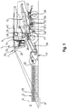
- An embodiment that is in the Figures 1 to 8 comprises a combine harvester 1 according to the invention, which is suitable for performing the method according to the invention.
- the combine harvester 1 comprises at its front end a cutting element 17, by means of which plants 30 of a stand 2 of plants can be cut.
- the cut plants 30 can then be conveyed by means of an inclined conveyor 24 in the direction of a threshing device 9 .
- the cut plants 30 can be processed by means of the threshing element 9, which comprises a threshing drum 10 and a threshing concave 11 , so that fruits can be detached from plant residues.
- the threshing drum 10 is operated in rotation about an associated axis of rotation, whereby the fruits are detached from the plant residues in cooperation with the threshing concave 11, which is arranged at a distance 16 from a circumferential surface of the threshing drum 10 .
- the threshing drum 10 and the concave 11 jointly delimit a guide gap 18 through which a crop layer 31 formed by the plants 30 can be guided.
- a large part of the detached fruit is deposited directly downward through recesses in the concave 11 onto a conveying device 41 and fed to a sieve device 29 by means of the conveying device 41 .
- Detached fruits that have not already been separated by the concave 11 are transferred together with the remaining plant residues by means of a turning drum 25 to a separating element 12 connected downstream of the threshing element 9 .
- the latter is formed by a rack shaker.
- a first coarse screening stage of the separating element 12 coarse plant residues are separated from the fruits and small plant residues, whereupon the mixture of small plant residues and the fruits is fed to the screening device 29 .
- this comprises an upper sieve 27 and a lower sieve 28, each of which has a plurality of sieve openings 13 have.
- the sieve openings 13 of the upper sieve 27 each have larger opening cross-sections 14 than the lower sieve 28, which is finer in comparison.
- the sieve device 29 interacts with a fan 15 , by means of which a directed air flow 37 can be generated.
- the task of the fan 15 is to separate the small plant residues, in particular chaff 32, from the fruits, which can be formed in particular by grains 33 , according to the principle of air separation.
- a crop flow which is ultimately fed to a grain tank 42 of the combine harvester 1 , consists to the greatest possible extent of fruits and is consequently as free as possible from plant residues.
- the upper sieve 27 and the lower sieve 28 each cooperate with an actuator 20 , by means of which lamellae 34 can be adjusted.
- the actuator 20 which can be formed , for example, by a linear motor, interacts with a sliding linkage that is connected to all of the slats 34 of the respective screen.
- the lamellae 34 can be pivoted together in this way about an associated joint 35 , so that a lamella angle 38 of the lamellae 34 changes in relation to a sieve plane of the respective sieve.
- the combine harvester according to the invention has a sensor device 7, which is formed here by a camera, at a front upper end of a driver's cab 43 .
- the sensor device 7 makes it possible to optically detect an area 8 in front of the combine harvester 1 .
- the front area 8 is arranged in front of the cutting element 17 , viewed in the direction of travel of the combine harvester 1 , a distance of the front area 8 from the cutting element 17 being approximately 10 m in the example shown.
- the sensor device 7 is connected here by means of a data connection 26 to a computing unit 19 which is arranged in the driver's cab 43 . By means of the computing unit 19 it is possible to process data that have been recorded by means of the sensor device 7 .
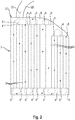
- the combine harvester 1 first drives over an access road 22 onto the field 21.
- a lane 23 of the combine harvester 1 is in Figure 2 illustrated by means of a dashed line.
- an area of the headland 6 has not been planted with plants 30 to be harvested, so that processing of an edge area of the field 21 for the purpose of creating the headland 6 can be dispensed with here. Consequently, the processing of the crop 2 can take place immediately, the combine harvester successively sweeping over a plurality of sections 3 running parallel to one another , which are here each formed by straight working tracks.
- the combine harvester 1 moves into the stand 2 at the beginning of the stand 4 and out of the stand 2 again at the end of the section 3 at an assigned end 5 of the stand.
- the combine harvester 1 then turns in the headland 6 and processes the next section 3 in the same way .
- the data recorded by means of the sensor device 7 are passed to the computing unit 19 and evaluated there.
- An interpretation of the image data recorded by means of the sensor device 7 which is carried out by means of the computing unit 19 , has the result that the end of the inventory 5 is recognized.
- the combine harvester 1 will soon reach the end of the crop 5 .
- the crop throughput will decrease, since the end of the stand 5 represents the boundary between the stand 2 and the headland 6 , whereby no further plants 30 are cut and fed to the threshing device 9 as a result of the movement out of the stand 2 .
- the effect can be added that a density of the plants 30 in an edge area of the stand 2 is typically lower than in a central area of the stand 2.
- a mass flow of harvested plants 30 that is to be processed by the combine harvester 1 already decreases when approaching end of inventory 5 , until it finally drops to zero after reaching the end of inventory 5 and the associated exit from inventory 2 .
- these effects can be taken into account in terms of control technology by changing at least one operating parameter of the combine harvester 1 according to the invention.
- a plurality of operating parameters are changed in order to take into account the changing crop throughput in the course of moving out of the crop 2 to the crop end 5 .
- the computing unit 19 is connected by means of a plurality of data connections 26 to various actuators 20 which interact with various working elements of the combine harvester 1 .
- a total of four operating parameters of the combine harvester 1 are changed at least temporarily as a result of the recognition of the end of the crop 5 or analogously to a start of the crop 4 .
- These are the operating parameters "distance 16 of the concave 11 from the threshing drum 10", "speed of the threshing drum 10", "speed of the fan 15” and "opening cross-sections 14 of the sieve openings 13".
- the reduction of the distance 16 between the threshing drum 10 and the threshing concave 11 of the threshing drum 10 helps to counteract this.
- the screening device 29 it is advantageous to reduce the opening cross-sections 14 of the openings 13 in the course of moving out of the stock 2 and also to reduce the speed of the fan 15 .
- the power of a fan motor 39 of the fan 15 is reduced. In this way, it is avoided that an increased discharge of grains 33 from the combine harvester 1 as a result of a smaller layer thickness 36 of the crop layer 31 takes place, while an undesirably high proportion of small components of the plant residues, in particular in Form of chaff 32, not carried out, but collected together with the fruit.
- the change in the operating parameters of the combine harvester 1 can be carried out in a planned manner in a particularly advantageous manner, this being carried out without recording the layer thickness 36 of the crop layer 31 .
- This has the particular advantage that it is not necessary to wait for the change in the layer thickness 36 until the operating parameters of the combine harvester 1 can actually be adapted.
- the change in the operating parameters is planned:
- the change in at least one of the operating parameters can then be carried out at the same time as the actual decrease in the crop throughput; the said acceptance does not have to be waited for before reactions are possible.
- changes in the operating parameters can already be made in advance of reaching the end of the crop 5 , whereby in particular the above-explained, continuously decreasing crop throughput as the crop is approached 5 can be taken into account.
- the work organs of the combine harvester 1 can be controlled in a targeted manner in such a way that the fruit losses are reduced to a minimum.
Landscapes
- Life Sciences & Earth Sciences (AREA)
- Environmental Sciences (AREA)
- Threshing Machine Elements (AREA)
Applications Claiming Priority (1)
| Application Number | Priority Date | Filing Date | Title |
|---|---|---|---|
| DE102019111089.0A DE102019111089A1 (de) | 2019-04-30 | 2019-04-30 | Verfahren zur Ernte eines auf einem Feld angeordneten Bestandes zu erntender Pflanzen wie Mähdrescher |
Publications (2)
| Publication Number | Publication Date |
|---|---|
| EP3732949A1 true EP3732949A1 (fr) | 2020-11-04 |
| EP3732949B1 EP3732949B1 (fr) | 2025-11-12 |
Family
ID=69156338
Family Applications (1)
| Application Number | Title | Priority Date | Filing Date |
|---|---|---|---|
| EP20150958.5A Active EP3732949B1 (fr) | 2019-04-30 | 2020-01-09 | Procédé de récolte d'un peuplement de plantes à récolter disposé dans un champ et moissonneuse-batteuse |
Country Status (2)
| Country | Link |
|---|---|
| EP (1) | EP3732949B1 (fr) |
| DE (1) | DE102019111089A1 (fr) |
Cited By (2)
| Publication number | Priority date | Publication date | Assignee | Title |
|---|---|---|---|---|
| EP4136956A1 (fr) * | 2021-08-17 | 2023-02-22 | CLAAS Selbstfahrende Erntemaschinen GmbH | Procédé de fonctionnement d'une machine de récolte automotrice et machine de récolte automotrice |
| CN119366356A (zh) * | 2024-12-30 | 2025-01-28 | 中国农业科学院草原研究所 | 基于物联网的饲草种子的高效低损联合收获方法及系统 |
Families Citing this family (2)
| Publication number | Priority date | Publication date | Assignee | Title |
|---|---|---|---|---|
| US10806079B2 (en) | 2018-02-26 | 2020-10-20 | Deere & Company | Automatic product harvesting method and control system |
| US11870973B2 (en) | 2021-07-27 | 2024-01-09 | Deere & Company | Camera calibration tool |
Citations (5)
| Publication number | Priority date | Publication date | Assignee | Title |
|---|---|---|---|---|
| DE102007055073A1 (de) | 2007-11-16 | 2009-05-20 | Claas Selbstfahrende Erntemaschinen Gmbh | Selbstfahrende landwirtschaftliche Erntemaschine |
| DE102013209197A1 (de) * | 2013-05-17 | 2014-11-20 | Deere & Company | Erntemaschine mit vorausschauender Vortriebsgeschwindigkeitsregelung |
| DE102014114717A1 (de) | 2014-10-10 | 2016-04-14 | Hartmut Kemmner | Vorrichtung zum Bearbeiten von Erntegut und Verfahren zum Steuern eines Erntegutflusses in der Vorrichtung |
| EP3259976A1 (fr) * | 2016-06-24 | 2017-12-27 | CLAAS Selbstfahrende Erntemaschinen GmbH | Engin agricole et procédé de fonctionnement d'un engin agricole |
| DE102016118651A1 (de) * | 2016-09-30 | 2018-04-05 | Claas Selbstfahrende Erntemaschinen Gmbh | Selbstfahrende landwirtschaftliche Arbeitsmaschine |
-
2019
- 2019-04-30 DE DE102019111089.0A patent/DE102019111089A1/de not_active Withdrawn
-
2020
- 2020-01-09 EP EP20150958.5A patent/EP3732949B1/fr active Active
Patent Citations (5)
| Publication number | Priority date | Publication date | Assignee | Title |
|---|---|---|---|---|
| DE102007055073A1 (de) | 2007-11-16 | 2009-05-20 | Claas Selbstfahrende Erntemaschinen Gmbh | Selbstfahrende landwirtschaftliche Erntemaschine |
| DE102013209197A1 (de) * | 2013-05-17 | 2014-11-20 | Deere & Company | Erntemaschine mit vorausschauender Vortriebsgeschwindigkeitsregelung |
| DE102014114717A1 (de) | 2014-10-10 | 2016-04-14 | Hartmut Kemmner | Vorrichtung zum Bearbeiten von Erntegut und Verfahren zum Steuern eines Erntegutflusses in der Vorrichtung |
| EP3259976A1 (fr) * | 2016-06-24 | 2017-12-27 | CLAAS Selbstfahrende Erntemaschinen GmbH | Engin agricole et procédé de fonctionnement d'un engin agricole |
| DE102016118651A1 (de) * | 2016-09-30 | 2018-04-05 | Claas Selbstfahrende Erntemaschinen Gmbh | Selbstfahrende landwirtschaftliche Arbeitsmaschine |
Cited By (3)
| Publication number | Priority date | Publication date | Assignee | Title |
|---|---|---|---|---|
| EP4136956A1 (fr) * | 2021-08-17 | 2023-02-22 | CLAAS Selbstfahrende Erntemaschinen GmbH | Procédé de fonctionnement d'une machine de récolte automotrice et machine de récolte automotrice |
| US12490670B2 (en) | 2021-08-17 | 2025-12-09 | Claas Selbstfahrende Emtemaschinen Gmbh | Self-propelled agricultural harvester and method for operating a self-propelled agricultural harvester |
| CN119366356A (zh) * | 2024-12-30 | 2025-01-28 | 中国农业科学院草原研究所 | 基于物联网的饲草种子的高效低损联合收获方法及系统 |
Also Published As
| Publication number | Publication date |
|---|---|
| DE102019111089A1 (de) | 2020-11-05 |
| EP3732949B1 (fr) | 2025-11-12 |
Similar Documents
| Publication | Publication Date | Title |
|---|---|---|
| EP3533314B1 (fr) | Moissonneuse automotrice et son procédé de fonctionnement | |
| EP3403485B1 (fr) | Dispositif d'auto-apprentissage, prenant en considération les entrées de correction destiné au contrôle automatique d'un paramètre de travail d'un dispositif de transport de produit de la récolte et/ou de traitement | |
| EP3459338B1 (fr) | Machine de travail | |
| EP3732949B1 (fr) | Procédé de récolte d'un peuplement de plantes à récolter disposé dans un champ et moissonneuse-batteuse | |
| EP3180974B1 (fr) | Procédé de fonctionnement d'une moissonneuse-batteuse | |
| EP2591664B1 (fr) | Crible pour une installation de nettoyage d'une moissonneuse-batteuse | |
| EP1731017B1 (fr) | Méthode de commande d'une moissoneuse | |
| EP3494771B1 (fr) | Dispositif de hauteur de coupe automatique | |
| EP1769667B1 (fr) | Moissoneuse automatrice and méthode de commande pour celle-ci | |
| DE102010017687A1 (de) | Verfahren zur Einstellung zumindest eines Arbeitsorganes einer selbstfahrenden Erntemaschine | |
| EP3424292B1 (fr) | Procédé d'analyse de l'état de fonctionnement d'une barre de coupe et barre de coupe | |
| DE102007046678A1 (de) | Landwirtschaftliches Arbeitsfahrzeug | |
| DE102005038553A1 (de) | Verfahren zum Überladen von Erntegut | |
| WO2003005803A1 (fr) | Dispositif de distribution conçu pour des produits haches issus d'une recolteuse | |
| DE102005014278A1 (de) | Verfahren zur Ermittlung eines Ziel-Einstellwerts | |
| EP2550851A1 (fr) | Dispositif de nettoyage pour une moissonneuse-batteuse | |
| EP1790207B1 (fr) | Moissonneuse | |
| BE1022629B1 (de) | Verfahren und Steuerungssystem zum Betreiben eines Feldhäckslers sowie Feldhäcksler | |
| EP3797575B1 (fr) | Moissonneuse-batteuse avec système d'assistance au conducteur | |
| DE102021121296A1 (de) | Verfahren für den Betrieb einer selbstfahrenden landwirtschaftlichen Erntemaschine sowie selbstfahrende landwirtschaftliche Erntemaschine | |
| EP4252519B1 (fr) | Moissonneuse agricole et procédé de commande d'une moissonneuse agricole | |
| EP4209123B1 (fr) | Contre-batteur pour moissonneuse-batteuse | |
| DE102019107822A1 (de) | Axialabscheider für einen Mähdrescher | |
| EP3797577B1 (fr) | Moissonneuse-batteuse pourvue de capteur de grains restants | |
| EP1479280B1 (fr) | Dispositif et procédé de separation d'un flux de produits de récolte |
Legal Events
| Date | Code | Title | Description |
|---|---|---|---|
| PUAI | Public reference made under article 153(3) epc to a published international application that has entered the european phase |
Free format text: ORIGINAL CODE: 0009012 |
|
| STAA | Information on the status of an ep patent application or granted ep patent |
Free format text: STATUS: THE APPLICATION HAS BEEN PUBLISHED |
|
| AK | Designated contracting states |
Kind code of ref document: A1 Designated state(s): AL AT BE BG CH CY CZ DE DK EE ES FI FR GB GR HR HU IE IS IT LI LT LU LV MC MK MT NL NO PL PT RO RS SE SI SK SM TR |
|
| AX | Request for extension of the european patent |
Extension state: BA ME |
|
| STAA | Information on the status of an ep patent application or granted ep patent |
Free format text: STATUS: REQUEST FOR EXAMINATION WAS MADE |
|
| 17P | Request for examination filed |
Effective date: 20210504 |
|
| RBV | Designated contracting states (corrected) |
Designated state(s): AL AT BE BG CH CY CZ DE DK EE ES FI FR GB GR HR HU IE IS IT LI LT LU LV MC MK MT NL NO PL PT RO RS SE SI SK SM TR |
|
| STAA | Information on the status of an ep patent application or granted ep patent |
Free format text: STATUS: EXAMINATION IS IN PROGRESS |
|
| 17Q | First examination report despatched |
Effective date: 20220628 |
|
| P01 | Opt-out of the competence of the unified patent court (upc) registered |
Effective date: 20230516 |
|
| GRAP | Despatch of communication of intention to grant a patent |
Free format text: ORIGINAL CODE: EPIDOSNIGR1 |
|
| STAA | Information on the status of an ep patent application or granted ep patent |
Free format text: STATUS: GRANT OF PATENT IS INTENDED |
|
| INTG | Intention to grant announced |
Effective date: 20250611 |
|
| GRAS | Grant fee paid |
Free format text: ORIGINAL CODE: EPIDOSNIGR3 |
|
| GRAA | (expected) grant |
Free format text: ORIGINAL CODE: 0009210 |
|
| STAA | Information on the status of an ep patent application or granted ep patent |
Free format text: STATUS: THE PATENT HAS BEEN GRANTED |
|
| AK | Designated contracting states |
Kind code of ref document: B1 Designated state(s): AL AT BE BG CH CY CZ DE DK EE ES FI FR GB GR HR HU IE IS IT LI LT LU LV MC MK MT NL NO PL PT RO RS SE SI SK SM TR |
|
| REG | Reference to a national code |
Ref country code: CH Ref legal event code: F10 Free format text: ST27 STATUS EVENT CODE: U-0-0-F10-F00 (AS PROVIDED BY THE NATIONAL OFFICE) Effective date: 20251112 Ref country code: GB Ref legal event code: FG4D Free format text: NOT ENGLISH |
|
| REG | Reference to a national code |
Ref country code: DE Ref legal event code: R096 Ref document number: 502020012208 Country of ref document: DE |
|
| REG | Reference to a national code |
Ref country code: IE Ref legal event code: FG4D Free format text: LANGUAGE OF EP DOCUMENT: GERMAN |
|
| REG | Reference to a national code |
Ref country code: NL Ref legal event code: MP Effective date: 20251112 |
|
| PG25 | Lapsed in a contracting state [announced via postgrant information from national office to epo] |
Ref country code: ES Free format text: LAPSE BECAUSE OF FAILURE TO SUBMIT A TRANSLATION OF THE DESCRIPTION OR TO PAY THE FEE WITHIN THE PRESCRIBED TIME-LIMIT Effective date: 20251112 |
|
| REG | Reference to a national code |
Ref country code: LT Ref legal event code: MG9D |
|
| PG25 | Lapsed in a contracting state [announced via postgrant information from national office to epo] |
Ref country code: NO Free format text: LAPSE BECAUSE OF FAILURE TO SUBMIT A TRANSLATION OF THE DESCRIPTION OR TO PAY THE FEE WITHIN THE PRESCRIBED TIME-LIMIT Effective date: 20260212 |
|
| PGFP | Annual fee paid to national office [announced via postgrant information from national office to epo] |
Ref country code: DE Payment date: 20260121 Year of fee payment: 7 |
|
| PG25 | Lapsed in a contracting state [announced via postgrant information from national office to epo] |
Ref country code: FI Free format text: LAPSE BECAUSE OF FAILURE TO SUBMIT A TRANSLATION OF THE DESCRIPTION OR TO PAY THE FEE WITHIN THE PRESCRIBED TIME-LIMIT Effective date: 20251112 Ref country code: HR Free format text: LAPSE BECAUSE OF FAILURE TO SUBMIT A TRANSLATION OF THE DESCRIPTION OR TO PAY THE FEE WITHIN THE PRESCRIBED TIME-LIMIT Effective date: 20251112 |
|
| PGFP | Annual fee paid to national office [announced via postgrant information from national office to epo] |
Ref country code: BE Payment date: 20260121 Year of fee payment: 7 |
|
| PG25 | Lapsed in a contracting state [announced via postgrant information from national office to epo] |
Ref country code: NL Free format text: LAPSE BECAUSE OF FAILURE TO SUBMIT A TRANSLATION OF THE DESCRIPTION OR TO PAY THE FEE WITHIN THE PRESCRIBED TIME-LIMIT Effective date: 20251112 |
|
| PG25 | Lapsed in a contracting state [announced via postgrant information from national office to epo] |
Ref country code: RS Free format text: LAPSE BECAUSE OF FAILURE TO SUBMIT A TRANSLATION OF THE DESCRIPTION OR TO PAY THE FEE WITHIN THE PRESCRIBED TIME-LIMIT Effective date: 20260212 |
|
| PG25 | Lapsed in a contracting state [announced via postgrant information from national office to epo] |
Ref country code: IS Free format text: LAPSE BECAUSE OF FAILURE TO SUBMIT A TRANSLATION OF THE DESCRIPTION OR TO PAY THE FEE WITHIN THE PRESCRIBED TIME-LIMIT Effective date: 20260312 |
|
| PG25 | Lapsed in a contracting state [announced via postgrant information from national office to epo] |
Ref country code: PT Free format text: LAPSE BECAUSE OF FAILURE TO SUBMIT A TRANSLATION OF THE DESCRIPTION OR TO PAY THE FEE WITHIN THE PRESCRIBED TIME-LIMIT Effective date: 20260312 |
|
| PG25 | Lapsed in a contracting state [announced via postgrant information from national office to epo] |
Ref country code: PL Free format text: LAPSE BECAUSE OF FAILURE TO SUBMIT A TRANSLATION OF THE DESCRIPTION OR TO PAY THE FEE WITHIN THE PRESCRIBED TIME-LIMIT Effective date: 20251112 |
|
| PG25 | Lapsed in a contracting state [announced via postgrant information from national office to epo] |
Ref country code: LV Free format text: LAPSE BECAUSE OF FAILURE TO SUBMIT A TRANSLATION OF THE DESCRIPTION OR TO PAY THE FEE WITHIN THE PRESCRIBED TIME-LIMIT Effective date: 20251112 |