EP3733108B1 - Chirurgischer roboteranschluss - Google Patents
Chirurgischer roboteranschluss Download PDFInfo
- Publication number
- EP3733108B1 EP3733108B1 EP18893614.0A EP18893614A EP3733108B1 EP 3733108 B1 EP3733108 B1 EP 3733108B1 EP 18893614 A EP18893614 A EP 18893614A EP 3733108 B1 EP3733108 B1 EP 3733108B1
- Authority
- EP
- European Patent Office
- Prior art keywords
- axis
- joint
- arm
- base
- setup
- Prior art date
- Legal status (The legal status is an assumption and is not a legal conclusion. Google has not performed a legal analysis and makes no representation as to the accuracy of the status listed.)
- Active
Links
Images




Classifications
-
- A—HUMAN NECESSITIES
- A61—MEDICAL OR VETERINARY SCIENCE; HYGIENE
- A61B—DIAGNOSIS; SURGERY; IDENTIFICATION
- A61B90/00—Instruments, implements or accessories specially adapted for surgery or diagnosis and not covered by any of the groups A61B1/00 - A61B50/00, e.g. for luxation treatment or for protecting wound edges
- A61B90/50—Supports for surgical instruments, e.g. articulated arms
-
- A—HUMAN NECESSITIES
- A61—MEDICAL OR VETERINARY SCIENCE; HYGIENE
- A61B—DIAGNOSIS; SURGERY; IDENTIFICATION
- A61B34/00—Computer-aided surgery; Manipulators or robots specially adapted for use in surgery
- A61B34/30—Surgical robots
- A61B34/37—Leader-follower robots
-
- A—HUMAN NECESSITIES
- A61—MEDICAL OR VETERINARY SCIENCE; HYGIENE
- A61B—DIAGNOSIS; SURGERY; IDENTIFICATION
- A61B17/00—Surgical instruments, devices or methods
- A61B17/00234—Surgical instruments, devices or methods for minimally invasive surgery
-
- A—HUMAN NECESSITIES
- A61—MEDICAL OR VETERINARY SCIENCE; HYGIENE
- A61B—DIAGNOSIS; SURGERY; IDENTIFICATION
- A61B34/00—Computer-aided surgery; Manipulators or robots specially adapted for use in surgery
- A61B34/70—Manipulators specially adapted for use in surgery
-
- B—PERFORMING OPERATIONS; TRANSPORTING
- B25—HAND TOOLS; PORTABLE POWER-DRIVEN TOOLS; MANIPULATORS
- B25J—MANIPULATORS; CHAMBERS PROVIDED WITH MANIPULATION DEVICES
- B25J9/00—Program-controlled manipulators
- B25J9/0084—Program-controlled manipulators comprising a plurality of manipulators
- B25J9/0087—Dual arms
-
- A—HUMAN NECESSITIES
- A61—MEDICAL OR VETERINARY SCIENCE; HYGIENE
- A61B—DIAGNOSIS; SURGERY; IDENTIFICATION
- A61B90/00—Instruments, implements or accessories specially adapted for surgery or diagnosis and not covered by any of the groups A61B1/00 - A61B50/00, e.g. for luxation treatment or for protecting wound edges
- A61B90/06—Measuring instruments not otherwise provided for
- A61B2090/067—Measuring instruments not otherwise provided for for measuring angles
-
- A—HUMAN NECESSITIES
- A61—MEDICAL OR VETERINARY SCIENCE; HYGIENE
- A61B—DIAGNOSIS; SURGERY; IDENTIFICATION
- A61B90/00—Instruments, implements or accessories specially adapted for surgery or diagnosis and not covered by any of the groups A61B1/00 - A61B50/00, e.g. for luxation treatment or for protecting wound edges
- A61B90/50—Supports for surgical instruments, e.g. articulated arms
- A61B2090/506—Supports for surgical instruments, e.g. articulated arms using a parallelogram linkage, e.g. panthograph
Definitions
- the present application relates to the field of medical devices and, more specifically, to a surgical robot terminal.
- US 2017/079722 A1 discloses methods and systems for registering a manipulator assembly and independently positionable surgical table, wherein the methods include reading a fiducial marker on the surgical table with a sensor associated with the manipulator assembly and localizing the manipulator assembly and surgical table with respect to a common reference frame, wherein the methods further include translating a 3D configuration of the surgical table to a 2D frame of reference so as to estimate a 3D pose of the surgical table relative the manipulator assembly for use in coordinating movements therebetween.
- CN 107 374 736 A discloses a surgical cart comprising a standing column, wherein vertical guide rails are arranged on the outer walls of the standing column and a slider is slidably arranged on each vertical guide rail, wherein a base for mounting a mechanical arm is fixedly arranged on each slider, and limit devices for controlling the corresponding base to move in stroke limit are respectively arranged at the top and the bottom of each outer wall of the standing column.
- CN 106 236 276 A discloses a surgical robot system comprising robotic arms, a base, a support connected to the base, and a suspension structure connected to the support, wherein the suspension structure is connected to the robotic arms.
- WO 2006/079108 A1 discloses a robotic surgical system comprising a manipulator support assembly, wherein the manipulator support assembly comprises an orienting platform and a plurality of configurable set-up joint arms couplable to the orienting platform.
- US 2004/261179 A1 discloses a linkage structure rotatably connected to the ceiling.
- CN 106 618 736 A discloses a robotic arm comprising a support structure that functions as a support for the robotic arm.
- a terminal a surgical robot terminal comprising:
- each of the arm supports has a proximal end coupled to the support end of the vertical assembly and a distal end coupled to at least one of the plurality of setup arms.
- the support mechanism further comprises a primary arm support having a proximal end rotatably coupled to the support end of the vertical assembly, and wherein each of the at least two arm supports has a proximal end rotatably coupled to a distal end of the primary arm support and a distal end coupled to at least one of the plurality of setup arms.
- each of the plurality of setup arms comprises a first rotary joint, a first horizontal translational joint, a swinging joint and a second rotary joint, which are sequentially coupled together successively,
- the swinging joint comprises a first parallelogram structure formed by articulated links including a first proximal link and a first distal link parallel to the first proximal link, the first proximal link extending parallel to the axis of rotation of the first rotary joint, the first distal link being coupled to the second rotary joint and extending parallel to the axis of rotation of the second rotary joint.
- each of the plurality of setup arms comprises a connecting rod rotatably coupled to both the swinging joint and the second rotary joint, a measurement component for measuring a swing angle of the swinging joint and a motor for driving the second rotary joint to swing relative to the connecting rod, the measurement component being communicatively coupled to the motor that is configured to drive the second rotary joint to swing in accordance with the swing angle of the swinging joint received from the measurement component so that the axis of rotation of the second rotary joint is maintained parallel to the axis of rotation of the first rotary joint.
- each of the plurality of setup arms further comprises a second horizontal translational joint having a proximal end coupled to the support mechanism and a distal end coupled to the first rotary joint, the second horizontal translational joint having an axis of translation that is perpendicular to the axis of rotation of the first rotary joint.
- each of the plurality of setup arms comprises a first horizontal translational joint, a first rotary joint, a swinging joint and a second rotary joint, which are sequentially coupled together successively,
- each of the plurality of tool arms has three or more degrees of freedom, and thus is able to drive the surgical instrument to at least swing left and right, pivot front and back and move up and down with respect to the remote center of motion.
- each of the plurality of tool arms comprises a base joint, a telescopic joint, and a second parallelogram structure formed by articulated links,
- each of the plurality of tool arms has two or more degrees of freedom, and thus is able to drive the surgical instrument to at least swing left and right and pivot front and back with respect to the remote center of motion.
- each of the plurality of tool arms comprises a base joint and a third parallelogram structure formed by articulated links
- the terminal further comprises a console for controlling operation of the base, the vertical assembly and/or the robotic arms.
- the surgical robot terminal includes a moveable base and a support mechanism disposed between the support end of the vertical assembly and the proximal ends of the setup arms, and the horizontal movability of the base allows the robotic arms (especially their setup arms) to move in an expanded range and enables the terminal to reach any desired position without the use of any additional component supported on a ceiling of an operating room.
- This allows a simplified overall structure and a reduced mass of the terminal, making it more consistent with the demand for lightweight, structurally simpler medical robots.
- the employment of the support mechanism not only further expands the robotic arms' movement range but can effectively avoid interference between the robotic arms when they are moving, thus enhancing the terminal's adjustability and operating reliability.
- the movability of the base in combination with the vertical translation of the vertical translational joint in the vertical assembly further allows the remote center of motion (RCM) of each robotic arm and the surgical instrument mounted thereon to more easily access a surgical site in a patient, and the structurally simpler terminal can therefore place the robotic arm to a position more suitable for performing an operation on the surgical site, thereby facilitating the surgical operation.
- RCM remote center of motion
- Providing the base with both the drive and guide wheels can decouple speed control from direction control, resulting in both enhanced maneuverability and maneuver accuracy, which are in particular conducive to the overall movement of large equipment such as the surgical robot terminal.
- proximal end of an object is meant to refer to an end thereof located farther away from a remote center (RC), also called a remote center of motion (RCM), and closer to a vertical assembly, while a “distal end” or “terminal end” thereof is meant to refer to an end closer to the RCM and farther away from the vertical assembly.
- RC remote center
- terminal end thereof is meant to refer to an end closer to the RCM and farther away from the vertical assembly.
- the terminal includes a movable base 1, a vertical assembly 2, a support mechanism (not shown in Fig. 1 ) and multiple robotic arms 3.
- the vertical assembly has a base end 203 secured to the base 1 and a support end 202 located above the base 1 and rotatably coupled to the support mechanism.
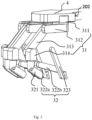
- Each robotic arm 3 includes a setup arm 31 and a tool arm 32. A proximal end of the setup arm 31 is coupled to the support mechanism, and a distal end thereof is coupled to the tool arm 32. A distal end of the tool arm 32 is coupled to a surgical instrument.
- the tool arm 32 is configured to drive the surgical instrument to pivot about a remote center (RC) of motion, while the setup arm 31 is adapted to adjust a spatial position of the RCM.
- the vertical assembly 2 includes a vertical translational joint 21 for adjusting a height of the RCM relative to the base 1.
- the support mechanism may include at least two arm supports, to each of which one or more of the robotic arms 3 may be attached, in order to avoid interference between the robotic arms 3.
- the base 1 may be provided at the bottom with at least two wheel sets each including a drive wheel and a guide wheel respectively configured for movement speed control and movement direction control, thereby facilitating movement of the base 1. A more detailed description of the support mechanism and the wheel sets will be set forth below.
- One of the primary objectives of the surgical robot terminal is to allow an arrival of the RCM of the robotic arm 3 at a desired position suitable for the surgical instrument detachably coupled thereto to insert into a patient through an incision made around the RCM to arrive at a target surgical site.
- the adjustment and tool arms are required to minimize their mutual interference before and during use in a surgical operation.
- the base 1 is moveable in all directions, while the vertical assembly 2 can move up and down. The combination of base 1 and the vertical assembly 2 allows each robotic arm 3 to more easily approach the patient. By providing the support mechanism, interference between the multiple robotic arms 3 can be avoided, resulting in improved adjustment capabilities of the setup arms.
- the setup arm 31 is capable of performing spatial movement, so when the surgical robot terminal is near the patient, the setup arm 31 can be adjusted to cause an arrival of the RC at a desired position suitable for the surgical instrument to arrive at a surgical site in the patient, and the surgical instrument can be subsequently driven by the tool arm 32 to pivot about the RC so as to accomplish a particular surgical operation.
- the vertical assembly 2 may generally resemble the inverted letter "L".
- the vertical assembly 2 may include a vertical translational joint 21, a horizontal beam and a vertical column fixedly connected to a proximal end of the horizontal beam.
- the distal end of the horizontal beam serves as the support end 202.
- the support mechanism is rotatably coupled to the support end 202 with a rotation axis extending parallel to the vertical column and perpendicular to a horizontal plane.
- the vertical translational joint 21 is arranged on the vertical column (corresponding to a longer side of the L-like shape) and configured to vertically adjust the robotic arm 3 so as to change the height of the RC relative to the base 1.
- the base 1 in order to impart movability to the base 1, in the present embodiment, the base 1 essentially includes at least two wheel sets 11 each including a drive wheel 111 and a guide wheel 112, the guide wheel 112 configured for movement direction control, the drive wheel 111 configured for movement speed control.
- the at least two wheel sets 11 are configured to cooperate to displace the base 1 so as to adjusts a working position of each surgical instrument (relative to the patient).
- the base 1 preferably includes three wheel sets 11, which are arranged into a triangular pattern and motor-driven to enable movement of the base 1. With the adjustability of the three guide wheels 112 and movability of the three drive wheels 111, the surgical robot terminal can overall move along a certain path to approach the patient.
- the base 1 Since the base 1 is able to move freely, it can approach the patient at a suitable position compatible with conditions of the patient, and the RC approaches the patient simultaneously with the approaching of the surgical robot. This greatly simplifies the structure of the support end 202 of the vertical assembly 2 and hence overall structure of the surgical robot terminal while reducing the total mass of the surgical robot terminal, making it more consistent with the demand for lightweight, structurally simpler medical robots.
- the robotic arms 3 are oriented away from the vertical assembly 2 (i.e., their terminal ends of the robotic arms 3 extend outwardly).
- the orientation of each robotic arm 3 is determined by a combination of an angle of rotation and connection mode of the setup arm 31 and that of the tool arm 32.
- the setup arms 31 and tool arms 32 are rotatably coupled to each other at an angular difference adaptable as required by the surgical operation. That is, the orientation of the robotic arm 3 can be modified as per the actual surgical needs.
- each setup arm 31 includes a first rotary joint 311, a first horizontal translational joint 312, a swinging joint 313 and a second rotary joint 314, which are sequentially connected together in this order, the first horizontal translational joint 312 having an axis of translation (i.e., a movement trajectory or a telescopic direction thereof, or a track in case of the joint 312 being implemented as a slider-track structure) that is perpendicular to an axis of rotation of the first rotary joint 311, the swinging joint 313 having an axis of rotation that is perpendicular to both the axis of translation of the first horizontal translational joint 312 and an axis of rotation of the first rotary joint 311, the second rotary joint 314 having an axis of rotation oriented parallel to the axis of rotation of the first rotary joint 311.
- the first horizontal translational joint 312 having an axis of translation (i.e., a movement trajectory or a telescopic direction thereof, or a track in case of the joint
- the first rotary joint 311 couples the setup arm 31 to the support mechanism, while the second rotary joint 314 couples the setup arm 31 to the tool arm 32.
- the first rotary joint 311 is able to drive the whole robotic arm 3 to rotate about the axis of rotation of the first rotary joint 311, and the first horizontal translational joint 312 can drive the tool arm 32 to translate horizontally.
- the swinging joint 313 is configured to swing so as to drive the tool arm 32 to move within a vertical plane.
- the first and second rotary joints 311, 314 are redundant to each other and configured to enable finer adjustments. These four joints of the setup arm 31 can work together to allow any change of the RC in spatial position.
- the setup arm further includes a connecting rod, a measurement component and a motor communicatively coupled to the measurement component.
- a proximal end of the connecting rod is coupled to the swinging joint 313, and a distal end thereof is rotatably coupled to the second rotary joint 314.
- the measurement component is configured to measure a swing angle of the swinging joint 313 in real time.
- the motor is configured to cause the second rotary joint 314 to rotate relative to the connecting rod in accordance with the swing angle of the swinging joint 313 so as to always maintain the axis of rotation of the second rotary joint 314 parallel to that of the first rotary joint 311.
- the swinging joint 313 includes a first parallelogram structure formed by four links articulated together, including a proximal link maintained parallel to the axis of rotation of the first rotary joint 311 and a distal link (that is parallel to the proximal link) that is coupled to the second rotary joint 314 and maintained parallel to the axis of rotation of the second rotary joint 314. In this way, the axis of rotation of the second rotary joint 314 is always maintained parallel to that of the first rotary joint 311.
- the setup arm 31 further includes a second horizontal translational joint having a proximal end coupled to the support mechanism and a distal end coupled to the first rotary joint 311. Moreover, the second horizontal translational joint has an axis of translation that is perpendicular to the axis of rotation of the first rotary joint 311. In this way, the setup arm 31 has an effectively widened horizontal movement range.
- each setup arm includes a first horizontal translational joint 312, a first rotary joint 311, a swinging joint 313 and a second rotary joint 314, which are sequentially connected together in this order, the first horizontal translational joint 312 having an axis of translation perpendicular to an axis of rotation of the first rotary joint 311, the swinging joint 313 having an axis of rotation perpendicular to the axis of translation of the first horizontal translational joint 312 and perpendicular to the axis of rotation of the first rotary joint 311, the second rotary joint 314 having an axis of rotation oriented parallel to the axis of rotation of the first rotary joint 311.
- the first horizontal translational joint 312 couples the setup arm 31 to the support mechanism
- the second rotary joint 314 couples the setup arm 31 to the tool arm 32. This arrangement allows full utilization of a space around the support end 202 of the vertical assembly 2.
- the tool arm 32 is an RC mechanism capable of causing the surgical instrument coupled thereto to pivot about an RC.
- the tool arm 32 may have multiple degrees of freedom, such as two degrees of freedom (in this case, the tool arm 32 is able to drive the surgical instrument swing about the RC in both left-and-right and front-and-back directions), three degrees of freedom (in this case, the tool arm 32 is able to drive the surgical instrument to swing about the RC in both left-and-right and front-and-back directions and move up and down).
- the tool arm 32 has three degrees of freedom so as to be able to drive the surgical instrument to swing about a first axis "a”, pivot about a second axis "c” and translate along an axis of translation "b”, and the RC is defined at the intersection of the first axis "a", axis of translation "b” and second axis "c" (the three axes are indicated by dashed lines in the figure).
- the tool arm 32 includes a base joint 321, a second parallelogram structure and a telescopic joint 323.
- the base joint 321 is configured to rotate about the first axis "a” so as to cause the surgical instrument to swing about the first axis "a”.
- a proximal end of the base joint 321 is coupled to the setup arm 31, and a distal end thereof is coupled to the second parallelogram structure.
- the second parallelogram structure is rotatable and formed by articulated links, including a proximal link and a distal link parallel to the proximal link.
- a terminal end of the second parallelogram structure is coupled to the surgical instrument through the telescopic joint 323, and the surgical instrument is configured such that an axis thereof is parallel to the distal link.
- the second parallelogram structure is able to drive the surgical instrument to pivot about the second axis.
- the second parallelogram structure includes a first parallelogram sub-structure 322a and a second parallelogram sub-structure 322b connected thereto.
- the second parallelogram structure forms a double-parallelogram structure for driving the surgical instrument to rotate about the second axis "c".
- the first parallelogram sub-structure 322a includes a first proximal link and a first distal link (both not shown) parallel to the first proximal link.
- the second parallelogram sub-structure 322b includes a second proximal link and a second distal link (both not shown) parallel thereto. The first distal link may overlap with the second proximal link or the second distal link.
- the second parallelogram sub-structure 322b has a distal end coupled to the telescopic joint 323, which defines the axis of translation "b" that is parallel to an axis of the second distal link in the second parallelogram sub-structure 322b and extends through the RC.
- the telescopic joint 323 is detachably coupled to the surgical instrument so as to allow the surgical instrument to translate along the axis of translation "b".
- the tool arm 32 may have only two degrees of freedom so as to be able to drive the surgical instrument to swing about the first axis "a” and pivot about the second axis "c", with the RC being defined at the intersection of the first and second axes "a", "c".
- the tool arm 32 includes a base joint 321 and a third parallelogram structure, which is rotatable and formed by articulated links, including a proximal link and a distal link parallel to the proximal link.
- a terminal end of the third parallelogram structure is detachably coupled to the surgical instrument, and the axis of the surgical instrument is parallel to an axis of the distal link in the third parallelogram structure and extends through the RC.
- the tool arm may adopt another structure for driving the surgical instrument to swing about the RC, such as a structure incorporating a base joint and a slider-arcuate track structure coupled to the base joint.
- the setup arm 31 causes the RC of the tool arm 32 to approach a target surgical site in the patient, thereby facilitating the implementation of a more accurate surgical operation.
- all the joints of the setup arm 31 are locked so that the RC is fixed in position, and the surgical instrument detachably coupled to the tool arm 32 is configured to insert into the patient via an incision around the RC to arrive at the target surgical site.
- the surgical instrument can be driven by the tool arm 32 to swing and pivot within a conical working space with an apex located at the RC.
- adjusting the RC's position through the setup arm 31 allows the surgical instrument mounted on the tool arm 32 to arrive at the target surgical site, and adjusting the individual joints of the tool arm 32 enables the surgical instrument to move within a RC-defined space suitable for a desired particular surgical operation.
- the surgical robot terminal's degrees of freedom of adjustment include: in-plane translational degrees of freedom 101, 102 of the base 1 (which together allow the base 1 to move along a curved movement trajectory 103); a vertical translational degree of freedom 201 of the vertical assembly 2; four degrees of freedom of each setup arm 31, which are respectively a first rotational degree of freedom 301, a first horizontal translational degree of freedom 302, a swinging degree of freedom 303 and a second rotational degree of freedom 304; and a third rotational degree of freedom 401 of the support mechanism.
- the in-plane translational degrees of freedom 101, 102 are enabled by the guide and drive wheels 111, 112 of the base 1.
- the terminal may move around the dashed line as a result of both traveling of the base 1 and upward or downward movement of the vertical assembly 2, so that a corresponding one of the robotic arms 3 can be located at a position closer to the RC and suitable for the robotic arm 3 to arrive at a target surgical site.
- the four degrees of freedom impart spatial movability to each setup arm 31 and enable the surgical instrument mounted on a terminal end of the corresponding tool arm 32 to more accurately get close to a desired RC.
- the third rotational degree of freedom 401 of the support mechanism allows each setup arm 31 to move in a wider range without interference between the setup arms 31 and even between the robotic arms 3.
- each joint in the surgical robot terminal may be provided with respective brakes configured to control locking or unlocking of these joints.
- each brake may be in a released state when it is energized by electricity, in which the corresponding joint can move normally, or in a locked state when it is not energized by electricity, in which the joint remains stationary at a particular orientation.
- each joint may be provided with a motor for allowing its initiative adjustment such as acceleration or deceleration.
- each joint in the surgical robot terminal may be provided with at least one sensor for sensing status information of the joint, from which a spatial position and orientation of an end effector (not shown) of the corresponding surgical instrument can be derived.
- the surgical robot terminal may include a console for controlling operation of the base 1, the vertical assembly 2 and/or the robotic arms 3.
- the console is communicatively coupled to the aforementioned sensors, brakes and motors and configured to obtain the status information about the joints from the sensors and lock or unlock the individual joints by means of the respective brakes.
- the console is also configured to facilitate movement of the individual joints by controlling torque outputs of the respective motors.
- the support mechanism includes at least two arm supports, each having an upper end coupled to the support end 202 of the vertical assembly 2 and a lower end coupled to at least one setup arm 31.
- each arm support is rotatably coupled to at least one setup arm 31.
- the arm support can rotate to change a spatial position of the setup arm 31, thereby expanding an adjustment range of the setup arm 31.
- the support mechanism can adjust spatial positions of the robotic arms 3 before a surgical operation is performed. This can greatly reduce interference between the robotic arms 3 during surgery, thus enhancing the adjustability of the setup arm 31.
- the support mechanism includes two arm supports, i.e., a first arm support 41a and a second arm support 41b.
- each of the first and second arm supports 41a, 41b is coupled to both the first rotary joints 311 of two setup arms 31.
- the two setup arms 31 coupled to the first arm support 41a are located on opposite sides thereof, and the two setup arms 31 coupled to the second arm support 41b are likewise located on opposite sides thereof.
- a second horizontal translational joint may be additionally provided between the setup arms 31 and the support mechanism (incorporating the first and second arm supports 41a, 41b).
- each setup arm 31 is coupled at the first rotary joint 311 to the support mechanism (i.e., to the first sus-pension disc 41a or the second arm support 41b) via the second horizontal translational joint. This can effectively expand the movement range of the robotic arms 3.
- the second horizontal translational joint may be provided between the first arm support 41a or second arm support 41b and the corresponding setup arms 31.
- each of the setup arms 31 is coupled at the first rotary joint 311 to the first arm support 41a or second arm support 41b via the second horizontal translational joint, and the aforementioned first horizontal translational joint 312 is omitted, with the swinging joint 313 coupled to the first rotary joint 311. This enables full utilization of the space around the support end 202 of the vertical assembly 2.
- the surgical robot terminal includes one primary arm support 42 and at least two secondary arm supports 43, the primary arm support 42 having an upper end rotatably coupled to the support end 202 of the vertical assembly 2, each of the at least two secondary arm supports 43 being rotatably coupled to a lower end of the primary arm support 42 and having a lower end coupled to corresponding setup arms 31.
- the primary arm support 42 can rotate to change spatial positions of the secondary arm supports 43, and in turn, each of the secondary arm supports 43 can rotate to change spatial positions of the setup arms 31 coupled thereto.
- the number of the primary arm support 42 is one and the number of the secondary arm supports 43 is two
- each of the two secondary arm supports 43 is rotatably coupled at the upper end thereof to the primary arm support 42 so that the secondary arm supports 43 can rotate relative to the primary arm support 42.
- the primary arm support 42 can adjust the position of the secondary arm supports 43, which can in turn adjust the positions of the setup arms 31 that are coupled to them.
- Each of the secondary arm supports 43 is coupled at the lower end thereof to two setup arms 31 in such a manner that the setup arms 31 are located at opposing sides of a corresponding secondary arm support 43.
- the secondary arm support 43 spaces the two setup arms 31 apart from each other. This can avoid interference between the setup arms 31 during use.
- the movability of the base 1 in combination with that of the primary and secondary arm supports 42, 43 entails a redundant design allowing the RCM of each robotic arm 3 to reach a position suitable for the surgical instrument mounted thereon to perform an operation more accurately on a target surgical site.
- the surgical robot terminal can adjust spatial positions of the setup arms 31 based on the support mechanism, adjust spatial positions of the RCMs based on the setup arms 31, and adjust orientations of the surgical instruments relative to the RCs based on the tool arms 32.
- each surgical instrument can be placed at a more suitable position for handling a surgical site, which is consistent with the current clinical needs and helpful in improving surgical accuracy.
- the second horizontal translational joint may be added between the setup arms 31 and the secondary arm supports 43, with the first rotary joints 311 of the setup arms 31 being coupled to the secondary arm supports 43 via the second horizontal translational joint.
- This can effectively expand the movement range of the robotic arms 3.
- the first horizontal translational joints 312 of the setup arm 31 may be omitted, with the first rotary joints 311 being coupled to the respective swinging joints 313. This allows full utilization of the space around the support end 202 of the vertical assembly 2.
- the surgical robot terminal includes a moveable base and a support mechanism disposed between the support end of the vertical assembly and the proximal ends of the setup arms, and the horizontal movability of the base allows the robotic arms to move in an expanded range and enables the surgical robot terminal to reach any desired position without the use of any additional component supported on a ceiling of an operating room.
- This allows a simplified overall structure and a reduced mass of the surgical robot terminal, making it more consistent with the demand for lightweight, structurally simpler medical robots.
- the adjustment of the position of the support mechanism not only further expands the robotic arms' movement range but can effectively avoid interference be-tween the robotic arms when they are moving, thus enhancing the terminal's adjustability and operating reliability.
- the movability of the base in combination with the vertical translation of the vertical translational joint in the vertical assembly further allows each robotic arm to approach the RCM thereof more closely and therefore allows the robotic arm to a position more suitable for performing an operation on the surgical site, thereby facilitating the surgical operation.
- Providing the base with both the drive and guide wheels can decouple speed control from direction control, resulting in both enhanced maneuverability and maneuver accuracy, which are in particular conducive to the overall movement of large appliances such as the surgical robot terminal.
Landscapes
- Health & Medical Sciences (AREA)
- Engineering & Computer Science (AREA)
- Surgery (AREA)
- Life Sciences & Earth Sciences (AREA)
- Medical Informatics (AREA)
- General Health & Medical Sciences (AREA)
- Biomedical Technology (AREA)
- Heart & Thoracic Surgery (AREA)
- Robotics (AREA)
- Molecular Biology (AREA)
- Animal Behavior & Ethology (AREA)
- Nuclear Medicine, Radiotherapy & Molecular Imaging (AREA)
- Public Health (AREA)
- Veterinary Medicine (AREA)
- Oral & Maxillofacial Surgery (AREA)
- Pathology (AREA)
- Mechanical Engineering (AREA)
- Manipulator (AREA)
Claims (7)
- Chirurgisches Roboterterminal, umfassend:eine bewegliche Basis (1);einen Stützmechanismus, der mindestens zwei Armstützen umfasst;eine vertikale Baugruppe (2) mit einem Ende der Basis (1), das fest mit der Basis (1) verbunden ist, und einem Stützende (202), das über der Basis (1) angeordnet und drehbar mit dem Stützmechanismus verbunden ist; undeine Vielzahl von Roboterarmen (3), die jeweils einen Aufbauarm (31) und einen Werkzeugarm (32) umfassen, wobei der Aufbauarm (31) ein proximales Ende aufweist, das mit einer der mindestens zwei Armstützen gekoppelt ist, und ein distales Ende, das mit dem Werkzeugarm (32) gekoppelt ist, wobei der Werkzeugarm (32) ein distales Ende aufweist, das mit einem chirurgischen Instrument gekoppelt ist, wobei der Werkzeugarm (32) ausgebildet ist, das chirurgische Instrument zum Schwenken um einen entfernten Bewegungspunkt anzutreiben, wobei der Aufbauarm (31) ausgebildet ist, eine räumliche Position des entfernten Bewegungszentrums anzupassen,wobei die vertikale Baugruppe (2) ein vertikales Translationsgelenk (21) umfasst, das ausgebildet ist, die Höhe des entfernten Bewegungszentrums relativ zu der Basis (1) zu verstellen, undwobei die Basis (1) mindestens zwei Radsätze (11) umfasst, die jeweils ein Antriebsrad (111) und ein Führungsrad (112) umfassen, wobei das Führungsrad (112) zur Steuerung der Bewegungsrichtung ausgebildet ist, wobei das Antriebsrad (111) zur Steuerung der Bewegungsgeschwindigkeit ausgebildet ist, wobei die mindestens zwei Radsätze (11) ausgebildet sind, zusammenzuwirken, um die Position der Basis (1) zu ändern, um eine horizontale Position des entfernten Bewegungszentrums zu ändern;wobei jeder der Armstützen ein proximales Ende, das mit dem Stützende (202) der vertikalen Baugruppe (2) verbunden ist, und ein distales Ende aufweist, das mit mindestens einem der Vielzahl von Aufbauarmen (31) verbunden ist;wobei jeder der Vielzahl von Aufbauarmen (31) ein erstes horizontales Translationsgelenk (312), ein erstes Drehgelenk (311), ein Schwenkgelenk (313) und ein zweites Drehgelenk (314) umfasst, die nacheinander sequentiell gekoppelt sind,wobei das erste horizontale Translationsgelenk (312) eine Translationsachse aufweist, die zu einer Drehachse des ersten Drehgelenks (311) senkrecht ist,wobei das Schwenkgelenk (313) eine Drehachse aufweist, die sowohl zu der Translationsachse des ersten horizontalen Translationsgelenks (312) als auch zu der Rotationsachse des ersten Drehgelenks (311) senkrecht ist,wobei das zweite Drehgelenk (314) eine Drehachse aufweist, die parallel zu der Drehachse des ersten Drehgelenks (311) ausgerichtet ist,wobei das erste horizontale Translationsgelenk (312) den entsprechenden Aufbauarm (31) an den Stützmechanismus koppelt, wobei das zweite Drehgelenk (314) den entsprechenden Aufbauarm (31) an den entsprechenden Werkzeugarm (32) koppelt.
- Chirurgisches Roboterterminal nach Anspruch 1, wobei der Stützmechanismus ferner eine Primärarmstütze mit einem proximalen Ende umfasst, das drehbar mit dem Stützende (202) der vertikalen Baugruppe (2) verbunden ist, und wobei jede der mindestens zwei Armstützen ein proximales Ende, das drehbar mit einem distalen Ende der Primärarmstütze gekoppelt ist, und ein distales Ende aufweist, das mit mindestens einem der Vielzahl von Aufbauarmen (31) gekoppelt ist.
- Chirurgisches Roboterterminal nach Anspruch 1, wobei jeder der Vielzahl von Werkzeugarmen (32) drei oder mehr Freiheitsgrade aufweist, und somit in der Lage ist, das chirurgische Instrument zumindest zum Schwenken nach links und rechts, zum Schwenken nach vorne und hinten und zum Auf- und Abbewegen bezüglich des entfernten Bewegungszentrums anzutreiben.
- Chirurgisches Roboterterminal nach Anspruch 3, wobei jeder der Vielzahl von Werkzeugarmen (32) ein Basisgelenk (321), ein Teleskopgelenk (323) und eine zweite Parallelogrammstruktur umfasst, die durch Gelenkverbindungen gebildet wird,wobei das Basisgelenk (321) ausgebildet ist, um eine erste Achse zu schwenken, um das chirurgische Instrument zum Schwenken um die erste Achse anzutreiben, wobei das Basisgelenk (321) ein proximales Ende, das mit dem Aufbauarm (31) gekoppelt ist, und ein distales Ende aufweist, das mit der zweiten Parallelogrammstruktur gekoppelt ist,wobei die zweite Parallelogrammstruktur ein zweites proximales Glied und ein zum zweiten proximalen Glied paralleles zweites distales Glied umfasst, wobei die zweite Parallelogrammstruktur ausgebildet ist, das chirurgische Instrument zum Schwenken um eine zweite Achse anzutreiben,wobei das Teleskopgelenk (323) mit der zweiten distalen Verbindung gekoppelt ist, wobei das Teleskopgelenk (323) eine Translationsachse aufweist, die parallel zu einer Achse der zweiten distalen Verbindung ist, und wobei das Teleskopgelenk (323) lösbar mit dem chirurgischen Instrument gekoppelt ist, um in der Lage zu sein, das chirurgische Instrument zur Translation entlang der Translationsachse des Teleskopgelenks (323) anzutreiben,wobei das entfernte Bewegungszentrum an einem Schnittpunkt der ersten Achse, der zweiten Achse und der Translationsachse des Teleskopgelenks (323) definiert ist.
- Chirurgisches Roboterterminal nach Anspruch 1, wobei jeder der Vielzahl von Werkzeugarmen (32) zwei oder mehr Freiheitsgrade aufweist, und somit in der Lage ist, das chirurgische Instrument zumindest zum Schwenken nach links und rechts und zum Schwenken nach vorne und hinten bezüglich des entfernten Bewegungszentrums anzutreiben.
- Chirurgisches Roboterterminal nach Anspruch 5, wobei jeder der Vielzahl von Werkzeugarmen (32) ein Basisgelenk (321) und eine dritte Parallelogrammstruktur umfasst, die durch Gelenkverbindungen gebildet wird,wobei das Basisgelenk (321) ausgebildet ist, um eine erste Achse zu schwenken, um das chirurgische Instrument zum Schwenken um die erste Achse anzutreiben, wobei das Basisgelenk (321) ein proximales Ende, das mit dem Aufbauarm (31) gekoppelt ist, und ein distales Ende aufweist, das mit der dritten Parallelogrammstruktur gekoppelt ist,wobei die dritte Parallelogrammstruktur ein drittes proximales Glied und ein zu dem dritten proximalen Glied paralleles drittes distales Glied umfasst, wobei die dritte Parallelogrammstruktur ein mit dem chirurgischen Instrument gekoppeltes Anschlussende aufweist, das ausgebildet ist, eine zu einer Achse des distalen Verbindungsglieds parallele Achse aufzuweisen, so dass die dritte Parallelogrammstruktur in der Lage ist, das chirurgische Instrument zum Schwenken um eine zweite Achse anzutreiben,wobei das entfernte Bewegungszentrum an einem Schnittpunkt der ersten Achse und der zweiten Achse definiert ist.
- Chirurgisches Roboterterminal nach Anspruch 1, das ferner eine Konsole zur Steuerung des Betriebs der Basis (1), der vertikalen Baugruppe (2) und/oder der Roboterarme (3) umfasst.
Applications Claiming Priority (2)
| Application Number | Priority Date | Filing Date | Title |
|---|---|---|---|
| CN201711445629.7A CN108056823B (zh) | 2017-12-27 | 2017-12-27 | 手术机器人终端 |
| PCT/CN2018/114943 WO2019128494A1 (zh) | 2017-12-27 | 2018-11-12 | 手术机器人终端 |
Publications (3)
| Publication Number | Publication Date |
|---|---|
| EP3733108A1 EP3733108A1 (de) | 2020-11-04 |
| EP3733108A4 EP3733108A4 (de) | 2021-01-27 |
| EP3733108B1 true EP3733108B1 (de) | 2023-08-23 |
Family
ID=62140376
Family Applications (1)
| Application Number | Title | Priority Date | Filing Date |
|---|---|---|---|
| EP18893614.0A Active EP3733108B1 (de) | 2017-12-27 | 2018-11-12 | Chirurgischer roboteranschluss |
Country Status (4)
| Country | Link |
|---|---|
| EP (1) | EP3733108B1 (de) |
| JP (1) | JP6907414B2 (de) |
| CN (2) | CN111973280B (de) |
| WO (1) | WO2019128494A1 (de) |
Families Citing this family (38)
| Publication number | Priority date | Publication date | Assignee | Title |
|---|---|---|---|---|
| CN111093891B (zh) | 2017-04-27 | 2022-08-02 | 磁转换技术全球私人有限公司 | 具有至少一个传感器布置和消磁能力的磁耦合装置 |
| US10903030B2 (en) | 2017-04-27 | 2021-01-26 | Magswitch Technology Worldwide Pty Ltd. | Variable field magnetic couplers and methods for engaging a ferromagnetic workpiece |
| CN111973280B (zh) * | 2017-12-27 | 2022-02-22 | 上海微创医疗机器人(集团)股份有限公司 | 手术机器人终端 |
| CN210185692U (zh) * | 2018-07-31 | 2020-03-27 | 深圳市精锋医疗科技有限公司 | 可调节从操作设备组件及手术机器人 |
| CN110893118B (zh) * | 2018-09-12 | 2022-01-28 | 上海微创医疗机器人(集团)股份有限公司 | 手术机器人系统以及机械臂的运动控制方法 |
| CN109288589B (zh) * | 2018-10-09 | 2024-01-05 | 成都博恩思医学机器人有限公司 | 一种手术机器人 |
| WO2021112193A1 (ja) * | 2019-12-05 | 2021-06-10 | 川崎重工業株式会社 | 外科手術システム及び外科手術マニピュレータアームの制御方法 |
| CN111407407B (zh) * | 2020-03-11 | 2024-11-08 | 杭州唯精医疗机器人有限公司 | 一种三自由度串并联远心机构 |
| GB2594325B (en) * | 2020-04-24 | 2024-09-18 | Cmr Surgical Ltd | Powering a surgical robot arm |
| GB2594327B (en) | 2020-04-24 | 2024-08-14 | Cmr Surgical Ltd | Powering a surgical robot arm |
| GB2594324B (en) | 2020-04-24 | 2024-11-13 | Cmr Surgical Ltd | Powering a surgical robot arm |
| CN111685881B (zh) * | 2020-06-19 | 2022-04-01 | 山东大学 | 一种可自由安装的微型化床旁手术机器人及其工作方法 |
| CN114191087B (zh) * | 2020-09-18 | 2025-10-28 | 上海微创医疗机器人(集团)股份有限公司 | 悬吊盘摆位机构及手术机器人 |
| CN114305709A (zh) * | 2020-09-30 | 2022-04-12 | 上海微创医疗机器人(集团)股份有限公司 | 悬吊盘摆位机构及手术机器人 |
| CN114305708A (zh) * | 2020-09-30 | 2022-04-12 | 上海微创医疗机器人(集团)股份有限公司 | 悬吊盘摆位机构及手术机器人 |
| CN112263332B (zh) * | 2020-10-23 | 2022-08-05 | 上海微创医疗机器人(集团)股份有限公司 | 手术机器人的调整系统、方法、介质及终端 |
| EP4245238A4 (de) | 2020-11-10 | 2025-01-08 | Chongqing Jinshan Medical Robotics Co., Ltd. | Steuerungsverfahren zur position und ausrichtung eines chirurgischen roboterendes und steuerungsverfahren für chirurgischen roboter |
| CN114452003B (zh) * | 2020-11-10 | 2024-03-12 | 重庆金山医疗机器人有限公司 | 一种手术机器人 |
| CN112426226A (zh) * | 2020-11-18 | 2021-03-02 | 相丰朋 | 一种随臂移动的神经外科手术臂 |
| CN113100950A (zh) * | 2021-05-14 | 2021-07-13 | 浙江伽奈维医疗科技有限公司 | 一种七自由度穿刺机器人 |
| WO2022261520A1 (en) | 2021-06-11 | 2022-12-15 | Magswitch Technology, Inc. | Adjustable end-of-arm tool or fixture |
| US12552048B2 (en) | 2021-06-11 | 2026-02-17 | Magswitch Automation Company | Component handling systems and methods |
| CN115530980B (zh) * | 2021-06-29 | 2025-12-23 | 武汉联影智融医疗科技有限公司 | 手术机器人及多自由度手术系统 |
| WO2023274000A1 (zh) * | 2021-06-29 | 2023-01-05 | 武汉联影智融医疗科技有限公司 | 一种机器人系统及其评价方法、控制方法 |
| CN113712673B (zh) * | 2021-11-04 | 2022-01-25 | 极限人工智能(北京)有限公司 | 旋转伸缩支臂结构及手术机器人 |
| CN114098984B (zh) * | 2021-11-26 | 2023-09-19 | 中国人民解放军陆军特色医学中心 | 一种达芬奇机器人的床旁机械臂系统 |
| CN114288025B (zh) * | 2021-12-14 | 2024-03-15 | 苏州微创畅行机器人有限公司 | 骨科机器人 |
| CN114191085B (zh) * | 2022-01-18 | 2025-08-12 | 宁波睿达医疗器械有限公司 | 一种机械臂结构及手术机器人 |
| CN114869314B (zh) * | 2022-07-11 | 2022-10-11 | 北京中研海康科技有限公司 | 机械臂式数字乳腺机 |
| CN115300105A (zh) * | 2022-07-19 | 2022-11-08 | 上海大学 | 一种用于微创手术机器人末端的rcm机构 |
| CN115024825B (zh) * | 2022-08-11 | 2022-11-08 | 科弛医疗科技(北京)有限公司 | 机械臂结构以及手术机器人 |
| CN115024826B (zh) * | 2022-08-11 | 2022-11-08 | 科弛医疗科技(北京)有限公司 | 机械臂结构的控制方法以及手术机器人的控制方法 |
| CN115363765B (zh) * | 2022-09-07 | 2026-01-02 | 上海微创医疗机器人(集团)股份有限公司 | 手术机器人及其重载基座 |
| CN117159165B (zh) * | 2023-04-25 | 2026-01-16 | 杭州康基唯精医疗机器人有限公司 | 一种罩壳、升降立柱、从操作机器人及罩壳安装方法 |
| CN118924430B (zh) * | 2023-05-12 | 2025-09-16 | 北京术锐机器人股份有限公司 | 分布式手术机器人系统 |
| CN118121313B (zh) * | 2024-03-05 | 2024-11-15 | 首都医科大学附属北京天坛医院 | 低温常压等离子体脑胶质瘤手术机器人治疗装置 |
| CN118000913B (zh) * | 2024-03-13 | 2025-07-11 | 山东威高手术机器人有限公司 | 悬吊机构、手术机器人及其收回方法和伸展方法 |
| CN118046407B (zh) * | 2024-04-16 | 2024-06-11 | 清能精控机器人技术(佛山)有限公司 | 一种机械臂及其控制方法 |
Family Cites Families (26)
| Publication number | Priority date | Publication date | Assignee | Title |
|---|---|---|---|---|
| US6788018B1 (en) * | 1999-08-03 | 2004-09-07 | Intuitive Surgical, Inc. | Ceiling and floor mounted surgical robot set-up arms |
| US8004229B2 (en) * | 2005-05-19 | 2011-08-23 | Intuitive Surgical Operations, Inc. | Software center and highly configurable robotic systems for surgery and other uses |
| US7763015B2 (en) | 2005-01-24 | 2010-07-27 | Intuitive Surgical Operations, Inc. | Modular manipulator support for robotic surgery |
| WO2010068005A2 (en) * | 2008-12-12 | 2010-06-17 | Rebo | Surgical robot |
| ES2388029B1 (es) * | 2009-05-22 | 2013-08-13 | Universitat Politècnica De Catalunya | Sistema robótico para cirugia laparoscópica. |
| US8888789B2 (en) * | 2009-09-23 | 2014-11-18 | Intuitive Surgical Operations, Inc. | Curved cannula surgical system control |
| JP2012005557A (ja) * | 2010-06-23 | 2012-01-12 | Terumo Corp | 医療用ロボットシステム |
| CN102973317A (zh) * | 2011-09-05 | 2013-03-20 | 周宁新 | 微创手术机器人机械臂布置结构 |
| KR102366082B1 (ko) * | 2012-06-01 | 2022-02-23 | 인튜어티브 서지컬 오퍼레이션즈 인코포레이티드 | 멀티포트 수술 로봇 시스템 구조 |
| US9295524B2 (en) * | 2012-06-01 | 2016-03-29 | Intuitive Surgical Operations, Inc. | Redundant axis and degree of freedom for hardware-constrained remote center robotic manipulator |
| KR20140110620A (ko) * | 2013-03-08 | 2014-09-17 | 삼성전자주식회사 | 수술 로봇 시스템 및 그 작동 방법 |
| EP3081452B1 (de) * | 2013-12-11 | 2021-01-27 | Reif Co., Ltd. | Selbstangetriebener wagen mit verwendung von sphärischem antriebsmodul |
| EP3610820B1 (de) * | 2014-03-17 | 2023-08-02 | Intuitive Surgical Operations, Inc. | Verfahren und vorrichtungen zur tischstellungsverfolgung mithilfe von bezugsmarkern |
| EP3180167A1 (de) * | 2014-08-14 | 2017-06-21 | KUKA Roboter GmbH | Trägersystem für einen manipulator |
| CN105232155B (zh) * | 2015-09-08 | 2018-11-09 | 微创(上海)医疗机器人有限公司 | 手术机器人调整系统 |
| CN105640648B (zh) * | 2016-03-16 | 2018-06-29 | 北京理工大学 | 一种位姿机械调节式可移动平台 |
| CN106175935B (zh) * | 2016-06-29 | 2019-01-22 | 微创(上海)医疗机器人有限公司 | 机械臂及骨科机器人 |
| CN106037937B (zh) * | 2016-07-08 | 2018-06-22 | 天津大学 | 一种具有自适应能力的手术机器人操作臂 |
| CN106236267A (zh) * | 2016-08-18 | 2016-12-21 | 山东大学齐鲁医院 | 一种辅助微创外科手术机器人机械臂布置结构 |
| CN206151581U (zh) * | 2016-08-18 | 2017-05-10 | 山东大学齐鲁医院 | 一种辅助微创外科手术机器人机械臂布置结构 |
| CN106236276B (zh) * | 2016-09-28 | 2019-09-17 | 微创(上海)医疗机器人有限公司 | 手术机器人系统 |
| CN106584445B (zh) * | 2016-12-16 | 2018-12-25 | 微创(上海)医疗机器人有限公司 | 不动点机构 |
| CN106618736B (zh) * | 2016-12-16 | 2019-03-08 | 微创(上海)医疗机器人有限公司 | 具有双自由度的机械臂和手术机器人 |
| CN107374736B (zh) * | 2017-07-31 | 2021-09-07 | 成都博恩思医学机器人有限公司 | 一种手术台车 |
| CN108186120B (zh) * | 2017-12-27 | 2020-12-04 | 微创(上海)医疗机器人有限公司 | 手术机器人终端 |
| CN111973280B (zh) * | 2017-12-27 | 2022-02-22 | 上海微创医疗机器人(集团)股份有限公司 | 手术机器人终端 |
-
2017
- 2017-12-27 CN CN202010845642.7A patent/CN111973280B/zh active Active
- 2017-12-27 CN CN201711445629.7A patent/CN108056823B/zh active Active
-
2018
- 2018-11-12 WO PCT/CN2018/114943 patent/WO2019128494A1/zh not_active Ceased
- 2018-11-12 JP JP2020536207A patent/JP6907414B2/ja active Active
- 2018-11-12 EP EP18893614.0A patent/EP3733108B1/de active Active
Also Published As
| Publication number | Publication date |
|---|---|
| JP6907414B2 (ja) | 2021-07-21 |
| WO2019128494A1 (zh) | 2019-07-04 |
| CN111973280A (zh) | 2020-11-24 |
| EP3733108A1 (de) | 2020-11-04 |
| CN108056823B (zh) | 2020-09-22 |
| EP3733108A4 (de) | 2021-01-27 |
| JP2021507783A (ja) | 2021-02-25 |
| CN108056823A (zh) | 2018-05-22 |
| CN111973280B (zh) | 2022-02-22 |
Similar Documents
| Publication | Publication Date | Title |
|---|---|---|
| EP3733108B1 (de) | Chirurgischer roboteranschluss | |
| EP3733110B1 (de) | Chirurgischer roboteranschluss | |
| JP7273003B2 (ja) | ハードウェア拘束リモートセンタロボットマニピュレータのための冗長な軸及び自由度 | |
| EP2969405B1 (de) | Systeme für den zugriff auf ränder eines kartesischen koordinatenraums unter verwendung des nullraums | |
| CN107595392B (zh) | 使用零空间回避操纵器臂与患者碰撞 | |
| KR102167359B1 (ko) | 영공간을 이용한 수술 머니퓰레이터의 명령된 재구성을 위한 시스템 및 방법 | |
| EP2433585B1 (de) | Robotersystem für die laparoskopische chirurgie | |
| EP2969406B1 (de) | Systeme zum verfolgen eines pfades mittels nullraum | |
| EP2969403B1 (de) | System zur positionierung eines manipulatorarms durch kupplung in einem nullperpendikularem raum in konkomitanz mit einer nullraumbewegung | |
| JP6262216B2 (ja) | 零空間を使用して操作アーム間の衝突を回避するためのシステム及び方法 | |
| JP2019111352A (ja) | マニピュレータ関節動作を異方的に強調するためにゼロ空間を使用するシステム及び方法 | |
| JP2019088815A (ja) | 手動でのロボットアームの運動によって制御される可動な手術用装着プラットフォーム | |
| KR20150043455A (ko) | 영-공간을 이용하여 조인트 운동을 상쇄하기 위한 시스템 및 방법 | |
| CN114027988A (zh) | 一种三自由度连续体机器人主操作手及其工作方法 | |
| CN114191087A (zh) | 悬吊盘摆位机构及手术机器人 | |
| HK1168018B (en) | Robotic system for laparoscopic surgery |
Legal Events
| Date | Code | Title | Description |
|---|---|---|---|
| STAA | Information on the status of an ep patent application or granted ep patent |
Free format text: STATUS: THE INTERNATIONAL PUBLICATION HAS BEEN MADE |
|
| PUAI | Public reference made under article 153(3) epc to a published international application that has entered the european phase |
Free format text: ORIGINAL CODE: 0009012 |
|
| STAA | Information on the status of an ep patent application or granted ep patent |
Free format text: STATUS: REQUEST FOR EXAMINATION WAS MADE |
|
| 17P | Request for examination filed |
Effective date: 20200710 |
|
| AK | Designated contracting states |
Kind code of ref document: A1 Designated state(s): AL AT BE BG CH CY CZ DE DK EE ES FI FR GB GR HR HU IE IS IT LI LT LU LV MC MK MT NL NO PL PT RO RS SE SI SK SM TR |
|
| AX | Request for extension of the european patent |
Extension state: BA ME |
|
| A4 | Supplementary search report drawn up and despatched |
Effective date: 20210114 |
|
| RIC1 | Information provided on ipc code assigned before grant |
Ipc: B25J 9/04 20060101ALI20201223BHEP Ipc: B25J 9/10 20060101ALI20201223BHEP Ipc: A61B 90/50 20160101ALI20201223BHEP Ipc: A61B 34/30 20160101AFI20201223BHEP Ipc: B25J 18/00 20060101ALI20201223BHEP Ipc: B25J 9/00 20060101ALI20201223BHEP Ipc: B25J 9/16 20060101ALI20201223BHEP |
|
| DAV | Request for validation of the european patent (deleted) | ||
| DAX | Request for extension of the european patent (deleted) | ||
| RAP3 | Party data changed (applicant data changed or rights of an application transferred) |
Owner name: SHANGAI MICROPORT MEDBOT (GROUP) CO., LTD. |
|
| RAP3 | Party data changed (applicant data changed or rights of an application transferred) |
Owner name: SHANGAI MICROPORT MEDBOT (GROUP) CO., LTD. |
|
| GRAP | Despatch of communication of intention to grant a patent |
Free format text: ORIGINAL CODE: EPIDOSNIGR1 |
|
| STAA | Information on the status of an ep patent application or granted ep patent |
Free format text: STATUS: GRANT OF PATENT IS INTENDED |
|
| INTG | Intention to grant announced |
Effective date: 20230316 |
|
| GRAS | Grant fee paid |
Free format text: ORIGINAL CODE: EPIDOSNIGR3 |
|
| GRAA | (expected) grant |
Free format text: ORIGINAL CODE: 0009210 |
|
| STAA | Information on the status of an ep patent application or granted ep patent |
Free format text: STATUS: THE PATENT HAS BEEN GRANTED |
|
| AK | Designated contracting states |
Kind code of ref document: B1 Designated state(s): AL AT BE BG CH CY CZ DE DK EE ES FI FR GB GR HR HU IE IS IT LI LT LU LV MC MK MT NL NO PL PT RO RS SE SI SK SM TR |
|
| REG | Reference to a national code |
Ref country code: GB Ref legal event code: FG4D |
|
| REG | Reference to a national code |
Ref country code: CH Ref legal event code: EP |
|
| REG | Reference to a national code |
Ref country code: DE Ref legal event code: R096 Ref document number: 602018056183 Country of ref document: DE |
|
| REG | Reference to a national code |
Ref country code: IE Ref legal event code: FG4D |
|
| REG | Reference to a national code |
Ref country code: LT Ref legal event code: MG9D |
|
| REG | Reference to a national code |
Ref country code: NL Ref legal event code: MP Effective date: 20230823 |
|
| REG | Reference to a national code |
Ref country code: AT Ref legal event code: MK05 Ref document number: 1601668 Country of ref document: AT Kind code of ref document: T Effective date: 20230823 |
|
| PG25 | Lapsed in a contracting state [announced via postgrant information from national office to epo] |
Ref country code: GR Free format text: LAPSE BECAUSE OF FAILURE TO SUBMIT A TRANSLATION OF THE DESCRIPTION OR TO PAY THE FEE WITHIN THE PRESCRIBED TIME-LIMIT Effective date: 20231124 |
|
| PG25 | Lapsed in a contracting state [announced via postgrant information from national office to epo] |
Ref country code: IS Free format text: LAPSE BECAUSE OF FAILURE TO SUBMIT A TRANSLATION OF THE DESCRIPTION OR TO PAY THE FEE WITHIN THE PRESCRIBED TIME-LIMIT Effective date: 20231223 |
|
| PG25 | Lapsed in a contracting state [announced via postgrant information from national office to epo] |
Ref country code: SE Free format text: LAPSE BECAUSE OF FAILURE TO SUBMIT A TRANSLATION OF THE DESCRIPTION OR TO PAY THE FEE WITHIN THE PRESCRIBED TIME-LIMIT Effective date: 20230823 Ref country code: RS Free format text: LAPSE BECAUSE OF FAILURE TO SUBMIT A TRANSLATION OF THE DESCRIPTION OR TO PAY THE FEE WITHIN THE PRESCRIBED TIME-LIMIT Effective date: 20230823 Ref country code: PT Free format text: LAPSE BECAUSE OF FAILURE TO SUBMIT A TRANSLATION OF THE DESCRIPTION OR TO PAY THE FEE WITHIN THE PRESCRIBED TIME-LIMIT Effective date: 20231226 Ref country code: NO Free format text: LAPSE BECAUSE OF FAILURE TO SUBMIT A TRANSLATION OF THE DESCRIPTION OR TO PAY THE FEE WITHIN THE PRESCRIBED TIME-LIMIT Effective date: 20231123 Ref country code: NL Free format text: LAPSE BECAUSE OF FAILURE TO SUBMIT A TRANSLATION OF THE DESCRIPTION OR TO PAY THE FEE WITHIN THE PRESCRIBED TIME-LIMIT Effective date: 20230823 Ref country code: LV Free format text: LAPSE BECAUSE OF FAILURE TO SUBMIT A TRANSLATION OF THE DESCRIPTION OR TO PAY THE FEE WITHIN THE PRESCRIBED TIME-LIMIT Effective date: 20230823 Ref country code: LT Free format text: LAPSE BECAUSE OF FAILURE TO SUBMIT A TRANSLATION OF THE DESCRIPTION OR TO PAY THE FEE WITHIN THE PRESCRIBED TIME-LIMIT Effective date: 20230823 Ref country code: IS Free format text: LAPSE BECAUSE OF FAILURE TO SUBMIT A TRANSLATION OF THE DESCRIPTION OR TO PAY THE FEE WITHIN THE PRESCRIBED TIME-LIMIT Effective date: 20231223 Ref country code: HR Free format text: LAPSE BECAUSE OF FAILURE TO SUBMIT A TRANSLATION OF THE DESCRIPTION OR TO PAY THE FEE WITHIN THE PRESCRIBED TIME-LIMIT Effective date: 20230823 Ref country code: GR Free format text: LAPSE BECAUSE OF FAILURE TO SUBMIT A TRANSLATION OF THE DESCRIPTION OR TO PAY THE FEE WITHIN THE PRESCRIBED TIME-LIMIT Effective date: 20231124 Ref country code: FI Free format text: LAPSE BECAUSE OF FAILURE TO SUBMIT A TRANSLATION OF THE DESCRIPTION OR TO PAY THE FEE WITHIN THE PRESCRIBED TIME-LIMIT Effective date: 20230823 Ref country code: AT Free format text: LAPSE BECAUSE OF FAILURE TO SUBMIT A TRANSLATION OF THE DESCRIPTION OR TO PAY THE FEE WITHIN THE PRESCRIBED TIME-LIMIT Effective date: 20230823 |
|
| PG25 | Lapsed in a contracting state [announced via postgrant information from national office to epo] |
Ref country code: PL Free format text: LAPSE BECAUSE OF FAILURE TO SUBMIT A TRANSLATION OF THE DESCRIPTION OR TO PAY THE FEE WITHIN THE PRESCRIBED TIME-LIMIT Effective date: 20230823 |
|
| PG25 | Lapsed in a contracting state [announced via postgrant information from national office to epo] |
Ref country code: ES Free format text: LAPSE BECAUSE OF FAILURE TO SUBMIT A TRANSLATION OF THE DESCRIPTION OR TO PAY THE FEE WITHIN THE PRESCRIBED TIME-LIMIT Effective date: 20230823 |
|
| PG25 | Lapsed in a contracting state [announced via postgrant information from national office to epo] |
Ref country code: SM Free format text: LAPSE BECAUSE OF FAILURE TO SUBMIT A TRANSLATION OF THE DESCRIPTION OR TO PAY THE FEE WITHIN THE PRESCRIBED TIME-LIMIT Effective date: 20230823 Ref country code: RO Free format text: LAPSE BECAUSE OF FAILURE TO SUBMIT A TRANSLATION OF THE DESCRIPTION OR TO PAY THE FEE WITHIN THE PRESCRIBED TIME-LIMIT Effective date: 20230823 Ref country code: ES Free format text: LAPSE BECAUSE OF FAILURE TO SUBMIT A TRANSLATION OF THE DESCRIPTION OR TO PAY THE FEE WITHIN THE PRESCRIBED TIME-LIMIT Effective date: 20230823 Ref country code: EE Free format text: LAPSE BECAUSE OF FAILURE TO SUBMIT A TRANSLATION OF THE DESCRIPTION OR TO PAY THE FEE WITHIN THE PRESCRIBED TIME-LIMIT Effective date: 20230823 Ref country code: DK Free format text: LAPSE BECAUSE OF FAILURE TO SUBMIT A TRANSLATION OF THE DESCRIPTION OR TO PAY THE FEE WITHIN THE PRESCRIBED TIME-LIMIT Effective date: 20230823 Ref country code: CZ Free format text: LAPSE BECAUSE OF FAILURE TO SUBMIT A TRANSLATION OF THE DESCRIPTION OR TO PAY THE FEE WITHIN THE PRESCRIBED TIME-LIMIT Effective date: 20230823 Ref country code: SK Free format text: LAPSE BECAUSE OF FAILURE TO SUBMIT A TRANSLATION OF THE DESCRIPTION OR TO PAY THE FEE WITHIN THE PRESCRIBED TIME-LIMIT Effective date: 20230823 |
|
| REG | Reference to a national code |
Ref country code: DE Ref legal event code: R097 Ref document number: 602018056183 Country of ref document: DE |
|
| PG25 | Lapsed in a contracting state [announced via postgrant information from national office to epo] |
Ref country code: IT Free format text: LAPSE BECAUSE OF FAILURE TO SUBMIT A TRANSLATION OF THE DESCRIPTION OR TO PAY THE FEE WITHIN THE PRESCRIBED TIME-LIMIT Effective date: 20230823 |
|
| PLBE | No opposition filed within time limit |
Free format text: ORIGINAL CODE: 0009261 |
|
| STAA | Information on the status of an ep patent application or granted ep patent |
Free format text: STATUS: NO OPPOSITION FILED WITHIN TIME LIMIT |
|
| REG | Reference to a national code |
Ref country code: CH Ref legal event code: PL |
|
| PG25 | Lapsed in a contracting state [announced via postgrant information from national office to epo] |
Ref country code: MC Free format text: LAPSE BECAUSE OF FAILURE TO SUBMIT A TRANSLATION OF THE DESCRIPTION OR TO PAY THE FEE WITHIN THE PRESCRIBED TIME-LIMIT Effective date: 20230823 |
|
| PG25 | Lapsed in a contracting state [announced via postgrant information from national office to epo] |
Ref country code: LU Free format text: LAPSE BECAUSE OF NON-PAYMENT OF DUE FEES Effective date: 20231112 |
|
| PG25 | Lapsed in a contracting state [announced via postgrant information from national office to epo] |
Ref country code: CH Free format text: LAPSE BECAUSE OF NON-PAYMENT OF DUE FEES Effective date: 20231130 |
|
| 26N | No opposition filed |
Effective date: 20240524 |
|
| PG25 | Lapsed in a contracting state [announced via postgrant information from national office to epo] |
Ref country code: MC Free format text: LAPSE BECAUSE OF FAILURE TO SUBMIT A TRANSLATION OF THE DESCRIPTION OR TO PAY THE FEE WITHIN THE PRESCRIBED TIME-LIMIT Effective date: 20230823 Ref country code: LU Free format text: LAPSE BECAUSE OF NON-PAYMENT OF DUE FEES Effective date: 20231112 Ref country code: CH Free format text: LAPSE BECAUSE OF NON-PAYMENT OF DUE FEES Effective date: 20231130 Ref country code: SI Free format text: LAPSE BECAUSE OF FAILURE TO SUBMIT A TRANSLATION OF THE DESCRIPTION OR TO PAY THE FEE WITHIN THE PRESCRIBED TIME-LIMIT Effective date: 20230823 |
|
| REG | Reference to a national code |
Ref country code: BE Ref legal event code: MM Effective date: 20231130 |
|
| REG | Reference to a national code |
Ref country code: IE Ref legal event code: MM4A |
|
| PG25 | Lapsed in a contracting state [announced via postgrant information from national office to epo] |
Ref country code: IE Free format text: LAPSE BECAUSE OF NON-PAYMENT OF DUE FEES Effective date: 20231112 |
|
| PG25 | Lapsed in a contracting state [announced via postgrant information from national office to epo] |
Ref country code: BE Free format text: LAPSE BECAUSE OF NON-PAYMENT OF DUE FEES Effective date: 20231130 |
|
| PG25 | Lapsed in a contracting state [announced via postgrant information from national office to epo] |
Ref country code: IE Free format text: LAPSE BECAUSE OF NON-PAYMENT OF DUE FEES Effective date: 20231112 Ref country code: BE Free format text: LAPSE BECAUSE OF NON-PAYMENT OF DUE FEES Effective date: 20231130 |
|
| PG25 | Lapsed in a contracting state [announced via postgrant information from national office to epo] |
Ref country code: BG Free format text: LAPSE BECAUSE OF FAILURE TO SUBMIT A TRANSLATION OF THE DESCRIPTION OR TO PAY THE FEE WITHIN THE PRESCRIBED TIME-LIMIT Effective date: 20230823 |
|
| PG25 | Lapsed in a contracting state [announced via postgrant information from national office to epo] |
Ref country code: BG Free format text: LAPSE BECAUSE OF FAILURE TO SUBMIT A TRANSLATION OF THE DESCRIPTION OR TO PAY THE FEE WITHIN THE PRESCRIBED TIME-LIMIT Effective date: 20230823 |
|
| PG25 | Lapsed in a contracting state [announced via postgrant information from national office to epo] |
Ref country code: CY Free format text: LAPSE BECAUSE OF FAILURE TO SUBMIT A TRANSLATION OF THE DESCRIPTION OR TO PAY THE FEE WITHIN THE PRESCRIBED TIME-LIMIT; INVALID AB INITIO Effective date: 20181112 |
|
| PG25 | Lapsed in a contracting state [announced via postgrant information from national office to epo] |
Ref country code: HU Free format text: LAPSE BECAUSE OF FAILURE TO SUBMIT A TRANSLATION OF THE DESCRIPTION OR TO PAY THE FEE WITHIN THE PRESCRIBED TIME-LIMIT; INVALID AB INITIO Effective date: 20181112 |
|
| PG25 | Lapsed in a contracting state [announced via postgrant information from national office to epo] |
Ref country code: TR Free format text: LAPSE BECAUSE OF FAILURE TO SUBMIT A TRANSLATION OF THE DESCRIPTION OR TO PAY THE FEE WITHIN THE PRESCRIBED TIME-LIMIT Effective date: 20230823 |
|
| PGFP | Annual fee paid to national office [announced via postgrant information from national office to epo] |
Ref country code: DE Payment date: 20251119 Year of fee payment: 8 |
|
| PGFP | Annual fee paid to national office [announced via postgrant information from national office to epo] |
Ref country code: GB Payment date: 20251121 Year of fee payment: 8 |
|
| PGFP | Annual fee paid to national office [announced via postgrant information from national office to epo] |
Ref country code: FR Payment date: 20251126 Year of fee payment: 8 |