EP3733298B1 - Behälter für einen trigger sprüher - Google Patents
Behälter für einen trigger sprüher Download PDFInfo
- Publication number
- EP3733298B1 EP3733298B1 EP20181152.8A EP20181152A EP3733298B1 EP 3733298 B1 EP3733298 B1 EP 3733298B1 EP 20181152 A EP20181152 A EP 20181152A EP 3733298 B1 EP3733298 B1 EP 3733298B1
- Authority
- EP
- European Patent Office
- Prior art keywords
- bottle
- sloping plane
- coupling
- tab
- Prior art date
- Legal status (The legal status is an assumption and is not a legal conclusion. Google has not performed a legal analysis and makes no representation as to the accuracy of the status listed.)
- Active
Links
Images




Classifications
-
- B—PERFORMING OPERATIONS; TRANSPORTING
- B05—SPRAYING OR ATOMISING IN GENERAL; APPLYING FLUENT MATERIALS TO SURFACES, IN GENERAL
- B05B—SPRAYING APPARATUS; ATOMISING APPARATUS; NOZZLES
- B05B11/00—Single-unit hand-held apparatus in which flow of contents is produced by the muscular force of the operator at the moment of use
- B05B11/0005—Components or details
- B05B11/0008—Sealing or attachment arrangements between sprayer and container
- B05B11/001—Snap-on-twist-off type connections
-
- B—PERFORMING OPERATIONS; TRANSPORTING
- B05—SPRAYING OR ATOMISING IN GENERAL; APPLYING FLUENT MATERIALS TO SURFACES, IN GENERAL
- B05B—SPRAYING APPARATUS; ATOMISING APPARATUS; NOZZLES
- B05B11/00—Single-unit hand-held apparatus in which flow of contents is produced by the muscular force of the operator at the moment of use
- B05B11/01—Single-unit hand-held apparatus in which flow of contents is produced by the muscular force of the operator at the moment of use characterised by the means producing the flow
- B05B11/10—Pump arrangements for transferring the contents from the container to a pump chamber by a sucking effect and forcing the contents out through the dispensing nozzle
- B05B11/1042—Components or details
- B05B11/1043—Sealing or attachment arrangements between pump and container
- B05B11/1045—Sealing or attachment arrangements between pump and container the pump being preassembled as an independent unit before being mounted on the container
-
- B—PERFORMING OPERATIONS; TRANSPORTING
- B05—SPRAYING OR ATOMISING IN GENERAL; APPLYING FLUENT MATERIALS TO SURFACES, IN GENERAL
- B05B—SPRAYING APPARATUS; ATOMISING APPARATUS; NOZZLES
- B05B11/00—Single-unit hand-held apparatus in which flow of contents is produced by the muscular force of the operator at the moment of use
- B05B11/01—Single-unit hand-held apparatus in which flow of contents is produced by the muscular force of the operator at the moment of use characterised by the means producing the flow
- B05B11/10—Pump arrangements for transferring the contents from the container to a pump chamber by a sucking effect and forcing the contents out through the dispensing nozzle
- B05B11/1001—Piston pumps
- B05B11/1009—Piston pumps actuated by a lever
- B05B11/1011—Piston pumps actuated by a lever without substantial movement of the nozzle in the direction of the pressure stroke
-
- B—PERFORMING OPERATIONS; TRANSPORTING
- B05—SPRAYING OR ATOMISING IN GENERAL; APPLYING FLUENT MATERIALS TO SURFACES, IN GENERAL
- B05B—SPRAYING APPARATUS; ATOMISING APPARATUS; NOZZLES
- B05B11/00—Single-unit hand-held apparatus in which flow of contents is produced by the muscular force of the operator at the moment of use
- B05B11/01—Single-unit hand-held apparatus in which flow of contents is produced by the muscular force of the operator at the moment of use characterised by the means producing the flow
- B05B11/10—Pump arrangements for transferring the contents from the container to a pump chamber by a sucking effect and forcing the contents out through the dispensing nozzle
- B05B11/1042—Components or details
- B05B11/1052—Actuation means
- B05B11/1056—Actuation means comprising rotatable or articulated levers
- B05B11/1057—Triggers, i.e. actuation means consisting of a single lever having one end rotating or pivoting around an axis or a hinge fixedly attached to the container, and another end directly actuated by the user
Definitions
- the present invention is in the field of trigger dispensing devices; in particular, the object of the present invention is a bottle of the trigger dispensing device.
- the bottles are filled with the desired liquid, for example a detergent, and highly automated machines are used to apply the dispensing head to the respective bottle.
- desired liquid for example a detergent
- connection system between the dispensing head and the bottle It is therefore essential for the connection system between the dispensing head and the bottle to allow a rapid, effective and reliable application.
- bayonet connection systems are particularly effective.
- An example of embodiment is illustrated in the document EP-A2-0867230 in the name of the Applicant.
- the dispensing devices are reusable so as to be filled by the user with the desired product, purchased in refill packs.
- connection system between the dispensing head and the bottle must therefore be reversible, in the sense that the user must be able to easily separate the head from the bottle, to proceed with filling the bottle and reapplying the head.
- connection systems undergo rapid deterioration which manifests itself in a rapid decay of the torque necessary for the user to rotate the head and separate it from the vial and the consequent instability of the connection when the head is reapplied to the bottle.
- the object of the present invention is to better contribute to the solution of this problem by devising the bottle for which the separation torque does not undergo rapid decay and at the same time is not particularly high at the first use of the device.
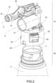
- a dispensing device for liquids such as detergent liquids, deodorizers and the like, is collectively indicated at 1.
- the dispensing device 1 comprises a bottle 2 for containing the liquid to be dispensed and a dispensing head 4, provided with a trigger 6, applied to the bottle 2.
- the bottle 2 comprises a bottle body 2a and a bottle neck 2b, in a single piece with the bottle body, for connecting with the dispensing head 4.
- the neck is made as a separate piece, suitably engaged with the bottle body.
- the dispensing head 4 comprises a chassis 10 for supporting the functional components for dispensing the product.
- the chassis 10 has a piston chamber 12, internally cylindrical, having extension along a chamber axis X, designed to accommodate slidably a piston.
- Said chassis 10 further comprises a dispensing duct 14, which extends along a dispensing axis Z, preferably parallel and distinct from the chamber axis X, into which the liquid dispensed from the piston chamber 12 is conveyed, preferably terminating with a dispensing chamber 16 provided with a dispensing port 18 for dispensing the liquid into the external environment.
- a dispensing duct 14 which extends along a dispensing axis Z, preferably parallel and distinct from the chamber axis X, into which the liquid dispensed from the piston chamber 12 is conveyed, preferably terminating with a dispensing chamber 16 provided with a dispensing port 18 for dispensing the liquid into the external environment.
- said chassis further comprises a coupling portion 20 for hinging the trigger 6; for example, said coupling portion 20 is arranged along the dispensing duct 14.
- said piston to the chassis 10 are applied said piston, a dispensing nozzle at the dispensing chamber 16, said trigger 6 on the coupling portion 20, suction, dispensing and venting valve means and a cover, which, preferably, covers at least part of the chassis, on the top and at the sides.
- a connection system comprises a main skirt 30 consisting of a typically cylindrical annular wall 32 having a central skirt axis Y; the main skirt 30 is intended to be connected to the neck 2b of the bottle 2.
- the main skirt 30 is made in one piece with the whole chassis 10.
- the main skirt is made separately and appropriately connected to the remaining part of the chassis.
- Said main skirt 30 further comprises a bottom 34 which closes the annular wall 32.
- the base 34 is orthogonal to the skirt axis Y and above it are found the piston chamber 12 and the dispensing duct 14.
- the main skirt 30 comprises a plurality of flexible tabs 40, 42, 44, arranged in the space delimited by the annular wall 32, projecting cantilevered therefrom.
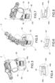
- the main skirt 30 comprises a first tab 40 ( figures 3 and 4 ), projecting internally from the annular wall 32, so as to be cantilevered; preferably, the first tab 40 is inclined inwards.
- the first tab 40 extends angularly from a first end 40a to a second end 40b.
- the first end 40a is joined to the annular wall 42 by a closing wall 40c, whereas, preferably, the second end 40b is free.
- a median plane of the closing wall 40c lies on an imaginary plane parallel to the skirt axis Y or on an imaginary plane containing the skirt axis Y.
- the main skirt 30 has a first window 50 through the annular wall 32, and the first tab 40 is placed inside the first window 50.
- the first tab 40 has a lower angular extension of the circumferential opening of the first window 50.
- the closing wall 40c joins the first end 40a of the first tab 40 with the respective lateral edge of the first window 50.
- the main skirt 30 further comprises a second tab 42, positioned angularly spaced from the first tab 40 ( figures 5 and 6 ).
- said second tab 42 projects internally from the annular wall 32, so as to be cantilevered; preferably, the second tab 42 is inclined inward.
- the second tab 42 is made in two parts 42', 42'', separated circumferentially; preferably, each part 42', 42'' has free ends.
- the main skirt 30 has a second window 52 through the annular wall 32 and said second tab 42 is placed inside the second window 52.
- the main skirt 30 further comprises a third tab 44, positioned angularly spaced from the first tab 40 and from the second tab 42 ( figures 7 and 8 ).
- said third tab 44 projects internally from the annular wall 32, so as to be cantilevered; preferably, the third tab 44 is inclined inward.
- the third tab 44 extends angularly from a first end 44a to a second end 44b.
- the first end 44a is joined to the annular wall 42 by a reinforcing wall 44c, while, preferably, the second end 44b is free.
- the reinforcing wall 44c has a decreasing thickness towards the annular wall 32.
- the main skirt 30 has a third window 54 through the annular wall 32 and said third tab 44 is located inside the third window 54.
- the reinforcing wall 44c meets the lower edge of the window 54 in an intermediate position between the ends.
- the first end 40a is arranged at the start of the first tab 40, i.e. before the second free end 40b; therefore, the closing wall 40c precedes said second end 40b.
- the inner surface 40ci of the closing wall 40c is connected to the inner side surface 32i of the annular wall 32, forming an obtuse angle therewith, so that, according to the clockwise direction C, a ramp is formed towards the inside of the main skirt 30.
- the first end 44a is arranged at the beginning of the third tab 44, i.e. before the second free end 44b; therefore, the reinforcing wall 44c precedes said second end 44b.
- the inner surface 44ci of the closing wall 44c forms an obtuse angle with the inner side surface 32i of the annular wall 32 so that, according to the clockwise direction C, a ramp is formed towards the inside of the main skirt 30.
- the main skirt 30 is intended to snap-fit with the neck 2b of the bottle 2.
- Said neck 2b provides for an annular edge 60, having a predefined axial height which circumferentially delimits the mouth of the bottle 2.
- the neck 2b provides for circumferential coupling regions 70, 72, 74 for the tabs 40, 42, 44 of the main skirt.
- the neck 2b provides for a first coupling region 70 for the coupling of the first tab 40 ( figure 12 ).
- the first coupling region 70 comprises a first sloping plane 70a, having a predefined angular extension, externally projecting from the outer surface of the neck; circumferentially, said first sloping plane 70a is delimited by a pair of guide elements 70b, 70c, which give it a downwardly converging funnel shape.
- a first pocket 76 having a predetermined angular extension, at least equal to that of the outlet section of the first sloping plane 70a, is arranged below the first sloping plane 70a, axially aligned therewith.
- the first pocket 76 is circumferentially delimited by a projecting element 76a and a stop wall 76b.
- the projecting element 76a is provided with a projecting ramp 76a', external to the first pocket 76, for facilitating snap-fitting by rotation into said first pocket 76.
- the first sloping surface 70a has a circumferential extension at least equal to that of the first tab 40 to facilitate snap-fitting by axial translation into said first pocket 76.
- the first pocket 76 has a circumferential extension so as to accommodate the first tab 40 and preferably greater than that of the first tab 40.
- the first coupling region 70 comprises a first outlet ramp 78, circumferentially flanked by the first sloping plane 70a and the first pocket 76.
- a first channel 79 is formed.
- Said first outlet ramp 78 has an inlet portion 78a substantially at the level of the lower edge of the first pocket 76, almost horizontal, and an outlet portion 78b substantially terminating at the height of the upper edge of the first, almost vertical sloping plane 70a.
- said first outlet ramp 78 has a sloping progression which suddenly increases from the inlet portion 78a to the outlet portion 78b, for example with an exponential or hyperbolic progression.
- the neck 2b provides a third coupling region 74 for coupling the third tab 44 ( figure 13 ).
- the third coupling region 74 comprises a first sloping plane 74a having a predefined angular extension externally projecting from the outer surface of the neck; circumferentially, said third sloping plane 74a is delimited by a pair of guide elements 74b, 74c, which give it a downwardly converging funnel shape.
- a third pocket 80 having a predetermined angular extension, at least equal to that of the outlet section of the second sloping plane 74a, is arranged below the third sloping plane 74a, aligned axially therewith.
- the third pocket 80 is circumferentially delimited by a projecting element 80a and a stop wall 80b.
- the projecting element 80a is provided with a projecting ramp 80a', external to the third pocket 80, for facilitating snap-fitting by rotation into said third pocket 80.
- the third sloping surface 74a has a circumferential extension at least equal to that of the third tab 44 to facilitate snap-fitting by axial translation into said third pocket 80.
- the third pocket 80 has a circumferential extension so as to accommodate the third tab 44 and preferably greater than that of the third tab 44.
- the third coupling region 74 comprises a third outlet ramp 82, circumferentially flanked by the third sloping plane 74a and the third pocket 80.
- a third channel 83 is formed.
- Said third outlet ramp 82 has a structure and functionality similar to that of the first outlet ramp 78.
- the neck 2b has a second coupling region 72 for the coupling of the second tab 42, for example comprising a second sloping plane and a second pocket.
- connection system further comprises an auxiliary window 90.
- the bottle 2 comprises a substantially rigid auxiliary tooth 100.
- the auxiliary window 90 is obtained through the annular wall 32 of the main skirt 30.
- said auxiliary window 90 is arranged circumferentially so that, in the clockwise direction C, proceeding from the first tab 40 towards the third tab 44, one encounters first said auxiliary window 90 and then said third tab 44.
- said auxiliary window 90 is arranged circumferentially so that, in the clockwise direction C, proceeding from the first window 50 to the third window 54, one encounters first said auxiliary window 90 and then said third window 54.
- the auxiliary window 90 is arranged axially below the lower edge of the first window 50 and the third window 54.
- the auxiliary tooth 100 protrudes from the outer surface of the neck 2b and is provided, at the top, with a tooth plane 102 inclined downwardly, like the sliding planes 70a, 74a, which forms an undercut 104.
- the sides circumferentially delimiting the tooth diverge towards the outside, so as to hinder, at least in part, the emerging of the tooth from the window by the relative rotation of the skirt with respect to the neck.
- the auxiliary tooth 100 is arranged in the third coupling region 74, and preferably in such a way that, in the clockwise direction C, proceeding from the third outlet ramp 82 to the third pocket 80, one encounters first said auxiliary tooth 100 and then said third pocket 80.
- the auxiliary tooth 100 is arranged axially at the lower edge of the third pocket 80.
- the auxiliary window 90 is suitable to snap-fit with the auxiliary tooth 100 to create a further rotational and axial constraint point between the main skirt 30 and the neck 2b.
- connection system further comprises an auxiliary rib 91 projecting from the inner surface of the annular wall 32 of the main skirt 30, flanked by the auxiliary window 90, so as to constitute a stop for the auxiliary tooth 100 when it emerges from the auxiliary window 90.
- the auxiliary rib 91 has a substantially axial progression and is delimited, at least on the side facing the auxiliary window 90, by an inclined side 93, to facilitate the emerging of the auxiliary tooth 100.
- said auxiliary rib 91 makes the intensity of the torque necessary for the first opening of the device less variable.
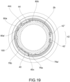
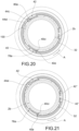
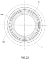
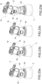
- the dispensing head 4 is axially insertable on the neck 2b, so that the dispensing device 1 is brought into the coupling configuration ( figures 14 to 19 and figure 23a ).
- the dispensing head 4 and the bottle 2 are arranged in the relative position of alignment when the first tab 40 is axially aligned with the first sloping plane 70a (consequently, the third tab 44 is aligned with the third pocket 80); this mutual arrangement generally corresponds to positioning the dispensing nozzle at the front of the device.
- the first tab 40 slides over the first sloping plane 70a and snaps into the first pocket 76, and, at the same time, the third tab 44 slides over the third sloping plane 74a and snaps into the third pocket 80.
- the second tab 42 slides to snap-fit and couple with the second coupling region 72.
- the auxiliary tooth 100 by causing a local deformation of the annular wall 32, snaps into the auxiliary window 90, facilitated by the tooth plane 102.
- the relative rotation of the chassis 10 with respect to the neck 2b causes the auxiliary tooth 100, locally deforming the annular wall area around the auxiliary window, to be forced out of said auxiliary window 90, in contrast with the annular wall 32, which undergoes localized deformation.
- the first tab 40 is pushed radially outwardly by the projecting element 76a of the first coupling region 70.
- said projecting element 76a acts on the inner surface 40ci of the closing wall 40c of the first tab 40, causing a deformation thereof.
- the third tab 44 is pushed radially outwardly by the projecting element 80a of the third coupling region 74.
- said projecting element 80a acts on the inner surface 44ci of the reinforcing wall 44c of the third tab 44, causing a deformation thereof.
- the first tab 40 surpasses the projecting element 76a and is placed in the first channel 79, while the third tab 44 surpasses the projecting element 80a and is placed in the third channel 83.
- the auxiliary tooth 100 continues to locally deform the annular wall 32.
- the first tab 40 moves along the first ramp 78 and the third tab 44 moves along the third ramp 82, thus guiding said tabs in an axial translation which axially disengages the dispensing head 4 and the bottle 2.
- the auxiliary tooth 100 overcoming the resistance to deformation of the annular wall 32, protrudes axially from the main skirt 30.
- the bottle according to the present invention solves the problem mentioned above, insofar as it ensures a good torque resistant to the mutual rotation both at the first opening and in the successive openings.
- the Applicant by performing some experimental tests, has, for example, shown how the first opening torque varies between 230Nm and 300Nm, while the torque for the fifth opening varies between 100Nm and 150Nm.
- the decay of the opening torque for devices of the prior art is decidedly more sudden, and generally passes from 300Nm for the first opening torque to 70Nm for the fifth opening torque.
- first and third tabs provided, respectively, with a closing wall and a reinforcing wall, which help make the system more rigid.
- the bottle solves the technical problem also by virtue of the synergistic combination of the effects of the tabs and the auxiliary tooth, since, for example, the deformation of the tabs causes a deformation of the annular wall in the vicinity of the auxiliary window, so that the emerging of the auxiliary tooth from said auxiliary window is facilitated.
- the auxiliary tooth participates in maintaining the opening torque, as once it leaves the auxiliary window, it works in contraction with the resistance to deformation of the annular wall, which remains substantially unchanged after numerous openings.
Landscapes
- Closures For Containers (AREA)
- Coating Apparatus (AREA)
Claims (14)
- Behälter (2) zur Kopplung mit einem Auslöse-Abgabekopf (4), wobei der Behälter (2) einen Behälterkörper (2a) und einen Behälterhals (2b) aufweist, der mit dem Behälterkörper einstückig ist (Absatz 15), wobei der Behälterhals (2b) einen ringförmigen Rand (60) mit einer vordefinierten axialen Höhe bereitstellt, der eine Mündung des Behälters (2) in Umfangsrichtung begrenzt, wobei axial unterhalb des ringförmigen Rands (60) auf einer Außenfläche davon der Behälterhals (2b) Umfangskopplungsbereiche (70, 72, 74) bereitstellt, wobei die Umfangskopplungsbereiche (70, 72, 74) einen ersten Kopplungsbereich (70) zur Kopplung mit einer ersten Lasche (40) des Auslöse-Abgabekopfs (4), einen zweiten Kopplungsbereich (72) zur Kopplung einer zweiten Lasche (42) des Auslöse-Abgabekopfs (4), einen dritten Kopplungsbereich (74) zur Kopplung mit einer dritten Lasche (44) des Auslöse-Abgabekopfs (4) aufweisen;
dadurch gekennzeichnet, dass der Behälterhals einen starren Hilfszahn (100) aufweist, der an der Oberseite eine nach unten geneigte Zahnebene (102) aufweist und eine Hinterschneidung (104) bildet; wobei der Hilfszahn (100) zur Kopplung mit einem Hilfsfenster (90) des Auslöse-Abgabekopfs (4) bereitgestellt ist, wobei der Hilfszahn (100) von einer Außenfläche des Behälterhalses (2b) vorspringt. - Behälter nach Anspruch 1, wobei der erste Kopplungsbereich (70) eine erste schräge Ebene (70a) mit einer vordefinierten Winkelerstreckung aufweist, die von der Außenfläche des Halses nach außen vorspringt, wobei in Umfangsrichtung die erste schräge Ebene (70a) durch ein Paar Führungselemente (70b, 70c) begrenzt ist, die ihr eine nach unten konvergierende Trichterform verleihen.
- Behälter nach Anspruch 2, wobei eine erste Tasche (76) mit einer vorbestimmten Winkelerstreckung, die zumindest gleich der eines Auslassabschnitts der ersten schrägen Ebene (70a) ist, unterhalb der ersten schrägen Ebene (70a) in axialer Ausrichtung damit angeordnet ist, wobei die erste Tasche (76) durch ein vorspringendes Element (76a) und eine Anschlagswand (76b) in Umfangsrichtung begrenzt ist.
- Behälter nach Anspruch 3, wobei das vorspringende Element (76a) mit einer vorspringenden Rampe (76a'), die außerhalb der ersten Tasche (76) liegt, zur Erleichterung eines Einrastens durch Drehung in die erste Tasche (76) versehen ist.
- Behälter nach einem der vorhergehenden Ansprüche, wobei der erste Kopplungsbereich (70) eine erste Auslassrampe (78) aufweist, die durch die erste schräge Ebene (70a) und die erste Tasche (76) in Umfangsrichtung flankiert wird, wobei zwischen der ersten Auslassrampe (78) auf einer Seite und der ersten schrägen Ebene (70a) und der ersten Tasche (76) auf der anderen ein erster Kanal (79) ausgebildet ist, wobei die erste Auslassrampe (78) einen Einlassabschnitt (78a) auf dem Niveau eines unteren Rands der ersten Tasche (76), der nahezu horizontal liegt, und einen Auslassabschnitt (78b) aufweist, der auf der Höhe eines oberen Rands der ersten vertikalen schrägen Ebene (70a) endet, wobei insgesamt die erste Auslassrampe (78) einen schrägen Verlauf aufweist, der von dem Einlassabschnitt (78a) zu dem Auslassabschnitt (78b) abrupt zunimmt.
- Behälter nach einem der vorhergehenden Ansprüche, wobei der dritte Kopplungsbereich (74) eine erste schräge Ebene (74a) mit einer vordefinierten Winkelerstreckung aufweist, die von einer Außenfläche des Behälterhalses nach außen vorspringt, wobei die dritte schräge Ebene (74a) durch ein Paar Führungselemente (74b, 74c) in Umfangsrichtung begrenzt ist, die ihr eine nach unten konvergierende Trichterform verleihen.
- Behälter nach einem der vorhergehenden Ansprüche, wobei eine dritte Tasche (80) mit einer vorbestimmten Winkelerstreckung, die zumindest gleich der eines Auslassabschnitts der zweiten schrägen Ebene (74a) ist, unterhalb der dritten schrägen Ebene (74a) in axialer Ausrichtung damit angeordnet ist, wobei die dritte Tasche (80) durch ein vorspringendes Element (80a) und eine Anschlagswand (80b) in Umfangsrichtung begrenzt ist.
- Behälter nach Anspruch 7, wobei das vorspringende Element (80a) mit einer vorspringenden Rampe (80a'), die außerhalb der dritten Tasche (80) liegt, zur Erleichterung eines Einrastens durch Drehung in die dritte Tasche (80) versehen ist.
- Behälter nach Anspruch 7 oder 8, wobei der Hilfszahn (100) an dem unteren Rand der dritten Tasche (80) axial angeordnet ist.
- Behälter nach einem der Ansprüche 7 bis 9, wobei der dritte Kopplungsbereich (74) eine dritte Auslassrampe (82) aufweist, die durch die dritte schräge Ebene (74a) und die dritte Tasche (80) in Umfangsrichtung flankiert wird,
wobei zwischen der dritten Auslassrampe (82) auf einer Seite und der dritten schrägen Ebene (74a) und der dritten Tasche (80) auf der anderen ein dritter Kanal (83) ausgebildet ist. - Behälter nach Anspruch 10, wobei der zweite Kopplungsbereich (72) eine zweite schräge Ebene und eine zweite Tasche aufweist.
- Behälter nach einem der vorhergehenden Ansprüche, wobei Seiten, die den Zahn in Umfangsrichtung begrenzen, nach außen auseinanderlaufen, um so zumindest zum Teil das Herauskommen des Zahns aus einem Fenster des Auslöse-Abgabekopfs durch die relative Drehung einer Einfassung des Auslöse-Abgabekopfs (4) in Bezug auf den Behälterhals zu behindern.
- Behälter nach einem der vorhergehenden Ansprüche, wobei der Hilfszahn (100) in dem dritten Kopplungsbereich (74) angeordnet ist.
- Auslöse-Abgabevorrichtung, aufweisend:- einen Behälter nach einem der vorhergehenden Ansprüche;- einen Abgabekopf, der auf den Behälterhals des Behälters aufgebracht ist.
Applications Claiming Priority (4)
| Application Number | Priority Date | Filing Date | Title |
|---|---|---|---|
| IT102017000085464A IT201700085464A1 (it) | 2017-07-26 | 2017-07-26 | Sistema di connessione fra flacone e testa di un dispositivo di erogazione a grilletto |
| IT201700143091 | 2017-12-12 | ||
| PCT/IB2018/053384 WO2019021069A1 (en) | 2017-07-26 | 2018-05-15 | CONNECTION SYSTEM BETWEEN A BOTTLE AND A DISTRIBUTION HEAD |
| EP18730112.2A EP3658295B1 (de) | 2017-07-26 | 2018-05-15 | Verbindungssystem zwischen einem behälter und einem abgabekopf |
Related Parent Applications (2)
| Application Number | Title | Priority Date | Filing Date |
|---|---|---|---|
| EP18730112.2A Division EP3658295B1 (de) | 2017-07-26 | 2018-05-15 | Verbindungssystem zwischen einem behälter und einem abgabekopf |
| EP18730112.2A Division-Into EP3658295B1 (de) | 2017-07-26 | 2018-05-15 | Verbindungssystem zwischen einem behälter und einem abgabekopf |
Publications (2)
| Publication Number | Publication Date |
|---|---|
| EP3733298A1 EP3733298A1 (de) | 2020-11-04 |
| EP3733298B1 true EP3733298B1 (de) | 2023-06-14 |
Family
ID=62563207
Family Applications (2)
| Application Number | Title | Priority Date | Filing Date |
|---|---|---|---|
| EP20181152.8A Active EP3733298B1 (de) | 2017-07-26 | 2018-05-15 | Behälter für einen trigger sprüher |
| EP18730112.2A Active EP3658295B1 (de) | 2017-07-26 | 2018-05-15 | Verbindungssystem zwischen einem behälter und einem abgabekopf |
Family Applications After (1)
| Application Number | Title | Priority Date | Filing Date |
|---|---|---|---|
| EP18730112.2A Active EP3658295B1 (de) | 2017-07-26 | 2018-05-15 | Verbindungssystem zwischen einem behälter und einem abgabekopf |
Country Status (6)
| Country | Link |
|---|---|
| US (1) | US11247222B2 (de) |
| EP (2) | EP3733298B1 (de) |
| BR (1) | BR112020000594B1 (de) |
| ES (2) | ES2954901T3 (de) |
| MX (1) | MX2020007658A (de) |
| WO (1) | WO2019021069A1 (de) |
Families Citing this family (2)
| Publication number | Priority date | Publication date | Assignee | Title |
|---|---|---|---|---|
| US11338309B2 (en) | 2017-07-26 | 2022-05-24 | Guala Dispensing S.P.A | Connection system between a bottle and a dispensing head |
| IT202200021234A1 (it) * | 2022-10-14 | 2024-04-14 | Guala Dispensing Spa | Telaio e guscio per un dispositivo di erogazione a grilletto |
Family Cites Families (12)
| Publication number | Priority date | Publication date | Assignee | Title |
|---|---|---|---|---|
| US3917097A (en) * | 1974-06-03 | 1975-11-04 | Gerhardt E Uhlig | Safety closure container |
| US4069942A (en) * | 1976-07-12 | 1978-01-24 | Eyelet Specialty Co., Inc. | Child-resistant pill dispenser |
| EP0176206A3 (de) * | 1984-08-17 | 1988-06-08 | The Clorox Company | Behälterverschluss |
| IT1290501B1 (it) | 1997-03-28 | 1998-12-04 | Guala Dispensing Srl | Attacco a baionetta tra una pompa spruzzatrice e un flacone di una sostanza da spruzzare |
| US6196423B1 (en) * | 2000-04-25 | 2001-03-06 | Innopak, Inc. | Child resistant overcap with safety collar and containing a child resistant slip collar for screw-on pump sprayers |
| US20060289679A1 (en) * | 2005-06-27 | 2006-12-28 | Johnson Kaj A | Modular sprayer |
| ITBS20070060A1 (it) * | 2007-04-18 | 2008-10-19 | Guala Dispensing Spa | Sistema di chiusura per un contenitore, ad esempio per erogatore a grilletto |
| DE102011008060B3 (de) * | 2011-01-07 | 2012-07-19 | Henkel Ag & Co. Kgaa | Verschlussvorrichtung für einen Behälter |
| JP5755020B2 (ja) | 2011-05-12 | 2015-07-29 | キャニヨン株式会社 | 容器の口部とキャップとのバヨネット型接続構造 |
| BR112017014444A2 (pt) * | 2015-03-05 | 2018-01-16 | Aptargroup Inc | montagem de encaixe e sobretampa para a mesma |
| US11338309B2 (en) * | 2017-07-26 | 2022-05-24 | Guala Dispensing S.P.A | Connection system between a bottle and a dispensing head |
| US11014107B2 (en) * | 2017-11-07 | 2021-05-25 | Guala Dispensing S.P.A. | Connection system |
-
2018
- 2018-05-15 EP EP20181152.8A patent/EP3733298B1/de active Active
- 2018-05-15 ES ES20181152T patent/ES2954901T3/es active Active
- 2018-05-15 US US16/633,631 patent/US11247222B2/en active Active
- 2018-05-15 BR BR112020000594-0A patent/BR112020000594B1/pt active IP Right Grant
- 2018-05-15 WO PCT/IB2018/053384 patent/WO2019021069A1/en not_active Ceased
- 2018-05-15 EP EP18730112.2A patent/EP3658295B1/de active Active
- 2018-05-15 ES ES18730112T patent/ES2966188T3/es active Active
-
2020
- 2020-01-10 MX MX2020007658A patent/MX2020007658A/es unknown
Also Published As
| Publication number | Publication date |
|---|---|
| BR112020000594B1 (pt) | 2022-12-06 |
| MX2020007658A (es) | 2020-09-18 |
| EP3733298A1 (de) | 2020-11-04 |
| US20210086213A1 (en) | 2021-03-25 |
| EP3658295A1 (de) | 2020-06-03 |
| ES2966188T3 (es) | 2024-04-18 |
| US11247222B2 (en) | 2022-02-15 |
| BR112020000594A2 (pt) | 2020-07-14 |
| WO2019021069A1 (en) | 2019-01-31 |
| ES2954901T3 (es) | 2023-11-27 |
| EP3658295B1 (de) | 2023-11-29 |
Similar Documents
| Publication | Publication Date | Title |
|---|---|---|
| US11338309B2 (en) | Connection system between a bottle and a dispensing head | |
| EP3706917B1 (de) | Verbindungssystem | |
| US7497354B2 (en) | Fluid dispenser | |
| EP2289480A3 (de) | Verschlusselement für Tablettenspender | |
| US10092921B2 (en) | Fluid product reservoir and dispenser incorporating such a reservoir | |
| EP3733298B1 (de) | Behälter für einen trigger sprüher | |
| EP3352911B1 (de) | Spender für flüssige bis pastöse massen | |
| CN107847396A (zh) | 用于安全的伸缩的卡扣配合在注射剂小瓶上的液体药物转移装置 | |
| JP2020525268A5 (ja) | クロマトグラフィシステム | |
| EP2995385A1 (de) | System zur Ausgabe eines Produkts unter Druck | |
| US20250303429A1 (en) | Device for dispensing a fluid product and method for priming same | |
| CN103596698B (zh) | 固定环以及使用这种环的流体制品分配器 | |
| EP3081312B1 (de) | Flüssigkeitsspender mit pumpe zum einmaligen gebrauch | |
| US20080035597A1 (en) | Child Resistant Closure | |
| DE60106874T2 (de) | Behälter mit einrastendem hals | |
| CN107249993B (zh) | 用于分配系统的闭环连接器 | |
| EP2383205B1 (de) | Behälter mit aufgeklappter rückwand | |
| EP3012029B1 (de) | Vorrichtung zur aufnahme einer flüssigen substanz | |
| US20090152270A1 (en) | Orientation system for a closure | |
| US20090045228A1 (en) | Covering member, method for making same and dispensing device using same | |
| WO1994018526A1 (de) | Vorrichtung zur portionierten entnahme von flüssigkeit | |
| SE529956C2 (sv) | Sprejanordning, metod för sprejning samt sätt för tillverkning av anordning | |
| BR122020016475B1 (pt) | Garrafa para acoplar com uma cabeça de dispensa de gatilho e dispositivo de dispensa de gatilho | |
| EP4087687B1 (de) | Snap-on ausgabekopf | |
| US10384833B2 (en) | Vent for attachment to the hollow handle of a jug container |
Legal Events
| Date | Code | Title | Description |
|---|---|---|---|
| PUAI | Public reference made under article 153(3) epc to a published international application that has entered the european phase |
Free format text: ORIGINAL CODE: 0009012 |
|
| STAA | Information on the status of an ep patent application or granted ep patent |
Free format text: STATUS: THE APPLICATION HAS BEEN PUBLISHED |
|
| AC | Divisional application: reference to earlier application |
Ref document number: 3658295 Country of ref document: EP Kind code of ref document: P |
|
| AK | Designated contracting states |
Kind code of ref document: A1 Designated state(s): AL AT BE BG CH CY CZ DE DK EE ES FI FR GB GR HR HU IE IS IT LI LT LU LV MC MK MT NL NO PL PT RO RS SE SI SK SM TR |
|
| AX | Request for extension of the european patent |
Extension state: BA ME |
|
| STAA | Information on the status of an ep patent application or granted ep patent |
Free format text: STATUS: REQUEST FOR EXAMINATION WAS MADE |
|
| 17P | Request for examination filed |
Effective date: 20210402 |
|
| RBV | Designated contracting states (corrected) |
Designated state(s): AL AT BE BG CH CY CZ DE DK EE ES FI FR GB GR HR HU IE IS IT LI LT LU LV MC MK MT NL NO PL PT RO RS SE SI SK SM TR |
|
| STAA | Information on the status of an ep patent application or granted ep patent |
Free format text: STATUS: EXAMINATION IS IN PROGRESS |
|
| 17Q | First examination report despatched |
Effective date: 20220412 |
|
| GRAP | Despatch of communication of intention to grant a patent |
Free format text: ORIGINAL CODE: EPIDOSNIGR1 |
|
| STAA | Information on the status of an ep patent application or granted ep patent |
Free format text: STATUS: GRANT OF PATENT IS INTENDED |
|
| GRAS | Grant fee paid |
Free format text: ORIGINAL CODE: EPIDOSNIGR3 |
|
| INTG | Intention to grant announced |
Effective date: 20230302 |
|
| GRAA | (expected) grant |
Free format text: ORIGINAL CODE: 0009210 |
|
| STAA | Information on the status of an ep patent application or granted ep patent |
Free format text: STATUS: THE PATENT HAS BEEN GRANTED |
|
| AC | Divisional application: reference to earlier application |
Ref document number: 3658295 Country of ref document: EP Kind code of ref document: P |
|
| AK | Designated contracting states |
Kind code of ref document: B1 Designated state(s): AL AT BE BG CH CY CZ DE DK EE ES FI FR GB GR HR HU IE IS IT LI LT LU LV MC MK MT NL NO PL PT RO RS SE SI SK SM TR |
|
| REG | Reference to a national code |
Ref country code: CH Ref legal event code: EP |
|
| REG | Reference to a national code |
Ref country code: DE Ref legal event code: R096 Ref document number: 602018052011 Country of ref document: DE |
|
| REG | Reference to a national code |
Ref country code: AT Ref legal event code: REF Ref document number: 1578837 Country of ref document: AT Kind code of ref document: T Effective date: 20230715 |
|
| REG | Reference to a national code |
Ref country code: LT Ref legal event code: MG9D |
|
| REG | Reference to a national code |
Ref country code: NL Ref legal event code: MP Effective date: 20230614 |
|
| PG25 | Lapsed in a contracting state [announced via postgrant information from national office to epo] |
Ref country code: SE Free format text: LAPSE BECAUSE OF FAILURE TO SUBMIT A TRANSLATION OF THE DESCRIPTION OR TO PAY THE FEE WITHIN THE PRESCRIBED TIME-LIMIT Effective date: 20230614 Ref country code: NO Free format text: LAPSE BECAUSE OF FAILURE TO SUBMIT A TRANSLATION OF THE DESCRIPTION OR TO PAY THE FEE WITHIN THE PRESCRIBED TIME-LIMIT Effective date: 20230914 |
|
| REG | Reference to a national code |
Ref country code: AT Ref legal event code: MK05 Ref document number: 1578837 Country of ref document: AT Kind code of ref document: T Effective date: 20230614 |
|
| REG | Reference to a national code |
Ref country code: ES Ref legal event code: FG2A Ref document number: 2954901 Country of ref document: ES Kind code of ref document: T3 Effective date: 20231127 |
|
| PG25 | Lapsed in a contracting state [announced via postgrant information from national office to epo] |
Ref country code: RS Free format text: LAPSE BECAUSE OF FAILURE TO SUBMIT A TRANSLATION OF THE DESCRIPTION OR TO PAY THE FEE WITHIN THE PRESCRIBED TIME-LIMIT Effective date: 20230614 Ref country code: NL Free format text: LAPSE BECAUSE OF FAILURE TO SUBMIT A TRANSLATION OF THE DESCRIPTION OR TO PAY THE FEE WITHIN THE PRESCRIBED TIME-LIMIT Effective date: 20230614 Ref country code: LV Free format text: LAPSE BECAUSE OF FAILURE TO SUBMIT A TRANSLATION OF THE DESCRIPTION OR TO PAY THE FEE WITHIN THE PRESCRIBED TIME-LIMIT Effective date: 20230614 Ref country code: LT Free format text: LAPSE BECAUSE OF FAILURE TO SUBMIT A TRANSLATION OF THE DESCRIPTION OR TO PAY THE FEE WITHIN THE PRESCRIBED TIME-LIMIT Effective date: 20230614 Ref country code: HR Free format text: LAPSE BECAUSE OF FAILURE TO SUBMIT A TRANSLATION OF THE DESCRIPTION OR TO PAY THE FEE WITHIN THE PRESCRIBED TIME-LIMIT Effective date: 20230614 Ref country code: GR Free format text: LAPSE BECAUSE OF FAILURE TO SUBMIT A TRANSLATION OF THE DESCRIPTION OR TO PAY THE FEE WITHIN THE PRESCRIBED TIME-LIMIT Effective date: 20230915 |
|
| PG25 | Lapsed in a contracting state [announced via postgrant information from national office to epo] |
Ref country code: FI Free format text: LAPSE BECAUSE OF FAILURE TO SUBMIT A TRANSLATION OF THE DESCRIPTION OR TO PAY THE FEE WITHIN THE PRESCRIBED TIME-LIMIT Effective date: 20230614 |
|
| PG25 | Lapsed in a contracting state [announced via postgrant information from national office to epo] |
Ref country code: SK Free format text: LAPSE BECAUSE OF FAILURE TO SUBMIT A TRANSLATION OF THE DESCRIPTION OR TO PAY THE FEE WITHIN THE PRESCRIBED TIME-LIMIT Effective date: 20230614 |
|
| PG25 | Lapsed in a contracting state [announced via postgrant information from national office to epo] |
Ref country code: IS Free format text: LAPSE BECAUSE OF FAILURE TO SUBMIT A TRANSLATION OF THE DESCRIPTION OR TO PAY THE FEE WITHIN THE PRESCRIBED TIME-LIMIT Effective date: 20231014 |
|
| PG25 | Lapsed in a contracting state [announced via postgrant information from national office to epo] |
Ref country code: SM Free format text: LAPSE BECAUSE OF FAILURE TO SUBMIT A TRANSLATION OF THE DESCRIPTION OR TO PAY THE FEE WITHIN THE PRESCRIBED TIME-LIMIT Effective date: 20230614 Ref country code: SK Free format text: LAPSE BECAUSE OF FAILURE TO SUBMIT A TRANSLATION OF THE DESCRIPTION OR TO PAY THE FEE WITHIN THE PRESCRIBED TIME-LIMIT Effective date: 20230614 Ref country code: RO Free format text: LAPSE BECAUSE OF FAILURE TO SUBMIT A TRANSLATION OF THE DESCRIPTION OR TO PAY THE FEE WITHIN THE PRESCRIBED TIME-LIMIT Effective date: 20230614 Ref country code: PT Free format text: LAPSE BECAUSE OF FAILURE TO SUBMIT A TRANSLATION OF THE DESCRIPTION OR TO PAY THE FEE WITHIN THE PRESCRIBED TIME-LIMIT Effective date: 20231016 Ref country code: IS Free format text: LAPSE BECAUSE OF FAILURE TO SUBMIT A TRANSLATION OF THE DESCRIPTION OR TO PAY THE FEE WITHIN THE PRESCRIBED TIME-LIMIT Effective date: 20231014 Ref country code: EE Free format text: LAPSE BECAUSE OF FAILURE TO SUBMIT A TRANSLATION OF THE DESCRIPTION OR TO PAY THE FEE WITHIN THE PRESCRIBED TIME-LIMIT Effective date: 20230614 Ref country code: CZ Free format text: LAPSE BECAUSE OF FAILURE TO SUBMIT A TRANSLATION OF THE DESCRIPTION OR TO PAY THE FEE WITHIN THE PRESCRIBED TIME-LIMIT Effective date: 20230614 Ref country code: AT Free format text: LAPSE BECAUSE OF FAILURE TO SUBMIT A TRANSLATION OF THE DESCRIPTION OR TO PAY THE FEE WITHIN THE PRESCRIBED TIME-LIMIT Effective date: 20230614 |
|
| PG25 | Lapsed in a contracting state [announced via postgrant information from national office to epo] |
Ref country code: PL Free format text: LAPSE BECAUSE OF FAILURE TO SUBMIT A TRANSLATION OF THE DESCRIPTION OR TO PAY THE FEE WITHIN THE PRESCRIBED TIME-LIMIT Effective date: 20230614 |
|
| REG | Reference to a national code |
Ref country code: DE Ref legal event code: R097 Ref document number: 602018052011 Country of ref document: DE |
|
| PLBE | No opposition filed within time limit |
Free format text: ORIGINAL CODE: 0009261 |
|
| STAA | Information on the status of an ep patent application or granted ep patent |
Free format text: STATUS: NO OPPOSITION FILED WITHIN TIME LIMIT |
|
| PG25 | Lapsed in a contracting state [announced via postgrant information from national office to epo] |
Ref country code: DK Free format text: LAPSE BECAUSE OF FAILURE TO SUBMIT A TRANSLATION OF THE DESCRIPTION OR TO PAY THE FEE WITHIN THE PRESCRIBED TIME-LIMIT Effective date: 20230614 |
|
| PG25 | Lapsed in a contracting state [announced via postgrant information from national office to epo] |
Ref country code: SI Free format text: LAPSE BECAUSE OF FAILURE TO SUBMIT A TRANSLATION OF THE DESCRIPTION OR TO PAY THE FEE WITHIN THE PRESCRIBED TIME-LIMIT Effective date: 20230614 |
|
| 26N | No opposition filed |
Effective date: 20240315 |
|
| PG25 | Lapsed in a contracting state [announced via postgrant information from national office to epo] |
Ref country code: SI Free format text: LAPSE BECAUSE OF FAILURE TO SUBMIT A TRANSLATION OF THE DESCRIPTION OR TO PAY THE FEE WITHIN THE PRESCRIBED TIME-LIMIT Effective date: 20230614 |
|
| PG25 | Lapsed in a contracting state [announced via postgrant information from national office to epo] |
Ref country code: BG Free format text: LAPSE BECAUSE OF FAILURE TO SUBMIT A TRANSLATION OF THE DESCRIPTION OR TO PAY THE FEE WITHIN THE PRESCRIBED TIME-LIMIT Effective date: 20230614 |
|
| PG25 | Lapsed in a contracting state [announced via postgrant information from national office to epo] |
Ref country code: BG Free format text: LAPSE BECAUSE OF FAILURE TO SUBMIT A TRANSLATION OF THE DESCRIPTION OR TO PAY THE FEE WITHIN THE PRESCRIBED TIME-LIMIT Effective date: 20230614 |
|
| REG | Reference to a national code |
Ref country code: CH Ref legal event code: PL |
|
| PG25 | Lapsed in a contracting state [announced via postgrant information from national office to epo] |
Ref country code: MC Free format text: LAPSE BECAUSE OF FAILURE TO SUBMIT A TRANSLATION OF THE DESCRIPTION OR TO PAY THE FEE WITHIN THE PRESCRIBED TIME-LIMIT Effective date: 20230614 |
|
| PG25 | Lapsed in a contracting state [announced via postgrant information from national office to epo] |
Ref country code: LU Free format text: LAPSE BECAUSE OF NON-PAYMENT OF DUE FEES Effective date: 20240515 |
|
| PG25 | Lapsed in a contracting state [announced via postgrant information from national office to epo] |
Ref country code: MC Free format text: LAPSE BECAUSE OF FAILURE TO SUBMIT A TRANSLATION OF THE DESCRIPTION OR TO PAY THE FEE WITHIN THE PRESCRIBED TIME-LIMIT Effective date: 20230614 Ref country code: LU Free format text: LAPSE BECAUSE OF NON-PAYMENT OF DUE FEES Effective date: 20240515 Ref country code: CH Free format text: LAPSE BECAUSE OF NON-PAYMENT OF DUE FEES Effective date: 20240531 |
|
| REG | Reference to a national code |
Ref country code: BE Ref legal event code: MM Effective date: 20240531 |
|
| PG25 | Lapsed in a contracting state [announced via postgrant information from national office to epo] |
Ref country code: IE Free format text: LAPSE BECAUSE OF NON-PAYMENT OF DUE FEES Effective date: 20240515 |
|
| PG25 | Lapsed in a contracting state [announced via postgrant information from national office to epo] |
Ref country code: BE Free format text: LAPSE BECAUSE OF NON-PAYMENT OF DUE FEES Effective date: 20240531 |
|
| PGFP | Annual fee paid to national office [announced via postgrant information from national office to epo] |
Ref country code: IT Payment date: 20250306 Year of fee payment: 8 |
|
| PGFP | Annual fee paid to national office [announced via postgrant information from national office to epo] |
Ref country code: DE Payment date: 20250523 Year of fee payment: 8 |
|
| PGFP | Annual fee paid to national office [announced via postgrant information from national office to epo] |
Ref country code: ES Payment date: 20250602 Year of fee payment: 8 |
|
| PGFP | Annual fee paid to national office [announced via postgrant information from national office to epo] |
Ref country code: FR Payment date: 20250430 Year of fee payment: 8 |
|
| PG25 | Lapsed in a contracting state [announced via postgrant information from national office to epo] |
Ref country code: CY Free format text: LAPSE BECAUSE OF FAILURE TO SUBMIT A TRANSLATION OF THE DESCRIPTION OR TO PAY THE FEE WITHIN THE PRESCRIBED TIME-LIMIT; INVALID AB INITIO Effective date: 20180515 |
|
| PG25 | Lapsed in a contracting state [announced via postgrant information from national office to epo] |
Ref country code: HU Free format text: LAPSE BECAUSE OF FAILURE TO SUBMIT A TRANSLATION OF THE DESCRIPTION OR TO PAY THE FEE WITHIN THE PRESCRIBED TIME-LIMIT; INVALID AB INITIO Effective date: 20180515 |
|
| PGFP | Annual fee paid to national office [announced via postgrant information from national office to epo] |
Ref country code: GB Payment date: 20260312 Year of fee payment: 9 |