EP3733342A1 - Transport installation - Google Patents
Transport installation Download PDFInfo
- Publication number
- EP3733342A1 EP3733342A1 EP20171889.7A EP20171889A EP3733342A1 EP 3733342 A1 EP3733342 A1 EP 3733342A1 EP 20171889 A EP20171889 A EP 20171889A EP 3733342 A1 EP3733342 A1 EP 3733342A1
- Authority
- EP
- European Patent Office
- Prior art keywords
- carrier
- product holder
- product
- alignment
- holder
- Prior art date
- Legal status (The legal status is an assumption and is not a legal conclusion. Google has not performed a legal analysis and makes no representation as to the accuracy of the status listed.)
- Granted
Links
Images


Classifications
-
- B—PERFORMING OPERATIONS; TRANSPORTING
- B65—CONVEYING; PACKING; STORING; HANDLING THIN OR FILAMENTARY MATERIAL
- B65G—TRANSPORT OR STORAGE DEVICES, e.g. CONVEYORS FOR LOADING OR TIPPING, SHOP CONVEYOR SYSTEMS OR PNEUMATIC TUBE CONVEYORS
- B65G47/00—Article or material-handling devices associated with conveyors; Methods employing such devices
- B65G47/74—Feeding, transfer, or discharging devices of particular kinds or types
- B65G47/88—Separating or stopping elements, e.g. fingers
- B65G47/8807—Separating or stopping elements, e.g. fingers with one stop
- B65G47/8815—Reciprocating stop, moving up or down in the path of the article
-
- B—PERFORMING OPERATIONS; TRANSPORTING
- B23—MACHINE TOOLS; METAL-WORKING NOT OTHERWISE PROVIDED FOR
- B23Q—DETAILS, COMPONENTS, OR ACCESSORIES FOR MACHINE TOOLS, e.g. ARRANGEMENTS FOR COPYING OR CONTROLLING; MACHINE TOOLS IN GENERAL CHARACTERISED BY THE CONSTRUCTION OF PARTICULAR DETAILS OR COMPONENTS; COMBINATIONS OR ASSOCIATIONS OF METAL-WORKING MACHINES, NOT DIRECTED TO A PARTICULAR RESULT
- B23Q16/00—Equipment for precise positioning of tool or work into particular locations not otherwise provided for
- B23Q16/02—Indexing equipment
- B23Q16/04—Indexing equipment having intermediate members, e.g. pawls, for locking the relatively movable parts in the indexed position
- B23Q16/043—Indexing equipment having intermediate members, e.g. pawls, for locking the relatively movable parts in the indexed position with a reciprocating or oscillating drive
-
- B—PERFORMING OPERATIONS; TRANSPORTING
- B23—MACHINE TOOLS; METAL-WORKING NOT OTHERWISE PROVIDED FOR
- B23Q—DETAILS, COMPONENTS, OR ACCESSORIES FOR MACHINE TOOLS, e.g. ARRANGEMENTS FOR COPYING OR CONTROLLING; MACHINE TOOLS IN GENERAL CHARACTERISED BY THE CONSTRUCTION OF PARTICULAR DETAILS OR COMPONENTS; COMBINATIONS OR ASSOCIATIONS OF METAL-WORKING MACHINES, NOT DIRECTED TO A PARTICULAR RESULT
- B23Q7/00—Arrangements for handling work specially combined with or arranged in, or specially adapted for use in connection with, machine tools, e.g. for conveying, loading, positioning, discharging, sorting
- B23Q7/14—Arrangements for handling work specially combined with or arranged in, or specially adapted for use in connection with, machine tools, e.g. for conveying, loading, positioning, discharging, sorting co-ordinated in production lines
- B23Q7/1426—Arrangements for handling work specially combined with or arranged in, or specially adapted for use in connection with, machine tools, e.g. for conveying, loading, positioning, discharging, sorting co-ordinated in production lines with work holders not rigidly fixed to the transport devices
- B23Q7/1447—Arrangements for handling work specially combined with or arranged in, or specially adapted for use in connection with, machine tools, e.g. for conveying, loading, positioning, discharging, sorting co-ordinated in production lines with work holders not rigidly fixed to the transport devices using endless conveyors
-
- B—PERFORMING OPERATIONS; TRANSPORTING
- B65—CONVEYING; PACKING; STORING; HANDLING THIN OR FILAMENTARY MATERIAL
- B65G—TRANSPORT OR STORAGE DEVICES, e.g. CONVEYORS FOR LOADING OR TIPPING, SHOP CONVEYOR SYSTEMS OR PNEUMATIC TUBE CONVEYORS
- B65G17/00—Conveyors having an endless traction element, e.g. a chain, transmitting movement to a continuous or substantially-continuous load-carrying surface or to a series of individual load-carriers; Endless-chain conveyors in which the chains form the load-carrying surface
- B65G17/002—Conveyors having an endless traction element, e.g. a chain, transmitting movement to a continuous or substantially-continuous load-carrying surface or to a series of individual load-carriers; Endless-chain conveyors in which the chains form the load-carrying surface comprising load carriers resting on the traction element
-
- B—PERFORMING OPERATIONS; TRANSPORTING
- B65—CONVEYING; PACKING; STORING; HANDLING THIN OR FILAMENTARY MATERIAL
- B65G—TRANSPORT OR STORAGE DEVICES, e.g. CONVEYORS FOR LOADING OR TIPPING, SHOP CONVEYOR SYSTEMS OR PNEUMATIC TUBE CONVEYORS
- B65G17/00—Conveyors having an endless traction element, e.g. a chain, transmitting movement to a continuous or substantially-continuous load-carrying surface or to a series of individual load-carriers; Endless-chain conveyors in which the chains form the load-carrying surface
- B65G17/30—Details; Auxiliary devices
- B65G17/32—Individual load-carriers
-
- B—PERFORMING OPERATIONS; TRANSPORTING
- B65—CONVEYING; PACKING; STORING; HANDLING THIN OR FILAMENTARY MATERIAL
- B65G—TRANSPORT OR STORAGE DEVICES, e.g. CONVEYORS FOR LOADING OR TIPPING, SHOP CONVEYOR SYSTEMS OR PNEUMATIC TUBE CONVEYORS
- B65G35/00—Mechanical conveyors not otherwise provided for
- B65G35/06—Mechanical conveyors not otherwise provided for comprising a load-carrier moving along a path, e.g. a closed path, and adapted to be engaged by any one of a series of traction elements spaced along the path
-
- B—PERFORMING OPERATIONS; TRANSPORTING
- B65—CONVEYING; PACKING; STORING; HANDLING THIN OR FILAMENTARY MATERIAL
- B65G—TRANSPORT OR STORAGE DEVICES, e.g. CONVEYORS FOR LOADING OR TIPPING, SHOP CONVEYOR SYSTEMS OR PNEUMATIC TUBE CONVEYORS
- B65G47/00—Article or material-handling devices associated with conveyors; Methods employing such devices
- B65G47/74—Feeding, transfer, or discharging devices of particular kinds or types
- B65G47/88—Separating or stopping elements, e.g. fingers
- B65G47/8807—Separating or stopping elements, e.g. fingers with one stop
- B65G47/8869—Separating or stopping elements, e.g. fingers with one stop stopping or lifting all articles from a conveyor
-
- G—PHYSICS
- G01—MEASURING; TESTING
- G01G—WEIGHING
- G01G19/00—Weighing apparatus or methods adapted for special purposes not provided for in the preceding groups
- G01G19/02—Weighing apparatus or methods adapted for special purposes not provided for in the preceding groups for weighing wheeled or rolling bodies, e.g. vehicles
- G01G19/03—Weighing apparatus or methods adapted for special purposes not provided for in the preceding groups for weighing wheeled or rolling bodies, e.g. vehicles for weighing during motion
- G01G19/035—Weighing apparatus or methods adapted for special purposes not provided for in the preceding groups for weighing wheeled or rolling bodies, e.g. vehicles for weighing during motion using electrical weight-sensitive devices
-
- B—PERFORMING OPERATIONS; TRANSPORTING
- B65—CONVEYING; PACKING; STORING; HANDLING THIN OR FILAMENTARY MATERIAL
- B65G—TRANSPORT OR STORAGE DEVICES, e.g. CONVEYORS FOR LOADING OR TIPPING, SHOP CONVEYOR SYSTEMS OR PNEUMATIC TUBE CONVEYORS
- B65G2203/00—Indexing code relating to control or detection of the articles or the load carriers during conveying
- B65G2203/02—Control or detection
- B65G2203/0208—Control or detection relating to the transported articles
- B65G2203/0216—Codes or marks on the article
-
- B—PERFORMING OPERATIONS; TRANSPORTING
- B65—CONVEYING; PACKING; STORING; HANDLING THIN OR FILAMENTARY MATERIAL
- B65G—TRANSPORT OR STORAGE DEVICES, e.g. CONVEYORS FOR LOADING OR TIPPING, SHOP CONVEYOR SYSTEMS OR PNEUMATIC TUBE CONVEYORS
- B65G2203/00—Indexing code relating to control or detection of the articles or the load carriers during conveying
- B65G2203/02—Control or detection
- B65G2203/0208—Control or detection relating to the transported articles
- B65G2203/0258—Weight of the article
-
- B—PERFORMING OPERATIONS; TRANSPORTING
- B65—CONVEYING; PACKING; STORING; HANDLING THIN OR FILAMENTARY MATERIAL
- B65G—TRANSPORT OR STORAGE DEVICES, e.g. CONVEYORS FOR LOADING OR TIPPING, SHOP CONVEYOR SYSTEMS OR PNEUMATIC TUBE CONVEYORS
- B65G2203/00—Indexing code relating to control or detection of the articles or the load carriers during conveying
- B65G2203/04—Detection means
-
- B—PERFORMING OPERATIONS; TRANSPORTING
- B65—CONVEYING; PACKING; STORING; HANDLING THIN OR FILAMENTARY MATERIAL
- B65G—TRANSPORT OR STORAGE DEVICES, e.g. CONVEYORS FOR LOADING OR TIPPING, SHOP CONVEYOR SYSTEMS OR PNEUMATIC TUBE CONVEYORS
- B65G2811/00—Indexing codes relating to common features for more than one conveyor kind or type
- B65G2811/06—Devices controlling the relative position of articles
- B65G2811/0621—Devices controlling the relative position of articles by modifying the orientation or position of articles
Definitions
- the present invention relates to a conveyor for transporting products.
- Industrial plants for the production or packaging of goods often include conveyor lines along which the goods are transported one after the other to different processing stations.
- processing stations can in particular include sorters, scales, packaging and inspection machines and marking devices. Further devices known to the person skilled in the art are also conceivable in order to treat the products accordingly depending on the desired processing.
- the products are moved to the individual processing stations by means of a conveyor device.
- Special conveyor members (drivers, hooks, etc.) are moved along a conveyor element, for example a rail, in a conveyor device and, in turn, can be coupled to individual carriers.
- Each carrier is designed to hold one or more products.
- Conceivable is, for example, a carriage or scales driven by a conveyor chain or a cable, serving as a carrier, or a group of carriages or carriages with which the products can be picked up directly or indirectly in order to bring them into and out of the individual processing stations transport.
- the carriers transported along the conveyor line are tailored to the goods to be transported and have special contours or dimensions in order to be able to safely pick up and transport the goods.
- the carriers can be connected to the conveyor links by simply inserting, screwing, locking, etc.
- the carrier allows different products to be transported with the same conveyor, for example by designing the upper area of the carrier to accommodate different products, while the bottom is designed for this to couple with the links of a front device.
- the product holders can be placed on or inserted into the carriers and serve to directly pick up the product to be transported.
- a product holder can be designed, for example, to place slices of sausage or cheese.
- Product holders for holding flowable or free-flowing products are also known.
- the main task of the carriers is to transport goods along the conveyor line, without any special requirements for the highly precise positioning of the carriers during transport or at the individual processing stations. As a rule, it is sufficient to position the goods transported by the carriers in the individual processing stations within predeterminable rough tolerances in order to be able to pack the products there, for example, or to be able to irradiate them for testing purposes. If the carriers are transported, for example, along a rail, the positioning accuracy that results from the coupling between the rail and the carrier is usually sufficient in the individual processing stations. Positioning inaccuracies can result from an existing mechanical play perpendicular to the conveying direction (hereinafter "Y-direction") between the rail and the carrier. Positioning tolerances can also occur in the conveying direction (hereinafter "X-direction”), for example when the carriers are driven by a chain with play, a gear or a spindle. Such positioning tolerances are acceptable for a number of machining stations.
- a processing station designed as a scale In order to be able to weigh a product in a processing station designed as a scale, it is expedient to "release" the product (possibly together with a known preload). This is understood to mean the state in which the weight of the product (possibly with preload) is completely introduced into the load receptor of a load cell of the scale without a positive or non-positive connection between the product and a component that is not to be weighed.
- the product holder picked up by the carrier often forms a preload in practice, that is, it is weighed together with the product.
- the product holder must therefore be completely decoupled ("released") from the carrier assigned to it for weighing in order to avoid a force shunt and thus a falsified weighing result.
- the position of the carrier in space in particular in the XY plane, must first be specified or known within narrow tolerances so that the product holder can be lifted out of the carrier as centrally as possible during the subsequent release without tilting or slipping. Only then can the release be achieved by a relatively simple, small and fast relative movement between the carrier and the product holder.
- the rough tolerances with which carriers known from the prior art are moved along the conveying path are therefore unsuitable for aligning the product holders transported with the carriers with sufficient accuracy.
- the object of the invention was therefore to offer a device and a method with which the carriers can be aligned precisely to the extent that a subsequent release of the product holder relative to the carrier is easily and quickly possible.
- the object is achieved by a conveyor device according to claim 1 and a method according to claim 16. Further advantageous embodiments result from the subclaims.
- the invention is based on the knowledge of being able to preposition a carrier transported along a conveyor device in a processing position as precisely as possible with the help of special alignment means, so that the subsequent release is possible by a simple relative movement between the carrier and the product holder, preferably by only one-dimensional movement.
- the first alignment means provided according to the invention for aligning the carrier are configured in such a way that they can transfer a carrier that has arrived in a processing position along the conveying path into a predetermined carrier target position. This is done by loading and moving the carrier relative to the conveyor device or another component, at least with respect to its horizontal Arrangement in the room is stationary.
- the first alignment means according to the invention ensure the transfer of the carrier that has arrived in the processing position into the precisely specifiable target carrier position.
- the carrier can thus be displaced and / or tilted relative to the conveying device or a component connected to it, in order to enable the subsequent exposure of the product holder received by the carrier in a simple manner.
- the coupling between the conveying device and the carrier is preferably selected within rough tolerances in such a way that the precise alignment of the carrier effected by the first alignment means moves within these tolerances.
- the first alignment means which are designed to be at least partially movable, expediently comprise at least one displaceable alignment element.
- the carrier can be loaded and shifted or tilted for alignment after reaching the processing position.
- the alignment element expediently has contact surfaces which, when the alignment element moves relative to the carrier, come into engagement with the carrier and, when the movement continues, exert forces on the carrier in order to move and / or tilt the carrier into the desired target position.
- the movement of the first alignment means relative to the carrier can take place, for example, by a linear drive or other electromechanical drive means known to those skilled in the art.
- the alignment can also take place using the movement of the carrier along the conveying path, for example in that the carrier is acted upon by lateral guide means while it is moving into the processing position.
- the exact alignment of the carrier in the X direction can be achieved, for example, by a stop at the processing position that can be pivoted into the conveying path. After the stop has been reached, the carrier is also precisely positioned in the Y direction due to the lateral guide means.
- An alternative, preferred embodiment below provides that the first alignment means only interact with the carrier when the carrier has reached the processing position and has already stopped there. In this case, the machining position is only defined within rough tolerances, and the carrier can still be displaced in particular in the X and Y directions.
- the first alignment means comprise at least one mandrel formed around a longitudinal axis, which can be moved into a recess or into an opening or bore of the carrier for aligning the carrier against a guide surface on the carrier.
- the mandrel and the guide surfaces on the carrier that interact with it are designed so that a movement of the mandrel in a first direction (in particular in a direction Z perpendicular to the XY plane) simultaneously moves the carrier in the two directions X and perpendicular to the Z direction Y aligns.
- the mandrel is preferably stationary with respect to its X and Y position, while the carrier can be aligned differently and thus in various ways in the X-Y plane, ie also relative to the conveying device.
- Several mandrels spaced apart from one another or comparable alignment elements can still simplify the alignment of the carrier, since in this way a certain rotational position in the X-Y plane can also be specified.
- An advantageous embodiment of the invention further provides that second alignment means are provided in order to transfer (release) the product holder relative to the carrier in a predeterminable target product holder position, which is defined at least with regard to its X and Y position. It is thus possible according to the invention, after the carrier has been previously aligned in space, to release the product holder from the carrier in order to carry out the weighing process.
- the first alignment means serve to align the carrier of the conveying device that is not to be weighed exactly in space for the later release of the product holder
- the second alignment means preferably serve to release the product holder relative to the carrier.
- Alignment surfaces or contours are expediently provided on the product holder which are designed to interact with a centering unit that is moved relative to the product holder. Centering unit and alignment surfaces together form the second alignment means.
- the second alignment means can be designed analogously to the first alignment means so that contact surfaces of both components approach or touch each other during a relative movement between the centering unit and the product holder, in order to exert forces on the product holder and to align it, in particular in the X-Y plane.
- the product holder could be provided on a side facing the carrier with conically running surfaces which interact with suitable guide surfaces or edges of the carrier and thus precisely position the product holder in the carrier relative to the carrier.
- the second alignment elements merely as stop elements which act against one another and which are used to lift the product holder out of the carrier. If the product holder is arranged in the carrier in such a way that, by lifting the product holder vertically out of the carrier, a mechanical separation of the product holder from the carrier is achieved at the same time, then this is sufficient for the release.
- the centering unit is not used for centering (i.e. for horizontal alignment of the product holder relative to the centering unit), but only for lifting the product holder in the Z direction without changing the spatial position of the product holder in the X or Y direction.
- the conveying device comprises a weighing cell which is designed to record the weight of a product holder loaded or unloaded with product and released from its associated carrier in the processing position, the weighing cell having a load introduction section comprising the centering unit for introducing the to weighing load in the load cell.
- the load cell has the task of weighing the products transported along the conveyor route. For this purpose, the product holders receiving the products must be released in the manner described above.
- the weight force to be determined is introduced by the product holder into the load application section of the weighing cell and converted into an evaluable signal within the weighing cell via a mechanism known to those skilled in the art.
- the load introduction section preferably comprises the centering unit with which the product holder is exposed relative to the carrier.
- the product holder is then released by first aligning the carrier in space using the first alignment means.
- the carrier (with the product holder it has received) is aligned in the processing position in such a way that the product holder for the subsequent release process is positioned relative to the centering unit so that the release can take place solely with the aid of a relative movement between the centering unit and product holder.
- the load cell with its load introduction section including the centering unit is designed to be displaceable to such an extent that the weight of the product holder is introduced into the load introduction section without force shunting (release) or is decoupled from it (the product holder rests on the carrier).
- the process of releasing can preferably take place in such a way that the load cell with its load introduction section and the centering unit arranged thereon is moved towards the product holder relative to the latter, in order to thereby receive the product holder and detach it from the carrier.
- the weighing cell is expediently arranged on a lifting device so that its load introduction section (preferably from below) can be moved upwards against the product holder in order to lift it out of the carrier.
- the load cell is lowered again so that the product holder is picked up again by the carrier.
- the carrier together with the product holder can be moved along the conveying path to the next processing station.
- the product holder could also be lowered onto an essentially stationary load cell.
- the conveying device is designed such that the release is effected by aligning the carrier in space by means of first alignment elements with subsequent or temporally overlapping or simultaneous alignment or exposure of the product holder relative to the carrier by means of the second alignment elements.
- first alignment elements in particular the aforementioned mandrel
- first alignment elements are rigidly or largely rigidly coupled to the load cell, so that these alignment elements come into engagement with the carrier to be aligned and align it by preferably moving the load cell vertically or transfer it to the desired carrier position.
- both parts of the first alignment means for example the mandrel
- parts of the second alignment means namely the centering unit
- the first alignment means cooperate with the carrier in order to align it in space, while at the same time or with a time offset the centering unit cooperates with the product holder in order to lift it out of the carrier.
- the alignment of the carrier carrying the product holder in space or relative to the X-Y position of the load cell is important in order to be able to introduce the weight of the product holder (with or without products on top) into the load application section of the load cell precisely and without interference when it is later released.
- the aim is therefore to move the load introduction section within the framework of the release movement against a precisely defined coupling section of the product holder.
- the previous precise alignment of the carrier with the first alignment means ensures that the load introduction section interacts with the product holder at the coupling section provided and is not laterally spaced from it.
- the coupling of the product holder to the load introduction section for the purpose of releasing is preferably carried out in such a way that the product holder only rests loosely on the load introduction section.
- these two components can then be coupled to one another for transferring the weight force or decoupled from one another in order to release the weight force.
- a particularly preferred embodiment of the device provides that the orientation of the carrier in space and the exposure of the product holder relative to the carrier is achieved within the framework of a (preferably continuous) relative movement between the load cell and the carrier.
- the weighing cell can be moved from below in the Z-direction towards a carrier arranged in a processing position with a first alignment means attached to it or moved together with it, preferably with a mandrel.
- this part of the first alignment means comes into contact with further parts of the first alignment means which are arranged on the carrier.
- this contact aligns the carrier relative to the load cell in the X and Y directions.
- a mandrel is preferably attached to the load cell, which pin can engage in a recess formed in the carrier so that the carrier is aligned relative to the load cell and thus in space in the manner described above.
- the mandrel slides further upward through the said recess without additional interaction with the carrier, while the centering unit arranged on the load introduction section of the weighing cell moves from below towards the product holder arranged in the carrier.
- the centering unit engages under the product holder and aligns it in the further upward movement of the weighing cell (if necessary with the aid of suitable guide surfaces) relative to the carrier so that the product holder is lifted out of the carrier and released from it. Since the alignment of the carrier and then the release of the product holder can take place in the context of a single movement of the weighing cell relative to the carrier, the product brought into the processing station can be weighed quickly.
- the release of the product for further transport i.e.
- the lowering of the load cell to reinsert the product holder in the carrier and the subsequent release of the carrier can also take place via a single, this time opposite, relative movement between the load cell and the carrier and the processing process is advantageous accelerate.
- the relative movement between the load cell and the carrier is preferably linear, that is, along a straight path.
- a curved or otherwise suitable spatial path is also conceivable, along which the weighing cell is moved relative to the carrier in order to effect the alignment and release.
- the conveyor device comprises several carriers, each carrier being able to accommodate one or more product holders.
- the carriers and / or their product holders are preferably provided with an identifier from which, for example, the geometric properties of the respective carrier or product holder can be derived, for example via a control unit with access to a database. If the identification of the carrier or product holder is automatically read out by suitable sensors along the conveying path, an automated alignment process can be set accordingly. This can relate, for example, to the desired stroke of the weighing cell or a pneumatic cylinder or a linear drive in order to be able to determine the necessary stroke height for alignment or freeing, depending on the structural design of the carrier or the product holder.
- several carriers can be moved together along the conveying path.
- several product holders each assigned to one of the carriers, can be transported at the same time, which increases the throughput of the system.
- several product holders With a suitable arrangement of several weighing cells in a processing station set up for weighing, several product holders (with or without a product on top) can be weighed at the same time.
- the features described above for a carrier then also apply correspondingly to the other carriers. If the carriers reach a processing station designed for weighing, then a separate load cell with load introduction element is preferably provided there for each carrier or at least for each product holder so that each load cell can detect the weight of the product holder of one of the carriers.
- the relative movement between the respective product holder and load application element or load cell can take place in that the load cells are moved up or down together relative to the multiple product holders in the individual carriers. Alternatively, however, an individual relative movement can also take place between the respective weighing cell and the associated carrier or product holder, which increases the flexibility of the process control within the processing station.
- a plurality of carriers moved together are preferably arranged next to one another in the conveying direction or transversely thereto or in matrix form in a row-and-column matrix.
- Several product holders can be weighed quickly in a comparatively small space.
- the various carriers of the conveyor device and / or their product holders are each provided with a unique identifier.
- This identifier should make it possible to identify and individualize the carrier and / or the product holder.
- certain properties of the carrier and / or of the product holder can be recorded and, for example, transmitted to a higher-level controller in order to take them into account when the conveyor is operating.
- This can, for example, concern the empty weight (tare).
- Each product holder has such an individual empty weight, which must be taken into account when weighing.
- the individual identifier makes it possible to determine the empty weight of the respective product holder.
- the tare weight can be contained directly in the identifier itself or can be determined with the aid of the identifier from a database which establishes the connection between the identifier and the tare weight.
- the identifier can be an unchangeable identifier, such as a barcode or a number or a fixed RFID identifier.
- the identifier can also be changeable, for example in order to store specific, possibly also changeable properties of the carrier or product holder directly in the identifier.
- a code for the empty weight of a product holder could be stored in a memory arranged on the product holder as an identifier or part of an identifier. If the identifier is read out in the process, a control unit controlling the process receives information about the empty weight of the product holder directly from the identifier in order to take this into account during weighing.
- Changeable identifiers have the advantage that they document changes to the carrier or the product holder directly on the component itself, without having to edit a special database for this. If, for example, the empty weight of a (then unloaded) product holder is determined by one or more weighing processes, a code representing this value can be written directly into the variable identifier on the product holder. As part of a regular In the weighing process with the product lying on the product holder, the empty weight can be determined by reading the identifier and subtracted from the total weight determined by the weighing cell in order to obtain the product weight (net).
- the empty weight can of course also be stored in a database from which the control unit assigns the empty weight using the identifier identified on the product holder.
- Any other properties of a carrier or product holder can also be stored directly in the identifier or a database, which assign the properties of the identifier.
- Reading out and writing to such a memory is then simplified because only one identifier has to be read out for all four carriers or product holders. Only one reading unit or writing unit then has to be provided in order to read out data for a control unit for all four carriers or product holders or to store them in the memory of the RFID chip.
- Other readable and / or writable marking means that are sufficiently known to the person skilled in the art are also conceivable in order to mark one or more carriers or product holders and to enable the assignment of special properties.
- the material of the product holder is preferably suitable for x-ray irradiation. Then the product holder and a product lying on the product holder can be by means of X-rays are penetrated in order to be able to detect any foreign bodies contained therein. There is also the possibility of detecting the filling quantity of a product if the intensity of the X-ray radiation is influenced by the filling level, for example in the case of a filled yoghurt cup lying on the product holder.
- the radiographable product holder should make it possible to record fill quantities, fill levels or nominal fill quantities with the aid of X-ray radiation. Monitoring of the degree of filling or examinations for foreign bodies possibly contained in the product can be carried out in an X-ray inspection unit arranged along the conveyor line, which can be arranged upstream or downstream of a processing station designed as a weighing station.
- a conveyor device preferably comprises at least one weighing station with at least one weighing cell in order to detect weight forces in the manner described above.
- the carrier preferably reaches the processing position in an essentially horizontal movement (XY plane). However, this does not rule out that this movement also includes a Z component, for example when the conveying path is directed upwards or downwards.
- the carrier rests essentially in a stationary manner in relation to its X and Y coordinates. Slight shifting possibilities in X and / or Y-direction still exist in order to be able to position the carrier with the aid of the first alignment means exactly in the predetermined carrier target position with respect to its desired XY position.
- the product holder is released relative to the carrier preferably perpendicular to the X-Y plane by lifting the product holder out of the carrier. It can follow the positioning of the carrier in the desired carrier position. However, the two positioning processes preferably overlap in order to save time. In this case, the release of the product holder relative to the carrier can even already be completed while the carrier is still being transferred into the desired carrier position by the first alignment means. It is also conceivable to bring the second alignment means on or with the product holder into engagement even before the first alignment means interact with one another. Accordingly, the product holder could already be lifted out of the carrier by a certain amount before the carrier is in turn aligned. The product holder is then released at the latest as part of the transfer of the carrier into the desired carrier position, since the positioning of the carrier in the X-Y direction creates sufficient lateral distance to the product holder for weighing without force shunts.
- the alignment of the carrier and the release of the product holder are preferably carried out within a continuous relative movement between the weighing cell on the one hand and the carrier or product holder on the other hand, most preferably in the context of a purely vertical and / or straight upward movement of the weighing cell (relative movements inclined to the spatial axes X, Y can also be used enable the alignment of the carrier or the release of the product holder by forming suitable alignment elements).
- First alignment elements arranged on the weighing cell such as a vertical mandrel, can engage in a recess provided for this purpose in the carrier during this movement and effect the horizontal alignment of the carrier through suitable contact surfaces.
- Second alignment elements arranged on the load introduction section of the weighing cell cooperate with suitable contact surfaces on the product holder during the upward movement in order to align the latter relative to the carrier and so to be able to achieve the release within a single movement of the load cell.
- the product holder After the product holder has been released from the carrier, the product holder rests exclusively on the load application section of the weighing cell, so that the weight of the product holder can be recorded. By reversing the release movement, the product holder comes into engagement with the carrier again and - after loosening any couplings of the first or second alignment elements that may still exist - can be moved further in the direction of the conveyor in order to be able to transfer a subsequent carrier to the processing position.
- first alignment means (A T ) are coupled to the weighing cell and the alignment of the carrier (T) or the exposure of the product holder (P) within the framework of a preferably continuous relative movement (H) takes place between the weighing cell (W) and the carrier (T) or product holder (P), preferably in a straight lifting movement of the weighing cell relative to the essentially stationary carrier (T).
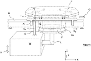
- FIG. 1 shows the essential components of a conveyor device according to the invention in a simplified perspective view.
- a carrier T is movable in a conveyor direction G along a stationary conveyor element M designed as a rail.
- the carrier T carries a product holder P, on which products not shown in detail (individually or in groups) can rest in order to move them along a production line.
- the product holder P can be lifted out of the carrier T upwards in the Z direction.
- Driven conveyor links for example drivers, chain links or hooks which can move the carrier T along the conveyor element M are not shown in detail.
- a load cell W shown schematically, is arranged below the conveyor element M.
- the load cell W comprises an angled load introduction section L, which in turn carries a centering unit F which is positioned essentially below the foot E of the product holder P.
- the weight of the product holder P can be introduced into a weighing mechanism (not shown in detail) in the weighing cell W via the load introduction section in order to generate an evaluable weighing signal therefrom.
- All weighing mechanisms known to the person skilled in the art also independent of the present exemplary figures, can be used to generate the weighing signal, the method of electromagnetic force compensation being mentioned in particular.
- the weighing cell W can be moved up and down in a lifting direction H and thus relative to the conveying element M via a lifting mechanism (not shown in detail).
- the stroke direction H coincides with the vertical Z-axis.
- the carrier T in Figure 1 reaches a machining position X B and rests there initially.
- the carrier T must be transferred to a target carrier position which can be precisely predefined in particular by means of its X and Y coordinates. This is necessary in order to be able to ensure that the product holder P is released from the carrier T.
- the device has first alignment means A T which are formed partly on the carrier T and partly on the weighing cell W.
- the carrier T comprises an alignment opening V in the form of a bore, the axis of which runs in the Z direction.
- a cylindrical mandrel D is formed around an axis D Z , which also extends in the Z direction.
- the outside diameter of the mandrel D is slightly smaller than the inside diameter of the alignment opening V.
- the mandrel D is provided with a conical section which facilitates threading into the alignment opening V and at the same time the alignment of the carrier T relative to the mandrel in the XY plane causes.
- the centering unit F has a pyramid section with conically tapering outer surfaces at its upper end. These are part of the second alignment means A P with which the product holder P is released from the carrier T.
- the foot E of the product holder P is open at the bottom and is designed with inner surfaces, not shown in detail, which also belong to the second alignment means A P.
- the spatial arrangement of the load cell W with the mandrel D and the centering unit F is selected so that in an essentially straight, preferably continuous upward movement of the load cell W, the carrier T is first aligned over the mandrel D and then the product holder P is removed from the Carrier T is lifted out so that the product holder P rests on the load introduction section L without force shunting and thus introduces its full weight into the load cell W.
- the arrangement of the mandrel D and the centering unit F to one another thus also determines the position of the carrier T relative to the product holder P at the moment of release.
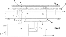
- the alignment or release is illustrated with schematic side views.
- Figure 2 shows how the load cell W is raised in the direction H relative to the conveyor element M with the carrier T resting on it and the product holder P resting thereon.
- the mandrel D is about to engage the alignment opening V of the carrier T.
- the centering unit F is not yet in contact with the foot E of the product holder P.
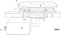
- Figure 4 shows that the balance W has been raised completely in the height direction H.
- the mandrel D has been pushed further through the alignment opening V without further changing the XY position of the carrier.
- the centering unit F has meanwhile completely gripped the foot E of the product holder P and lifted the product holder P out of the carrier T.
- the product holder P thus rests exclusively on the load introduction section L of the weighing cell W, so that the weight of the product holder (with or without the product lying on it) can be recorded by the weighing cell.
- the carrier T is secured in the horizontal direction by the mandrel D during the weighing process, so that during the subsequent downward movement of the weighing cell W (not shown in detail) the product holder P can be reinserted into the carrier T in order to transport it further.
- Figure 5 shows the state according to Figure 4 in a simplified perspective view.
Landscapes
- Engineering & Computer Science (AREA)
- Mechanical Engineering (AREA)
- Physics & Mathematics (AREA)
- General Physics & Mathematics (AREA)
- Specific Conveyance Elements (AREA)
- Sorting Of Articles (AREA)
- Attitude Control For Articles On Conveyors (AREA)
Abstract
Fördereinrichtung und Verfahren zum Transportieren von Produkten, wobei ein Träger mit zugehörigem Produkthalter mittels eines Fördererelements entlang eines Förderwegs bewegbar ist, und wobei der Träger in einer Bearbeitungsposition mittels ersten Ausrichtelementen ausrichtbar ist, und wobei zweite Ausrichtelemente zum Ausrichten des Produkthalters vorgesehen sind.

Description
Die vorliegende Erfindung betrifft eine Fördereinrichtung zum Transportieren von Produkten.The present invention relates to a conveyor for transporting products.
Industrieanlagen zur Herstellung oder Verpackung von Gütern umfassen häufig Förderstrecken, entlang derer die Güter nacheinander zu verschiedenen Bearbeitungsstationen transportiert werden. Zu solchen Bearbeitungsstationen können insbesondere Sortierer, Waagen, Verpackungs- und Inspektionsmaschinen und Kennzeichnungsvorrichtungen zählen. Weitere, dem Fachmann bekannte Vorrichtungen sind ebenfalls denkbar, um die Produkte je nach gewünschter Bearbeitung entsprechend zu behandeln.Industrial plants for the production or packaging of goods often include conveyor lines along which the goods are transported one after the other to different processing stations. Such processing stations can in particular include sorters, scales, packaging and inspection machines and marking devices. Further devices known to the person skilled in the art are also conceivable in order to treat the products accordingly depending on the desired processing.
Die Produkte werden dabei mittels einer Fördereinrichtung zu den einzelnen Bearbeitungsstationen bewegt. Spezielle Förderglieder (Mitnehmer, Haken etc.) werden dabei entlang eines Fördererelements, beispielsweise einer Schiene, in einer Fördereinrichtung bewegt und sind ihrerseits mit einzelnen Trägern koppelbar. Jeder Träger ist zur Aufnahme eines oder mehrerer Produkte ausgebildet. Denkbar ist bspw. ein mit einer Förderkette oder einem Seilzug angetriebener, als Träger dienender Schlitten oder Waagen oder eine Gruppe von Schlitten oder Wagen, mit denen die Produkte mittelbar oder unmittelbar aufgenommen werden, um sie in die einzelnen Bearbeitungsstationen hinein- bzw. wieder heraus zu transportieren.The products are moved to the individual processing stations by means of a conveyor device. Special conveyor members (drivers, hooks, etc.) are moved along a conveyor element, for example a rail, in a conveyor device and, in turn, can be coupled to individual carriers. Each carrier is designed to hold one or more products. Conceivable is, for example, a carriage or scales driven by a conveyor chain or a cable, serving as a carrier, or a group of carriages or carriages with which the products can be picked up directly or indirectly in order to bring them into and out of the individual processing stations transport.
Üblicherweise sind die entlang der Förderstrecke transportierten Träger auf die jeweils zu transportierenden Güter zugeschnitten und weisen besondere Konturen oder Abmaße auf, um die Güter sicher aufnehmen und transportieren zu können. Die Träger können mit den Fördergliedern verbunden werden durch einfaches Einsetzen, Verschrauben, Einrasten etc. Der Träger gestattet es, unterschiedliche Produkte mit derselben Fördereinrichtung zu transportieren, indem bspw. oberer Bereich des Trägers zur Aufnahme unterschiedlicher Produkte ausgebildet ist, während die Unterseite dazu ausgebildet ist, mit den Gliedern einer Vordereinrichtung zu koppeln.Usually, the carriers transported along the conveyor line are tailored to the goods to be transported and have special contours or dimensions in order to be able to safely pick up and transport the goods. The carriers can be connected to the conveyor links by simply inserting, screwing, locking, etc. The carrier allows different products to be transported with the same conveyor, for example by designing the upper area of the carrier to accommodate different products, while the bottom is designed for this to couple with the links of a front device.
Bekannt ist es ferner, bestimmte Produkthalter für die einzelnen Träger vorzusehen. Die Produkthalter können auf die Träger aufgesetzt oder in diese eingesetzt werden und dienen dazu, das zu transportierende Produkt unmittelbar aufzunehmen. Ein Produkthalter kann beispielsweise zur Auflage von Wurst- oder Käsescheiben ausgebildet sein. Auch Produkthalter zur Aufnahme fließfähiger oder rieselfähiger Produkte sind bekannt.It is also known to provide specific product holders for the individual carriers. The product holders can be placed on or inserted into the carriers and serve to directly pick up the product to be transported. A product holder can be designed, for example, to place slices of sausage or cheese. Product holders for holding flowable or free-flowing products are also known.
Die Träger haben vorwiegend die Aufgabe des Gütertransports entlang der Förderstrecke, ohne dass besondere Anforderungen an die hochgenaue Positionierung der Träger während des Transports oder auch an den einzelnen Bearbeitungsstationen bestehen. In der Regel reicht es aus, die von den Trägern transportierten Güter in den einzelnen Bearbeitungsstationen innerhalb vorgebbarer grober Toleranzen zu positionieren, um die Produkte dort bspw. verpacken oder zu Prüfungszwecken durchstrahlen zu können. Werden die Träger bspw. entlang einer Schiene transportiert, so genügt in der Regel in den einzelnen Bearbeitungsstationen die Positioniergenauigkeit, die sich aus der Kopplung zwischen Schiene und dem Träger ergibt. Positionierungenauigkeiten können sich dabei ergeben durch ein bestehendes mechanisches Spiel quer zur Förderrichtung (im weiteren "Y-Richtung") zwischen Schiene und Träger. Auch in Förderrichtung (im weiteren "X-Richtung") können Positioniertoleranzen auftreten, etwa wenn die Träger von einer spielbehafteten Kette, einem Getriebe oder einer Spindel angetrieben werden. Für eine Reihe von Bearbeitungsstationen sind solche Positioniertoleranzen akzeptabel.The main task of the carriers is to transport goods along the conveyor line, without any special requirements for the highly precise positioning of the carriers during transport or at the individual processing stations. As a rule, it is sufficient to position the goods transported by the carriers in the individual processing stations within predeterminable rough tolerances in order to be able to pack the products there, for example, or to be able to irradiate them for testing purposes. If the carriers are transported, for example, along a rail, the positioning accuracy that results from the coupling between the rail and the carrier is usually sufficient in the individual processing stations. Positioning inaccuracies can result from an existing mechanical play perpendicular to the conveying direction (hereinafter "Y-direction") between the rail and the carrier. Positioning tolerances can also occur in the conveying direction (hereinafter "X-direction"), for example when the carriers are driven by a chain with play, a gear or a spindle. Such positioning tolerances are acceptable for a number of machining stations.
Schwierigkeiten treten aber dann auf, wenn die Produkte in einer Bearbeitungsstation sehr genau im Raum positioniert werden müssen. Dies gilt bspw. für eine als Waage ausgeführte Bearbeitungsstation, mit der das Gewicht der von den Trägern transportierten Güter erfasst werden soll. Um ein Produkt in einer als Waage ausgebildeten Bearbeitungsstation wiegen zu können, ist es zweckmäßig, das Produkt (ggf. gemeinsam mit einer bekannten Vorlast) "freizustellen". Darunter wird der Zustand verstanden, in dem die Gewichtskraft des Produkts (ggfls. mit Vorlast) vollständig in den Lastaufnehmer einer Wägezelle der Waage eingeleitet wird, ohne dass eine form- oder kraftschlüssige Verbindung des Produktes zu einer nicht mitzuwiegenden Komponente bestehen bleibt.Difficulties arise, however, when the products have to be positioned very precisely in space in a processing station. This applies, for example, to a processing station designed as a scale, with which the weight of the goods transported by the carriers is to be recorded. In order to be able to weigh a product in a processing station designed as a scale, it is expedient to "release" the product (possibly together with a known preload). This is understood to mean the state in which the weight of the product (possibly with preload) is completely introduced into the load receptor of a load cell of the scale without a positive or non-positive connection between the product and a component that is not to be weighed.
Der vom Träger aufgenommene Produkthalter bildet in der Praxis häufig Vorlast, wird also gemeinsam mit dem Produkt gewogen. Daher muss der Produkthalter zum Wiegen vollständig von dem ihm zugeordneten Träger entkoppelt ("freigestellt") werden, um einen Kraftnebenschluss und damit ein verfälschtes Wägeergebnis zu vermeiden.The product holder picked up by the carrier often forms a preload in practice, that is, it is weighed together with the product. The product holder must therefore be completely decoupled ("released") from the carrier assigned to it for weighing in order to avoid a force shunt and thus a falsified weighing result.
Um die Freistellung des Produkthalters vom Träger sicher zu erreichen, muss zunächst die Position des Trägers im Raum, insbesondere in der X-Y-Ebene, innerhalb enger Toleranzen vorgegeben oder bekannt sein, damit bei der anschließenden Freistellung der Produkthalter möglichst zentrisch aus dem Träger herausgehoben werden kann, ohne dabei zu verkippen oder zu verrutschen. Nur dann kann die Freistellung durch eine möglichst einfache, kleine und schnelle Relativbewegung zwischen dem Träger und dem Produkthalter erreicht werden. Die groben Toleranzen, mit denen aus dem Stand der Technik bekannte Träger entlang der Förderstrecke bewegt werden, sind daher ungeeignet, um die mit den Trägern transportierten Produkthalter ausreichend genau auszurichten.In order to safely release the product holder from the carrier, the position of the carrier in space, in particular in the XY plane, must first be specified or known within narrow tolerances so that the product holder can be lifted out of the carrier as centrally as possible during the subsequent release without tilting or slipping. Only then can the release be achieved by a relatively simple, small and fast relative movement between the carrier and the product holder. The rough tolerances with which carriers known from the prior art are moved along the conveying path are therefore unsuitable for aligning the product holders transported with the carriers with sufficient accuracy.
Aufgabe der Erfindung war es daher, eine Vorrichtung und ein Verfahren anzubieten, mit dem die Träger soweit genau ausgerichtet werden können, dass eine anschließende Freistellung des Produkthalters relativ zum Träger einfach und schnell möglich ist. Die Aufgabe wird gelöst durch eine Fördereinrichtung nach Anspruch 1 und ein Verfahren nach Anspruch 16. Weitere vorteilhafte Ausführungsformen ergeben sich aus den Unteransprüchen.The object of the invention was therefore to offer a device and a method with which the carriers can be aligned precisely to the extent that a subsequent release of the product holder relative to the carrier is easily and quickly possible. The object is achieved by a conveyor device according to
Die Erfindung basiert auf der Erkenntnis, einen entlang einer Fördereinrichtung transportierten Träger in einer Bearbeitungsposition mit Hilfe von speziellen Ausrichtmitteln möglichst genau vorpositionieren zu können, sodass das anschließende Freistellen durch einfache Relativbewegung zwischen Träger und Produkthalter möglich wird, vorzugsweise durch eine nur eindimensionale Bewegung.The invention is based on the knowledge of being able to preposition a carrier transported along a conveyor device in a processing position as precisely as possible with the help of special alignment means, so that the subsequent release is possible by a simple relative movement between the carrier and the product holder, preferably by only one-dimensional movement.
Die zum Ausrichten des Trägers erfindungsgemäß vorgesehenen ersten Ausrichtmittel sind so konfiguriert, dass sie einen in einer Bearbeitungsposition entlang der Förderstrecke eingetroffenen Träger in eine vorgebbare Trägersolllage überführen können. Dies geschieht durch Beaufschlagung und Bewegung des Trägers relativ zur Förderereinrichtung oder einer anderen Komponente, die zumindest bezüglich ihrer horizontalen Anordnung im Raum ortsfest ist. Zusätzlich zu der nur groben Positionierung, die der Träger über seine Kopplung an die Komponenten der Fördereinrichtung erfährt, gewährleisten die erfindungsgemäßen ersten Ausrichtmittel die Überführung des in der Bearbeitungsposition eingetroffenen Trägers in die genau vorgebbare Trägersolllage. Der Träger kann so, relativ zur Fördereinrichtung oder einer mit dieser verbundenen Komponente, verschoben und/oder verkippt werden, um das anschließende Freistellen des von dem Träger aufgenommenen Produkthalters auf einfache Weise zu ermöglichen. Vorzugsweise ist die Kopplung zwischen der Fördereinrichtung und dem Träger innerhalb grober Toleranzen so gewählt, dass sich die durch die ersten Ausrichtmittel bewirkte genaue Ausrichtung des Trägers innerhalb dieser Toleranzen bewegt.The first alignment means provided according to the invention for aligning the carrier are configured in such a way that they can transfer a carrier that has arrived in a processing position along the conveying path into a predetermined carrier target position. This is done by loading and moving the carrier relative to the conveyor device or another component, at least with respect to its horizontal Arrangement in the room is stationary. In addition to the only rough positioning that the carrier experiences via its coupling to the components of the conveying device, the first alignment means according to the invention ensure the transfer of the carrier that has arrived in the processing position into the precisely specifiable target carrier position. The carrier can thus be displaced and / or tilted relative to the conveying device or a component connected to it, in order to enable the subsequent exposure of the product holder received by the carrier in a simple manner. The coupling between the conveying device and the carrier is preferably selected within rough tolerances in such a way that the precise alignment of the carrier effected by the first alignment means moves within these tolerances.
Zweckmäßigerweise umfassen die ersten Ausrichtmittel, die zumindest teilweise beweglich ausgebildet sind, wenigstens ein verfahrbares Ausrichtelement. Mit diesem lässt sich der Träger nach Erreichen der Bearbeitungsposition zum Ausrichten beaufschlagen und verschieben oder verkippen. Das Ausrichterelement weist zweckmäßigerweise Kontaktflächen auf, die bei Bewegung des Ausrichteelements relativ zum Träger mit diesem in Eingriff gelangen und bei weiterer Fortführung der Bewegung auf den Träger Kräfte ausüben, um diesen in die gewünschte Trägersollposition zu verschieben und/oder zu verkippen.The first alignment means, which are designed to be at least partially movable, expediently comprise at least one displaceable alignment element. With this, the carrier can be loaded and shifted or tilted for alignment after reaching the processing position. The alignment element expediently has contact surfaces which, when the alignment element moves relative to the carrier, come into engagement with the carrier and, when the movement continues, exert forces on the carrier in order to move and / or tilt the carrier into the desired target position.
Die Bewegung der ersten Ausrichtmittel relativ zum Träger kann beispielsweise durch einen Linearantrieb oder andere, dem Fachmann bekannte elektromechanische Antriebsmittel erfolgen. Die Ausrichtung kann auch unter Nutzung der Bewegung des Trägers entlang des Förderweges geschehen, etwa indem der Träger durch seitliche Führungsmittel beaufschlagt wird, während er sich in die Bearbeitungsposition hinein bewegt. Die genaue Ausrichtung des Trägers in X-Richtung kann beispielsweise durch einen in den Förderweg hineinschwenkbaren Anschlag an der Bearbeitungsposition erreicht werden. Nach Erreichen des Anschlags ist der Träger aufgrund der seitlichen Führungsmittel auch in Y-Richtung genau positioniert. Eine alternative, nachfolgend bevorzugte Ausführungsform sieht dagegen vor, dass die ersten Ausrichtmittel erst dann mit dem Träger zusammenwirken, wenn dieser die Bearbeitungsposition erreicht hat und dort bereits verharrt. In diesem Fall ist die Bearbeitungsposition nur innerhalb grober Toleranzen definiert, und der Träger kann insbesondere in X-und in Y-Richtung noch verschoben werden.The movement of the first alignment means relative to the carrier can take place, for example, by a linear drive or other electromechanical drive means known to those skilled in the art. The alignment can also take place using the movement of the carrier along the conveying path, for example in that the carrier is acted upon by lateral guide means while it is moving into the processing position. The exact alignment of the carrier in the X direction can be achieved, for example, by a stop at the processing position that can be pivoted into the conveying path. After the stop has been reached, the carrier is also precisely positioned in the Y direction due to the lateral guide means. An alternative, preferred embodiment below, however, provides that the first alignment means only interact with the carrier when the carrier has reached the processing position and has already stopped there. In this case, the machining position is only defined within rough tolerances, and the carrier can still be displaced in particular in the X and Y directions.
Eine vorteilhafte Ausführungsformen der Erfindung sieht vor, dass die ersten Ausrichtmittel wenigstens einen um eine Längsachse ausgebildeten Dorn umfassen, der zur Ausrichtung des Trägers gegen eine Führungsfläche am Träger, vorzugsweise in eine Ausnehmung oder in eine Öffnung bzw. Bohrung des Trägers hineinbewegbar ist. Der Dorn und die mit ihm zusammen wirkenden Führungsflächen am Träger sind so gestaltet, dass eine Bewegung des Dorn in einer ersten Richtung (insbesondere in einer zur X-Y-Ebene senkrechten Richtung Z) den Träger gleichzeitig in den beiden zur Z-Richtung senkrechten Richtungen X und Y ausrichtet. Dies kann vorteilhaft erreicht werden durch eine kegelförmige Spitze des Dorns, die in die Ausnehmung des Trägers eingeführt wird, wobei die Kegelfläche sich mit zunehmender Z-Höhe an die Kontaktflächen der Ausnehmung des Trägers bis zur Kontaktierung annähert, um daran anschließend horizontale Verschiebekräfte von der Kegelfläche des Dorns auf die Kontaktflächen des Trägers auszuüben und diesen entsprechend zu verschieben. Vorzugsweise ist der Dorn bezüglich seiner X-und Y-Position dabei ortsfest, während der Träger in der X-Y-Ebene, also auch relativ zur Fördereinrichtung, um das erforderliche Maß verschiedentlich und somit ausrichtbar ist. Mehrere, zueinander beanstandete Dorne oder vergleichbare Ausrichtelemente können die Ausrichtung des Trägers noch vereinfachen, da so auch eine bestimmte Drehlage in der X-Y-Ebene vorgebbar ist.An advantageous embodiment of the invention provides that the first alignment means comprise at least one mandrel formed around a longitudinal axis, which can be moved into a recess or into an opening or bore of the carrier for aligning the carrier against a guide surface on the carrier. The mandrel and the guide surfaces on the carrier that interact with it are designed so that a movement of the mandrel in a first direction (in particular in a direction Z perpendicular to the XY plane) simultaneously moves the carrier in the two directions X and perpendicular to the Z direction Y aligns. This can advantageously be achieved by a conical tip of the mandrel, which is inserted into the recess of the carrier, the conical surface approaching the contact surfaces of the recess of the carrier with increasing Z-height until contact is made, in order to then generate horizontal displacement forces from the conical surface exercise the mandrel on the contact surfaces of the carrier and move it accordingly. The mandrel is preferably stationary with respect to its X and Y position, while the carrier can be aligned differently and thus in various ways in the X-Y plane, ie also relative to the conveying device. Several mandrels spaced apart from one another or comparable alignment elements can still simplify the alignment of the carrier, since in this way a certain rotational position in the X-Y plane can also be specified.
Eine vorteilhafte Ausführungsform der Erfindung sieht weiterhin vor, dass zweite Ausrichtmittel vorgesehen sind, um den Produkthalter relativ zum Träger in eine vorgebbare Produkthaltersolllage zu überführen (freizustellen), die zumindest hinsichtlich ihrer X- und Y-Position definiert ist. Damit ist es erfindungsgemäß möglich, nach vorheriger Ausrichtung des Trägers im Raum nun den Produkthalter vom Träger freizustellen, um den Wiegevorgang durchzuführen.An advantageous embodiment of the invention further provides that second alignment means are provided in order to transfer (release) the product holder relative to the carrier in a predeterminable target product holder position, which is defined at least with regard to its X and Y position. It is thus possible according to the invention, after the carrier has been previously aligned in space, to release the product holder from the carrier in order to carry out the weighing process.
Während die ersten Ausrichtmitteln dazu dienen, den nicht mitzuwiegenden Träger der Fördereinrichtung für die spätere Freistellung des Produkthalters genau im Raum auszurichten, dienen die zweiten Ausrichtmitteln bevorzugt dazu, den Produkthalter relativ zum Träger freizustellen. Alternativ kann es jedoch auch genügen, lediglich die zweiten Ausrichtmittel für die vollständige Freistellung des Produkthalters im Träger zu betätigen, wenn die nur innerhalb grober Toleranzen vom Träger eingenommene Bearbeitungsposition jedenfalls dazu ausreicht, die Freistellung des Produkthalters vom Träger sicher zu bewirken.While the first alignment means serve to align the carrier of the conveying device that is not to be weighed exactly in space for the later release of the product holder, the second alignment means preferably serve to release the product holder relative to the carrier. Alternatively, however, it can also suffice to actuate only the second alignment means for the complete release of the product holder in the carrier, if the processing position assumed by the carrier only within rough tolerances is sufficient to reliably release the product holder from the carrier.
Zweckmäßigerweise sind an dem Produkthalter Ausrichtflächen oder -konturen vorgesehen, die zur Wechselwirkung mit einer relativ zum Produkthalter bewegten Zentriereinheit ausgebildet sind. Zentriereinheit und Ausrichtungsflächen bilden gemeinsam die zweiten Ausrichtmittel. Die zweiten Ausrichtmittel können analog zu den ersten Ausrichtmitteln so ausgebildet sein, dass sich im Rahmen einer Relativbewegung zwischen Zentriereinheit und Produkthalter Kontaktflächen beider Komponenten einander annähern bzw. berühren, um insbesondere in der X-Y-Ebene Kräfte auf den Produkthalter auszuüben und ihn auszurichten. Bspw. könnte der Produkthalter an einer dem Träger zugewandten Seite mit konisch verlaufenden Flächen versehen sein, die mit geeigneten Führungsflächen oder -kanten des Trägers zusammenwirken und so den Produkthalter im Träger relativ zu diesem genau positionieren.Alignment surfaces or contours are expediently provided on the product holder which are designed to interact with a centering unit that is moved relative to the product holder. Centering unit and alignment surfaces together form the second alignment means. The second alignment means can be designed analogously to the first alignment means so that contact surfaces of both components approach or touch each other during a relative movement between the centering unit and the product holder, in order to exert forces on the product holder and to align it, in particular in the X-Y plane. E.g. For example, the product holder could be provided on a side facing the carrier with conically running surfaces which interact with suitable guide surfaces or edges of the carrier and thus precisely position the product holder in the carrier relative to the carrier.
Alternativ ist es jedoch auch denkbar, die zweiten Ausrichtelemente lediglich als gegeneinander wirkende Anschlagelemente auszubilden, die dazu verwendet werden, den Produkthalter aus dem Träger herauszuheben. Ist der Produkthalter dabei so im Träger angeordnet, dass durch vertikales Herausheben des Produkthalters aus dem Träger zugleich eine mechanische Trennung des Produkthalters vom Träger erreicht wird, so genügt dies bereits zum Freistellen. Die Zentriereinheit dient in diesem Fall nicht zum Zentrieren (also zum horizontalen Ausrichten des Produkthalters relativ zur Zentriereinheit), sondern lediglich zum Anheben des Produkthalters in Z-Richtung, ohne dass die Position des Produkthalters im Raum in X-oder Y-Richtung verändert wird.Alternatively, however, it is also conceivable to design the second alignment elements merely as stop elements which act against one another and which are used to lift the product holder out of the carrier. If the product holder is arranged in the carrier in such a way that, by lifting the product holder vertically out of the carrier, a mechanical separation of the product holder from the carrier is achieved at the same time, then this is sufficient for the release. In this case, the centering unit is not used for centering (i.e. for horizontal alignment of the product holder relative to the centering unit), but only for lifting the product holder in the Z direction without changing the spatial position of the product holder in the X or Y direction.
Eine vorteilhafte Ausführungsform der Erfindung sieht weiterhin vor, dass die Fördereinrichtung eine Wägezelle umfasst, die zur Gewichtserfassung eines mit Produkt beladenen oder unbeladenen, in der Bearbeitungsposition von seinem zugehörigen Träger freigestellten Produkthalters ausgebildet ist, wobei die Wägezelle einen die Zentriereinheit umfassenden Lasteinleitungsabschnitt zur Einleitung der zu wiegenden Last in die Wägezelle aufweist. Die Wägezelle hat die Aufgabe, die entlang des Förderweges transportierten Produkte zu wiegen. Dazu müssen die die Produkte aufnehmenden Produkthalter in der zuvor beschriebenen Weise freigestellt werden. Die zu ermittelnde Gewichtskraft wird vom Produkthalter in den Lasteinleitungsabschnitt der Wägezelle eingeleitet und über einen dem Fachmann bekannten Mechanismus innerhalb der Wägezelle in ein auswertbares Signal umgewandelt.An advantageous embodiment of the invention further provides that the conveying device comprises a weighing cell which is designed to record the weight of a product holder loaded or unloaded with product and released from its associated carrier in the processing position, the weighing cell having a load introduction section comprising the centering unit for introducing the to weighing load in the load cell. The load cell has the task of weighing the products transported along the conveyor route. For this purpose, the product holders receiving the products must be released in the manner described above. The weight force to be determined is introduced by the product holder into the load application section of the weighing cell and converted into an evaluable signal within the weighing cell via a mechanism known to those skilled in the art.
Vorzugsweise umfasst der Lasteinleitungsabschnitt die Zentriereinheit, mit welcher der Produkthalter relativ zum Träger freigestellt wird. Die Freistellung des Produkthalters erfolgt dann, indem zunächst der Träger durch die ersten Ausrichtmittel im Raum ausgerichtet wird. Im Rahmen dieser Ausrichtung wird der Träger (mit dem von ihm aufgenommenen Produkthalter) in der Bearbeitungsposition so ausgerichtet, dass der Produkthalter für den nachfolgenden Freistellungsvorgang so relativ zur Zentriereinheit positioniert wird, dass die Freistellung alleine mithilfe einer Relativbewegung zwischen Zentriereinheit und Produkthalter erfolgen kann. Dabei ist die Wägezelle mit ihrem die Zentriereinheit umfassende Lasteinleitungsabschnitt soweit verschieblich ausgebildet, dass die Gewichtskraft des Produkthalters kraftnebenschlussfrei in den Lasteinleitungsabschnitt eingeleitet (Freistellung) oder davon entkoppelt (der Produkthalter ruht auf dem Träger) wird.The load introduction section preferably comprises the centering unit with which the product holder is exposed relative to the carrier. The product holder is then released by first aligning the carrier in space using the first alignment means. As part of this alignment, the carrier (with the product holder it has received) is aligned in the processing position in such a way that the product holder for the subsequent release process is positioned relative to the centering unit so that the release can take place solely with the aid of a relative movement between the centering unit and product holder. The load cell with its load introduction section including the centering unit is designed to be displaceable to such an extent that the weight of the product holder is introduced into the load introduction section without force shunting (release) or is decoupled from it (the product holder rests on the carrier).
Der Vorgang des Freistellens kann vorzugsweise so erfolgen, dass die Wägezelle mit ihrem Lasteinleitungsabschnitt und der daran angeordneten Zentriereinheit relativ zum Produkthalter auf diesen zubewegt wird, um den Produkthalter dadurch aufzunehmen und aus dem Träger herauszulösen. Zweckmäßigerweise ist die Wägezelle dazu an einer Hubvorrichtung angeordnet, sodass sie mit ihrem Lasteinleitungsabschnitt (vorzugsweise von unten) aufwärts gegen den Produkthalter verfahrbar ist, um diesen aus dem Träger herauszuheben. Im umgekehrten Bewegungsablauf senkt sich die Wägezelle wieder herab, sodass der Produkthalter wieder vom Träger aufgenommen wird. Sobald die Zentriereinheit ausreichend weit vom Produkthalter getrennt ist und erforderlichenfalls auch die ersten Ausrichtungsmittel vom Träger gelöst wurden, kann der Träger mitsamt Produkthalter entlang des Förderweges zur nächsten Bearbeitungsstation verfahren werden.The process of releasing can preferably take place in such a way that the load cell with its load introduction section and the centering unit arranged thereon is moved towards the product holder relative to the latter, in order to thereby receive the product holder and detach it from the carrier. For this purpose, the weighing cell is expediently arranged on a lifting device so that its load introduction section (preferably from below) can be moved upwards against the product holder in order to lift it out of the carrier. In the reverse sequence of movements, the load cell is lowered again so that the product holder is picked up again by the carrier. As soon as the centering unit is separated sufficiently from the product holder and, if necessary, the first alignment means have also been released from the carrier, the carrier together with the product holder can be moved along the conveying path to the next processing station.
Alternativ könnte der Produkthalter auch auf eine im Wesentlichen ortsfeste Wägezelle abgesenkt werden. Dies hätte jedoch zur Folge, dass mit dem Produkthalter auch der diesen tragende Träger abgesenkt werden müsste, was konstruktiv schwierig, aber nicht unmöglich ist.Alternatively, the product holder could also be lowered onto an essentially stationary load cell. However, this would mean that the carrier carrying the product would also have to be lowered with the product holder, which is structurally difficult, but not impossible.
Nach einer vorteilhaften Ausführungsform der Erfindung ist die Fördereinrichtung so ausgebildet, dass die Freistellung bewirkt wird durch Ausrichtung des Trägers im Raum mittels erster Ausrichtelemente mit anschließender oder zeitlich überschneidender oder zeitgleicher Ausrichtung bzw. Freistellung des Produkthalters relativ zum Träger mittels der zweiten Ausrichtelemente. Eine besonders bevorzugte Ausführungsform sieht dabei vor, dass ein Teil der ersten Ausrichtelemente (insbesondere der vorgenannte Dorn) mit der Wägezelle starr oder weitgehend starr gekoppelt ist, so dass diese Ausrichtelemente durch vorzugsweise vertikales Verfahren der Wägezelle mit dem auszurichtenden Träger in Eingriff gelangen und diesen ausrichten bzw. in die Trägersollposition überführen. In diesem Fall sind sowohl Teile der ersten Ausrichtmittel (beispielsweise der Dorn), als auch Teile der zweiten Ausrichtmittel (nämlich die Zentriereinheit) an der Wägezelle angeordnet. Durch ein insbesondere vertikales Anheben oder Absenken der Wägezelle wirken somit die ersten Ausrichtmittelmit dem Träger zusammen, um diesen im Raum auszurichten, während gleichzeitig oder zeitversetzt die Zentriereinheit mit dem Produkthalter zusammenwirkt, um diesen aus dem Träger herauszuheben.According to an advantageous embodiment of the invention, the conveying device is designed such that the release is effected by aligning the carrier in space by means of first alignment elements with subsequent or temporally overlapping or simultaneous alignment or exposure of the product holder relative to the carrier by means of the second alignment elements. A particularly preferred embodiment provides that some of the first alignment elements (in particular the aforementioned mandrel) are rigidly or largely rigidly coupled to the load cell, so that these alignment elements come into engagement with the carrier to be aligned and align it by preferably moving the load cell vertically or transfer it to the desired carrier position. In this case, both parts of the first alignment means (for example the mandrel) and parts of the second alignment means (namely the centering unit) are arranged on the weighing cell. By raising or lowering the weighing cell, in particular vertically, the first alignment means cooperate with the carrier in order to align it in space, while at the same time or with a time offset the centering unit cooperates with the product holder in order to lift it out of the carrier.
Die Ausrichtung des den Produkthalter tragenden Trägers im Raum bzw. relativ zur X-Y-Position der Wägezelle ist wichtig, um die Gewichtskraft des Produkthalters (mit oder ohne aufliegenden Produkten) beim späteren Freistellen genau und störungsfrei in den Lasteinleitungsabschnitt der Wägezelle einleiten zu können. Zur Vermeidung von Ecklasten wird daher angestrebt, den Lasteinleitungsabschnitt im Rahmen der Freistellbewegung gegen einen genau definierten Kopplungsabschnitt des Produkthalters zu bewegen. Durch die vorherige genaue Ausrichtung des Trägers mit den ersten Ausrichtmittel wird sichergestellt, dass der Lasteinleitungsabschnitt an dem vorgesehenen Kopplungsabschnitt mit dem Produkthalter zusammenwirkt und nicht etwa seitlich dazu beabstandet ist.The alignment of the carrier carrying the product holder in space or relative to the X-Y position of the load cell is important in order to be able to introduce the weight of the product holder (with or without products on top) into the load application section of the load cell precisely and without interference when it is later released. In order to avoid corner loads, the aim is therefore to move the load introduction section within the framework of the release movement against a precisely defined coupling section of the product holder. The previous precise alignment of the carrier with the first alignment means ensures that the load introduction section interacts with the product holder at the coupling section provided and is not laterally spaced from it.
Die Kopplung des Produkthalters mit dem Lasteinleitungsabschnitt zum Zwecke des Freistellens erfolgt vorzugsweise so, dass der Produkthalter auf dem Lasteinleitungsabschnitt lediglich lose aufliegt. Durch vertikale Relativbewegung zwischen Lasteinleitungsabschnitt und Produkthalter lassen sich dann diese beiden Komponenten zur Übertragung der Gewichtskraft miteinander koppeln bzw. zur Lösung der Gewichtskraft voneinander entkoppeln.The coupling of the product holder to the load introduction section for the purpose of releasing is preferably carried out in such a way that the product holder only rests loosely on the load introduction section. By means of a vertical relative movement between the load introduction section and the product holder, these two components can then be coupled to one another for transferring the weight force or decoupled from one another in order to release the weight force.
Eine besonders bevorzugte Ausführungsform der Vorrichtung sieht vor, dass die Ausrichtung des Trägers im Raum und die Freistellung des Produkthalters relativ zum Träger im Rahmen einer (vorzugsweise kontinuierlichen) Relativbewegung zwischen Wägezelle und Träger erreicht wird. Dabei kann die Wägezelle mit einem als Teil der an ihr befestigten oder gemeinsam mit ihr bewegten ersten Ausrichtmittel, bevorzugt mit einem Dorn, von unten in Z-Richtung auf einen in einer Bearbeitungsposition angeordneten Träger zubewegt werden. Dieser Teil der ersten Ausrichtmittel gelangt bei der Aufwärtsbewegung in Kontakt mit weiteren Teilen der ersten Ausrichtmittel, die am Träger angeordnet sind. Im Rahmen der Aufwärtsbewegung wird der Träger durch diesen Kontakt relativ zur Wägezelle in X-und Y-Richtung ausgerichtet. Bevorzugt ist als Teil der Ausrichtmittel an der Wägezelle ein Dorn befestigt, der in eine im Träger ausgebildete Ausnehmung eingreifen kann, sodass der Träger in der vorstehend beschriebenen Weise relativ zur Wägezelle und damit im Raum ausgerichtet wird.A particularly preferred embodiment of the device provides that the orientation of the carrier in space and the exposure of the product holder relative to the carrier is achieved within the framework of a (preferably continuous) relative movement between the load cell and the carrier. The weighing cell can be moved from below in the Z-direction towards a carrier arranged in a processing position with a first alignment means attached to it or moved together with it, preferably with a mandrel. During the upward movement, this part of the first alignment means comes into contact with further parts of the first alignment means which are arranged on the carrier. During the upward movement, this contact aligns the carrier relative to the load cell in the X and Y directions. As part of the alignment means, a mandrel is preferably attached to the load cell, which pin can engage in a recess formed in the carrier so that the carrier is aligned relative to the load cell and thus in space in the manner described above.
In der weiteren Aufwärtsbewegung gleitet der Dorn ohne zusätzliche Wechselwirkung mit dem Träger durch die genannte Ausnehmung weiter aufwärts, während sich die am Lasteinleitungsabschnitt der Wägezelle angeordnete Zentriereinheit von unten auf den im Träger angeordneten Produkthalter zubewegt. Die Zentriereinheit untergreift den Produkthalter und richtet diesen in der weiteren Aufwärtsbewegung der Wägezelle (erforderlichenfalls mithilfe geeigneter Führungsflächen) relativ zum Träger so aus, dass der Produkthalter aus dem Träger herausgehoben und von ihm freigestellt wird. Da die Ausrichtung des Trägers und anschließend die Freistellung des Produkthalters im Rahmen einer einzigen Bewegung der Wägezelle relativ zum Träger erfolgen kann, kann das in die Bearbeitungsstation überbrachte Produkt zügig gewogen werden. Auch die Freigabe des Produkts zum Weitertransport, also das Absenken der Wägezelle zum Wiedereinsetzung des Produkthalters in den Träger und die anschließende Freigabe des Trägers (Entkopplung der ersten) Ausrichtmittel, kann über eine einzige, diesmal entgegengesetzte Relativbewegung zwischen Wägezelle und Träger erfolgen und den Bearbeitungsprozess vorteilhaft beschleunigen.In the further upward movement, the mandrel slides further upward through the said recess without additional interaction with the carrier, while the centering unit arranged on the load introduction section of the weighing cell moves from below towards the product holder arranged in the carrier. The centering unit engages under the product holder and aligns it in the further upward movement of the weighing cell (if necessary with the aid of suitable guide surfaces) relative to the carrier so that the product holder is lifted out of the carrier and released from it. Since the alignment of the carrier and then the release of the product holder can take place in the context of a single movement of the weighing cell relative to the carrier, the product brought into the processing station can be weighed quickly. The release of the product for further transport, i.e. the lowering of the load cell to reinsert the product holder in the carrier and the subsequent release of the carrier (decoupling of the first alignment means) can also take place via a single, this time opposite, relative movement between the load cell and the carrier and the processing process is advantageous accelerate.
Die Relativbewegung zwischen Wägezelle und Träger erfolgt vorzugsweise linear, also entlang eines geraden Weges. Bei geeigneter Gestaltung der ersten und zweiten Ausrichtelemente ist jedoch auch ein gekrümmter oder in sonstiger Weise geeigneter räumlicher Weg denkbar, entlang dessen die Wägezelle relativ zum Träger bewegt wird, um die Ausrichtung und Freistellung zu bewirken.The relative movement between the load cell and the carrier is preferably linear, that is, along a straight path. With a suitable design of the first and second alignment elements, however, a curved or otherwise suitable spatial path is also conceivable, along which the weighing cell is moved relative to the carrier in order to effect the alignment and release.
Nach einer vorteilhaften Ausführungsform umfasst die Fördereinrichtung mehrere Träger, wobei jeder Träger ein oder mehrere Produkthalter aufnehmen kann. Bevorzugt sind die Träger und/oder ihre Produkthalter mit einer Kennung versehen sind, aus der bspw. die geometrischen Eigenschaften des jeweiligen Trägers bzw. Produkthalters herleitbar sind, beispielsweise über eine Steuereinheit mit Zugriff auf eine Datenbank. Wird die Kennung der Träger bzw. Produkthalter durch geeignete Sensoren entlang der Förderstrecke automatisch ausgelesen, so lässt sich ein automatisierter Ausrichtungsvorgang darauf einstellen. Dies kann beispielsweise den gewünschten Hub der Wägezelle bzw. eines Pneumatikzylinders oder eines Linearantriebs betreffen, um je nach konstruktiver Gestaltung des Trägers oder des Produkthalters die erforderliche Hubhöhe zum Ausrichten bzw. Freistellen festlegen zu können.According to an advantageous embodiment, the conveyor device comprises several carriers, each carrier being able to accommodate one or more product holders. The carriers and / or their product holders are preferably provided with an identifier from which, for example, the geometric properties of the respective carrier or product holder can be derived, for example via a control unit with access to a database. If the identification of the carrier or product holder is automatically read out by suitable sensors along the conveying path, an automated alignment process can be set accordingly. This can relate, for example, to the desired stroke of the weighing cell or a pneumatic cylinder or a linear drive in order to be able to determine the necessary stroke height for alignment or freeing, depending on the structural design of the carrier or the product holder.
Nach einer vorteilhaften Ausführungsform der Erfindung sind mehrere Träger gemeinsam entlang des Förderweges bewegbar. Dadurch lassen sich mehrere Produkthalter, die jeweils einem der Träger zugeordnet sind, gleichzeitig transportieren, was den Durchsatz der Anlage erhöht. Durch geeignete Anordnung mehrerer Wägezellen in einer zum Wiegen eingerichteten Bearbeitungsstation können so auch gleichzeitig mehrere Produkthalter (mit oder ohne aufliegendes Produkt) gewogen werden. Die für einen Träger vorstehend beschriebenen Merkmale gelten dann entsprechend auch für die anderen Träger. Gelangen die Träger in eine zum Wiegen ausgebildete Bearbeitungsstation, dann ist dort vorzugsweise für jeden Träger oder zumindest für jeden Produkthalter eine eigene Wägezellen mit Lasteinleitungselement vorgesehen, sodass jede Wägezelle das Gewicht des Produkthalters eines der Träger erfassen kann.According to an advantageous embodiment of the invention, several carriers can be moved together along the conveying path. As a result, several product holders, each assigned to one of the carriers, can be transported at the same time, which increases the throughput of the system. With a suitable arrangement of several weighing cells in a processing station set up for weighing, several product holders (with or without a product on top) can be weighed at the same time. The features described above for a carrier then also apply correspondingly to the other carriers. If the carriers reach a processing station designed for weighing, then a separate load cell with load introduction element is preferably provided there for each carrier or at least for each product holder so that each load cell can detect the weight of the product holder of one of the carriers.
Die Relativbewegung zwischen jeweiligem Produkthalter und Lasteinleitungselement bzw. Wägezelle kann erfolgen, indem die Wägezellen gemeinsam auf-oder ab bewegt werden relativ zu den mehreren Produkthaltern in den einzelnen Trägern. Alternativ kann jedoch auch eine individuelle Relativbewegung zwischen jeweiliger Wägezelle und zugehörigem Träger bzw. Produkthalter erfolgen, was die Flexibilität der Verfahrensführung innerhalb der Bearbeitungsstation erhöht.The relative movement between the respective product holder and load application element or load cell can take place in that the load cells are moved up or down together relative to the multiple product holders in the individual carriers. Alternatively, however, an individual relative movement can also take place between the respective weighing cell and the associated carrier or product holder, which increases the flexibility of the process control within the processing station.
Vorzugsweise sind mehrere gemeinsam bewegte Träger in Förderrichtung oder quer dazu nebeneinanderliegend oder in Matrixform in einer Zeilen-und-Spalten-Matrix angeordnet. Auf vergleichsweise engem Raum lassen sich so mehrere Produkthalter schnell wiegen.A plurality of carriers moved together are preferably arranged next to one another in the conveying direction or transversely thereto or in matrix form in a row-and-column matrix. Several product holders can be weighed quickly in a comparatively small space.
Die verschiedenen Träger der Fördereinrichtung und/oder deren Produkthalter sind nach einer vorteilhaften Ausführungsform der Erfindung jeweils mit einer eindeutigen Kennung versehen. Diese Kennung soll es möglich machen, den Träger und/oder den Produkthalter zu identifizieren und zu individualisieren. Dadurch können bestimmte Eigenschaften des Trägers und/oder des Produkthalters erfasst und beispielsweise einer übergeordneten Steuerung übermittelt werden, um diese beim Betrieb der Fördereinrichtung zu berücksichtigen. Dies kann beispielsweise das Leergewicht (Tara) betreffen. Jeder Produkthalter hat ein solches individuelles Leergewicht, welches beim Wiegen zu berücksichtigen ist. Die individuelle Kennung ermöglicht es, das Leergewicht des jeweiligen Produkthalters dafür zu ermitteln. Das Leergewicht kann unmittelbar in der Kennung selbst enthalten sein oder mithilfe der Kennung aus einer Datenbank ermittelt werden, welche den Zusammenhang zwischen der Kennung und dem Leergewicht herstellt.According to an advantageous embodiment of the invention, the various carriers of the conveyor device and / or their product holders are each provided with a unique identifier. This identifier should make it possible to identify and individualize the carrier and / or the product holder. As a result, certain properties of the carrier and / or of the product holder can be recorded and, for example, transmitted to a higher-level controller in order to take them into account when the conveyor is operating. This can, for example, concern the empty weight (tare). Each product holder has such an individual empty weight, which must be taken into account when weighing. The individual identifier makes it possible to determine the empty weight of the respective product holder. The tare weight can be contained directly in the identifier itself or can be determined with the aid of the identifier from a database which establishes the connection between the identifier and the tare weight.
Bei der Kennung kann es sich um unveränderliche Kennzeichnungsmittel handeln, wie bspw. einen Barcode oder eine Nummer oder eine feste RFID-Kennung. Alternativ oder ergänzend kann die Kennung auch veränderlich sein, etwa um bestimmte, möglicherweise auch veränderliche Eigenschaften des Trägers oder Produkthalters unmittelbar in der Kennung zu hinterlegen. Bspw. könnte ein Code für das Leergewicht eines Produkthalters in einem am Produkthalter angeordneten Speicher als Kennung oder Teil einer Kennung hinterlegt werden. Wird die Kennung im Verfahren ausgelesen, so erhält eine das Verfahren steuernde Steuereinheit unmittelbar aus der Kennung Angaben über das Leergewicht des Produkthalters, um dieses beim Wiegen zu berücksichtigen.The identifier can be an unchangeable identifier, such as a barcode or a number or a fixed RFID identifier. Alternatively or in addition, the identifier can also be changeable, for example in order to store specific, possibly also changeable properties of the carrier or product holder directly in the identifier. E.g. a code for the empty weight of a product holder could be stored in a memory arranged on the product holder as an identifier or part of an identifier. If the identifier is read out in the process, a control unit controlling the process receives information about the empty weight of the product holder directly from the identifier in order to take this into account during weighing.
Veränderbare Kennungen haben den Vorteil, dass sie Änderungen des Trägers oder des Produkthalters unmittelbar an der Komponente selbst dokumentieren, ohne dass hierfür eine spezielle Datenbank bearbeitet werden müsste. Wird bspw. das Leergewicht eines (dann unbeladenen) Produkthalters durch einen oder mehrere Wiegevorgänge bestimmt, so kann ein diesen Wert repräsentierender Code unmittelbar in die veränderliche Kennung am Produkthalter geschrieben werden. Im Rahmen eines regulären Wiegeverfahrens mit auf dem Produkthalter aufliegendem Produkt kann durch Auslesen der Kennung das Leergewicht ermittelt und von dem durch die Wägezelle ermittelten Gesamtgewicht abgezogen werden, um das Produktgewicht (netto) zu erhalten.Changeable identifiers have the advantage that they document changes to the carrier or the product holder directly on the component itself, without having to edit a special database for this. If, for example, the empty weight of a (then unloaded) product holder is determined by one or more weighing processes, a code representing this value can be written directly into the variable identifier on the product holder. As part of a regular In the weighing process with the product lying on the product holder, the empty weight can be determined by reading the identifier and subtracted from the total weight determined by the weighing cell in order to obtain the product weight (net).
Alternativ kann das Leergewicht natürlich auch in einer Datenbank hinterlegt werden, aus der die Steuereinheit über die am Produkthalter identifizierte Kennung das Leergewicht zuordnet. Beliebige andere Eigenschaften eines Trägers oder Produkthalters (geometrische Abmessungen, Materialeigenschaften, Zeit- oder Ortsangaben etc.) sind ebenfalls unmittelbar in der Kennung oder einer Datenbank hinterlegbar, welche die Eigenschaften der Kennung zuordnen.Alternatively, the empty weight can of course also be stored in a database from which the control unit assigns the empty weight using the identifier identified on the product holder. Any other properties of a carrier or product holder (geometric dimensions, material properties, time or location information, etc.) can also be stored directly in the identifier or a database, which assign the properties of the identifier.
Denkbar ist es ferner, die Eigenschaften mehrerer Träger und/oder Produkthalter einer gemeinsamen Kennung zuzuordnen, etwa wenn mehrere Träger zu einer Gruppe gekoppelt sind und gemeinsam entlang der Förderstrecke bewegt werden. Dann könnten Eigenschaften der einzelnen Träger und/oder des zu jedem Träger gehörenden Produkthalters in der gemeinsamen Kennung hinterlegt oder dieser zugeordnet sein. Anhand der Kennung soll dann eine Unterscheidung zwischen den einzelnen Trägern bzw. Produkthaltern möglich sein, um die Eigenschaft eines bestimmten Produkthalters oder Trägers innerhalb der Gruppe aus der Kennung auslesen oder herleiten zu können. So könnte eine bspw. aus vier Trägern mit jeweils einem Produkthalter gebildete Gruppe einen gemeinsamen, beschreibbaren RFID-Chip aufweisen. In den Chip sind Daten für jeden Träger und/oder Produkthalter hinterlegbar. Das Auslesen und das Beschreiben eines solchen Speichers werden dann vereinfacht, da nur eine Kennung für alle vier Träger bzw. Produkthalter ausgelesen werden muss. Nur eine Leseeinheit bzw. Beschreibeinheit muss dann vorgesehen werden, um für alle vier Träger oder Produkthalter Daten für eine Steuereinheit auszulesen oder in dem Speicher des RFID -Chips zu hinterlegen. Andere auslesbare und/oder beschreibbare, dem Fachmann hinlänglich bekannte Kennzeichnungsmittel sind ebenfalls denkbar, um einen oder mehrere Träger bzw. Produkthalter zu kennzeichnen und die Zuordnung spezieller Eigenschaften zu ermöglichen.It is also conceivable to assign the properties of several carriers and / or product holders to a common identifier, for example when several carriers are coupled to form a group and are moved together along the conveyor line. Properties of the individual carriers and / or of the product holder belonging to each carrier could then be stored in the common identifier or assigned to this. Using the identifier, it should then be possible to distinguish between the individual carriers or product holders in order to be able to read out or derive the property of a specific product holder or carrier within the group from the identifier. For example, a group formed from four carriers, each with a product holder, could have a common, writable RFID chip. Data for each carrier and / or product holder can be stored in the chip. Reading out and writing to such a memory is then simplified because only one identifier has to be read out for all four carriers or product holders. Only one reading unit or writing unit then has to be provided in order to read out data for a control unit for all four carriers or product holders or to store them in the memory of the RFID chip. Other readable and / or writable marking means that are sufficiently known to the person skilled in the art are also conceivable in order to mark one or more carriers or product holders and to enable the assignment of special properties.
Vorzugsweise ist das Material des Produkthalters zur Röntgendurchstrahlung geeignet. Dann kann der Produkthalter und ein auf dem Produkthalter aufliegendes Produkt mittels Röntgenstrahlen durchstrahlt werden, um darin eventuell enthaltene Fremdkörper detektieren zu können. Auch die Möglichkeit zur Erfassung einer Füllmenge eines Produktes ist dann gegeben, wenn die Intensität der Röntgenstrahlung von der Füllhöhe beeinflusst wird, etwa bei einem auf dem Produkthalter aufliegenden, gefüllten Joghurtbecher. Generell soll der durchstrahlbare Produkthalter es ermöglichen, Füllmengen, Füllhöhen oder Nennfüllmengen mit Hilfe von Röntgendurchstrahlung zu erfassen. Überwachungen des Füllgrads oder Untersuchungen auf möglicherweise im Produkt enthaltene Fremdkörper können in einer entlang der Förderstrecke angeordneten Röntgeninspektionseinheit durchgeführt werden, die stromauf- oder stromabwärts einer als Wägestation ausgebildeten Bearbeitungsstation angeordnet sein kann.The material of the product holder is preferably suitable for x-ray irradiation. Then the product holder and a product lying on the product holder can be by means of X-rays are penetrated in order to be able to detect any foreign bodies contained therein. There is also the possibility of detecting the filling quantity of a product if the intensity of the X-ray radiation is influenced by the filling level, for example in the case of a filled yoghurt cup lying on the product holder. In general, the radiographable product holder should make it possible to record fill quantities, fill levels or nominal fill quantities with the aid of X-ray radiation. Monitoring of the degree of filling or examinations for foreign bodies possibly contained in the product can be carried out in an X-ray inspection unit arranged along the conveyor line, which can be arranged upstream or downstream of a processing station designed as a weighing station.
Vorzugsweise umfasst eine erfindungsgemäße Fördereinrichtung wenigstens eine Wägestation mit wenigstens einer Wägezelle, um in der zuvor beschriebenen Weise Gewichtskräfte zu erfassen.A conveyor device according to the invention preferably comprises at least one weighing station with at least one weighing cell in order to detect weight forces in the manner described above.
Das Verfahren zum Freistellen eines Produkthalters in der zuvor beschriebenen Vorrichtung umfasst mindestens folgende Schritte:
- a) Bewegen eines Trägers mit darin aufgenommenem Produkthalter in die Bearbeitungsposition,
- b) Ausrichten der Trägers mittels erster Ausrichtmittel in eine Trägersolllage,
- c) Relativbewegen (Freistellen) des Produkthalters und des Trägers zueinander, um den Produkthalter vom Träger zu lösen und die Gewichtskraft des mit Produkt beladenen oder unbeladenen Produkthalters in den Lasteinleitungsabschnitt einer Wägezelle einzuleiten.
- a) Moving a carrier with the product holder received therein into the processing position,
- b) aligning the carrier by means of first alignment means in a carrier target position,
- c) Moving the product holder and the carrier relative to one another in order to release the product holder from the carrier and to introduce the weight of the product holder loaded or unloaded with product into the load application section of a load cell.
Vorzugsweise erreicht der Träger die Bearbeitungsposition in einer im wesentlichen horizontalen Bewegung (X-Y-Ebene). Dies schließt jedoch nicht aus, dass diese Bewegung auch eine Z-Komponenten umfasst, etwa wenn der Förderweg aufwärts oder abwärts gerichtet ist. In der Bearbeitungsposition, in der der leere oder ein Produkt tragende Produkthalter gewogen werden soll, ruht der Träger, bezogen auf seine X-und Y- Koordinaten, im wesentlichen ortsfest. Geringe Verschiebemöglichkeiten in X-und/oder Y-Richtung bestehen dennoch, um den Träger mithilfe der ersten Ausrichtmittel bezüglich seiner gewünschten X-Y-Position genau in der vorgebbaren Trägersolllage positionieren zu können.The carrier preferably reaches the processing position in an essentially horizontal movement (XY plane). However, this does not rule out that this movement also includes a Z component, for example when the conveying path is directed upwards or downwards. In the processing position in which the empty product holder or one carrying a product is to be weighed, the carrier rests essentially in a stationary manner in relation to its X and Y coordinates. Slight shifting possibilities in X and / or Y-direction still exist in order to be able to position the carrier with the aid of the first alignment means exactly in the predetermined carrier target position with respect to its desired XY position.
Die Freistellung des Produkthalters relativ zum Träger erfolgt vorzugsweise senkrecht zur X-Y-Ebene durch Herausheben des Produkthalters aus dem Träger. Sie kann der Positionierung des Trägers in der Trägersolllage nachgeschaltet sein. Vorzugsweise überschneiden sich beide Positionierungsvorgänge jedoch, um Zeit zu sparen. Dabei kann die Freistellung des Produkthalters relativ zum Träger sogar bereits abgeschlossen sein, während der Träger noch durch die ersten Ausrichtmittel in die Trägersolllage überführt wird. Denkbar ist es auch, die zweiten Ausrichtmittel am bzw. mit dem Produkthalter bereits in Eingriff zu bringen noch bevor die ersten Ausrichtmittel miteinander wechselwirken. Entsprechend könnte der Produkthalter bereits um ein Maß aus dem Träger herausgehoben werden bevor der Träger seinerseits ausgerichtet wird. Die Freistellung des Produkthalters erfolgt dann spätestens im Rahmen der Überführung des Trägers in die Trägersolllage, da hierdurch die Positionierung des Trägers in X-Y Richtung den ausreichenden seitlichen Abstand zum Produkthalter für ein kraftnebenschlussfreies Wiegen herstellt.The product holder is released relative to the carrier preferably perpendicular to the X-Y plane by lifting the product holder out of the carrier. It can follow the positioning of the carrier in the desired carrier position. However, the two positioning processes preferably overlap in order to save time. In this case, the release of the product holder relative to the carrier can even already be completed while the carrier is still being transferred into the desired carrier position by the first alignment means. It is also conceivable to bring the second alignment means on or with the product holder into engagement even before the first alignment means interact with one another. Accordingly, the product holder could already be lifted out of the carrier by a certain amount before the carrier is in turn aligned. The product holder is then released at the latest as part of the transfer of the carrier into the desired carrier position, since the positioning of the carrier in the X-Y direction creates sufficient lateral distance to the product holder for weighing without force shunts.
Vorzugsweise erfolgt die Ausrichtung des Trägers und die Freistellung des Produkthalters innerhalb einer kontinuierlichen Relativbewegung zwischen Wägezelle einerseits und Träger bzw. Produkthalter andererseits, höchst vorzugsweise im Rahmen einer rein vertikalen und/oder geraden Aufwärtsbewegung der Wägezelle (auch zu den Raumachsen X, Y geneigte Relativbewegungen können durch Ausbildung geeigneter Ausrichtelemente die Ausrichtung des Trägers bzw. die Freistellung des Produkthalters ermöglichen).The alignment of the carrier and the release of the product holder are preferably carried out within a continuous relative movement between the weighing cell on the one hand and the carrier or product holder on the other hand, most preferably in the context of a purely vertical and / or straight upward movement of the weighing cell (relative movements inclined to the spatial axes X, Y can also be used enable the alignment of the carrier or the release of the product holder by forming suitable alignment elements).
Dabei an der Wägezelle angeordnete erste Ausrichtelemente, wie beispielsweise ein vertikaler Dorn, können im Rahmen dieser Bewegung in eine dafür vorgesehene Ausnehmung des Trägers eingreifen und durch geeignete Kontaktflächen die horizontale Ausrichtung des Trägers bewirken. Am Lasteinleitungsabschnitt der Wägezelle angeordnete zweite Ausrichtelemente wirken im Rahmen der Aufwärtsbewegung mit geeigneten Kontaktflächen am Produkthalter zusammen, um diesen relativ zum Träger auszurichten und so die Freistellung innerhalb einer einzigen Bewegung der Wägezelle erreichen zu können.First alignment elements arranged on the weighing cell, such as a vertical mandrel, can engage in a recess provided for this purpose in the carrier during this movement and effect the horizontal alignment of the carrier through suitable contact surfaces. Second alignment elements arranged on the load introduction section of the weighing cell cooperate with suitable contact surfaces on the product holder during the upward movement in order to align the latter relative to the carrier and so to be able to achieve the release within a single movement of the load cell.
Nach der Freistellung des Produkthalters vom Träger ruht der Produkthalter ausschließlich auf dem Lasteinleitungsabschnitt der Wägezelle, so dass das Gewicht des Produkthalters erfasst werden kann. Durch Umkehrung der Freistellbewegung gelangt der Produkthalter wieder in Eingriff mit dem Träger und kann - nach Lösen eventuell noch bestehender Kopplungen von ersten oder zweiten Ausrichtelementen - in Fördererrichtung weiterbewegt werden, um einen nachfolgenden Träger in die Bearbeitungsposition überführen zu können.After the product holder has been released from the carrier, the product holder rests exclusively on the load application section of the weighing cell, so that the weight of the product holder can be recorded. By reversing the release movement, the product holder comes into engagement with the carrier again and - after loosening any couplings of the first or second alignment elements that may still exist - can be moved further in the direction of the conveyor in order to be able to transfer a subsequent carrier to the processing position.
Einzelne Aspekte eines Verfahrens könnten durch folgende Ansprüche beschrieben werden:
Verfahren zum Freistellen eines Produkthalters in einer Vorrichtung nach einem der Vorrichtungsansprüche, umfassend folgende Schritte:
- a) Bewegen eines Trägers (T) mit darin aufgenommenem Produkthalter (P) in die Bearbeitungsposition (XB),
- b) Ausrichten der Trägers (T) mittels erster Ausrichtmittel (AT) in eine Trägersolllage,
- c) Relativbewegen des Produkthalters (P) und des Trägers (T) zueinander, um den Produkthalter (P) vom Träger (T) zu lösen und die Gewichtskraft des mit Produkt beladenen oder unbeladenen Produkthalters (P) in den Lasteinleitungsabschnitt (L) einer Wägezelle (W) einzuleiten.
Method for exposing a product holder in a device according to one of the device claims, comprising the following steps:
- a) moving a carrier (T) with the product holder (P) received therein into the processing position (X B ),
- b) aligning the carrier (T) by means of first alignment means (A T ) in a desired carrier position,
- c) Moving the product holder (P) and the carrier (T) relative to one another in order to release the product holder (P) from the carrier (T) and the weight of the product holder (P) loaded or unloaded with product into the load application section (L) of a load cell (W) to initiate.
Verfahren nach dem vorhergehenden Anspruch, dadurch gekennzeichnet, dass der Produkthalter (P) über zweite Ausrichtmittel (AP) in eine Produkthaltersolllage ausgerichtet wird, indem die zweiten Ausrichtmittel (AP) Ausrichtflächen oder -konturen an dem Produkthalter (P) aufweisen, die zur Ausrichtung mit einer relativ zum Produkthalter bewegten Zentriereinheit (F) wechselwirken, und wobei die Zentriereinheit (F) Teil des Lastaufnehmers (L) einer Wägezelle (W) ist.Method according to the preceding claim, characterized in that the product holder (P) is aligned in a desired product holder position via second alignment means (A P ) in that the second alignment means (A P ) have alignment surfaces or contours on the product holder (P) which are intended for Alignment interact with a centering unit (F) moved relative to the product holder, and wherein the centering unit (F) is part of the load receiver (L) of a load cell (W).
Verfahren nach einem der beiden vorhergehenden Ansprüche, dadurch gekennzeichnet, dass die ersten Ausrichtmittel (AT) mit der Wägezelle gekoppelt sind und die Ausrichtung des Trägers (T) bzw. die Freistellung des Produkthalters (P) im Rahmen einer vorzugsweise kontinuierlichen Relativbewegung (H) zwischen Wägezelle (W) und Träger (T) bzw. Produkthalter (P) erfolgt, vorzugsweise in einer geraden Hubbewegung der Wägezelle relativ zu dem im Wesentlichen ortsfesten Träger (T).Method according to one of the two preceding claims, characterized in that the first alignment means (A T ) are coupled to the weighing cell and the alignment of the carrier (T) or the exposure of the product holder (P) within the framework of a preferably continuous relative movement (H) takes place between the weighing cell (W) and the carrier (T) or product holder (P), preferably in a straight lifting movement of the weighing cell relative to the essentially stationary carrier (T).
Verfahren nach einem der vorhergehenden Verfahrensansprüche, umfassend einen oder mehrere der folgenden Verfahrensschritte:
- i) Identifizierung eines Trägers (T) und/oder eines Produkthalters (P) anhand einer vorzugsweise am Träger (T) oder Produkthalter (P) angebrachten Kennung,
- ii) Ermittlung der dem Träger (T) und/oder dem Produkthalter (P) zugehörigen Daten unmittelbar aus der Kennung selber oder anhand der Kennung aus einer Datenbank,
- iii) Ausrichtung des Trägers (T) und/oder des Produkthalters (P) unter Nutzung der ermittelten Daten,
- i) Identification of a carrier (T) and / or a product holder (P) using an identifier preferably attached to the carrier (T) or product holder (P),
- ii) Determination of the data belonging to the carrier (T) and / or the product holder (P) directly from the identifier itself or using the identifier from a database,
- iii) Alignment of the carrier (T) and / or the product holder (P) using the determined data,
Verfahren nach einem der vorhergehenden Verfahrensansprüche, wobei das Gewicht eines nicht mit Produkt beaufschlagten Produkthalters (P) ein oder mehrmals erfasst und daraus resultierende Daten in einer Datenbank und/oder einer dem Produkthalter (P) zugeordneten Kennung hinterlegt werden.Method according to one of the preceding method claims, wherein the weight of a product holder (P) not loaded with product is recorded one or more times and data resulting therefrom are stored in a database and / or an identifier assigned to the product holder (P).
Nachfolgend soll die erfindungsgemäße Vorrichtung anhand von Figurenbeispielen näher erläutert werden. Dabei zeigen
- Fig. 1
- eine erfindungsgemäße Vorrichtung mit Träger in der Bearbeitungsposition;
- Fig. 2 bis Fig. 5
- die
Vorrichtung gemäß Figur 1 während des Ausrichtens und Freistellens.
- Fig. 1
- a device according to the invention with a carrier in the processing position;
- FIGS. 2 to 5
- the device according to
Figure 1 during alignment and clipping.
Unterhalb des Fördererelements M ist eine schematisch dargestellte Wägezelle W angeordnet. Die Wägezelle W umfasst einen abgewinkelten Lasteinleitungsabschnitt L, der seinerseits eine Zentriereinheit F trägt, welche im Wesentlichen unterhalb des Fußes E des Produkthalters P positioniert ist. Über den Lasteinleitungsabschnitt kann das Gewicht des Produkthalters P in einen nicht näher dargestellten Wägemechanismus in der Wägezelle W eingeleitet werden, um daraus ein auswertbares Wägesignal zu erzeugen. Alle dem Fachmann bekannten Wägemechanismen, auch unabhängig von den vorliegenden Figurenbeispielen, können zur Erzeugung des Wägesignals verwendet werden, wobei insbesondere das Verfahren der elektromagnetischen Kraftkompensation genannt sein soll.A load cell W, shown schematically, is arranged below the conveyor element M. The load cell W comprises an angled load introduction section L, which in turn carries a centering unit F which is positioned essentially below the foot E of the product holder P. The weight of the product holder P can be introduced into a weighing mechanism (not shown in detail) in the weighing cell W via the load introduction section in order to generate an evaluable weighing signal therefrom. All weighing mechanisms known to the person skilled in the art, also independent of the present exemplary figures, can be used to generate the weighing signal, the method of electromagnetic force compensation being mentioned in particular.
Die Wägezelle W ist über einen nicht näher dargestellten Hubmechanismus in einer Hubrichtung H auf- und abwärts und damit relativ zum Förderelement M bewegbar. In diesem Ausführungsbeispiel fällt die Hubrichtung H mit der vertikalen Z-Achse zusammen.The weighing cell W can be moved up and down in a lifting direction H and thus relative to the conveying element M via a lifting mechanism (not shown in detail). In this embodiment, the stroke direction H coincides with the vertical Z-axis.
Entlang des Förderelements M hat der Träger T in
Die Zentriereinheit F weist im vorliegenden Beispiel an ihrem oberen Ende einen Pyramidenabschnitt auf mit konisch zulaufenden Außenflächen. Diese sind Teil von zweiten Ausrichtmittel AP, mit denen der Produkthalter P vom Träger T freigestellt wird. Der Fuß E des Produkthalters P ist unten offen und mit nicht näher dargestellten Innenflächen ausgestaltet, welche ebenfalls zu den zweiten Ausrichtmitteln AP gehören. Durch Anheben der Zentriereinheit F von unten in den Fuß E des Produkthalters P gelangen die Innenflächen des Fußes in Kontakt mit dem Pyramidenabschnitt, wodurch der Fuß zunächst in horizontaler Richtung (X-Y-Ebene) relativ zur Zentriereinheit F und damit zur Wägezelle W ausgerichtet wird. Bei fortgesetzter Aufwärtsbewegung der Zentriereinheit F untergreift diese den Fuß E schließlich formschlüssig. Eine weitere Bewegung des Produkthalters P relativ zur Zentriereinheit F ist dann nicht mehr möglich und der Produkthalter P wird von der mit der Wägezelle weiter angehobenen Zentriereinheit aus dem Träger T herausgehoben.In the present example, the centering unit F has a pyramid section with conically tapering outer surfaces at its upper end. These are part of the second alignment means A P with which the product holder P is released from the carrier T. The foot E of the product holder P is open at the bottom and is designed with inner surfaces, not shown in detail, which also belong to the second alignment means A P. By lifting the centering unit F from below into the foot E of the product holder P, the inner surfaces of the foot come into contact with the pyramid section, whereby the foot is initially aligned in the horizontal direction (XY plane) relative to the centering unit F and thus to the load cell W. With continued upward movement of the centering unit F, it finally engages under the foot E in a form-fitting manner. A further movement of the product holder P relative to the centering unit F is then no longer possible and the product holder P is lifted out of the carrier T by the centering unit, which is raised further with the weighing cell.
Die räumliche Anordnung der Wägezelle W mit dem Dorn D und der Zentriereinheit F ist so gewählt, dass in einer im Wesentlichen geraden, vorzugsweise kontinuierlichen Aufwärtsbewegung der Wägezelle W zunächst der Träger T über den Dorn D ausgerichtet wird und im weiteren der Produkthalter P so aus dem Träger T herausgehoben wird, dass der Produkthalter P kraftnebenschlussfrei auf dem Lasteinleitungsabschnitt L aufliegt und damit sein volles Gewicht in die Wägezelle W einleitet. Die Anordnung des Dorns D und der Zentriereinheit F zueinander bestimmt somit auch die Position des Trägers T relativ zum Produkthalter P im Moment der Freistellung. In den nachfolgenden Figuren wird die Ausrichtung bzw. Freistellung mit schematischen Seitenansichten verdeutlicht.The spatial arrangement of the load cell W with the mandrel D and the centering unit F is selected so that in an essentially straight, preferably continuous upward movement of the load cell W, the carrier T is first aligned over the mandrel D and then the product holder P is removed from the Carrier T is lifted out so that the product holder P rests on the load introduction section L without force shunting and thus introduces its full weight into the load cell W. The arrangement of the mandrel D and the centering unit F to one another thus also determines the position of the carrier T relative to the product holder P at the moment of release. In the following figures, the alignment or release is illustrated with schematic side views.
In
- AP A P
- Zweite AusrichtmittelSecond alignment means
- AT A T
- Erste AusrichtmittelFirst alignment means
- DD.
- Dornmandrel
- DZ D Z
- Achse des DornsAxis of the mandrel
- EE.
- Fuß des Produkthalters PProduct holder foot P
- FF.
- ZentriereinheitCentering unit
- GG
- FördereinrichtungConveyor
- HH
- HöhenrichtungHeight direction
- LL.
- LasteinleitungsabschnittLoad introduction section
- MM.
- FörderelementConveyor element
- PP
- ProdukthalterProduct holder
- TT
- Trägercarrier
- VV
- AusrichtöffnungAlignment opening
- WW.
- WägezelleLoad cell
- X, Y, ZX, Y, Z
- RaumkoordinatenSpace coordinates
- XB X B
- BearbeitungspositionMachining position
Claims (20)
dadurch gekennzeichnet,
characterized,
Applications Claiming Priority (1)
| Application Number | Priority Date | Filing Date | Title |
|---|---|---|---|
| DE202019102508.5U DE202019102508U1 (en) | 2019-05-03 | 2019-05-03 | Conveyor |
Publications (2)
| Publication Number | Publication Date |
|---|---|
| EP3733342A1 true EP3733342A1 (en) | 2020-11-04 |
| EP3733342B1 EP3733342B1 (en) | 2023-07-26 |
Family
ID=66675110
Family Applications (1)
| Application Number | Title | Priority Date | Filing Date |
|---|---|---|---|
| EP20171889.7A Active EP3733342B1 (en) | 2019-05-03 | 2020-04-28 | Transport installation |
Country Status (3)
| Country | Link |
|---|---|
| US (1) | US11447347B2 (en) |
| EP (1) | EP3733342B1 (en) |
| DE (1) | DE202019102508U1 (en) |
Citations (3)
| Publication number | Priority date | Publication date | Assignee | Title |
|---|---|---|---|---|
| DE202005017255U1 (en) * | 2005-01-08 | 2006-01-12 | Sartorius Ag | Balance or weighing module for flat goods has handling mechanism removing individual pieces from store and placing them on rail with weighing station |
| CH695561A5 (en) * | 2001-09-18 | 2006-06-30 | Bosch Gmbh Robert | Device for positioning a workpiece support comprises a positioning rod which moves in the conveying direction of the support |
| DE102016207600A1 (en) * | 2016-05-03 | 2017-11-09 | Robert Bosch Gmbh | Device and method for weighing and device and method for filling |
Family Cites Families (14)
| Publication number | Priority date | Publication date | Assignee | Title |
|---|---|---|---|---|
| US2903120A (en) * | 1956-04-13 | 1959-09-08 | Edward J Skinner Ltd | Planetary transfer machines |
| US3858707A (en) * | 1973-11-07 | 1975-01-07 | Rockford Automation | Conveyor system |
| US3990212A (en) * | 1975-07-17 | 1976-11-09 | Flodin, Inc. | Carton filling and weighing device |
| US4201284A (en) * | 1978-11-02 | 1980-05-06 | Brems John Henry | Pallet registry system |
| US4570782A (en) * | 1980-10-20 | 1986-02-18 | Cargill Detroit Corporation | Non-synchronous rotary manufacturing system |
| US4611676A (en) * | 1985-07-01 | 1986-09-16 | Tobacco Research And Development Institute Limited | Weighbelt apparatus |
| US6414251B1 (en) | 1999-04-19 | 2002-07-02 | Breck Colquett | Weighing apparatus and method having automatic tolerance analysis and calibration |
| ATE550138T1 (en) * | 2007-09-14 | 2012-04-15 | Flexlink Components Ab | LIFTING DEVICE FOR A CONVEYOR SYSTEM, CONVEYOR SYSTEM AND METHOD |
| DE102009013545B4 (en) * | 2009-03-19 | 2013-02-21 | Wipotec Wiege- Und Positioniersysteme Gmbh | sealing mechanism |
| DE102013212317A1 (en) | 2013-06-26 | 2014-12-31 | Siemens Aktiengesellschaft | Conveying device for transporting and aligning a piece goods and sorting conveyor with such a conveyor |
| DE102014106400A1 (en) * | 2014-04-25 | 2015-11-12 | Weber Maschinenbau Gmbh Breidenbach | INDIVIDUAL TRANSPORT OF FOOD PORTIONS |
| NL2014325B1 (en) | 2015-02-20 | 2016-10-13 | Optimus Sorter Holding B V | A conveyor system comprising a plurality of support members and a method thereof. |
| DE102015104023A1 (en) * | 2015-03-18 | 2016-09-22 | Weber Maschinenbau Gmbh Breidenbach | Device for moving objects |
| LU93196B1 (en) | 2016-09-02 | 2018-04-05 | Hoernle Stephan | Workpiece carrier |
-
2019
- 2019-05-03 DE DE202019102508.5U patent/DE202019102508U1/en active Active
-
2020
- 2020-04-27 US US16/859,911 patent/US11447347B2/en active Active
- 2020-04-28 EP EP20171889.7A patent/EP3733342B1/en active Active
Patent Citations (3)
| Publication number | Priority date | Publication date | Assignee | Title |
|---|---|---|---|---|
| CH695561A5 (en) * | 2001-09-18 | 2006-06-30 | Bosch Gmbh Robert | Device for positioning a workpiece support comprises a positioning rod which moves in the conveying direction of the support |
| DE202005017255U1 (en) * | 2005-01-08 | 2006-01-12 | Sartorius Ag | Balance or weighing module for flat goods has handling mechanism removing individual pieces from store and placing them on rail with weighing station |
| DE102016207600A1 (en) * | 2016-05-03 | 2017-11-09 | Robert Bosch Gmbh | Device and method for weighing and device and method for filling |
Also Published As
| Publication number | Publication date |
|---|---|
| EP3733342B1 (en) | 2023-07-26 |
| DE202019102508U1 (en) | 2019-05-14 |
| US11447347B2 (en) | 2022-09-20 |
| US20200361712A1 (en) | 2020-11-19 |
Similar Documents
| Publication | Publication Date | Title |
|---|---|---|
| EP3342719B1 (en) | Device and method for filling nested containers | |
| AT519452B1 (en) | Method and device for picking goods | |
| DE69611128T2 (en) | Method and device for sorting mail pieces using buffer containers at the sorting outlets | |
| AT391671B (en) | METHOD AND DEVICE FOR AUTOMATIC STACKING, STORAGE AND REMOVAL OF ITEMS | |
| EP0569689B1 (en) | Method and device for sorting bottles | |
| DE202021105697U1 (en) | Machine for sorting and stacking containers with hinged walls | |
| DE69800375T2 (en) | Above-ground system for transporting, storing, classifying and checking light products | |
| EP2499501B1 (en) | Device for extracting containers and packaging machine | |
| EP1243349A1 (en) | Method and apparatus for filling and automatically evacuating containers of sorted matter | |
| EP3814239B1 (en) | Container-handling facility and regulating method | |
| DE102013205628A1 (en) | palletizing | |
| DE102024121648A1 (en) | Device and method for processing pharmaceutical containers | |
| WO2018162762A1 (en) | Goods recognition and goods sorting system | |
| DE69713674T2 (en) | Device for dynamic weighing of fruits | |
| EP3733342B1 (en) | Transport installation | |
| DE102013108820A1 (en) | Method and device for loading containers of a type in a container | |
| DE102004012043A1 (en) | Device and method for the positionally correct transfer of cuboid goods | |
| DE69512394T2 (en) | DEVICE AND METHOD FOR PROMOTING INDIVIDUAL OBJECTS | |
| DE19652756C1 (en) | Assembly method for putting together furniture component bodies | |
| EP2746172B1 (en) | Method and device for weighing containers on a transport device | |
| WO2015090546A1 (en) | Method and apparatus for handling value documents | |
| DE602005005686T2 (en) | Device for sorting and grouping objects, containers and the like | |
| EP4442375A1 (en) | Device and method for sorting objects | |
| DE102023000184A1 (en) | Generating data when transferring autonomously moving hanging bags to a hanging bag warehouse | |
| AT406551B (en) | Installation for sorting workpieces |
Legal Events
| Date | Code | Title | Description |
|---|---|---|---|
| PUAI | Public reference made under article 153(3) epc to a published international application that has entered the european phase |
Free format text: ORIGINAL CODE: 0009012 |
|
| STAA | Information on the status of an ep patent application or granted ep patent |
Free format text: STATUS: THE APPLICATION HAS BEEN PUBLISHED |
|
| AK | Designated contracting states |
Kind code of ref document: A1 Designated state(s): AL AT BE BG CH CY CZ DE DK EE ES FI FR GB GR HR HU IE IS IT LI LT LU LV MC MK MT NL NO PL PT RO RS SE SI SK SM TR |
|
| AX | Request for extension of the european patent |
Extension state: BA ME |
|
| STAA | Information on the status of an ep patent application or granted ep patent |
Free format text: STATUS: REQUEST FOR EXAMINATION WAS MADE |
|
| 17P | Request for examination filed |
Effective date: 20210503 |
|
| RBV | Designated contracting states (corrected) |
Designated state(s): AL AT BE BG CH CY CZ DE DK EE ES FI FR GB GR HR HU IE IS IT LI LT LU LV MC MK MT NL NO PL PT RO RS SE SI SK SM TR |
|
| GRAP | Despatch of communication of intention to grant a patent |
Free format text: ORIGINAL CODE: EPIDOSNIGR1 |
|
| STAA | Information on the status of an ep patent application or granted ep patent |
Free format text: STATUS: GRANT OF PATENT IS INTENDED |
|
| INTG | Intention to grant announced |
Effective date: 20230214 |
|
| GRAS | Grant fee paid |
Free format text: ORIGINAL CODE: EPIDOSNIGR3 |
|
| GRAA | (expected) grant |
Free format text: ORIGINAL CODE: 0009210 |
|
| STAA | Information on the status of an ep patent application or granted ep patent |
Free format text: STATUS: THE PATENT HAS BEEN GRANTED |
|
| AK | Designated contracting states |
Kind code of ref document: B1 Designated state(s): AL AT BE BG CH CY CZ DE DK EE ES FI FR GB GR HR HU IE IS IT LI LT LU LV MC MK MT NL NO PL PT RO RS SE SI SK SM TR |
|
| REG | Reference to a national code |
Ref country code: CH Ref legal event code: EP |
|
| REG | Reference to a national code |
Ref country code: IE Ref legal event code: FG4D Free format text: LANGUAGE OF EP DOCUMENT: GERMAN |
|
| REG | Reference to a national code |
Ref country code: DE Ref legal event code: R096 Ref document number: 502020004332 Country of ref document: DE |
|
| REG | Reference to a national code |
Ref country code: LT Ref legal event code: MG9D |
|
| REG | Reference to a national code |
Ref country code: NL Ref legal event code: MP Effective date: 20230726 |
|
| PG25 | Lapsed in a contracting state [announced via postgrant information from national office to epo] |
Ref country code: NL Free format text: LAPSE BECAUSE OF FAILURE TO SUBMIT A TRANSLATION OF THE DESCRIPTION OR TO PAY THE FEE WITHIN THE PRESCRIBED TIME-LIMIT Effective date: 20230726 |
|
| PG25 | Lapsed in a contracting state [announced via postgrant information from national office to epo] |
Ref country code: GR Free format text: LAPSE BECAUSE OF FAILURE TO SUBMIT A TRANSLATION OF THE DESCRIPTION OR TO PAY THE FEE WITHIN THE PRESCRIBED TIME-LIMIT Effective date: 20231027 |
|
| PG25 | Lapsed in a contracting state [announced via postgrant information from national office to epo] |
Ref country code: IS Free format text: LAPSE BECAUSE OF FAILURE TO SUBMIT A TRANSLATION OF THE DESCRIPTION OR TO PAY THE FEE WITHIN THE PRESCRIBED TIME-LIMIT Effective date: 20231126 |
|
| PG25 | Lapsed in a contracting state [announced via postgrant information from national office to epo] |
Ref country code: SE Free format text: LAPSE BECAUSE OF FAILURE TO SUBMIT A TRANSLATION OF THE DESCRIPTION OR TO PAY THE FEE WITHIN THE PRESCRIBED TIME-LIMIT Effective date: 20230726 Ref country code: RS Free format text: LAPSE BECAUSE OF FAILURE TO SUBMIT A TRANSLATION OF THE DESCRIPTION OR TO PAY THE FEE WITHIN THE PRESCRIBED TIME-LIMIT Effective date: 20230726 Ref country code: PT Free format text: LAPSE BECAUSE OF FAILURE TO SUBMIT A TRANSLATION OF THE DESCRIPTION OR TO PAY THE FEE WITHIN THE PRESCRIBED TIME-LIMIT Effective date: 20231127 Ref country code: NO Free format text: LAPSE BECAUSE OF FAILURE TO SUBMIT A TRANSLATION OF THE DESCRIPTION OR TO PAY THE FEE WITHIN THE PRESCRIBED TIME-LIMIT Effective date: 20231026 Ref country code: LV Free format text: LAPSE BECAUSE OF FAILURE TO SUBMIT A TRANSLATION OF THE DESCRIPTION OR TO PAY THE FEE WITHIN THE PRESCRIBED TIME-LIMIT Effective date: 20230726 Ref country code: LT Free format text: LAPSE BECAUSE OF FAILURE TO SUBMIT A TRANSLATION OF THE DESCRIPTION OR TO PAY THE FEE WITHIN THE PRESCRIBED TIME-LIMIT Effective date: 20230726 Ref country code: IS Free format text: LAPSE BECAUSE OF FAILURE TO SUBMIT A TRANSLATION OF THE DESCRIPTION OR TO PAY THE FEE WITHIN THE PRESCRIBED TIME-LIMIT Effective date: 20231126 Ref country code: HR Free format text: LAPSE BECAUSE OF FAILURE TO SUBMIT A TRANSLATION OF THE DESCRIPTION OR TO PAY THE FEE WITHIN THE PRESCRIBED TIME-LIMIT Effective date: 20230726 Ref country code: GR Free format text: LAPSE BECAUSE OF FAILURE TO SUBMIT A TRANSLATION OF THE DESCRIPTION OR TO PAY THE FEE WITHIN THE PRESCRIBED TIME-LIMIT Effective date: 20231027 Ref country code: FI Free format text: LAPSE BECAUSE OF FAILURE TO SUBMIT A TRANSLATION OF THE DESCRIPTION OR TO PAY THE FEE WITHIN THE PRESCRIBED TIME-LIMIT Effective date: 20230726 |
|
| PG25 | Lapsed in a contracting state [announced via postgrant information from national office to epo] |
Ref country code: PL Free format text: LAPSE BECAUSE OF FAILURE TO SUBMIT A TRANSLATION OF THE DESCRIPTION OR TO PAY THE FEE WITHIN THE PRESCRIBED TIME-LIMIT Effective date: 20230726 |
|
| PG25 | Lapsed in a contracting state [announced via postgrant information from national office to epo] |
Ref country code: ES Free format text: LAPSE BECAUSE OF FAILURE TO SUBMIT A TRANSLATION OF THE DESCRIPTION OR TO PAY THE FEE WITHIN THE PRESCRIBED TIME-LIMIT Effective date: 20230726 |
|
| REG | Reference to a national code |
Ref country code: DE Ref legal event code: R097 Ref document number: 502020004332 Country of ref document: DE |
|
| PG25 | Lapsed in a contracting state [announced via postgrant information from national office to epo] |
Ref country code: SM Free format text: LAPSE BECAUSE OF FAILURE TO SUBMIT A TRANSLATION OF THE DESCRIPTION OR TO PAY THE FEE WITHIN THE PRESCRIBED TIME-LIMIT Effective date: 20230726 Ref country code: RO Free format text: LAPSE BECAUSE OF FAILURE TO SUBMIT A TRANSLATION OF THE DESCRIPTION OR TO PAY THE FEE WITHIN THE PRESCRIBED TIME-LIMIT Effective date: 20230726 Ref country code: ES Free format text: LAPSE BECAUSE OF FAILURE TO SUBMIT A TRANSLATION OF THE DESCRIPTION OR TO PAY THE FEE WITHIN THE PRESCRIBED TIME-LIMIT Effective date: 20230726 Ref country code: EE Free format text: LAPSE BECAUSE OF FAILURE TO SUBMIT A TRANSLATION OF THE DESCRIPTION OR TO PAY THE FEE WITHIN THE PRESCRIBED TIME-LIMIT Effective date: 20230726 Ref country code: DK Free format text: LAPSE BECAUSE OF FAILURE TO SUBMIT A TRANSLATION OF THE DESCRIPTION OR TO PAY THE FEE WITHIN THE PRESCRIBED TIME-LIMIT Effective date: 20230726 Ref country code: CZ Free format text: LAPSE BECAUSE OF FAILURE TO SUBMIT A TRANSLATION OF THE DESCRIPTION OR TO PAY THE FEE WITHIN THE PRESCRIBED TIME-LIMIT Effective date: 20230726 Ref country code: SK Free format text: LAPSE BECAUSE OF FAILURE TO SUBMIT A TRANSLATION OF THE DESCRIPTION OR TO PAY THE FEE WITHIN THE PRESCRIBED TIME-LIMIT Effective date: 20230726 |
|
| PG25 | Lapsed in a contracting state [announced via postgrant information from national office to epo] |
Ref country code: IT Free format text: LAPSE BECAUSE OF FAILURE TO SUBMIT A TRANSLATION OF THE DESCRIPTION OR TO PAY THE FEE WITHIN THE PRESCRIBED TIME-LIMIT Effective date: 20230726 |
|
| PLBE | No opposition filed within time limit |
Free format text: ORIGINAL CODE: 0009261 |
|
| STAA | Information on the status of an ep patent application or granted ep patent |
Free format text: STATUS: NO OPPOSITION FILED WITHIN TIME LIMIT |
|
| 26N | No opposition filed |
Effective date: 20240429 |
|
| PG25 | Lapsed in a contracting state [announced via postgrant information from national office to epo] |
Ref country code: SI Free format text: LAPSE BECAUSE OF FAILURE TO SUBMIT A TRANSLATION OF THE DESCRIPTION OR TO PAY THE FEE WITHIN THE PRESCRIBED TIME-LIMIT Effective date: 20230726 |
|
| PG25 | Lapsed in a contracting state [announced via postgrant information from national office to epo] |
Ref country code: BG Free format text: LAPSE BECAUSE OF FAILURE TO SUBMIT A TRANSLATION OF THE DESCRIPTION OR TO PAY THE FEE WITHIN THE PRESCRIBED TIME-LIMIT Effective date: 20230726 |
|
| PG25 | Lapsed in a contracting state [announced via postgrant information from national office to epo] |
Ref country code: MC Free format text: LAPSE BECAUSE OF FAILURE TO SUBMIT A TRANSLATION OF THE DESCRIPTION OR TO PAY THE FEE WITHIN THE PRESCRIBED TIME-LIMIT Effective date: 20230726 |
|
| PG25 | Lapsed in a contracting state [announced via postgrant information from national office to epo] |
Ref country code: MC Free format text: LAPSE BECAUSE OF FAILURE TO SUBMIT A TRANSLATION OF THE DESCRIPTION OR TO PAY THE FEE WITHIN THE PRESCRIBED TIME-LIMIT Effective date: 20230726 Ref country code: BG Free format text: LAPSE BECAUSE OF FAILURE TO SUBMIT A TRANSLATION OF THE DESCRIPTION OR TO PAY THE FEE WITHIN THE PRESCRIBED TIME-LIMIT Effective date: 20230726 |
|
| REG | Reference to a national code |
Ref country code: CH Ref legal event code: PL |
|
| PG25 | Lapsed in a contracting state [announced via postgrant information from national office to epo] |
Ref country code: LU Free format text: LAPSE BECAUSE OF NON-PAYMENT OF DUE FEES Effective date: 20240428 |
|
| GBPC | Gb: european patent ceased through non-payment of renewal fee |
Effective date: 20240428 |
|
| REG | Reference to a national code |
Ref country code: BE Ref legal event code: MM Effective date: 20240430 |
|
| PG25 | Lapsed in a contracting state [announced via postgrant information from national office to epo] |
Ref country code: LU Free format text: LAPSE BECAUSE OF NON-PAYMENT OF DUE FEES Effective date: 20240428 |
|
| PG25 | Lapsed in a contracting state [announced via postgrant information from national office to epo] |
Ref country code: BE Free format text: LAPSE BECAUSE OF NON-PAYMENT OF DUE FEES Effective date: 20240430 |
|
| PG25 | Lapsed in a contracting state [announced via postgrant information from national office to epo] |
Ref country code: GB Free format text: LAPSE BECAUSE OF NON-PAYMENT OF DUE FEES Effective date: 20240428 |
|
| PG25 | Lapsed in a contracting state [announced via postgrant information from national office to epo] |
Ref country code: FR Free format text: LAPSE BECAUSE OF NON-PAYMENT OF DUE FEES Effective date: 20240430 |
|
| PG25 | Lapsed in a contracting state [announced via postgrant information from national office to epo] |
Ref country code: GB Free format text: LAPSE BECAUSE OF NON-PAYMENT OF DUE FEES Effective date: 20240428 Ref country code: FR Free format text: LAPSE BECAUSE OF NON-PAYMENT OF DUE FEES Effective date: 20240430 Ref country code: BE Free format text: LAPSE BECAUSE OF NON-PAYMENT OF DUE FEES Effective date: 20240430 Ref country code: CH Free format text: LAPSE BECAUSE OF NON-PAYMENT OF DUE FEES Effective date: 20240430 |
|
| PG25 | Lapsed in a contracting state [announced via postgrant information from national office to epo] |
Ref country code: IE Free format text: LAPSE BECAUSE OF NON-PAYMENT OF DUE FEES Effective date: 20240428 |
|
| PGFP | Annual fee paid to national office [announced via postgrant information from national office to epo] |
Ref country code: DE Payment date: 20250331 Year of fee payment: 6 |
|
| PGFP | Annual fee paid to national office [announced via postgrant information from national office to epo] |
Ref country code: AT Payment date: 20250721 Year of fee payment: 5 |
|
| PG25 | Lapsed in a contracting state [announced via postgrant information from national office to epo] |
Ref country code: CY Free format text: LAPSE BECAUSE OF FAILURE TO SUBMIT A TRANSLATION OF THE DESCRIPTION OR TO PAY THE FEE WITHIN THE PRESCRIBED TIME-LIMIT; INVALID AB INITIO Effective date: 20200428 |
|
| PG25 | Lapsed in a contracting state [announced via postgrant information from national office to epo] |
Ref country code: HU Free format text: LAPSE BECAUSE OF FAILURE TO SUBMIT A TRANSLATION OF THE DESCRIPTION OR TO PAY THE FEE WITHIN THE PRESCRIBED TIME-LIMIT; INVALID AB INITIO Effective date: 20200428 |