EP3733342A1 - Dispositif de transport - Google Patents
Dispositif de transport Download PDFInfo
- Publication number
- EP3733342A1 EP3733342A1 EP20171889.7A EP20171889A EP3733342A1 EP 3733342 A1 EP3733342 A1 EP 3733342A1 EP 20171889 A EP20171889 A EP 20171889A EP 3733342 A1 EP3733342 A1 EP 3733342A1
- Authority
- EP
- European Patent Office
- Prior art keywords
- carrier
- product holder
- product
- alignment
- holder
- Prior art date
- Legal status (The legal status is an assumption and is not a legal conclusion. Google has not performed a legal analysis and makes no representation as to the accuracy of the status listed.)
- Granted
Links
Images


Classifications
-
- B—PERFORMING OPERATIONS; TRANSPORTING
- B65—CONVEYING; PACKING; STORING; HANDLING THIN OR FILAMENTARY MATERIAL
- B65G—TRANSPORT OR STORAGE DEVICES, e.g. CONVEYORS FOR LOADING OR TIPPING, SHOP CONVEYOR SYSTEMS OR PNEUMATIC TUBE CONVEYORS
- B65G47/00—Article or material-handling devices associated with conveyors; Methods employing such devices
- B65G47/74—Feeding, transfer, or discharging devices of particular kinds or types
- B65G47/88—Separating or stopping elements, e.g. fingers
- B65G47/8807—Separating or stopping elements, e.g. fingers with one stop
- B65G47/8815—Reciprocating stop, moving up or down in the path of the article
-
- B—PERFORMING OPERATIONS; TRANSPORTING
- B23—MACHINE TOOLS; METAL-WORKING NOT OTHERWISE PROVIDED FOR
- B23Q—DETAILS, COMPONENTS, OR ACCESSORIES FOR MACHINE TOOLS, e.g. ARRANGEMENTS FOR COPYING OR CONTROLLING; MACHINE TOOLS IN GENERAL CHARACTERISED BY THE CONSTRUCTION OF PARTICULAR DETAILS OR COMPONENTS; COMBINATIONS OR ASSOCIATIONS OF METAL-WORKING MACHINES, NOT DIRECTED TO A PARTICULAR RESULT
- B23Q16/00—Equipment for precise positioning of tool or work into particular locations not otherwise provided for
- B23Q16/02—Indexing equipment
- B23Q16/04—Indexing equipment having intermediate members, e.g. pawls, for locking the relatively movable parts in the indexed position
- B23Q16/043—Indexing equipment having intermediate members, e.g. pawls, for locking the relatively movable parts in the indexed position with a reciprocating or oscillating drive
-
- B—PERFORMING OPERATIONS; TRANSPORTING
- B23—MACHINE TOOLS; METAL-WORKING NOT OTHERWISE PROVIDED FOR
- B23Q—DETAILS, COMPONENTS, OR ACCESSORIES FOR MACHINE TOOLS, e.g. ARRANGEMENTS FOR COPYING OR CONTROLLING; MACHINE TOOLS IN GENERAL CHARACTERISED BY THE CONSTRUCTION OF PARTICULAR DETAILS OR COMPONENTS; COMBINATIONS OR ASSOCIATIONS OF METAL-WORKING MACHINES, NOT DIRECTED TO A PARTICULAR RESULT
- B23Q7/00—Arrangements for handling work specially combined with or arranged in, or specially adapted for use in connection with, machine tools, e.g. for conveying, loading, positioning, discharging, sorting
- B23Q7/14—Arrangements for handling work specially combined with or arranged in, or specially adapted for use in connection with, machine tools, e.g. for conveying, loading, positioning, discharging, sorting co-ordinated in production lines
- B23Q7/1426—Arrangements for handling work specially combined with or arranged in, or specially adapted for use in connection with, machine tools, e.g. for conveying, loading, positioning, discharging, sorting co-ordinated in production lines with work holders not rigidly fixed to the transport devices
- B23Q7/1447—Arrangements for handling work specially combined with or arranged in, or specially adapted for use in connection with, machine tools, e.g. for conveying, loading, positioning, discharging, sorting co-ordinated in production lines with work holders not rigidly fixed to the transport devices using endless conveyors
-
- B—PERFORMING OPERATIONS; TRANSPORTING
- B65—CONVEYING; PACKING; STORING; HANDLING THIN OR FILAMENTARY MATERIAL
- B65G—TRANSPORT OR STORAGE DEVICES, e.g. CONVEYORS FOR LOADING OR TIPPING, SHOP CONVEYOR SYSTEMS OR PNEUMATIC TUBE CONVEYORS
- B65G17/00—Conveyors having an endless traction element, e.g. a chain, transmitting movement to a continuous or substantially-continuous load-carrying surface or to a series of individual load-carriers; Endless-chain conveyors in which the chains form the load-carrying surface
- B65G17/002—Conveyors having an endless traction element, e.g. a chain, transmitting movement to a continuous or substantially-continuous load-carrying surface or to a series of individual load-carriers; Endless-chain conveyors in which the chains form the load-carrying surface comprising load carriers resting on the traction element
-
- B—PERFORMING OPERATIONS; TRANSPORTING
- B65—CONVEYING; PACKING; STORING; HANDLING THIN OR FILAMENTARY MATERIAL
- B65G—TRANSPORT OR STORAGE DEVICES, e.g. CONVEYORS FOR LOADING OR TIPPING, SHOP CONVEYOR SYSTEMS OR PNEUMATIC TUBE CONVEYORS
- B65G17/00—Conveyors having an endless traction element, e.g. a chain, transmitting movement to a continuous or substantially-continuous load-carrying surface or to a series of individual load-carriers; Endless-chain conveyors in which the chains form the load-carrying surface
- B65G17/30—Details; Auxiliary devices
- B65G17/32—Individual load-carriers
-
- B—PERFORMING OPERATIONS; TRANSPORTING
- B65—CONVEYING; PACKING; STORING; HANDLING THIN OR FILAMENTARY MATERIAL
- B65G—TRANSPORT OR STORAGE DEVICES, e.g. CONVEYORS FOR LOADING OR TIPPING, SHOP CONVEYOR SYSTEMS OR PNEUMATIC TUBE CONVEYORS
- B65G35/00—Mechanical conveyors not otherwise provided for
- B65G35/06—Mechanical conveyors not otherwise provided for comprising a load-carrier moving along a path, e.g. a closed path, and adapted to be engaged by any one of a series of traction elements spaced along the path
-
- B—PERFORMING OPERATIONS; TRANSPORTING
- B65—CONVEYING; PACKING; STORING; HANDLING THIN OR FILAMENTARY MATERIAL
- B65G—TRANSPORT OR STORAGE DEVICES, e.g. CONVEYORS FOR LOADING OR TIPPING, SHOP CONVEYOR SYSTEMS OR PNEUMATIC TUBE CONVEYORS
- B65G47/00—Article or material-handling devices associated with conveyors; Methods employing such devices
- B65G47/74—Feeding, transfer, or discharging devices of particular kinds or types
- B65G47/88—Separating or stopping elements, e.g. fingers
- B65G47/8807—Separating or stopping elements, e.g. fingers with one stop
- B65G47/8869—Separating or stopping elements, e.g. fingers with one stop stopping or lifting all articles from a conveyor
-
- G—PHYSICS
- G01—MEASURING; TESTING
- G01G—WEIGHING
- G01G19/00—Weighing apparatus or methods adapted for special purposes not provided for in the preceding groups
- G01G19/02—Weighing apparatus or methods adapted for special purposes not provided for in the preceding groups for weighing wheeled or rolling bodies, e.g. vehicles
- G01G19/03—Weighing apparatus or methods adapted for special purposes not provided for in the preceding groups for weighing wheeled or rolling bodies, e.g. vehicles for weighing during motion
- G01G19/035—Weighing apparatus or methods adapted for special purposes not provided for in the preceding groups for weighing wheeled or rolling bodies, e.g. vehicles for weighing during motion using electrical weight-sensitive devices
-
- B—PERFORMING OPERATIONS; TRANSPORTING
- B65—CONVEYING; PACKING; STORING; HANDLING THIN OR FILAMENTARY MATERIAL
- B65G—TRANSPORT OR STORAGE DEVICES, e.g. CONVEYORS FOR LOADING OR TIPPING, SHOP CONVEYOR SYSTEMS OR PNEUMATIC TUBE CONVEYORS
- B65G2203/00—Indexing code relating to control or detection of the articles or the load carriers during conveying
- B65G2203/02—Control or detection
- B65G2203/0208—Control or detection relating to the transported articles
- B65G2203/0216—Codes or marks on the article
-
- B—PERFORMING OPERATIONS; TRANSPORTING
- B65—CONVEYING; PACKING; STORING; HANDLING THIN OR FILAMENTARY MATERIAL
- B65G—TRANSPORT OR STORAGE DEVICES, e.g. CONVEYORS FOR LOADING OR TIPPING, SHOP CONVEYOR SYSTEMS OR PNEUMATIC TUBE CONVEYORS
- B65G2203/00—Indexing code relating to control or detection of the articles or the load carriers during conveying
- B65G2203/02—Control or detection
- B65G2203/0208—Control or detection relating to the transported articles
- B65G2203/0258—Weight of the article
-
- B—PERFORMING OPERATIONS; TRANSPORTING
- B65—CONVEYING; PACKING; STORING; HANDLING THIN OR FILAMENTARY MATERIAL
- B65G—TRANSPORT OR STORAGE DEVICES, e.g. CONVEYORS FOR LOADING OR TIPPING, SHOP CONVEYOR SYSTEMS OR PNEUMATIC TUBE CONVEYORS
- B65G2203/00—Indexing code relating to control or detection of the articles or the load carriers during conveying
- B65G2203/04—Detection means
-
- B—PERFORMING OPERATIONS; TRANSPORTING
- B65—CONVEYING; PACKING; STORING; HANDLING THIN OR FILAMENTARY MATERIAL
- B65G—TRANSPORT OR STORAGE DEVICES, e.g. CONVEYORS FOR LOADING OR TIPPING, SHOP CONVEYOR SYSTEMS OR PNEUMATIC TUBE CONVEYORS
- B65G2811/00—Indexing codes relating to common features for more than one conveyor kind or type
- B65G2811/06—Devices controlling the relative position of articles
- B65G2811/0621—Devices controlling the relative position of articles by modifying the orientation or position of articles
Definitions
- the present invention relates to a conveyor for transporting products.
- Industrial plants for the production or packaging of goods often include conveyor lines along which the goods are transported one after the other to different processing stations.
- processing stations can in particular include sorters, scales, packaging and inspection machines and marking devices. Further devices known to the person skilled in the art are also conceivable in order to treat the products accordingly depending on the desired processing.
- the products are moved to the individual processing stations by means of a conveyor device.
- Special conveyor members (drivers, hooks, etc.) are moved along a conveyor element, for example a rail, in a conveyor device and, in turn, can be coupled to individual carriers.
- Each carrier is designed to hold one or more products.
- Conceivable is, for example, a carriage or scales driven by a conveyor chain or a cable, serving as a carrier, or a group of carriages or carriages with which the products can be picked up directly or indirectly in order to bring them into and out of the individual processing stations transport.
- the carriers transported along the conveyor line are tailored to the goods to be transported and have special contours or dimensions in order to be able to safely pick up and transport the goods.
- the carriers can be connected to the conveyor links by simply inserting, screwing, locking, etc.
- the carrier allows different products to be transported with the same conveyor, for example by designing the upper area of the carrier to accommodate different products, while the bottom is designed for this to couple with the links of a front device.
- the product holders can be placed on or inserted into the carriers and serve to directly pick up the product to be transported.
- a product holder can be designed, for example, to place slices of sausage or cheese.
- Product holders for holding flowable or free-flowing products are also known.
- the main task of the carriers is to transport goods along the conveyor line, without any special requirements for the highly precise positioning of the carriers during transport or at the individual processing stations. As a rule, it is sufficient to position the goods transported by the carriers in the individual processing stations within predeterminable rough tolerances in order to be able to pack the products there, for example, or to be able to irradiate them for testing purposes. If the carriers are transported, for example, along a rail, the positioning accuracy that results from the coupling between the rail and the carrier is usually sufficient in the individual processing stations. Positioning inaccuracies can result from an existing mechanical play perpendicular to the conveying direction (hereinafter "Y-direction") between the rail and the carrier. Positioning tolerances can also occur in the conveying direction (hereinafter "X-direction”), for example when the carriers are driven by a chain with play, a gear or a spindle. Such positioning tolerances are acceptable for a number of machining stations.
- a processing station designed as a scale In order to be able to weigh a product in a processing station designed as a scale, it is expedient to "release" the product (possibly together with a known preload). This is understood to mean the state in which the weight of the product (possibly with preload) is completely introduced into the load receptor of a load cell of the scale without a positive or non-positive connection between the product and a component that is not to be weighed.
- the product holder picked up by the carrier often forms a preload in practice, that is, it is weighed together with the product.
- the product holder must therefore be completely decoupled ("released") from the carrier assigned to it for weighing in order to avoid a force shunt and thus a falsified weighing result.
- the position of the carrier in space in particular in the XY plane, must first be specified or known within narrow tolerances so that the product holder can be lifted out of the carrier as centrally as possible during the subsequent release without tilting or slipping. Only then can the release be achieved by a relatively simple, small and fast relative movement between the carrier and the product holder.
- the rough tolerances with which carriers known from the prior art are moved along the conveying path are therefore unsuitable for aligning the product holders transported with the carriers with sufficient accuracy.
- the object of the invention was therefore to offer a device and a method with which the carriers can be aligned precisely to the extent that a subsequent release of the product holder relative to the carrier is easily and quickly possible.
- the object is achieved by a conveyor device according to claim 1 and a method according to claim 16. Further advantageous embodiments result from the subclaims.
- the invention is based on the knowledge of being able to preposition a carrier transported along a conveyor device in a processing position as precisely as possible with the help of special alignment means, so that the subsequent release is possible by a simple relative movement between the carrier and the product holder, preferably by only one-dimensional movement.
- the first alignment means provided according to the invention for aligning the carrier are configured in such a way that they can transfer a carrier that has arrived in a processing position along the conveying path into a predetermined carrier target position. This is done by loading and moving the carrier relative to the conveyor device or another component, at least with respect to its horizontal Arrangement in the room is stationary.
- the first alignment means according to the invention ensure the transfer of the carrier that has arrived in the processing position into the precisely specifiable target carrier position.
- the carrier can thus be displaced and / or tilted relative to the conveying device or a component connected to it, in order to enable the subsequent exposure of the product holder received by the carrier in a simple manner.
- the coupling between the conveying device and the carrier is preferably selected within rough tolerances in such a way that the precise alignment of the carrier effected by the first alignment means moves within these tolerances.
- the first alignment means which are designed to be at least partially movable, expediently comprise at least one displaceable alignment element.
- the carrier can be loaded and shifted or tilted for alignment after reaching the processing position.
- the alignment element expediently has contact surfaces which, when the alignment element moves relative to the carrier, come into engagement with the carrier and, when the movement continues, exert forces on the carrier in order to move and / or tilt the carrier into the desired target position.
- the movement of the first alignment means relative to the carrier can take place, for example, by a linear drive or other electromechanical drive means known to those skilled in the art.
- the alignment can also take place using the movement of the carrier along the conveying path, for example in that the carrier is acted upon by lateral guide means while it is moving into the processing position.
- the exact alignment of the carrier in the X direction can be achieved, for example, by a stop at the processing position that can be pivoted into the conveying path. After the stop has been reached, the carrier is also precisely positioned in the Y direction due to the lateral guide means.
- An alternative, preferred embodiment below provides that the first alignment means only interact with the carrier when the carrier has reached the processing position and has already stopped there. In this case, the machining position is only defined within rough tolerances, and the carrier can still be displaced in particular in the X and Y directions.
- the first alignment means comprise at least one mandrel formed around a longitudinal axis, which can be moved into a recess or into an opening or bore of the carrier for aligning the carrier against a guide surface on the carrier.
- the mandrel and the guide surfaces on the carrier that interact with it are designed so that a movement of the mandrel in a first direction (in particular in a direction Z perpendicular to the XY plane) simultaneously moves the carrier in the two directions X and perpendicular to the Z direction Y aligns.
- the mandrel is preferably stationary with respect to its X and Y position, while the carrier can be aligned differently and thus in various ways in the X-Y plane, ie also relative to the conveying device.
- Several mandrels spaced apart from one another or comparable alignment elements can still simplify the alignment of the carrier, since in this way a certain rotational position in the X-Y plane can also be specified.
- An advantageous embodiment of the invention further provides that second alignment means are provided in order to transfer (release) the product holder relative to the carrier in a predeterminable target product holder position, which is defined at least with regard to its X and Y position. It is thus possible according to the invention, after the carrier has been previously aligned in space, to release the product holder from the carrier in order to carry out the weighing process.
- the first alignment means serve to align the carrier of the conveying device that is not to be weighed exactly in space for the later release of the product holder
- the second alignment means preferably serve to release the product holder relative to the carrier.
- Alignment surfaces or contours are expediently provided on the product holder which are designed to interact with a centering unit that is moved relative to the product holder. Centering unit and alignment surfaces together form the second alignment means.
- the second alignment means can be designed analogously to the first alignment means so that contact surfaces of both components approach or touch each other during a relative movement between the centering unit and the product holder, in order to exert forces on the product holder and to align it, in particular in the X-Y plane.
- the product holder could be provided on a side facing the carrier with conically running surfaces which interact with suitable guide surfaces or edges of the carrier and thus precisely position the product holder in the carrier relative to the carrier.
- the second alignment elements merely as stop elements which act against one another and which are used to lift the product holder out of the carrier. If the product holder is arranged in the carrier in such a way that, by lifting the product holder vertically out of the carrier, a mechanical separation of the product holder from the carrier is achieved at the same time, then this is sufficient for the release.
- the centering unit is not used for centering (i.e. for horizontal alignment of the product holder relative to the centering unit), but only for lifting the product holder in the Z direction without changing the spatial position of the product holder in the X or Y direction.
- the conveying device comprises a weighing cell which is designed to record the weight of a product holder loaded or unloaded with product and released from its associated carrier in the processing position, the weighing cell having a load introduction section comprising the centering unit for introducing the to weighing load in the load cell.
- the load cell has the task of weighing the products transported along the conveyor route. For this purpose, the product holders receiving the products must be released in the manner described above.
- the weight force to be determined is introduced by the product holder into the load application section of the weighing cell and converted into an evaluable signal within the weighing cell via a mechanism known to those skilled in the art.
- the load introduction section preferably comprises the centering unit with which the product holder is exposed relative to the carrier.
- the product holder is then released by first aligning the carrier in space using the first alignment means.
- the carrier (with the product holder it has received) is aligned in the processing position in such a way that the product holder for the subsequent release process is positioned relative to the centering unit so that the release can take place solely with the aid of a relative movement between the centering unit and product holder.
- the load cell with its load introduction section including the centering unit is designed to be displaceable to such an extent that the weight of the product holder is introduced into the load introduction section without force shunting (release) or is decoupled from it (the product holder rests on the carrier).
- the process of releasing can preferably take place in such a way that the load cell with its load introduction section and the centering unit arranged thereon is moved towards the product holder relative to the latter, in order to thereby receive the product holder and detach it from the carrier.
- the weighing cell is expediently arranged on a lifting device so that its load introduction section (preferably from below) can be moved upwards against the product holder in order to lift it out of the carrier.
- the load cell is lowered again so that the product holder is picked up again by the carrier.
- the carrier together with the product holder can be moved along the conveying path to the next processing station.
- the product holder could also be lowered onto an essentially stationary load cell.
- the conveying device is designed such that the release is effected by aligning the carrier in space by means of first alignment elements with subsequent or temporally overlapping or simultaneous alignment or exposure of the product holder relative to the carrier by means of the second alignment elements.
- first alignment elements in particular the aforementioned mandrel
- first alignment elements are rigidly or largely rigidly coupled to the load cell, so that these alignment elements come into engagement with the carrier to be aligned and align it by preferably moving the load cell vertically or transfer it to the desired carrier position.
- both parts of the first alignment means for example the mandrel
- parts of the second alignment means namely the centering unit
- the first alignment means cooperate with the carrier in order to align it in space, while at the same time or with a time offset the centering unit cooperates with the product holder in order to lift it out of the carrier.
- the alignment of the carrier carrying the product holder in space or relative to the X-Y position of the load cell is important in order to be able to introduce the weight of the product holder (with or without products on top) into the load application section of the load cell precisely and without interference when it is later released.
- the aim is therefore to move the load introduction section within the framework of the release movement against a precisely defined coupling section of the product holder.
- the previous precise alignment of the carrier with the first alignment means ensures that the load introduction section interacts with the product holder at the coupling section provided and is not laterally spaced from it.
- the coupling of the product holder to the load introduction section for the purpose of releasing is preferably carried out in such a way that the product holder only rests loosely on the load introduction section.
- these two components can then be coupled to one another for transferring the weight force or decoupled from one another in order to release the weight force.
- a particularly preferred embodiment of the device provides that the orientation of the carrier in space and the exposure of the product holder relative to the carrier is achieved within the framework of a (preferably continuous) relative movement between the load cell and the carrier.
- the weighing cell can be moved from below in the Z-direction towards a carrier arranged in a processing position with a first alignment means attached to it or moved together with it, preferably with a mandrel.
- this part of the first alignment means comes into contact with further parts of the first alignment means which are arranged on the carrier.
- this contact aligns the carrier relative to the load cell in the X and Y directions.
- a mandrel is preferably attached to the load cell, which pin can engage in a recess formed in the carrier so that the carrier is aligned relative to the load cell and thus in space in the manner described above.
- the mandrel slides further upward through the said recess without additional interaction with the carrier, while the centering unit arranged on the load introduction section of the weighing cell moves from below towards the product holder arranged in the carrier.
- the centering unit engages under the product holder and aligns it in the further upward movement of the weighing cell (if necessary with the aid of suitable guide surfaces) relative to the carrier so that the product holder is lifted out of the carrier and released from it. Since the alignment of the carrier and then the release of the product holder can take place in the context of a single movement of the weighing cell relative to the carrier, the product brought into the processing station can be weighed quickly.
- the release of the product for further transport i.e.
- the lowering of the load cell to reinsert the product holder in the carrier and the subsequent release of the carrier can also take place via a single, this time opposite, relative movement between the load cell and the carrier and the processing process is advantageous accelerate.
- the relative movement between the load cell and the carrier is preferably linear, that is, along a straight path.
- a curved or otherwise suitable spatial path is also conceivable, along which the weighing cell is moved relative to the carrier in order to effect the alignment and release.
- the conveyor device comprises several carriers, each carrier being able to accommodate one or more product holders.
- the carriers and / or their product holders are preferably provided with an identifier from which, for example, the geometric properties of the respective carrier or product holder can be derived, for example via a control unit with access to a database. If the identification of the carrier or product holder is automatically read out by suitable sensors along the conveying path, an automated alignment process can be set accordingly. This can relate, for example, to the desired stroke of the weighing cell or a pneumatic cylinder or a linear drive in order to be able to determine the necessary stroke height for alignment or freeing, depending on the structural design of the carrier or the product holder.
- several carriers can be moved together along the conveying path.
- several product holders each assigned to one of the carriers, can be transported at the same time, which increases the throughput of the system.
- several product holders With a suitable arrangement of several weighing cells in a processing station set up for weighing, several product holders (with or without a product on top) can be weighed at the same time.
- the features described above for a carrier then also apply correspondingly to the other carriers. If the carriers reach a processing station designed for weighing, then a separate load cell with load introduction element is preferably provided there for each carrier or at least for each product holder so that each load cell can detect the weight of the product holder of one of the carriers.
- the relative movement between the respective product holder and load application element or load cell can take place in that the load cells are moved up or down together relative to the multiple product holders in the individual carriers. Alternatively, however, an individual relative movement can also take place between the respective weighing cell and the associated carrier or product holder, which increases the flexibility of the process control within the processing station.
- a plurality of carriers moved together are preferably arranged next to one another in the conveying direction or transversely thereto or in matrix form in a row-and-column matrix.
- Several product holders can be weighed quickly in a comparatively small space.
- the various carriers of the conveyor device and / or their product holders are each provided with a unique identifier.
- This identifier should make it possible to identify and individualize the carrier and / or the product holder.
- certain properties of the carrier and / or of the product holder can be recorded and, for example, transmitted to a higher-level controller in order to take them into account when the conveyor is operating.
- This can, for example, concern the empty weight (tare).
- Each product holder has such an individual empty weight, which must be taken into account when weighing.
- the individual identifier makes it possible to determine the empty weight of the respective product holder.
- the tare weight can be contained directly in the identifier itself or can be determined with the aid of the identifier from a database which establishes the connection between the identifier and the tare weight.
- the identifier can be an unchangeable identifier, such as a barcode or a number or a fixed RFID identifier.
- the identifier can also be changeable, for example in order to store specific, possibly also changeable properties of the carrier or product holder directly in the identifier.
- a code for the empty weight of a product holder could be stored in a memory arranged on the product holder as an identifier or part of an identifier. If the identifier is read out in the process, a control unit controlling the process receives information about the empty weight of the product holder directly from the identifier in order to take this into account during weighing.
- Changeable identifiers have the advantage that they document changes to the carrier or the product holder directly on the component itself, without having to edit a special database for this. If, for example, the empty weight of a (then unloaded) product holder is determined by one or more weighing processes, a code representing this value can be written directly into the variable identifier on the product holder. As part of a regular In the weighing process with the product lying on the product holder, the empty weight can be determined by reading the identifier and subtracted from the total weight determined by the weighing cell in order to obtain the product weight (net).
- the empty weight can of course also be stored in a database from which the control unit assigns the empty weight using the identifier identified on the product holder.
- Any other properties of a carrier or product holder can also be stored directly in the identifier or a database, which assign the properties of the identifier.
- Reading out and writing to such a memory is then simplified because only one identifier has to be read out for all four carriers or product holders. Only one reading unit or writing unit then has to be provided in order to read out data for a control unit for all four carriers or product holders or to store them in the memory of the RFID chip.
- Other readable and / or writable marking means that are sufficiently known to the person skilled in the art are also conceivable in order to mark one or more carriers or product holders and to enable the assignment of special properties.
- the material of the product holder is preferably suitable for x-ray irradiation. Then the product holder and a product lying on the product holder can be by means of X-rays are penetrated in order to be able to detect any foreign bodies contained therein. There is also the possibility of detecting the filling quantity of a product if the intensity of the X-ray radiation is influenced by the filling level, for example in the case of a filled yoghurt cup lying on the product holder.
- the radiographable product holder should make it possible to record fill quantities, fill levels or nominal fill quantities with the aid of X-ray radiation. Monitoring of the degree of filling or examinations for foreign bodies possibly contained in the product can be carried out in an X-ray inspection unit arranged along the conveyor line, which can be arranged upstream or downstream of a processing station designed as a weighing station.
- a conveyor device preferably comprises at least one weighing station with at least one weighing cell in order to detect weight forces in the manner described above.
- the carrier preferably reaches the processing position in an essentially horizontal movement (XY plane). However, this does not rule out that this movement also includes a Z component, for example when the conveying path is directed upwards or downwards.
- the carrier rests essentially in a stationary manner in relation to its X and Y coordinates. Slight shifting possibilities in X and / or Y-direction still exist in order to be able to position the carrier with the aid of the first alignment means exactly in the predetermined carrier target position with respect to its desired XY position.
- the product holder is released relative to the carrier preferably perpendicular to the X-Y plane by lifting the product holder out of the carrier. It can follow the positioning of the carrier in the desired carrier position. However, the two positioning processes preferably overlap in order to save time. In this case, the release of the product holder relative to the carrier can even already be completed while the carrier is still being transferred into the desired carrier position by the first alignment means. It is also conceivable to bring the second alignment means on or with the product holder into engagement even before the first alignment means interact with one another. Accordingly, the product holder could already be lifted out of the carrier by a certain amount before the carrier is in turn aligned. The product holder is then released at the latest as part of the transfer of the carrier into the desired carrier position, since the positioning of the carrier in the X-Y direction creates sufficient lateral distance to the product holder for weighing without force shunts.
- the alignment of the carrier and the release of the product holder are preferably carried out within a continuous relative movement between the weighing cell on the one hand and the carrier or product holder on the other hand, most preferably in the context of a purely vertical and / or straight upward movement of the weighing cell (relative movements inclined to the spatial axes X, Y can also be used enable the alignment of the carrier or the release of the product holder by forming suitable alignment elements).
- First alignment elements arranged on the weighing cell such as a vertical mandrel, can engage in a recess provided for this purpose in the carrier during this movement and effect the horizontal alignment of the carrier through suitable contact surfaces.
- Second alignment elements arranged on the load introduction section of the weighing cell cooperate with suitable contact surfaces on the product holder during the upward movement in order to align the latter relative to the carrier and so to be able to achieve the release within a single movement of the load cell.
- the product holder After the product holder has been released from the carrier, the product holder rests exclusively on the load application section of the weighing cell, so that the weight of the product holder can be recorded. By reversing the release movement, the product holder comes into engagement with the carrier again and - after loosening any couplings of the first or second alignment elements that may still exist - can be moved further in the direction of the conveyor in order to be able to transfer a subsequent carrier to the processing position.
- first alignment means (A T ) are coupled to the weighing cell and the alignment of the carrier (T) or the exposure of the product holder (P) within the framework of a preferably continuous relative movement (H) takes place between the weighing cell (W) and the carrier (T) or product holder (P), preferably in a straight lifting movement of the weighing cell relative to the essentially stationary carrier (T).
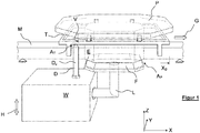
- FIG. 1 shows the essential components of a conveyor device according to the invention in a simplified perspective view.
- a carrier T is movable in a conveyor direction G along a stationary conveyor element M designed as a rail.
- the carrier T carries a product holder P, on which products not shown in detail (individually or in groups) can rest in order to move them along a production line.
- the product holder P can be lifted out of the carrier T upwards in the Z direction.
- Driven conveyor links for example drivers, chain links or hooks which can move the carrier T along the conveyor element M are not shown in detail.
- a load cell W shown schematically, is arranged below the conveyor element M.
- the load cell W comprises an angled load introduction section L, which in turn carries a centering unit F which is positioned essentially below the foot E of the product holder P.
- the weight of the product holder P can be introduced into a weighing mechanism (not shown in detail) in the weighing cell W via the load introduction section in order to generate an evaluable weighing signal therefrom.
- All weighing mechanisms known to the person skilled in the art also independent of the present exemplary figures, can be used to generate the weighing signal, the method of electromagnetic force compensation being mentioned in particular.
- the weighing cell W can be moved up and down in a lifting direction H and thus relative to the conveying element M via a lifting mechanism (not shown in detail).
- the stroke direction H coincides with the vertical Z-axis.
- the carrier T in Figure 1 reaches a machining position X B and rests there initially.
- the carrier T must be transferred to a target carrier position which can be precisely predefined in particular by means of its X and Y coordinates. This is necessary in order to be able to ensure that the product holder P is released from the carrier T.
- the device has first alignment means A T which are formed partly on the carrier T and partly on the weighing cell W.
- the carrier T comprises an alignment opening V in the form of a bore, the axis of which runs in the Z direction.
- a cylindrical mandrel D is formed around an axis D Z , which also extends in the Z direction.
- the outside diameter of the mandrel D is slightly smaller than the inside diameter of the alignment opening V.
- the mandrel D is provided with a conical section which facilitates threading into the alignment opening V and at the same time the alignment of the carrier T relative to the mandrel in the XY plane causes.
- the centering unit F has a pyramid section with conically tapering outer surfaces at its upper end. These are part of the second alignment means A P with which the product holder P is released from the carrier T.
- the foot E of the product holder P is open at the bottom and is designed with inner surfaces, not shown in detail, which also belong to the second alignment means A P.
- the spatial arrangement of the load cell W with the mandrel D and the centering unit F is selected so that in an essentially straight, preferably continuous upward movement of the load cell W, the carrier T is first aligned over the mandrel D and then the product holder P is removed from the Carrier T is lifted out so that the product holder P rests on the load introduction section L without force shunting and thus introduces its full weight into the load cell W.
- the arrangement of the mandrel D and the centering unit F to one another thus also determines the position of the carrier T relative to the product holder P at the moment of release.
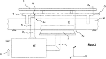
- the alignment or release is illustrated with schematic side views.
- Figure 2 shows how the load cell W is raised in the direction H relative to the conveyor element M with the carrier T resting on it and the product holder P resting thereon.
- the mandrel D is about to engage the alignment opening V of the carrier T.
- the centering unit F is not yet in contact with the foot E of the product holder P.
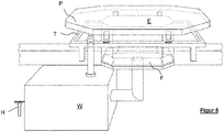
- Figure 4 shows that the balance W has been raised completely in the height direction H.
- the mandrel D has been pushed further through the alignment opening V without further changing the XY position of the carrier.
- the centering unit F has meanwhile completely gripped the foot E of the product holder P and lifted the product holder P out of the carrier T.
- the product holder P thus rests exclusively on the load introduction section L of the weighing cell W, so that the weight of the product holder (with or without the product lying on it) can be recorded by the weighing cell.
- the carrier T is secured in the horizontal direction by the mandrel D during the weighing process, so that during the subsequent downward movement of the weighing cell W (not shown in detail) the product holder P can be reinserted into the carrier T in order to transport it further.
- Figure 5 shows the state according to Figure 4 in a simplified perspective view.
Landscapes
- Engineering & Computer Science (AREA)
- Mechanical Engineering (AREA)
- Physics & Mathematics (AREA)
- General Physics & Mathematics (AREA)
- Specific Conveyance Elements (AREA)
- Sorting Of Articles (AREA)
- Attitude Control For Articles On Conveyors (AREA)
Applications Claiming Priority (1)
| Application Number | Priority Date | Filing Date | Title |
|---|---|---|---|
| DE202019102508.5U DE202019102508U1 (de) | 2019-05-03 | 2019-05-03 | Fördereinrichtung |
Publications (2)
| Publication Number | Publication Date |
|---|---|
| EP3733342A1 true EP3733342A1 (fr) | 2020-11-04 |
| EP3733342B1 EP3733342B1 (fr) | 2023-07-26 |
Family
ID=66675110
Family Applications (1)
| Application Number | Title | Priority Date | Filing Date |
|---|---|---|---|
| EP20171889.7A Active EP3733342B1 (fr) | 2019-05-03 | 2020-04-28 | Dispositif de transport |
Country Status (3)
| Country | Link |
|---|---|
| US (1) | US11447347B2 (fr) |
| EP (1) | EP3733342B1 (fr) |
| DE (1) | DE202019102508U1 (fr) |
Citations (3)
| Publication number | Priority date | Publication date | Assignee | Title |
|---|---|---|---|---|
| DE202005017255U1 (de) * | 2005-01-08 | 2006-01-12 | Sartorius Ag | Vorrichtung zum Beschicken einer Waage mit flachem Wägegut |
| CH695561A5 (de) * | 2001-09-18 | 2006-06-30 | Bosch Gmbh Robert | Vorrichtung zum Positionieren eines Werkstückträgers. |
| DE102016207600A1 (de) * | 2016-05-03 | 2017-11-09 | Robert Bosch Gmbh | Vorrichtung und Verfahren zum Wiegen sowie Vorrichtung und Verfahren zum Befüllen |
Family Cites Families (14)
| Publication number | Priority date | Publication date | Assignee | Title |
|---|---|---|---|---|
| US2903120A (en) * | 1956-04-13 | 1959-09-08 | Edward J Skinner Ltd | Planetary transfer machines |
| US3858707A (en) * | 1973-11-07 | 1975-01-07 | Rockford Automation | Conveyor system |
| US3990212A (en) * | 1975-07-17 | 1976-11-09 | Flodin, Inc. | Carton filling and weighing device |
| US4201284A (en) * | 1978-11-02 | 1980-05-06 | Brems John Henry | Pallet registry system |
| US4570782A (en) * | 1980-10-20 | 1986-02-18 | Cargill Detroit Corporation | Non-synchronous rotary manufacturing system |
| US4611676A (en) * | 1985-07-01 | 1986-09-16 | Tobacco Research And Development Institute Limited | Weighbelt apparatus |
| US6414251B1 (en) | 1999-04-19 | 2002-07-02 | Breck Colquett | Weighing apparatus and method having automatic tolerance analysis and calibration |
| ATE550138T1 (de) * | 2007-09-14 | 2012-04-15 | Flexlink Components Ab | Hubvorrichtung für ein fördersystem, fördersystem und verfahren |
| DE102009013545B4 (de) * | 2009-03-19 | 2013-02-21 | Wipotec Wiege- Und Positioniersysteme Gmbh | Dichtmechanismus |
| DE102013212317A1 (de) | 2013-06-26 | 2014-12-31 | Siemens Aktiengesellschaft | Fördervorrichtung zum Transport und zur Lageausrichtung eines Stückgutes sowie Sortierförderanlage mit einer solchen Fördervorrichtung |
| DE102014106400A1 (de) * | 2014-04-25 | 2015-11-12 | Weber Maschinenbau Gmbh Breidenbach | Individueller transport von lebensmittelportionen |
| NL2014325B1 (en) | 2015-02-20 | 2016-10-13 | Optimus Sorter Holding B V | A conveyor system comprising a plurality of support members and a method thereof. |
| DE102015104023A1 (de) * | 2015-03-18 | 2016-09-22 | Weber Maschinenbau Gmbh Breidenbach | Vorrichtung zum Bewegen von Objekten |
| LU93196B1 (de) | 2016-09-02 | 2018-04-05 | Hoernle Stephan | Werkstückträger |
-
2019
- 2019-05-03 DE DE202019102508.5U patent/DE202019102508U1/de active Active
-
2020
- 2020-04-27 US US16/859,911 patent/US11447347B2/en active Active
- 2020-04-28 EP EP20171889.7A patent/EP3733342B1/fr active Active
Patent Citations (3)
| Publication number | Priority date | Publication date | Assignee | Title |
|---|---|---|---|---|
| CH695561A5 (de) * | 2001-09-18 | 2006-06-30 | Bosch Gmbh Robert | Vorrichtung zum Positionieren eines Werkstückträgers. |
| DE202005017255U1 (de) * | 2005-01-08 | 2006-01-12 | Sartorius Ag | Vorrichtung zum Beschicken einer Waage mit flachem Wägegut |
| DE102016207600A1 (de) * | 2016-05-03 | 2017-11-09 | Robert Bosch Gmbh | Vorrichtung und Verfahren zum Wiegen sowie Vorrichtung und Verfahren zum Befüllen |
Also Published As
| Publication number | Publication date |
|---|---|
| EP3733342B1 (fr) | 2023-07-26 |
| DE202019102508U1 (de) | 2019-05-14 |
| US11447347B2 (en) | 2022-09-20 |
| US20200361712A1 (en) | 2020-11-19 |
Similar Documents
| Publication | Publication Date | Title |
|---|---|---|
| EP3342719B1 (fr) | Dispositif et procédé destinés au remplissage de récipients emboîtés | |
| AT519452B1 (de) | Verfahren und Vorrichtung zum Kommissionieren von Waren | |
| DE69611128T2 (de) | Verfahren und Vorrichtung zum Sortieren von Poststücken unter Verwendung von Pufferbehältern bei den Sortierausgängen | |
| AT391671B (de) | Verfahren und vorrichtung zum automatischen stapeln, lagern und entnehmen von stueckgut | |
| EP0569689B1 (fr) | Procédé et dispositif de tri de bouteilles | |
| DE202021105697U1 (de) | Maschine zum Sortieren und Stapeln von Behältern mit Klappwänden | |
| DE69800375T2 (de) | Oberirdisches System zum Transportieren, Lagern, Klassifizieren und Kontrollieren von leichten Fabrikaten | |
| EP2499501B1 (fr) | Dispositif d'extraction de contenants et machine d'emballage | |
| EP1243349A1 (fr) | Méthode et dispositif pour remplir et pour évacuer automatiquement des récipients de produits triés | |
| EP3814239B1 (fr) | Installation de traitement de contenants et procédé de régulation | |
| DE102013205628A1 (de) | Palettiersystem | |
| DE102024121648A1 (de) | Vorrichtung und Verfahren zum Verarbeiten pharmazeutischer Behälter | |
| WO2018162762A1 (fr) | Système de détection et de tri de marchandises | |
| DE69713674T2 (de) | Vorrichtung zum dynamischen Wägen von Früchten | |
| EP3733342B1 (fr) | Dispositif de transport | |
| DE102013108820A1 (de) | Verfahren und Vorrichtung zur Bestückung mit Behältnissen eines Typs in einem Gebinde | |
| DE102004012043A1 (de) | Vorrichtung und Verfahren zum lagegerechten Übergeben von quaderförmigen Waren | |
| DE69512394T2 (de) | Vorrichtung und verfahren zum fördern von individuellen gegenstaenden | |
| DE19652756C1 (de) | Vorrichtung zum Zusammenfügen von Möbelkorpussen | |
| EP2746172B1 (fr) | Procédé et dispositif de pesage de gerbes sur un dispositif de transport | |
| WO2015090546A1 (fr) | Procédé et dispositif de traitement de documents de valeur | |
| DE602005005686T2 (de) | Vorrichtung zum Sortieren und Gruppieren von Gegenständen, Behältern u.ä. | |
| EP4442375A1 (fr) | Dispositif et procédé de tri d'objets | |
| DE102023000184A1 (de) | Generieren von Daten beim Übergeben von autonom fahrenden Hängetaschen in ein Hängetaschenlager | |
| AT406551B (de) | Anlage zum sortieren von werkstücken |
Legal Events
| Date | Code | Title | Description |
|---|---|---|---|
| PUAI | Public reference made under article 153(3) epc to a published international application that has entered the european phase |
Free format text: ORIGINAL CODE: 0009012 |
|
| STAA | Information on the status of an ep patent application or granted ep patent |
Free format text: STATUS: THE APPLICATION HAS BEEN PUBLISHED |
|
| AK | Designated contracting states |
Kind code of ref document: A1 Designated state(s): AL AT BE BG CH CY CZ DE DK EE ES FI FR GB GR HR HU IE IS IT LI LT LU LV MC MK MT NL NO PL PT RO RS SE SI SK SM TR |
|
| AX | Request for extension of the european patent |
Extension state: BA ME |
|
| STAA | Information on the status of an ep patent application or granted ep patent |
Free format text: STATUS: REQUEST FOR EXAMINATION WAS MADE |
|
| 17P | Request for examination filed |
Effective date: 20210503 |
|
| RBV | Designated contracting states (corrected) |
Designated state(s): AL AT BE BG CH CY CZ DE DK EE ES FI FR GB GR HR HU IE IS IT LI LT LU LV MC MK MT NL NO PL PT RO RS SE SI SK SM TR |
|
| GRAP | Despatch of communication of intention to grant a patent |
Free format text: ORIGINAL CODE: EPIDOSNIGR1 |
|
| STAA | Information on the status of an ep patent application or granted ep patent |
Free format text: STATUS: GRANT OF PATENT IS INTENDED |
|
| INTG | Intention to grant announced |
Effective date: 20230214 |
|
| GRAS | Grant fee paid |
Free format text: ORIGINAL CODE: EPIDOSNIGR3 |
|
| GRAA | (expected) grant |
Free format text: ORIGINAL CODE: 0009210 |
|
| STAA | Information on the status of an ep patent application or granted ep patent |
Free format text: STATUS: THE PATENT HAS BEEN GRANTED |
|
| AK | Designated contracting states |
Kind code of ref document: B1 Designated state(s): AL AT BE BG CH CY CZ DE DK EE ES FI FR GB GR HR HU IE IS IT LI LT LU LV MC MK MT NL NO PL PT RO RS SE SI SK SM TR |
|
| REG | Reference to a national code |
Ref country code: CH Ref legal event code: EP |
|
| REG | Reference to a national code |
Ref country code: IE Ref legal event code: FG4D Free format text: LANGUAGE OF EP DOCUMENT: GERMAN |
|
| REG | Reference to a national code |
Ref country code: DE Ref legal event code: R096 Ref document number: 502020004332 Country of ref document: DE |
|
| REG | Reference to a national code |
Ref country code: LT Ref legal event code: MG9D |
|
| REG | Reference to a national code |
Ref country code: NL Ref legal event code: MP Effective date: 20230726 |
|
| PG25 | Lapsed in a contracting state [announced via postgrant information from national office to epo] |
Ref country code: NL Free format text: LAPSE BECAUSE OF FAILURE TO SUBMIT A TRANSLATION OF THE DESCRIPTION OR TO PAY THE FEE WITHIN THE PRESCRIBED TIME-LIMIT Effective date: 20230726 |
|
| PG25 | Lapsed in a contracting state [announced via postgrant information from national office to epo] |
Ref country code: GR Free format text: LAPSE BECAUSE OF FAILURE TO SUBMIT A TRANSLATION OF THE DESCRIPTION OR TO PAY THE FEE WITHIN THE PRESCRIBED TIME-LIMIT Effective date: 20231027 |
|
| PG25 | Lapsed in a contracting state [announced via postgrant information from national office to epo] |
Ref country code: IS Free format text: LAPSE BECAUSE OF FAILURE TO SUBMIT A TRANSLATION OF THE DESCRIPTION OR TO PAY THE FEE WITHIN THE PRESCRIBED TIME-LIMIT Effective date: 20231126 |
|
| PG25 | Lapsed in a contracting state [announced via postgrant information from national office to epo] |
Ref country code: SE Free format text: LAPSE BECAUSE OF FAILURE TO SUBMIT A TRANSLATION OF THE DESCRIPTION OR TO PAY THE FEE WITHIN THE PRESCRIBED TIME-LIMIT Effective date: 20230726 Ref country code: RS Free format text: LAPSE BECAUSE OF FAILURE TO SUBMIT A TRANSLATION OF THE DESCRIPTION OR TO PAY THE FEE WITHIN THE PRESCRIBED TIME-LIMIT Effective date: 20230726 Ref country code: PT Free format text: LAPSE BECAUSE OF FAILURE TO SUBMIT A TRANSLATION OF THE DESCRIPTION OR TO PAY THE FEE WITHIN THE PRESCRIBED TIME-LIMIT Effective date: 20231127 Ref country code: NO Free format text: LAPSE BECAUSE OF FAILURE TO SUBMIT A TRANSLATION OF THE DESCRIPTION OR TO PAY THE FEE WITHIN THE PRESCRIBED TIME-LIMIT Effective date: 20231026 Ref country code: LV Free format text: LAPSE BECAUSE OF FAILURE TO SUBMIT A TRANSLATION OF THE DESCRIPTION OR TO PAY THE FEE WITHIN THE PRESCRIBED TIME-LIMIT Effective date: 20230726 Ref country code: LT Free format text: LAPSE BECAUSE OF FAILURE TO SUBMIT A TRANSLATION OF THE DESCRIPTION OR TO PAY THE FEE WITHIN THE PRESCRIBED TIME-LIMIT Effective date: 20230726 Ref country code: IS Free format text: LAPSE BECAUSE OF FAILURE TO SUBMIT A TRANSLATION OF THE DESCRIPTION OR TO PAY THE FEE WITHIN THE PRESCRIBED TIME-LIMIT Effective date: 20231126 Ref country code: HR Free format text: LAPSE BECAUSE OF FAILURE TO SUBMIT A TRANSLATION OF THE DESCRIPTION OR TO PAY THE FEE WITHIN THE PRESCRIBED TIME-LIMIT Effective date: 20230726 Ref country code: GR Free format text: LAPSE BECAUSE OF FAILURE TO SUBMIT A TRANSLATION OF THE DESCRIPTION OR TO PAY THE FEE WITHIN THE PRESCRIBED TIME-LIMIT Effective date: 20231027 Ref country code: FI Free format text: LAPSE BECAUSE OF FAILURE TO SUBMIT A TRANSLATION OF THE DESCRIPTION OR TO PAY THE FEE WITHIN THE PRESCRIBED TIME-LIMIT Effective date: 20230726 |
|
| PG25 | Lapsed in a contracting state [announced via postgrant information from national office to epo] |
Ref country code: PL Free format text: LAPSE BECAUSE OF FAILURE TO SUBMIT A TRANSLATION OF THE DESCRIPTION OR TO PAY THE FEE WITHIN THE PRESCRIBED TIME-LIMIT Effective date: 20230726 |
|
| PG25 | Lapsed in a contracting state [announced via postgrant information from national office to epo] |
Ref country code: ES Free format text: LAPSE BECAUSE OF FAILURE TO SUBMIT A TRANSLATION OF THE DESCRIPTION OR TO PAY THE FEE WITHIN THE PRESCRIBED TIME-LIMIT Effective date: 20230726 |
|
| REG | Reference to a national code |
Ref country code: DE Ref legal event code: R097 Ref document number: 502020004332 Country of ref document: DE |
|
| PG25 | Lapsed in a contracting state [announced via postgrant information from national office to epo] |
Ref country code: SM Free format text: LAPSE BECAUSE OF FAILURE TO SUBMIT A TRANSLATION OF THE DESCRIPTION OR TO PAY THE FEE WITHIN THE PRESCRIBED TIME-LIMIT Effective date: 20230726 Ref country code: RO Free format text: LAPSE BECAUSE OF FAILURE TO SUBMIT A TRANSLATION OF THE DESCRIPTION OR TO PAY THE FEE WITHIN THE PRESCRIBED TIME-LIMIT Effective date: 20230726 Ref country code: ES Free format text: LAPSE BECAUSE OF FAILURE TO SUBMIT A TRANSLATION OF THE DESCRIPTION OR TO PAY THE FEE WITHIN THE PRESCRIBED TIME-LIMIT Effective date: 20230726 Ref country code: EE Free format text: LAPSE BECAUSE OF FAILURE TO SUBMIT A TRANSLATION OF THE DESCRIPTION OR TO PAY THE FEE WITHIN THE PRESCRIBED TIME-LIMIT Effective date: 20230726 Ref country code: DK Free format text: LAPSE BECAUSE OF FAILURE TO SUBMIT A TRANSLATION OF THE DESCRIPTION OR TO PAY THE FEE WITHIN THE PRESCRIBED TIME-LIMIT Effective date: 20230726 Ref country code: CZ Free format text: LAPSE BECAUSE OF FAILURE TO SUBMIT A TRANSLATION OF THE DESCRIPTION OR TO PAY THE FEE WITHIN THE PRESCRIBED TIME-LIMIT Effective date: 20230726 Ref country code: SK Free format text: LAPSE BECAUSE OF FAILURE TO SUBMIT A TRANSLATION OF THE DESCRIPTION OR TO PAY THE FEE WITHIN THE PRESCRIBED TIME-LIMIT Effective date: 20230726 |
|
| PG25 | Lapsed in a contracting state [announced via postgrant information from national office to epo] |
Ref country code: IT Free format text: LAPSE BECAUSE OF FAILURE TO SUBMIT A TRANSLATION OF THE DESCRIPTION OR TO PAY THE FEE WITHIN THE PRESCRIBED TIME-LIMIT Effective date: 20230726 |
|
| PLBE | No opposition filed within time limit |
Free format text: ORIGINAL CODE: 0009261 |
|
| STAA | Information on the status of an ep patent application or granted ep patent |
Free format text: STATUS: NO OPPOSITION FILED WITHIN TIME LIMIT |
|
| 26N | No opposition filed |
Effective date: 20240429 |
|
| PG25 | Lapsed in a contracting state [announced via postgrant information from national office to epo] |
Ref country code: SI Free format text: LAPSE BECAUSE OF FAILURE TO SUBMIT A TRANSLATION OF THE DESCRIPTION OR TO PAY THE FEE WITHIN THE PRESCRIBED TIME-LIMIT Effective date: 20230726 |
|
| PG25 | Lapsed in a contracting state [announced via postgrant information from national office to epo] |
Ref country code: BG Free format text: LAPSE BECAUSE OF FAILURE TO SUBMIT A TRANSLATION OF THE DESCRIPTION OR TO PAY THE FEE WITHIN THE PRESCRIBED TIME-LIMIT Effective date: 20230726 |
|
| PG25 | Lapsed in a contracting state [announced via postgrant information from national office to epo] |
Ref country code: MC Free format text: LAPSE BECAUSE OF FAILURE TO SUBMIT A TRANSLATION OF THE DESCRIPTION OR TO PAY THE FEE WITHIN THE PRESCRIBED TIME-LIMIT Effective date: 20230726 |
|
| PG25 | Lapsed in a contracting state [announced via postgrant information from national office to epo] |
Ref country code: MC Free format text: LAPSE BECAUSE OF FAILURE TO SUBMIT A TRANSLATION OF THE DESCRIPTION OR TO PAY THE FEE WITHIN THE PRESCRIBED TIME-LIMIT Effective date: 20230726 Ref country code: BG Free format text: LAPSE BECAUSE OF FAILURE TO SUBMIT A TRANSLATION OF THE DESCRIPTION OR TO PAY THE FEE WITHIN THE PRESCRIBED TIME-LIMIT Effective date: 20230726 |
|
| REG | Reference to a national code |
Ref country code: CH Ref legal event code: PL |
|
| PG25 | Lapsed in a contracting state [announced via postgrant information from national office to epo] |
Ref country code: LU Free format text: LAPSE BECAUSE OF NON-PAYMENT OF DUE FEES Effective date: 20240428 |
|
| GBPC | Gb: european patent ceased through non-payment of renewal fee |
Effective date: 20240428 |
|
| REG | Reference to a national code |
Ref country code: BE Ref legal event code: MM Effective date: 20240430 |
|
| PG25 | Lapsed in a contracting state [announced via postgrant information from national office to epo] |
Ref country code: LU Free format text: LAPSE BECAUSE OF NON-PAYMENT OF DUE FEES Effective date: 20240428 |
|
| PG25 | Lapsed in a contracting state [announced via postgrant information from national office to epo] |
Ref country code: BE Free format text: LAPSE BECAUSE OF NON-PAYMENT OF DUE FEES Effective date: 20240430 |
|
| PG25 | Lapsed in a contracting state [announced via postgrant information from national office to epo] |
Ref country code: GB Free format text: LAPSE BECAUSE OF NON-PAYMENT OF DUE FEES Effective date: 20240428 |
|
| PG25 | Lapsed in a contracting state [announced via postgrant information from national office to epo] |
Ref country code: FR Free format text: LAPSE BECAUSE OF NON-PAYMENT OF DUE FEES Effective date: 20240430 |
|
| PG25 | Lapsed in a contracting state [announced via postgrant information from national office to epo] |
Ref country code: GB Free format text: LAPSE BECAUSE OF NON-PAYMENT OF DUE FEES Effective date: 20240428 Ref country code: FR Free format text: LAPSE BECAUSE OF NON-PAYMENT OF DUE FEES Effective date: 20240430 Ref country code: BE Free format text: LAPSE BECAUSE OF NON-PAYMENT OF DUE FEES Effective date: 20240430 Ref country code: CH Free format text: LAPSE BECAUSE OF NON-PAYMENT OF DUE FEES Effective date: 20240430 |
|
| PG25 | Lapsed in a contracting state [announced via postgrant information from national office to epo] |
Ref country code: IE Free format text: LAPSE BECAUSE OF NON-PAYMENT OF DUE FEES Effective date: 20240428 |
|
| PGFP | Annual fee paid to national office [announced via postgrant information from national office to epo] |
Ref country code: DE Payment date: 20250331 Year of fee payment: 6 |
|
| PGFP | Annual fee paid to national office [announced via postgrant information from national office to epo] |
Ref country code: AT Payment date: 20250721 Year of fee payment: 5 |
|
| PG25 | Lapsed in a contracting state [announced via postgrant information from national office to epo] |
Ref country code: CY Free format text: LAPSE BECAUSE OF FAILURE TO SUBMIT A TRANSLATION OF THE DESCRIPTION OR TO PAY THE FEE WITHIN THE PRESCRIBED TIME-LIMIT; INVALID AB INITIO Effective date: 20200428 |
|
| PG25 | Lapsed in a contracting state [announced via postgrant information from national office to epo] |
Ref country code: HU Free format text: LAPSE BECAUSE OF FAILURE TO SUBMIT A TRANSLATION OF THE DESCRIPTION OR TO PAY THE FEE WITHIN THE PRESCRIBED TIME-LIMIT; INVALID AB INITIO Effective date: 20200428 |