EP3733361B1 - Verfahren zur bestimmung einer fehlfunktion und vorrichtung zur bestimmung einer fehlfunktion - Google Patents
Verfahren zur bestimmung einer fehlfunktion und vorrichtung zur bestimmung einer fehlfunktion Download PDFInfo
- Publication number
- EP3733361B1 EP3733361B1 EP17936814.7A EP17936814A EP3733361B1 EP 3733361 B1 EP3733361 B1 EP 3733361B1 EP 17936814 A EP17936814 A EP 17936814A EP 3733361 B1 EP3733361 B1 EP 3733361B1
- Authority
- EP
- European Patent Office
- Prior art keywords
- malfunction determination
- malfunction
- period
- production machine
- operation stop
- Prior art date
- Legal status (The legal status is an assumption and is not a legal conclusion. Google has not performed a legal analysis and makes no representation as to the accuracy of the status listed.)
- Active
Links
Images




Classifications
-
- B—PERFORMING OPERATIONS; TRANSPORTING
- B25—HAND TOOLS; PORTABLE POWER-DRIVEN TOOLS; MANIPULATORS
- B25J—MANIPULATORS; CHAMBERS PROVIDED WITH MANIPULATION DEVICES
- B25J9/00—Program-controlled manipulators
- B25J9/16—Program controls
- B25J9/1674—Program controls characterised by safety, monitoring, diagnostic
-
- B—PERFORMING OPERATIONS; TRANSPORTING
- B25—HAND TOOLS; PORTABLE POWER-DRIVEN TOOLS; MANIPULATORS
- B25J—MANIPULATORS; CHAMBERS PROVIDED WITH MANIPULATION DEVICES
- B25J13/00—Controls for manipulators
- B25J13/08—Controls for manipulators by means of sensing devices, e.g. viewing or touching devices
- B25J13/085—Force or torque sensors
-
- B—PERFORMING OPERATIONS; TRANSPORTING
- B25—HAND TOOLS; PORTABLE POWER-DRIVEN TOOLS; MANIPULATORS
- B25J—MANIPULATORS; CHAMBERS PROVIDED WITH MANIPULATION DEVICES
- B25J13/00—Controls for manipulators
- B25J13/08—Controls for manipulators by means of sensing devices, e.g. viewing or touching devices
- B25J13/087—Controls for manipulators by means of sensing devices, e.g. viewing or touching devices for sensing other physical parameters, e.g. electrical or chemical properties
-
- B—PERFORMING OPERATIONS; TRANSPORTING
- B25—HAND TOOLS; PORTABLE POWER-DRIVEN TOOLS; MANIPULATORS
- B25J—MANIPULATORS; CHAMBERS PROVIDED WITH MANIPULATION DEVICES
- B25J19/00—Accessories fitted to manipulators, e.g. for monitoring, for viewing; Safety devices combined with or specially adapted for use in connection with manipulators
- B25J19/06—Safety devices
-
- B—PERFORMING OPERATIONS; TRANSPORTING
- B25—HAND TOOLS; PORTABLE POWER-DRIVEN TOOLS; MANIPULATORS
- B25J—MANIPULATORS; CHAMBERS PROVIDED WITH MANIPULATION DEVICES
- B25J9/00—Program-controlled manipulators
- B25J9/10—Program-controlled manipulators characterised by positioning means for manipulator elements
- B25J9/12—Program-controlled manipulators characterised by positioning means for manipulator elements electric
-
- G—PHYSICS
- G05—CONTROLLING; REGULATING
- G05B—CONTROL OR REGULATING SYSTEMS IN GENERAL; FUNCTIONAL ELEMENTS OF SUCH SYSTEMS; MONITORING OR TESTING ARRANGEMENTS FOR SUCH SYSTEMS OR ELEMENTS
- G05B19/00—Program-control systems
- G05B19/02—Program-control systems electric
- G05B19/18—Numerical control [NC], i.e. automatically operating machines, in particular machine tools, e.g. in a manufacturing environment, so as to execute positioning, movement or co-ordinated operations by means of program data in numerical form
- G05B19/406—Numerical control [NC], i.e. automatically operating machines, in particular machine tools, e.g. in a manufacturing environment, so as to execute positioning, movement or co-ordinated operations by means of program data in numerical form characterised by monitoring or safety
- G05B19/4062—Monitoring servoloop, e.g. overload of servomotor, loss of feedback or reference
-
- G—PHYSICS
- G05—CONTROLLING; REGULATING
- G05B—CONTROL OR REGULATING SYSTEMS IN GENERAL; FUNCTIONAL ELEMENTS OF SUCH SYSTEMS; MONITORING OR TESTING ARRANGEMENTS FOR SUCH SYSTEMS OR ELEMENTS
- G05B23/00—Testing or monitoring of control systems or parts thereof
- G05B23/02—Electric testing or monitoring
- G05B23/0205—Electric testing or monitoring by means of a monitoring system capable of detecting and responding to faults
- G05B23/0218—Electric testing or monitoring by means of a monitoring system capable of detecting and responding to faults characterised by the fault detection method dealing with either existing or incipient faults
- G05B23/0243—Electric testing or monitoring by means of a monitoring system capable of detecting and responding to faults characterised by the fault detection method dealing with either existing or incipient faults model based detection method, e.g. first-principles knowledge model
- G05B23/0245—Electric testing or monitoring by means of a monitoring system capable of detecting and responding to faults characterised by the fault detection method dealing with either existing or incipient faults model based detection method, e.g. first-principles knowledge model based on a qualitative model, e.g. rule based; if-then decisions
-
- G—PHYSICS
- G05—CONTROLLING; REGULATING
- G05B—CONTROL OR REGULATING SYSTEMS IN GENERAL; FUNCTIONAL ELEMENTS OF SUCH SYSTEMS; MONITORING OR TESTING ARRANGEMENTS FOR SUCH SYSTEMS OR ELEMENTS
- G05B2219/00—Program-control systems
- G05B2219/30—Nc systems
- G05B2219/37—Measurements
- G05B2219/37435—Vibration of machine
Definitions
- the present invention relates to a malfunction determination method and a malfunction determination device for acquiring sensor data of a sensor that detects a condition of a production machine including a motor as a driving source of a rotating mechanism, so as to determine a malfunction of the production machine.
- An abnormal load detection device that detects an abnormal load applied to a motor, as disclosed in Patent Document 1.
- the abnormal load detection device disclosed in Patent Document 1 determines that the current operation is in a normal state without detecting an abnormal load when a rotation speed of the motor falls below a reference speed, such as when the motor stops, starts rotating, or rotates at a low speed, since such a situation tends to lead to false detection of an abnormality.
- Other abnormal load detection devices are disclosed in Patent Document 2 and Patent Document 3.
- Patent Document 1 Japanese Unexamined Patent Application Publication No. 2007-219991
- Patent Document 2 JP 2002 175104 A
- Patent Document 3 US 2007/244609 A1 .
- Patent Document 1 still has a problem of false detection in a production machine such as a production robot, which is sometimes determined to have a malfunction regardless of the operational condition of the motor, such as a rotation speed.
- a production machine such as a production robot
- the production machine which has stopped its operation for a long period of time but then starts the operation, may be wrongly determined to have a malfunction immediately after the start even though there is no malfunction in the production machine.
- the method disclosed in Patent Document 1 thus cannot avoid false detection of a malfunction in the production machine which has not been operated for a long period of time, since the operating state of the production machine has no relationship with the operational condition of the motor.
- the present invention provides a malfunction determination method and a malfunction determination device capable of preventing false detection of a malfunction of a production machine under circumstances having no relationship with an operational condition of a motor, such as when the production machine has stopped its operation for a long period of time.
- a malfunction determination method and device according to the invention are defined in the appended independent claims. Specific embodiments are defined in the dependent claims.
- the present invention can provide the malfunction determination method and device capable of preventing false detection of a malfunction of the production machine made under the circumstances having no relationship with an operational condition of a motor, such as when the production machine has stopped its operation for a long period of time.
- Fig. 1 is a block diagram illustrating a configuration of a malfunction determination system including a malfunction determination device according to the present embodiment.
- the malfunction determination system 100 includes a production robot 1, a malfunction determination device 3, and a user interface 5.
- the production robot 1 is a production machine including a plurality of motor drive systems as joint shafts.
- the motor drive systems include a motor as a driving source of a rotating mechanism of a robot arm, for example.
- the motor drives the robot arm via a reducer.
- the production robot 1 includes a sensor 11, a calculation unit 13, and a communication unit 15.
- the sensor 11 detects a condition of the production robot 1 including various kinds of data on the motor drive systems necessary for determining a malfunction of the production robot 1. For example, the sensor 11 detects a rotational angle position, speed, and torque value of the motor, and a vibration value of the rotating mechanism such as the reducer.
- the calculation unit 13 obtains a difference between the torque value detected by the sensor 11 and a motor control value so as to calculate a disturbance torque value.
- the communication unit 15 has a function of communicating necessary data with the malfunction determination device 3 through a local area network (LAN), for example. In particular, the communication unit 15 transmits sensor data indicating the condition of the production robot 1.
- the sensor data includes the rotational angle position, speed, and torque value of the motor, the vibration value of the rotating mechanism, and the disturbance torque value.
- the malfunction determination device 3 acquires the sensor data of the sensor 11 for detecting the condition of the production robot 1 so as to determine a malfunction of the production robot 1.
- the malfunction determination device 3 includes a communication unit 21, an operation status determination unit 23, a suspension period setting unit 25, a malfunction determination unit 27, a sensor information database 29, a maintenance history database 31, and an operation history database 33.
- the malfunction determination device 3 is implemented by a general-purpose electronic circuit including a microcomputer, a microprocessor, and a CPU, and a peripheral device including memory.
- the malfunction determination device 3 serves as the communication unit 21, the operation status determination unit 23, the suspension period setting unit 25, and the malfunction determination unit 27 when a predetermined program is executed.
- the respective functions of the malfunction determination device 3 can be implemented in single or plural processing circuits.
- the respective processing circuits include a programmed processing device, such as a processing device including an electric circuit, including an application-specific integrated circuit (ASIC) configured to execute the functions described in the embodiment or conventional circuit components.
- ASIC application-specific integrated circuit
- the communication unit 21 has a function of communicating necessary data with the communication unit 15 of the production robot 1 through the LAN, for example.
- the communication unit 21 receives the sensor data indicating the condition of the production robot 1.
- the operation status determination unit 23 determines whether the production robot 1 has an operation stop period during which the production robot 1 has stopped its operation for a predetermined period of time or longer, in accordance with the operation history of the production robot 1. In particular, the operation status determination unit 23 acquires an operation start time and date and an operation stop time and date of the production robot 1 from the operation history database 33 to calculate the operation stop period. The operation status determination unit 23 then compares the calculated operation stop period with a predetermined threshold so as to determine whether the production robot 1 has the operation stop period during which the production robot 1 has stopped the operation for a predetermined period or longer. For example, the operation status determination unit 23 determines whether there are operation stop periods of six hours or longer, two days or longer, ten days or longer, and twenty days or longer.
- the suspension period setting unit 25 sets a malfunction determination suspension period during which the determination of a malfunction of the production robot 1 is suspended, in accordance with the length of the operation stop period when the production robot 1 is determined to have the operation stop period.
- the malfunction determination suspension period is set from a point at which the production robot 1 starts operating after the operation stop period ends. The determination of a malfunction of the production robot 1 by the malfunction determination unit 27 is suspended during the malfunction determination suspension period.
- the suspension period setting unit 25 sets the malfunction determination suspension period immediately after the operation stop period in accordance with the length of the operation stop period, so as to prevent false detection of a malfunction. Since the viscosity of lubricating oil is increased as the operation stop period is longer, the suspension period setting unit 25 sets the malfunction determination suspension period to be longer as the operation stop period is longer.
- the malfunction determination unit 27 determines whether the production robot 1 has a malfunction by use of the sensor data indicating the condition of the production robot 1. In particular, the malfunction determination unit 27 acquires the sensor data during a predetermined period from the sensor information database 29 to determine whether the production robot 1 has a malfunction.
- the determination of a malfunction includes a process of calculating a malfunction determination value such as a difference rate of the disturbance torque to determine a malfunction of the production robot 1 depending on whether the malfunction determination value is a predetermined threshold or greater.
- the malfunction determination unit 27 determines whether the production robot 1 has a malfunction in a period other than the malfunction determination suspension period. Namely, the malfunction determination unit 27 determines whether the production robot 1 has a malfunction by use of the sensor data for a period other than the malfunction determination suspension period.
- the sensor information database 29 accumulates the sensor data indicating the condition of the production robot 1. For example, the sensor information database 29 acquires and accumulates, through the respective communication units 15 and 21, data including the rotational angle position, speed, and torque value of the motor, and the vibration value of the rotating mechanism detected by the sensor 11, and data including the disturbance torque value calculated by the calculation unit 13.
- the maintenance history database 31 accumulates maintenance history data of the production robot 1. For example, the maintenance history database 31 accumulates maintenance records including a date on which the reducer was replaced, and a time and date at which grease was reapplied.
- the operation history database 33 accumulates operation history data including a time and date at which the production robot 1 started the operation and a time and date at which the production robot 1 stopped the operation.
- the user interface 5 is a display device such as a monitor or a tablet device for displaying a determination result of a malfunction or an alert picture, or giving an alarm.
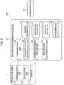
- FIG. 2 is a flowchart illustrating a procedure of the malfunction determination processing by the malfunction determination device 3.
- the malfunction determination unit 27 acquires the sensor data accumulated in the sensor information database 29.
- the malfunction determination unit 27 acquires a piece of data for one of the periods preliminarily divided at regular intervals.
- the data to be acquired includes a disturbance torque and a vibration value of the rotating mechanism.
- the malfunction determination unit 27 also acquires the maintenance history data of the production robot 1 from the maintenance history database 31.
- the maintenance history to be acquired includes a date of replacement of the reducer and a time and date of grease reapplication.
- the malfunction determination unit 27 does not necessarily acquire the sensor data from the sensor information database 29, and may acquire the sensor data from the production robot 1 in real time.
- the malfunction determination unit 27 calculates the malfunction determination value by use of the sensor data.
- the malfunction determination value is a statistical value to be calculated for determining a malfunction of the production robot 1. For example, when the data of the disturbance torque is selected from the sensor data, the difference rate of the disturbance torque is used as the malfunction determination value. The difference rate of the vibration value of the rotating mechanism may also be used as the malfunction determination value. Any other statistical value such as an average value enabling the determination of a malfunction of the production robot 1 may be used instead of the difference rate.
- the difference rate is a rate of change of a measurement value with respect to a predetermined reference value.
- the reference value may be an average value of disturbance torques in the same month of the previous year, for example. Any other value that can be a reference for determining a malfunction of the production robot 1 may be used as the reference value. For example, an average value of disturbance torques during the operation stop period may be used as the reference value when the production robot 1 is used in a region with no change in season or temperature.
- step S105 the malfunction determination unit 27 compares the malfunction determination value with a predetermined threshold so as to determine whether the production robot 1 has a malfunction. For example, as shown in Fig. 3 , when the difference rate of the disturbance torque is used as the malfunction determination value while the threshold is set to 20%, the production robot 1 is determined to have a malfunction when the difference rate of the disturbance torque is 20% or greater. The process proceeds to step S107 when there is a malfunction. The production robot 1 is determined to have no malfunction when the difference rate is less than 20%. The process returns to step S 101 when there is no malfunction so as to acquire the sensor data for the period subsequent to the current malfunction determination to continuously execute the malfunction determination.
- a predetermined threshold For example, as shown in Fig. 3 , when the difference rate of the disturbance torque is used as the malfunction determination value while the threshold is set to 20%, the production robot 1 is determined to have a malfunction when the difference rate of the disturbance torque is 20% or greater. The process proceeds to step S107 when there is a malfunction. The production robot 1 is determined to have no malfunction when the difference
- step S107 the operation status determination unit 23 acquires the operation history data of the production robot 1 from the operation history database 33.
- the operation history data to be acquired includes the operation start time and date and the operation stop time and date of the production robot 1.
- step S109 the operation status determination unit 23 determines whether there is any operation stop period during which the production robot 1 has stopped its operation for a predetermined period of time or longer based on the acquired operation history data.
- the operation status determination unit 23 acquires the operation start time and date and the operation stop time and date of the production robot 1 from the operation history database 33 to calculate the operation stop period, and determines whether the operation stop period is a predetermined period or longer. Examples of predetermined periods to be set include six hours, two days, ten days, and twenty days.
- the operation status determination unit 23 thus determines that there is the operation stop period when the production robot 1 is determined to have stopped the operation for six hours or longer.
- the process proceeds to step S111 when the production robot 1 is determined to have the operation stop period.
- the process proceeds to step 115 when the production robot 1 is determined to have no operation stop period.
- the suspension period setting unit 25 sets the malfunction determination suspension period during which the determination of a malfunction of the production robot 1 is suspended, depending on the length of the operation stop period. As shown in Fig. 4 , the suspension period setting unit 25 sets the malfunction determination suspension period to be one hour when the operation stop period is six hours or longer and shorter than two days. Similarly, the suspension period setting unit 25 sets the malfunction determination suspension period to be half a day when the operation stop period is two days or longer and shorter than ten days, sets the malfunction determination suspension period to be two days when the operation stop period is ten days or longer and shorter than twenty days, and sets the malfunction determination suspension period to be five days when the operation stop period is twenty days or longer.
- the suspension period setting unit 25 thus sets the malfunction determination suspension period to be longer as the operation stop period is longer.
- the length of the malfunction determination suspension period should have an upper limit so as not to allow the malfunction determination suspension period to exceed the upper limit even if the operation stop period is further extended. For example, the malfunction determination suspension period still needs to be set to five days if the operation stop period exceeds one month.
- the malfunction determination suspension period is set immediately after the operation stop period, namely, set from the point at which the production robot 1 starts operating after the operation stop period ends.
- Fig. 3 illustrates a case in which the operation stop period for two days ends, the malfunction determination suspension period L1 is set to half a day from the point at which the production robot 1 starts operating on July 4th.
- step S113 the malfunction determination unit 27 compares the malfunction determination value with the predetermined threshold in the period other than the malfunction determination suspension period so as to determine whether the production robot 1 has a malfunction. For example, the malfunction determination unit 27 determines whether the production robot 1 has a malfunction in the period other than the malfunction determination suspension period L1 set as shown in Fig. 3 . In other words, the malfunction determination unit 27 determines whether the production robot 1 has a malfunction by use of the sensor data detected in the period other than the malfunction determination suspension period L1.
- the difference rate of the disturbance torque used as the malfunction determination value exceeds the threshold of 20% in the malfunction determination suspension period L1.
- the malfunction determination value does not exceed the threshold of 20% in the period other than the malfunction determination suspension period L1.
- the malfunction determination unit 27 thus determines that the production robot 1 has no malfunction.
- the process returns to step S101 when there is no malfunction, so as to acquire the sensor data for the period subsequent to the current malfunction determination to continuously execute the following malfunction determination.
- the process proceeds to step S115 when there is a malfunction.
- the malfunction determination unit 27 may analyze any other factor, in addition to the waveform of the malfunction determination value shown in Fig. 3 , so as to determine a malfunction of the production robot 1 with the analysis result taken into consideration. For example, the malfunction determination unit 27 may execute the malfunction determination by use of another false-alarm avoidance logic, so as to determine a malfunction of the production robot 1 in accordance with the determination result.
- step S115 the malfunction determination unit 27 outputs an alarm via the user interface 5.
- the malfunction determination unit 27 causes the user interface 5 to display the determination result of the malfunction or an alert picture on the display screen, or outputs an alarm sound.
- the malfunction determination unit 27 then stores the determination result of the malfunction and the output record of the alarm in the database, so that the malfunction determination processing by the malfunction determination device 3 according to the present embodiment ends.
- the malfunction determination method and device determines whether the production machine has an operation stop period during which the production machine has stopped its operation for a predetermined period of time or longer in accordance with the operation history of the production machine.
- the malfunction determination suspension period for suspending the malfunction determination of the production machine is set in accordance with the length of the operation stop period, and the production machine is then determined whether to have a malfunction in the period other than the malfunction determination suspension period.
- the malfunction determination method and device thus can prevent false detection of a malfunction made under the circumstances having no relationship with the operational condition of the motor, such as when the production machine has not been operated for a long period of time.
- the malfunction determination method and device determines whether the production machine has a malfunction in the period other than the malfunction determination suspension period, so as to prevent false detection of a malfunction as described above.
- the prevention of false detection can decrease the number of maintenance steps necessary for the production machine, leading to a reduction in maintenance cost accordingly.
- the malfunction determination method and device sets the reference value based on the past sensor data so as to determine a malfunction of the production machine depending on whether the rate of change of the sensor data with respect to the reference value is a predetermined threshold or greater.
- the production machine can be determined to have a malfunction when the production machine has been greatly changed from the past state, so as to make a determination of a malfunction of the production machine more precisely. The precise determination can prevent false detection of a malfunction of the production machine more accurately.
- the malfunction determination method and device stores the sensor data in the database, and acquires the sensor data stored in the database so as to determine a malfunction of the production machine. This enables the malfunction determination at optional timing after all data necessary for the malfunction determination is prepared.
- the malfunction determination method and device thus can make a determination of a malfunction of the production machine more precisely, so as to prevent false detection of a malfunction of the production machine more accurately.
- the malfunction determination method and device uses the data of the disturbance torque applied to the motor as the sensor data used for the malfunction determination of the production machine.
- the determination of a malfunction of the production machine is executed in accordance with the result of sensing of the motor itself, so as to make a determination of a malfunction of the production machine more precisely.
- the precise determination can prevent false detection of a malfunction of the production machine more accurately.
- the malfunction determination method and device uses the data of the vibration value of the rotating mechanism as the sensor data used for the malfunction determination of the production machine.
- the determination of a malfunction of the production machine is executed in accordance with the result of sensing of the motor on the output side, so as to make a determination of a malfunction of the production machine more precisely.
- the precise determination can prevent false detection of a malfunction of the production machine more accurately.
- Fig. 5 is a block diagram illustrating a configuration of a malfunction determination system including a malfunction determination device according to the present embodiment. As shown in Fig. 5 , the present embodiment differs from the first embodiment in that the malfunction determination device 3 further includes an environmental temperature database 51.
- the environmental temperature database 51 accumulates environmental temperature data of the production robot 1. While the present embodiment exemplifies the environmental temperature data which refers to the temperature of the production robot 1, the data does not necessarily concern the temperature of the production robot 1, and may refer to the temperature of a facility in which the production robot 1 is installed. Alternatively, the temperature in an area in which the facility is located may be acquired externally, such as on the Internet, for example and accumulated.
- the suspension period setting unit 25 sets a malfunction determination suspension period for suspending the malfunction determination of the production robot 1 in accordance with the length of the operation stop period and the environmental temperature of the production robot 1. While the first embodiment is illustrated with the case of setting the malfunction determination suspension period only based on the length of the operation stop period, the suspension period setting unit 25 according to the present embodiment sets the malfunction determination suspension period based on both the length of the operation stop period and the environmental temperature of the production robot 1.
- the environmental temperature of the production robot 1 used for setting the malfunction determination suspension period is an average temperature of the production robot 1 in the operation stop period.
- the environmental temperature may be any of the average temperature of the production robot 1, the average temperature in the facility, and the average temperature in the area in which the facility is located.
- the suspension period setting unit 25 sets the malfunction determination suspension period depending on the length of the operation stop period and the environmental temperature of the production machine. In particular, the suspension period setting unit 25 sets the malfunction determination suspension period to be longer as the operation stop period is longer, and sets the malfunction determination suspension period to be longer as the environmental temperature is lower.
- the malfunction determination suspension period is set to two hours when the operation stop period of the production robot 1 is six hours or longer and shorter than two days at the environmental temperature of 10°C, and set to one hour at the environmental temperature of 30°C.
- the malfunction determination suspension period is set to one day when the operation stop period of the production robot 1 is two days or longer and shorter than ten days at the environmental temperature of 10°C, and set to half a day at the environmental temperature of 30°C.
- the malfunction determination suspension period is set to five days when the operation stop period of the production robot 1 is ten days or longer and shorter than twenty days at the environmental temperature of 10°C, and set to two days at the environmental temperature of 30°C.
- the malfunction determination suspension period is set to ten days when the operation stop period of the production robot 1 is twenty days or longer at the environmental temperature of 10°C, and set to five days at the environmental temperature of 30°C.
- the suspension period setting unit 25 thus sets the malfunction determination suspension period to be longer as the operation stop period is longer, and sets the malfunction determination suspension period to be longer as the environmental temperature is lower.
- Fig. 7 illustrates a case of setting the malfunction determination suspension period L1 to half a day when the operation stop period is two days and the environmental temperature is around 30°C.
- Fig. 8 illustrates a case of setting the malfunction determination suspension period L2 to one day when the operation stop period is two days and the environmental temperature is around 10°C.
- Fig. 6 illustrates the case in which the malfunction determination suspension period differs depending on the environmental temperature of 10°C or 30°C
- the malfunction determination suspension period to be set may differ depending on the seasons, instead of the environmental temperature.
- the malfunction determination suspension period to be set may differ between summer and winter, or may differ between spring, summer, fall, and winter.
- a malfunction determination method by the malfunction determination device 3 according to the present embodiment is described below.
- the malfunction determination processing according to the present embodiment is similar to the malfunction determination processing according to the first embodiment as illustrated in Fig. 2 .
- the operation status determination unit 23 according to the first embodiment only acquires the operation history data in step S107.
- the operation status determination unit 23 acquires the operation history data of the production robot 1 from the operation history database 33
- the suspension period setting unit 25 acquires the environmental temperature data of the production robot 1 from the environmental temperature database 51.
- step S111 the suspension period setting unit 25 sets the malfunction determination suspension period in accordance with the length of the operation stop period and the environmental temperature of the production machine, as described above.
- the other steps are the same as those in the first embodiment, and the malfunction determination processing by the malfunction determination device 3 thus ends.
- the malfunction determination method and device sets the malfunction determination suspension period in accordance with the length of the operation stop period and the environmental temperature of the production machine. This enables the setting of the malfunction determination suspension period with the influence by the temperature taken into consideration, so as to prevent false detection of a malfunction of the production machine more accurately.
- the malfunction determination method and device uses the average temperature of the production machine in the operation stop period as the environmental temperature of the production machine. This enables the setting of the malfunction determination suspension period while reflecting the condition of the production machine in the operation stop period, so as to prevent false detection of a malfunction of the production machine more accurately.
Landscapes
- Engineering & Computer Science (AREA)
- Robotics (AREA)
- Mechanical Engineering (AREA)
- Human Computer Interaction (AREA)
- Physics & Mathematics (AREA)
- General Physics & Mathematics (AREA)
- Automation & Control Theory (AREA)
- Manufacturing & Machinery (AREA)
- Manipulator (AREA)
- Control Of Electric Motors In General (AREA)
Claims (8)
- Fehlfunktionsbestimmungsverfahren einer Fehlfunktionsbestimmungsvorrichtung (3) zum Bestimmen einer Fehlfunktion einer Produktionsmaschine (1) mit einem Motorantriebssystem, das einen Motor als Antriebsquelle eines Drehmechanismus aufweist, wobei das Verfahren folgende Schritte aufweist:Erfassen von Sensordaten eines Sensors (11) zum Detektieren eines Zustandes des motorischen Antriebssystems;Bestimmen, ob die Produktionsmaschine (1) eine Betriebsstoppperiode aufweist, während der die Produktionsmaschine (1) ihren Betrieb für eine vorgegebene Zeitspanne oder länger in Übereinstimmung mit einer Betriebsgeschichte der Produktionsmaschine (1) gestoppt hat;wenn bestimmt wird, dass die Betriebsunterbrechungsperiode vorliegt, Einstellen einer Fehlfunktionsbestimmungs-Aussetzungsperiode zum Aussetzen einer Fehlfunktionsbestimmung der Produktionsmaschine (1), so dass sie länger ist, wenn die Betriebsunterbrechungsperiode länger ist, wobei die Länge der Fehlfunktionsbestimmungs-Aussetzungsperiode eine obere Grenze hat, um nicht zuzulassen, dass die Fehlfunktionsbestimmungs-Aussetzungsperiode die obere Grenze überschreitet, selbst wenn die Betriebsunterbrechungsperiode sich weiter erstreckt; undBestimmen, ob die Produktionsmaschine (1) eine Fehlfunktion in einer anderen Periode als der Fehlfunktionsbestimmungs-Aussetzungsperiode hat, durch Benutzen der Sensordaten für die andere Periode als die Fehlfunktionsbestimmungs-Aussetzungsperiode.
- Verfahren zur Fehlfunktionsbestimmung nach Anspruch 1, wobei die Fehlfunktionsbestimmungs-Aussetzungsperiode in Abhängigkeit von der Länge der Betriebsunterbrechungsperiode und einer Umgebungstemperatur der Produktionsmaschine (1) eingestellt wird.
- Verfahren zur Fehlfunktionsbestimmung nach Anspruch 2, wobei die Umgebungstemperatur der Produktionsmaschine (1) eine durchschnittliche Temperatur der Produktionsmaschine (1) während der Betriebsunterbrechungsperiode ist.
- Verfahren zur Fehlfunktionsbestimmung nach einem der Ansprüche 1 bis 3, wobei die Fehlfunktionsbestimmung der Produktionsmaschine (1) durch Einstellen eines Referenzwertes basierend auf vergangenen Sensordaten und Bestimmen, ob eine Änderungsrate der Sensordaten in Bezug auf den Referenzwert ein vorgegebener Schwellenwert oder größer ist, durchgeführt wird.
- Verfahren zur Fehlfunktionsbestimmung nach einem der Ansprüche 1 bis 4, ferner aufweisend das Speichern der Sensordaten in einer Datenbank (29) und das Erfassen der in der Datenbank (29) gespeicherten Sensordaten, um die Fehlfunktionsbestimmung der Produktionsmaschine (1) durchzuführen.
- Verfahren zur Fehlfunktionsbestimmung nach einem der Ansprüche 1 bis 5, wobei die für die Fehlfunktionsbestimmung der Produktionsmaschine (1) benutzten Sensordaten Daten eines auf den Motor zugeführten Störmoments sind.
- Verfahren zur Fehlfunktionsbestimmung nach einem der Ansprüche 1 bis 5, wobei als Sensordaten für die Fehlfunktionsbestimmung der Produktionsmaschine (1) Daten eines Schwingungswertes des Drehmechanismus benutzt werden.
- Fehlfunktionsbestimmungsvorrichtung (3) zur Bestimmung einer Fehlfunktion einer Produktionsmaschine (1) mit einem motorischen System, das einen Motor als Antriebsquelle eines Drehmechanismus aufweist, wobei die Vorrichtung konfiguriert ist zum:Erfassen von Sensordaten eines Sensors (11) zur Detektion eines Zustands des motorischen Antriebssystems;Bestimmen, ob die Produktionsmaschine (1) eine Betriebsstoppperiode aufweist, während der die Produktionsmaschine (1) ihren Betrieb für eine vorgegebene Zeitspanne oder länger in Übereinstimmung mit einer Betriebsgeschichte der Produktionsmaschine (1) gestoppt hat;wenn bestimmt wird, dass die Betriebsunterbrechungsperiode vorliegt, eine Fehlfunktionsbestimmungs-Aussetzungsperiode zum Aussetzen einer Fehlfunktionsbestimmung der Produktionsmaschine (1) so einzustellen, dass sie länger ist, wenn die Betriebsunterbrechungsperiode länger ist, wobei die Länge der Fehlfunktionsbestimmungs-Aussetzungsperiode eine obere Grenze hat, um nicht zuzulassen, dass die Fehlfunktionsbestimmungs-Aussetzungsperiode die obere Grenze überschreitet, selbst wenn die Betriebsunterbrechungsperiode weiter erstreckt wird; undBestimmen, ob die Produktionsmaschine (1) eine Fehlfunktion in einer anderen Periode als der Fehlfunktionsbestimmungs-Aussetzungsperiode hat, indem die Sensordaten für die andere Periode als die Fehlfunktionsbestimmungs-Aussetzungsperiode benutzt werden.
Applications Claiming Priority (1)
| Application Number | Priority Date | Filing Date | Title |
|---|---|---|---|
| PCT/JP2017/046666 WO2019130430A1 (ja) | 2017-12-26 | 2017-12-26 | 異常判定方法及び異常判定装置 |
Publications (3)
| Publication Number | Publication Date |
|---|---|
| EP3733361A1 EP3733361A1 (de) | 2020-11-04 |
| EP3733361A4 EP3733361A4 (de) | 2020-12-23 |
| EP3733361B1 true EP3733361B1 (de) | 2023-08-23 |
Family
ID=67066821
Family Applications (1)
| Application Number | Title | Priority Date | Filing Date |
|---|---|---|---|
| EP17936814.7A Active EP3733361B1 (de) | 2017-12-26 | 2017-12-26 | Verfahren zur bestimmung einer fehlfunktion und vorrichtung zur bestimmung einer fehlfunktion |
Country Status (6)
| Country | Link |
|---|---|
| US (1) | US11518034B2 (de) |
| EP (1) | EP3733361B1 (de) |
| JP (1) | JP6852811B2 (de) |
| CN (1) | CN111511509B (de) |
| MX (1) | MX2020006692A (de) |
| WO (1) | WO2019130430A1 (de) |
Families Citing this family (4)
| Publication number | Priority date | Publication date | Assignee | Title |
|---|---|---|---|---|
| JP2021096639A (ja) * | 2019-12-17 | 2021-06-24 | キヤノン株式会社 | 制御方法、制御装置、機械設備、制御プログラム、記録媒体 |
| CN113110362A (zh) * | 2021-05-24 | 2021-07-13 | 深创高新产业研究中心(深圳)有限公司 | 一种基于工业4.0的注塑设备状态监控系统 |
| US11462324B1 (en) | 2021-08-21 | 2022-10-04 | Ix Innovation Llc | Surgical equipment monitoring |
| JP7815788B2 (ja) * | 2022-01-21 | 2026-02-18 | 日産自動車株式会社 | 故障診断方法及び故障診断装置 |
Citations (2)
| Publication number | Priority date | Publication date | Assignee | Title |
|---|---|---|---|---|
| US20070244609A1 (en) * | 2006-04-17 | 2007-10-18 | Fanuc Ltd | Device and method for controlling electric motor |
| US20190099886A1 (en) * | 2017-09-29 | 2019-04-04 | Intel Corporation | Methods and apparatus for monitoring robot health in manufacturing environments |
Family Cites Families (14)
| Publication number | Priority date | Publication date | Assignee | Title |
|---|---|---|---|---|
| EP0766154B1 (de) * | 1992-12-28 | 2000-03-29 | Mitsubishi Denki Kabushiki Kaisha | Numerisch gesteuerte Werkzeugmaschine und Verfahren |
| JP2002175104A (ja) * | 2000-12-05 | 2002-06-21 | Murata Mach Ltd | 異常負荷監視機能付き工作機械 |
| JP4182082B2 (ja) * | 2005-04-18 | 2008-11-19 | ファナック株式会社 | 工作機械 |
| JP2007219991A (ja) | 2006-02-20 | 2007-08-30 | Fanuc Ltd | 異常負荷検出装置 |
| JP4335286B2 (ja) * | 2008-02-08 | 2009-09-30 | ファナック株式会社 | 部品保護機能を備えたロボット制御装置及びロボット制御方法 |
| WO2009142006A1 (ja) * | 2008-05-21 | 2009-11-26 | パナソニック株式会社 | ロボットの異常判定方法 |
| JP5167237B2 (ja) * | 2009-12-24 | 2013-03-21 | トヨタ自動車株式会社 | 回転センサの異常判定装置 |
| EP2572838A1 (de) * | 2010-08-31 | 2013-03-27 | Kabushiki Kaisha Yaskawa Denki | Roboter, Robotersystem, Robotersteuerungsvorrichtung und Statusbestimmungsverfahren |
| JP5902747B2 (ja) * | 2014-04-30 | 2016-04-13 | ファナック株式会社 | 加工再開準備機能を有するレーザ加工システム |
| JP6378112B2 (ja) | 2015-03-02 | 2018-08-22 | 日立オートモティブシステムズ株式会社 | 回転検出異常診断装置及び方法とそれを用いた回転位置制御装置 |
| ES2763004T3 (es) * | 2015-05-25 | 2020-05-26 | Nissan Motor | Dispositivo de diagnóstico de fallos y método de diagnóstico de fallos |
| EP3305483B1 (de) * | 2015-05-29 | 2020-12-30 | Nissan Motor Co., Ltd. | Vorrichtung und verfahren zur fehlerdiagnose |
| JP7028541B2 (ja) * | 2015-07-17 | 2022-03-02 | コマツ産機株式会社 | プレスシステムおよびプレスシステムの制御方法 |
| CN105204436B (zh) * | 2015-08-26 | 2016-10-26 | 山东省计算中心(国家超级计算济南中心) | 基于分级预警的数控机床故障诊断方法 |
-
2017
- 2017-12-26 EP EP17936814.7A patent/EP3733361B1/de active Active
- 2017-12-26 US US16/958,270 patent/US11518034B2/en active Active
- 2017-12-26 CN CN201780097993.0A patent/CN111511509B/zh active Active
- 2017-12-26 JP JP2019561434A patent/JP6852811B2/ja active Active
- 2017-12-26 WO PCT/JP2017/046666 patent/WO2019130430A1/ja not_active Ceased
- 2017-12-26 MX MX2020006692A patent/MX2020006692A/es unknown
Patent Citations (2)
| Publication number | Priority date | Publication date | Assignee | Title |
|---|---|---|---|---|
| US20070244609A1 (en) * | 2006-04-17 | 2007-10-18 | Fanuc Ltd | Device and method for controlling electric motor |
| US20190099886A1 (en) * | 2017-09-29 | 2019-04-04 | Intel Corporation | Methods and apparatus for monitoring robot health in manufacturing environments |
Also Published As
| Publication number | Publication date |
|---|---|
| JPWO2019130430A1 (ja) | 2020-12-03 |
| CN111511509A (zh) | 2020-08-07 |
| EP3733361A4 (de) | 2020-12-23 |
| US11518034B2 (en) | 2022-12-06 |
| CN111511509B (zh) | 2022-10-14 |
| US20200331145A1 (en) | 2020-10-22 |
| MX2020006692A (es) | 2020-09-03 |
| JP6852811B2 (ja) | 2021-03-31 |
| WO2019130430A1 (ja) | 2019-07-04 |
| EP3733361A1 (de) | 2020-11-04 |
Similar Documents
| Publication | Publication Date | Title |
|---|---|---|
| EP3305482B1 (de) | Fehlerdiagnosevorrichtung und fehlerdiagnoseverfahren | |
| EP3733361B1 (de) | Verfahren zur bestimmung einer fehlfunktion und vorrichtung zur bestimmung einer fehlfunktion | |
| EP3299133B1 (de) | Fehlerdiagnosevorrichtung und fehlerdiagnoseverfahren | |
| CN107614217B (zh) | 故障诊断装置及故障诊断方法 | |
| US7030746B2 (en) | Method and system for generating automatic alarms based on trends detected in machine operation | |
| EP3778157B1 (de) | Fehlerdiagnosevorrichtung und fehlerdiagnoseverfahren | |
| US20170178015A1 (en) | Maintenance timing prediction system and maintenance timing prediction device | |
| US20190378394A1 (en) | Production device on-line maintenance system and method | |
| CN111819042A (zh) | 异常检测装置及异常检测方法 | |
| US7249287B2 (en) | Methods and apparatus for providing alarm notification | |
| CN111837081A (zh) | 一种对驱动部的精准预维护方法 | |
| CN113970384A (zh) | 一种温度变化趋势报警方法及系统 | |
| JP2025130723A (ja) | 動機械振動モニタリングシステムおよび動機械振動モニタリング方法 | |
| CN119758857A (zh) | 基于伺服驱动器的报警显示方法、装置、设备及介质 |
Legal Events
| Date | Code | Title | Description |
|---|---|---|---|
| STAA | Information on the status of an ep patent application or granted ep patent |
Free format text: STATUS: THE INTERNATIONAL PUBLICATION HAS BEEN MADE |
|
| PUAI | Public reference made under article 153(3) epc to a published international application that has entered the european phase |
Free format text: ORIGINAL CODE: 0009012 |
|
| STAA | Information on the status of an ep patent application or granted ep patent |
Free format text: STATUS: REQUEST FOR EXAMINATION WAS MADE |
|
| 17P | Request for examination filed |
Effective date: 20200724 |
|
| AK | Designated contracting states |
Kind code of ref document: A1 Designated state(s): AL AT BE BG CH CY CZ DE DK EE ES FI FR GB GR HR HU IE IS IT LI LT LU LV MC MK MT NL NO PL PT RO RS SE SI SK SM TR |
|
| AX | Request for extension of the european patent |
Extension state: BA ME |
|
| A4 | Supplementary search report drawn up and despatched |
Effective date: 20201120 |
|
| RIC1 | Information provided on ipc code assigned before grant |
Ipc: B25J 19/06 20060101AFI20201116BHEP Ipc: B25J 9/16 20060101ALI20201116BHEP Ipc: G05B 19/4062 20060101ALI20201116BHEP |
|
| DAV | Request for validation of the european patent (deleted) | ||
| DAX | Request for extension of the european patent (deleted) | ||
| RAP3 | Party data changed (applicant data changed or rights of an application transferred) |
Owner name: RENAULT S.A.S Owner name: NISSAN MOTOR CO., LTD. |
|
| STAA | Information on the status of an ep patent application or granted ep patent |
Free format text: STATUS: EXAMINATION IS IN PROGRESS |
|
| 17Q | First examination report despatched |
Effective date: 20220311 |
|
| RAP3 | Party data changed (applicant data changed or rights of an application transferred) |
Owner name: RENAULT S.A.S Owner name: NISSAN MOTOR CO., LTD. |
|
| REG | Reference to a national code |
Ref country code: DE Ref legal event code: R079 Free format text: PREVIOUS MAIN CLASS: B25J0019060000 Ipc: B25J0009160000 Ref document number: 602017073290 Country of ref document: DE |
|
| GRAP | Despatch of communication of intention to grant a patent |
Free format text: ORIGINAL CODE: EPIDOSNIGR1 |
|
| STAA | Information on the status of an ep patent application or granted ep patent |
Free format text: STATUS: GRANT OF PATENT IS INTENDED |
|
| RIC1 | Information provided on ipc code assigned before grant |
Ipc: G05B 23/02 20060101ALI20230504BHEP Ipc: G05B 19/4062 20060101ALI20230504BHEP Ipc: B25J 9/16 20060101AFI20230504BHEP |
|
| INTG | Intention to grant announced |
Effective date: 20230525 |
|
| GRAS | Grant fee paid |
Free format text: ORIGINAL CODE: EPIDOSNIGR3 |
|
| GRAA | (expected) grant |
Free format text: ORIGINAL CODE: 0009210 |
|
| STAA | Information on the status of an ep patent application or granted ep patent |
Free format text: STATUS: THE PATENT HAS BEEN GRANTED |
|
| AK | Designated contracting states |
Kind code of ref document: B1 Designated state(s): AL AT BE BG CH CY CZ DE DK EE ES FI FR GB GR HR HU IE IS IT LI LT LU LV MC MK MT NL NO PL PT RO RS SE SI SK SM TR |
|
| REG | Reference to a national code |
Ref country code: GB Ref legal event code: FG4D |
|
| REG | Reference to a national code |
Ref country code: CH Ref legal event code: EP |
|
| REG | Reference to a national code |
Ref country code: DE Ref legal event code: R096 Ref document number: 602017073290 Country of ref document: DE |
|
| REG | Reference to a national code |
Ref country code: IE Ref legal event code: FG4D |
|
| REG | Reference to a national code |
Ref country code: LT Ref legal event code: MG9D |
|
| REG | Reference to a national code |
Ref country code: NL Ref legal event code: MP Effective date: 20230823 |
|
| REG | Reference to a national code |
Ref country code: AT Ref legal event code: MK05 Ref document number: 1602036 Country of ref document: AT Kind code of ref document: T Effective date: 20230823 |
|
| PG25 | Lapsed in a contracting state [announced via postgrant information from national office to epo] |
Ref country code: GR Free format text: LAPSE BECAUSE OF FAILURE TO SUBMIT A TRANSLATION OF THE DESCRIPTION OR TO PAY THE FEE WITHIN THE PRESCRIBED TIME-LIMIT Effective date: 20231124 |
|
| PG25 | Lapsed in a contracting state [announced via postgrant information from national office to epo] |
Ref country code: IS Free format text: LAPSE BECAUSE OF FAILURE TO SUBMIT A TRANSLATION OF THE DESCRIPTION OR TO PAY THE FEE WITHIN THE PRESCRIBED TIME-LIMIT Effective date: 20231223 |
|
| PG25 | Lapsed in a contracting state [announced via postgrant information from national office to epo] |
Ref country code: SE Free format text: LAPSE BECAUSE OF FAILURE TO SUBMIT A TRANSLATION OF THE DESCRIPTION OR TO PAY THE FEE WITHIN THE PRESCRIBED TIME-LIMIT Effective date: 20230823 Ref country code: RS Free format text: LAPSE BECAUSE OF FAILURE TO SUBMIT A TRANSLATION OF THE DESCRIPTION OR TO PAY THE FEE WITHIN THE PRESCRIBED TIME-LIMIT Effective date: 20230823 Ref country code: PT Free format text: LAPSE BECAUSE OF FAILURE TO SUBMIT A TRANSLATION OF THE DESCRIPTION OR TO PAY THE FEE WITHIN THE PRESCRIBED TIME-LIMIT Effective date: 20231226 Ref country code: NO Free format text: LAPSE BECAUSE OF FAILURE TO SUBMIT A TRANSLATION OF THE DESCRIPTION OR TO PAY THE FEE WITHIN THE PRESCRIBED TIME-LIMIT Effective date: 20231123 Ref country code: NL Free format text: LAPSE BECAUSE OF FAILURE TO SUBMIT A TRANSLATION OF THE DESCRIPTION OR TO PAY THE FEE WITHIN THE PRESCRIBED TIME-LIMIT Effective date: 20230823 Ref country code: LV Free format text: LAPSE BECAUSE OF FAILURE TO SUBMIT A TRANSLATION OF THE DESCRIPTION OR TO PAY THE FEE WITHIN THE PRESCRIBED TIME-LIMIT Effective date: 20230823 Ref country code: LT Free format text: LAPSE BECAUSE OF FAILURE TO SUBMIT A TRANSLATION OF THE DESCRIPTION OR TO PAY THE FEE WITHIN THE PRESCRIBED TIME-LIMIT Effective date: 20230823 Ref country code: IS Free format text: LAPSE BECAUSE OF FAILURE TO SUBMIT A TRANSLATION OF THE DESCRIPTION OR TO PAY THE FEE WITHIN THE PRESCRIBED TIME-LIMIT Effective date: 20231223 Ref country code: HR Free format text: LAPSE BECAUSE OF FAILURE TO SUBMIT A TRANSLATION OF THE DESCRIPTION OR TO PAY THE FEE WITHIN THE PRESCRIBED TIME-LIMIT Effective date: 20230823 Ref country code: GR Free format text: LAPSE BECAUSE OF FAILURE TO SUBMIT A TRANSLATION OF THE DESCRIPTION OR TO PAY THE FEE WITHIN THE PRESCRIBED TIME-LIMIT Effective date: 20231124 Ref country code: FI Free format text: LAPSE BECAUSE OF FAILURE TO SUBMIT A TRANSLATION OF THE DESCRIPTION OR TO PAY THE FEE WITHIN THE PRESCRIBED TIME-LIMIT Effective date: 20230823 Ref country code: AT Free format text: LAPSE BECAUSE OF FAILURE TO SUBMIT A TRANSLATION OF THE DESCRIPTION OR TO PAY THE FEE WITHIN THE PRESCRIBED TIME-LIMIT Effective date: 20230823 |
|
| PG25 | Lapsed in a contracting state [announced via postgrant information from national office to epo] |
Ref country code: PL Free format text: LAPSE BECAUSE OF FAILURE TO SUBMIT A TRANSLATION OF THE DESCRIPTION OR TO PAY THE FEE WITHIN THE PRESCRIBED TIME-LIMIT Effective date: 20230823 |
|
| PG25 | Lapsed in a contracting state [announced via postgrant information from national office to epo] |
Ref country code: ES Free format text: LAPSE BECAUSE OF FAILURE TO SUBMIT A TRANSLATION OF THE DESCRIPTION OR TO PAY THE FEE WITHIN THE PRESCRIBED TIME-LIMIT Effective date: 20230823 |
|
| PG25 | Lapsed in a contracting state [announced via postgrant information from national office to epo] |
Ref country code: SM Free format text: LAPSE BECAUSE OF FAILURE TO SUBMIT A TRANSLATION OF THE DESCRIPTION OR TO PAY THE FEE WITHIN THE PRESCRIBED TIME-LIMIT Effective date: 20230823 Ref country code: RO Free format text: LAPSE BECAUSE OF FAILURE TO SUBMIT A TRANSLATION OF THE DESCRIPTION OR TO PAY THE FEE WITHIN THE PRESCRIBED TIME-LIMIT Effective date: 20230823 Ref country code: ES Free format text: LAPSE BECAUSE OF FAILURE TO SUBMIT A TRANSLATION OF THE DESCRIPTION OR TO PAY THE FEE WITHIN THE PRESCRIBED TIME-LIMIT Effective date: 20230823 Ref country code: EE Free format text: LAPSE BECAUSE OF FAILURE TO SUBMIT A TRANSLATION OF THE DESCRIPTION OR TO PAY THE FEE WITHIN THE PRESCRIBED TIME-LIMIT Effective date: 20230823 Ref country code: DK Free format text: LAPSE BECAUSE OF FAILURE TO SUBMIT A TRANSLATION OF THE DESCRIPTION OR TO PAY THE FEE WITHIN THE PRESCRIBED TIME-LIMIT Effective date: 20230823 Ref country code: CZ Free format text: LAPSE BECAUSE OF FAILURE TO SUBMIT A TRANSLATION OF THE DESCRIPTION OR TO PAY THE FEE WITHIN THE PRESCRIBED TIME-LIMIT Effective date: 20230823 Ref country code: SK Free format text: LAPSE BECAUSE OF FAILURE TO SUBMIT A TRANSLATION OF THE DESCRIPTION OR TO PAY THE FEE WITHIN THE PRESCRIBED TIME-LIMIT Effective date: 20230823 |
|
| REG | Reference to a national code |
Ref country code: DE Ref legal event code: R097 Ref document number: 602017073290 Country of ref document: DE |
|
| PG25 | Lapsed in a contracting state [announced via postgrant information from national office to epo] |
Ref country code: IT Free format text: LAPSE BECAUSE OF FAILURE TO SUBMIT A TRANSLATION OF THE DESCRIPTION OR TO PAY THE FEE WITHIN THE PRESCRIBED TIME-LIMIT Effective date: 20230823 |
|
| PLBE | No opposition filed within time limit |
Free format text: ORIGINAL CODE: 0009261 |
|
| STAA | Information on the status of an ep patent application or granted ep patent |
Free format text: STATUS: NO OPPOSITION FILED WITHIN TIME LIMIT |
|
| 26N | No opposition filed |
Effective date: 20240524 |
|
| PG25 | Lapsed in a contracting state [announced via postgrant information from national office to epo] |
Ref country code: SI Free format text: LAPSE BECAUSE OF FAILURE TO SUBMIT A TRANSLATION OF THE DESCRIPTION OR TO PAY THE FEE WITHIN THE PRESCRIBED TIME-LIMIT Effective date: 20230823 |
|
| REG | Reference to a national code |
Ref country code: CH Ref legal event code: PL |
|
| PG25 | Lapsed in a contracting state [announced via postgrant information from national office to epo] |
Ref country code: LU Free format text: LAPSE BECAUSE OF NON-PAYMENT OF DUE FEES Effective date: 20231226 |
|
| PG25 | Lapsed in a contracting state [announced via postgrant information from national office to epo] |
Ref country code: MC Free format text: LAPSE BECAUSE OF FAILURE TO SUBMIT A TRANSLATION OF THE DESCRIPTION OR TO PAY THE FEE WITHIN THE PRESCRIBED TIME-LIMIT Effective date: 20230823 |
|
| REG | Reference to a national code |
Ref country code: BE Ref legal event code: MM Effective date: 20231231 |
|
| PG25 | Lapsed in a contracting state [announced via postgrant information from national office to epo] |
Ref country code: MC Free format text: LAPSE BECAUSE OF FAILURE TO SUBMIT A TRANSLATION OF THE DESCRIPTION OR TO PAY THE FEE WITHIN THE PRESCRIBED TIME-LIMIT Effective date: 20230823 Ref country code: LU Free format text: LAPSE BECAUSE OF NON-PAYMENT OF DUE FEES Effective date: 20231226 |
|
| REG | Reference to a national code |
Ref country code: IE Ref legal event code: MM4A |
|
| PG25 | Lapsed in a contracting state [announced via postgrant information from national office to epo] |
Ref country code: IE Free format text: LAPSE BECAUSE OF NON-PAYMENT OF DUE FEES Effective date: 20231226 |
|
| PG25 | Lapsed in a contracting state [announced via postgrant information from national office to epo] |
Ref country code: BE Free format text: LAPSE BECAUSE OF NON-PAYMENT OF DUE FEES Effective date: 20231231 |
|
| PG25 | Lapsed in a contracting state [announced via postgrant information from national office to epo] |
Ref country code: CH Free format text: LAPSE BECAUSE OF NON-PAYMENT OF DUE FEES Effective date: 20231231 |
|
| PG25 | Lapsed in a contracting state [announced via postgrant information from national office to epo] |
Ref country code: IE Free format text: LAPSE BECAUSE OF NON-PAYMENT OF DUE FEES Effective date: 20231226 Ref country code: CH Free format text: LAPSE BECAUSE OF NON-PAYMENT OF DUE FEES Effective date: 20231231 Ref country code: BE Free format text: LAPSE BECAUSE OF NON-PAYMENT OF DUE FEES Effective date: 20231231 |
|
| PG25 | Lapsed in a contracting state [announced via postgrant information from national office to epo] |
Ref country code: BG Free format text: LAPSE BECAUSE OF FAILURE TO SUBMIT A TRANSLATION OF THE DESCRIPTION OR TO PAY THE FEE WITHIN THE PRESCRIBED TIME-LIMIT Effective date: 20230823 |
|
| PG25 | Lapsed in a contracting state [announced via postgrant information from national office to epo] |
Ref country code: BG Free format text: LAPSE BECAUSE OF FAILURE TO SUBMIT A TRANSLATION OF THE DESCRIPTION OR TO PAY THE FEE WITHIN THE PRESCRIBED TIME-LIMIT Effective date: 20230823 |
|
| PG25 | Lapsed in a contracting state [announced via postgrant information from national office to epo] |
Ref country code: CY Free format text: LAPSE BECAUSE OF FAILURE TO SUBMIT A TRANSLATION OF THE DESCRIPTION OR TO PAY THE FEE WITHIN THE PRESCRIBED TIME-LIMIT; INVALID AB INITIO Effective date: 20171226 |
|
| PG25 | Lapsed in a contracting state [announced via postgrant information from national office to epo] |
Ref country code: HU Free format text: LAPSE BECAUSE OF FAILURE TO SUBMIT A TRANSLATION OF THE DESCRIPTION OR TO PAY THE FEE WITHIN THE PRESCRIBED TIME-LIMIT; INVALID AB INITIO Effective date: 20171226 |
|
| PG25 | Lapsed in a contracting state [announced via postgrant information from national office to epo] |
Ref country code: TR Free format text: LAPSE BECAUSE OF FAILURE TO SUBMIT A TRANSLATION OF THE DESCRIPTION OR TO PAY THE FEE WITHIN THE PRESCRIBED TIME-LIMIT Effective date: 20230823 |
|
| PGFP | Annual fee paid to national office [announced via postgrant information from national office to epo] |
Ref country code: DE Payment date: 20251126 Year of fee payment: 9 |
|
| PGFP | Annual fee paid to national office [announced via postgrant information from national office to epo] |
Ref country code: GB Payment date: 20251119 Year of fee payment: 9 |
|
| PGFP | Annual fee paid to national office [announced via postgrant information from national office to epo] |
Ref country code: FR Payment date: 20251119 Year of fee payment: 9 |