EP3733479A1 - Hilfsmechanismus und elektrische servolenkung - Google Patents
Hilfsmechanismus und elektrische servolenkung Download PDFInfo
- Publication number
- EP3733479A1 EP3733479A1 EP18893546.4A EP18893546A EP3733479A1 EP 3733479 A1 EP3733479 A1 EP 3733479A1 EP 18893546 A EP18893546 A EP 18893546A EP 3733479 A1 EP3733479 A1 EP 3733479A1
- Authority
- EP
- European Patent Office
- Prior art keywords
- rotation
- transmission member
- electric motor
- coupling
- worm
- Prior art date
- Legal status (The legal status is an assumption and is not a legal conclusion. Google has not performed a legal analysis and makes no representation as to the accuracy of the status listed.)
- Granted
Links
Images







Classifications
-
- B—PERFORMING OPERATIONS; TRANSPORTING
- B62—LAND VEHICLES FOR TRAVELLING OTHERWISE THAN ON RAILS
- B62D—MOTOR VEHICLES; TRAILERS
- B62D5/00—Power-assisted or power-driven steering
- B62D5/04—Power-assisted or power-driven steering electrical, e.g. using an electric servo-motor connected to, or forming part of, the steering gear
- B62D5/0442—Conversion of rotational into longitudinal movement
- B62D5/0454—Worm gears
-
- F—MECHANICAL ENGINEERING; LIGHTING; HEATING; WEAPONS; BLASTING
- F16—ENGINEERING ELEMENTS AND UNITS; GENERAL MEASURES FOR PRODUCING AND MAINTAINING EFFECTIVE FUNCTIONING OF MACHINES OR INSTALLATIONS; THERMAL INSULATION IN GENERAL
- F16D—COUPLINGS FOR TRANSMITTING ROTATION; CLUTCHES; BRAKES
- F16D3/00—Yielding couplings, i.e. with means permitting movement between the connected parts during the drive
- F16D3/50—Yielding couplings, i.e. with means permitting movement between the connected parts during the drive with the coupling parts connected by one or more intermediate members
- F16D3/64—Yielding couplings, i.e. with means permitting movement between the connected parts during the drive with the coupling parts connected by one or more intermediate members comprising elastic elements arranged between substantially-radial walls of both coupling parts
- F16D3/68—Yielding couplings, i.e. with means permitting movement between the connected parts during the drive with the coupling parts connected by one or more intermediate members comprising elastic elements arranged between substantially-radial walls of both coupling parts the elements being made of rubber or similar material
-
- F—MECHANICAL ENGINEERING; LIGHTING; HEATING; WEAPONS; BLASTING
- F16—ENGINEERING ELEMENTS AND UNITS; GENERAL MEASURES FOR PRODUCING AND MAINTAINING EFFECTIVE FUNCTIONING OF MACHINES OR INSTALLATIONS; THERMAL INSULATION IN GENERAL
- F16D—COUPLINGS FOR TRANSMITTING ROTATION; CLUTCHES; BRAKES
- F16D3/00—Yielding couplings, i.e. with means permitting movement between the connected parts during the drive
- F16D3/50—Yielding couplings, i.e. with means permitting movement between the connected parts during the drive with the coupling parts connected by one or more intermediate members
- F16D3/54—Couplings comprising a chain or strip surrounding two wheels arranged side by side and provided with teeth or the equivalent
-
- F—MECHANICAL ENGINEERING; LIGHTING; HEATING; WEAPONS; BLASTING
- F16—ENGINEERING ELEMENTS AND UNITS; GENERAL MEASURES FOR PRODUCING AND MAINTAINING EFFECTIVE FUNCTIONING OF MACHINES OR INSTALLATIONS; THERMAL INSULATION IN GENERAL
- F16D—COUPLINGS FOR TRANSMITTING ROTATION; CLUTCHES; BRAKES
- F16D3/00—Yielding couplings, i.e. with means permitting movement between the connected parts during the drive
- F16D3/50—Yielding couplings, i.e. with means permitting movement between the connected parts during the drive with the coupling parts connected by one or more intermediate members
- F16D3/72—Yielding couplings, i.e. with means permitting movement between the connected parts during the drive with the coupling parts connected by one or more intermediate members with axially-spaced attachments to the coupling parts
- F16D3/74—Yielding couplings, i.e. with means permitting movement between the connected parts during the drive with the coupling parts connected by one or more intermediate members with axially-spaced attachments to the coupling parts the intermediate member or members being made of rubber or other rubber-like flexible material
-
- F—MECHANICAL ENGINEERING; LIGHTING; HEATING; WEAPONS; BLASTING
- F16—ENGINEERING ELEMENTS AND UNITS; GENERAL MEASURES FOR PRODUCING AND MAINTAINING EFFECTIVE FUNCTIONING OF MACHINES OR INSTALLATIONS; THERMAL INSULATION IN GENERAL
- F16H—GEARING
- F16H1/00—Toothed gearings for conveying rotary motion
- F16H1/02—Toothed gearings for conveying rotary motion without gears having orbital motion
- F16H1/04—Toothed gearings for conveying rotary motion without gears having orbital motion involving only two intermeshing members
- F16H1/12—Toothed gearings for conveying rotary motion without gears having orbital motion involving only two intermeshing members with non-parallel axes
- F16H1/16—Toothed gearings for conveying rotary motion without gears having orbital motion involving only two intermeshing members with non-parallel axes comprising worm and worm-wheel
-
- H—ELECTRICITY
- H02—GENERATION; CONVERSION OR DISTRIBUTION OF ELECTRIC POWER
- H02K—DYNAMO-ELECTRIC MACHINES
- H02K5/00—Casings; Enclosures; Supports
- H02K5/24—Casings; Enclosures; Supports specially adapted for suppression or reduction of noise or vibrations
-
- H—ELECTRICITY
- H02—GENERATION; CONVERSION OR DISTRIBUTION OF ELECTRIC POWER
- H02K—DYNAMO-ELECTRIC MACHINES
- H02K7/00—Arrangements for handling mechanical energy structurally associated with dynamo-electric machines, e.g. structural association with mechanical driving motors or auxiliary dynamo-electric machines
- H02K7/003—Couplings; Details of shafts
-
- H—ELECTRICITY
- H02—GENERATION; CONVERSION OR DISTRIBUTION OF ELECTRIC POWER
- H02K—DYNAMO-ELECTRIC MACHINES
- H02K7/00—Arrangements for handling mechanical energy structurally associated with dynamo-electric machines, e.g. structural association with mechanical driving motors or auxiliary dynamo-electric machines
- H02K7/10—Structural association with clutches, brakes, gears, pulleys or mechanical starters
- H02K7/116—Structural association with clutches, brakes, gears, pulleys or mechanical starters with gears
- H02K7/1163—Structural association with clutches, brakes, gears, pulleys or mechanical starters with gears where at least two gears have non-parallel axes without having orbital motion
- H02K7/1166—Structural association with clutches, brakes, gears, pulleys or mechanical starters with gears where at least two gears have non-parallel axes without having orbital motion comprising worm and worm-wheel
-
- B—PERFORMING OPERATIONS; TRANSPORTING
- B62—LAND VEHICLES FOR TRAVELLING OTHERWISE THAN ON RAILS
- B62D—MOTOR VEHICLES; TRAILERS
- B62D5/00—Power-assisted or power-driven steering
- B62D5/04—Power-assisted or power-driven steering electrical, e.g. using an electric servo-motor connected to, or forming part of, the steering gear
-
- B—PERFORMING OPERATIONS; TRANSPORTING
- B62—LAND VEHICLES FOR TRAVELLING OTHERWISE THAN ON RAILS
- B62D—MOTOR VEHICLES; TRAILERS
- B62D5/00—Power-assisted or power-driven steering
- B62D5/04—Power-assisted or power-driven steering electrical, e.g. using an electric servo-motor connected to, or forming part of, the steering gear
- B62D5/0409—Electric motor acting on the steering column
-
- F—MECHANICAL ENGINEERING; LIGHTING; HEATING; WEAPONS; BLASTING
- F16—ENGINEERING ELEMENTS AND UNITS; GENERAL MEASURES FOR PRODUCING AND MAINTAINING EFFECTIVE FUNCTIONING OF MACHINES OR INSTALLATIONS; THERMAL INSULATION IN GENERAL
- F16D—COUPLINGS FOR TRANSMITTING ROTATION; CLUTCHES; BRAKES
- F16D3/00—Yielding couplings, i.e. with means permitting movement between the connected parts during the drive
- F16D3/50—Yielding couplings, i.e. with means permitting movement between the connected parts during the drive with the coupling parts connected by one or more intermediate members
-
- F—MECHANICAL ENGINEERING; LIGHTING; HEATING; WEAPONS; BLASTING
- F16—ENGINEERING ELEMENTS AND UNITS; GENERAL MEASURES FOR PRODUCING AND MAINTAINING EFFECTIVE FUNCTIONING OF MACHINES OR INSTALLATIONS; THERMAL INSULATION IN GENERAL
- F16D—COUPLINGS FOR TRANSMITTING ROTATION; CLUTCHES; BRAKES
- F16D3/00—Yielding couplings, i.e. with means permitting movement between the connected parts during the drive
- F16D3/50—Yielding couplings, i.e. with means permitting movement between the connected parts during the drive with the coupling parts connected by one or more intermediate members
- F16D3/72—Yielding couplings, i.e. with means permitting movement between the connected parts during the drive with the coupling parts connected by one or more intermediate members with axially-spaced attachments to the coupling parts
-
- F—MECHANICAL ENGINEERING; LIGHTING; HEATING; WEAPONS; BLASTING
- F16—ENGINEERING ELEMENTS AND UNITS; GENERAL MEASURES FOR PRODUCING AND MAINTAINING EFFECTIVE FUNCTIONING OF MACHINES OR INSTALLATIONS; THERMAL INSULATION IN GENERAL
- F16H—GEARING
- F16H57/00—General details of gearing
- F16H57/0006—Vibration-damping or noise reducing means specially adapted for gearings
-
- H—ELECTRICITY
- H02—GENERATION; CONVERSION OR DISTRIBUTION OF ELECTRIC POWER
- H02K—DYNAMO-ELECTRIC MACHINES
- H02K21/00—Synchronous motors having permanent magnets; Synchronous generators having permanent magnets
- H02K21/12—Synchronous motors having permanent magnets; Synchronous generators having permanent magnets with stationary armatures and rotating magnets
- H02K21/14—Synchronous motors having permanent magnets; Synchronous generators having permanent magnets with stationary armatures and rotating magnets with magnets rotating within the armatures
-
- H—ELECTRICITY
- H02—GENERATION; CONVERSION OR DISTRIBUTION OF ELECTRIC POWER
- H02K—DYNAMO-ELECTRIC MACHINES
- H02K2213/00—Specific aspects, not otherwise provided for and not covered by codes H02K2201/00 - H02K2211/00
- H02K2213/03—Machines characterised by numerical values, ranges, mathematical expressions or similar information
Definitions
- the present invention relates to an assist mechanism and an electric power steering device.
- Patent Literature 1 Electric power steering devices for assisting torque necessary for steering a vehicle by an electric motor have been known (for example, Patent Literature 1).
- Patent Literature 1 Japanese Patent Application Laid-open No. 2005-067371
- an assist mechanism includes: an electric motor in which a rotor has a magnet and a stator has a winding; a shaft-shaped member in which a worm engaged with a worm wheel is formed; and a coupling that couples an output shaft of the electric motor and the shaft-shaped member to each other, wherein a smallest rotation order among rotation orders of the electric motor and a rotation order of the worm are prime to each other.
- an assist mechanism includes: an electric motor; a shaft-shaped member in which a worm engaged with a worm wheel is formed; and a coupling that couples an output shaft of the electric motor and the shaft-shaped member to each other, wherein a rotation order of the worm and a rotation order of the coupling are prime to each other.
- an assist mechanism includes: an electric motor in which a rotor has a magnet and a stator has a winding; a shaft-shaped member in which a worm engaged with a worm wheel is formed; and a coupling that couples an output shaft of the electric motor and the shaft-shaped member to each other, wherein a smallest rotation order among rotation orders of the electric motor and a rotation order of the worm are prime to each other, the smallest rotation order among the rotation orders of the electric motor and a rotation order of the coupling are prime to each other, and the rotation order of the worm and the rotation order of the coupling are prime to each other.
- an assist mechanism includes: an electric motor; a shaft-shaped member in which a worm engaged with a worm wheel is formed; and a coupling that couples an output shaft of the electric motor and the shaft-shaped member to each other, wherein a smallest rotation order among rotation orders of the electric motor and a rotation order of the coupling are prime to each other.
- an assist mechanism includes: an electric motor; a shaft-shaped member in which a worm engaged with a worm wheel is formed; and a coupling that couples an output shaft of the electric motor and the shaft-shaped member to each other, wherein at least two rotation orders of a smallest rotation order among rotation orders of the electric motor, a rotation order of the worm, and a rotation order of the coupling are different from each other.
- an electric power steering device includes the assist mechanism, wherein the worm wheel is provided to an output shaft of a steering wheel.
- the rotation orders of rotating configurations can be made different to shift their timings of occurrence of vibration and noise. This can prevent larger vibration and noise, which would otherwise be caused due to a synergistic effect created by concurrence of vibrations and noises of these configurations. Consequently, vibration and noise can be reduced.
- the rotation order of the electric motor is n times a larger natural number of two natural numbers other than 1 when a multiplication of the two natural numbers expresses the number of poles of a magnet in the rotor, n is a natural number of 1 or greater, and the rotation order of the worm is the number of teeth of the worm wheel that advance in response to one rotation of the shaft-shaped member.
- the rotation order of the worm is the number of teeth of the worm wheel that advance in response to one rotation of the shaft-shaped member
- the coupling includes a first transmission member fixed to the output shaft, a second transmission member fixed to the shaft-shaped member, and a third transmission member engaged with a predetermined number of projections of each of the first transmission member and the second transmission member to couple the first transmission member and the second transmission member to each other, and the rotation order of the coupling is the predetermined number.
- the rotation order of the electric motor is n times a larger natural number of two natural numbers other than 1 when a multiplication of the two natural numbers expresses the number of poles of a magnet in the rotor, n is a natural number of 1 or greater, the rotation order of the worm is the number of teeth of the worm wheel that advance in response to one rotation of the shaft-shaped member, the coupling includes a first transmission member fixed to the output shaft, a second transmission member fixed to the shaft-shaped member, and a third transmission member engaged with a predetermined number of projections of each of the first transmission member and the second transmission member to couple the first transmission member and the second transmission member to each other, and the rotation order of the coupling is the predetermined number.
- the rotation order of the electric motor is n times a larger natural number of two natural numbers other than 1 when a multiplication of the two natural numbers expresses the number of poles of a magnet or a commutator in the rotor, n is a natural number of 1 or greater, and the rotation order of the worm is the number of teeth of the worm wheel that advance in response to one rotation of the shaft-shaped member.
- the rotation order of the electric motor is n times a larger natural number of two natural numbers other than 1 when a multiplication of the two natural numbers expresses the number of poles of a magnet or a commutator in the rotor, n is a natural number of 1 or greater,
- the coupling includes a first transmission member fixed to the output shaft, a second transmission member fixed to the shaft-shaped member, and a third transmission member engaged with a predetermined number of projections of each of the first transmission member and the second transmission member to couple the first transmission member and the second transmission member to each other, and the rotation order of the coupling is the predetermined number.
- the rotation orders of the rotating configurations can be specified based on the number of configurations that move at positions away from the respective rotation axes along with the rotations of the rotating configurations, and the rotation orders can be made different. Therefore, their timings of occurrence of vibration and noise can be shifted. This can more reliably prevent larger vibration and noise, which would otherwise be caused due to a synergistic effect created by concurrence of vibrations and noises of these configurations. Consequently, vibration and noise can be more reliably reduced.
- the rotation order of the coupling is 5 or 7.
- the smallest rotation order among the rotation orders of the electric motor, the rotation order of the worm, and the rotation order of the coupling are different from one another.
- the coupling includes a first transmission member fixed to the output shaft, a second transmission member fixed to the shaft-shaped member, and a third transmission member engaged with five or seven projections of each of the first transmission member and the second transmission member to couple the first transmission member and the second transmission member to each other, and the rotation order of the coupling is the number of the projections.
- the rotation order of the coupling can be made difficult to be equal to the rotation orders of other configurations. This can more reliably prevent larger vibration and noise, which would otherwise be caused due to a synergistic effect created by concurrence of vibrations and noises of these configurations. Consequently, vibration and noise can be more reliably reduced.
- the smallest rotation order among the rotation orders of the electric motor is 3, the rotation order of the worm is 2, and the rotation order of the coupling is 5 or 7.
- the smallest rotation order among the rotation orders of the electric motor is 4, the rotation order of the worm is 3, and the rotation order of the coupling is 5 or 7.
- the smallest rotation orders among the rotation orders of the electric motor is 5
- the rotation order of the worm is 2
- the rotation order of the coupling is 7.
- the smallest rotation order among the rotation orders of the electric motor is 5
- the rotation order of the worm is 3
- the rotation order of the coupling is 4.
- vibration and noise can be reduced.
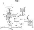
- FIG. 1 is a diagram illustrating a configuration example of an electric power steering device 80 including an assist mechanism 83 in a first embodiment.
- the electric power steering device 80 includes, in the order in which force applied by a steerer is transmitted, a steering wheel 81, a steering shaft 82, an assist mechanism 83, a universal joint 84, a lower shaft 85, a universal joint 86, a pinion shaft 87, a steering gear 88, and a tie rod 89.
- the electric power steering device 80 further includes an electronic control unit (ECU) 90, a torque sensor 91a, and a vehicle speed sensor 91b.
- ECU electronice control unit
- the steering shaft 82 includes an input shaft 82a and an output shaft 82b. One end portion of the input shaft 82a is coupled to the steering wheel 81, and the other end portion is coupled to the assist mechanism 83 through the torque sensor 91a. One end portion of the output shaft 82b is coupled to the assist mechanism 83, and the other end portion is coupled to the universal joint 84.
- the input shaft 82a and the output shaft 82b are formed from magnetic material such as iron.
- One end portion of the lower shaft 85 is coupled to the universal joint 84, and the other end portion is coupled to the universal joint 86.
- One end portion of the pinion shaft 87 is coupled to the universal joint 86, and the other end portion is coupled to the steering gear 88.
- the steering gear 88 includes a pinion 88a and a rack 88b.
- the pinion 88a is coupled to the pinion shaft 87.
- the rack 88b is engaged with the pinion 88a.
- the steering gear 88 is formed as a rack and pinion steering gear.
- the steering gear 88 converts rotational motion transmitted to the pinion 88a into linear motion by the rack 88b.
- the tie rod 89 is coupled to the rack 88b.
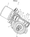
- FIG. 2 is a diagram illustrating a configuration example of the assist mechanism 83.
- FIG. 2 illustrates a diagram in which a part of a housing 93 is cut open for the purpose of illustrating an internal configuration of the housing 93.
- the assist mechanism 83 includes an electric motor 10, a housing 93, a worm gear shaft 94, a worm wheel 96, and a coupling 16.
- the housing 93 houses the worm gear shaft 94, the worm wheel 96, and the coupling 16 therein.
- the electric motor 10 is fixed to the housing 93.
- An output shaft 11 of the electric motor 10 extends inward of the housing 93.
- the electric motor 10 rotationally drives the output shaft 11.
- the output shaft 11 is coupled to the worm gear shaft 94 through the coupling 16.
- the worm gear shaft 94 rotates.
- the worm gear shaft 94 is engaged with the worm wheel 96.
- the worm wheel 96 rotates.
- the worm wheel 96 is fixed such that its rotation axis coincides with a rotation axis of the output shaft 82b.
- the assist mechanism 83 assists the rotation of the output shaft 82b with rotational driving force of the electric motor 10.
- the assist mechanism 83 applies, to the output shaft 82b, torque for assisting steering performed through the steering wheel 81.
- a steering column is formed using the steering shaft 82, the torque sensor 91a, and the assist mechanism 83.
- the electric power steering device 80 in the first embodiment is, for example, a column assist power steering device.
- the torque sensor 91a illustrated in FIG. 1 detects steering force of a driver transmitted to the input shaft 82a through the steering wheel 81 as steering torque.
- the vehicle speed sensor 91b detects traveling speed of a vehicle having the electric power steering device 80 mounted thereon.
- the ECU 90 is electrically connected to the electric motor 10, the torque sensor 91a, and the vehicle speed sensor 91b.
- the ECU 90 controls operation of the electric motor 10.
- the ECU 90 acquires signals from the torque sensor 91a and the vehicle speed sensor 91b. In other words, the ECU 90 acquires steering torque T from the torque sensor 91a, and acquires traveling speed V of the vehicle from the vehicle speed sensor 91b.
- the ECU 90 is supplied with power from a power supply device (for example, on-vehicle battery) 99 in the state in which an ignition switch 98 is turned on.
- the ECU 90 calculates an assist steering command value for assist command based on the steering torque T and the traveling speed V.
- the ECU 90 adjusts a power value X to be supplied to the electric motor 10 based on the calculated assist steering command value.
- the ECU 90 acquires, as operation information Y, information on induced voltage from the electric motor 10 or information on rotation of a rotor from a resolver described later.
- Steering force input to the steering wheel 81 by a steerer is transmitted to the assist mechanism 83 through the input shaft 82a.
- the ECU 90 acquires steering torque T input to the input shaft 82a from the torque sensor 91a, and acquires traveling speed V from the vehicle speed sensor 91b.
- the ECU 90 controls the operation of the electric motor 10. Assist steering torque produced by the electric motor 10 is transmitted to the assist mechanism 83.
- the steering torque T (including assist steering torque) output through the output shaft 82b is transmitted to the lower shaft 85 through the universal joint 84, and further transmitted to the pinion shaft 87 through the universal joint 86.
- the steering force transmitted to the pinion shaft 87 is transmitted to the tie rod 89 through the steering gear 88 to turn steered wheels.
- the worm gear shaft 94 is a shaft-shaped member including a worm 94a and a rotation shaft portion 94b.
- the rotation shaft portion 94b in the worm gear shaft 94 is pivotally supported by bearings 95a and 95b fixed to the housing 93.
- the bearings 95a and 95b pivotally support the worm gear shaft 94 such that the worm gear shaft 94 is rotatable.
- the worm 94a in the worm gear shaft 94 is formed between the bearing 95a and the bearing 95b.
- FIG. 3 is a diagram illustrating a configuration example of the worm 94a and the worm wheel 96 in the first embodiment.
- the worm 94a in the first embodiment is a double thread worm.
- gears of the worm wheel 96 are formed so as to advance by one in response to half rotation of the worm 94a.
- the gears of the worm wheel 96 advance by two in response to one rotation of the worm 94a.
- FIG. 4 is a diagram illustrating an example of a configuration near the coupling 16.
- the coupling 16 includes a first transmission member 17, a second transmission member 18, and a third transmission member 19.
- the first transmission member 17 is fixed to the output shaft 11.
- the first transmission member 17 draws a circular ring that houses therein an end portion of the output shaft 11 extending from the electric motor 10.
- the center of the circular ring of the first transmission member 17 coincides with a rotation axis center 11a (see FIG. 7 ) of the output shaft 11.
- the second transmission member 18 is fixed to the rotation shaft portion 94b.
- the second transmission member 18 draws a circular ring that houses therein an end portion of the rotation shaft portion 94b extending from the bearing 95a, which is located closer to the output shaft 11 and pivotally supports the worm gear shaft 94, toward the output shaft 11.
- the center of the circular ring of the second transmission member 18 coincides with a rotation axis center of the rotation shaft portion 94b.
- FIG. 5 is a perspective view of the coupling 16 in the first embodiment.
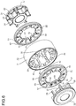
- FIG. 6 is an exploded perspective view of the coupling 16 in the first embodiment.
- the third transmission member 19 is engaged with a predetermined number of projections 24 of the first transmission member 17 and the predetermined number of projections 28 of the second transmission member 18, thereby coupling the first transmission member 17 and the second transmission member 18 to each other.
- the third transmission member 19 has an outer peripheral portion 31 having a diameter greater than the outer diameters of the circular rings of the first transmission member 17 and the second transmission member 18.
- the outer peripheral portion 31 has an outer peripheral surface having a columnar or cylindrical shape.
- the center of a circular ring drawn by the outer peripheral portion 31 coincides with the center of a circular ring drawn by the inner peripheral portion 34.
- the third transmission member 19 has a cylindrical shape having a thickness of a wall surface corresponding to the difference between the outer peripheral portion 31 and the inner peripheral portion 34 or a columnar shape having a hole corresponding to the inner diameter of the inner peripheral portion 34.
- the center axis of the third transmission member 19 described below refers to the center axis of the cylinder or the column.
- the third transmission member 19 has a plurality of recesses 33 formed radially from the inner peripheral portion 34 toward the outer peripheral portion 31.
- the recesses 33 are recesses bored in the inner peripheral portion 34 so as to spread radially from the center axis of the third transmission member 19.
- the position (depth) of an end portion of the recess 33 in the radial direction with respect to the inner peripheral portion 34 is less than the thickness of the wall surface of the third transmission member 19.
- the end portions of the recesses 33 are arranged circularly about the center axis of the third transmission member 19.
- the end portion of each of the recesses 33 in the radial direction has an arc shape, for example, but a corner may be formed.
- the first transmission member 17 has a plurality of projections 24 formed radially from the center of the circular ring of the first transmission member 17 to the outer periphery. More specifically, the first transmission member 17 has a cylindrical portion 23 that surrounds the output shaft 11 fixed on the inner side thereof.
- the projections 24 are formed so as to extend radially outward from the outer peripheral surface of the cylindrical portion 23. In other words, the projections 24 are gear-shaped structures formed on the outer peripheral surface of the cylindrical portion 23.
- Each of the projections 24 is a tooth thereof.
- end portions of the extending projections 24 are arranged along the circular ring of the first transmission member 17.
- the diameter of a circular ring drawn by the end portions of the projections 24 may be less than the diameter of the circular ring of the first transmission member 17.
- the thicknesses of the cylindrical portion 23 and the projections 24 in a rotation axis direction of the output shaft 11 are equal to or less than a half of the thickness of the third transmission member 19 in a center axis direction.
- the first transmission member 17 and the second transmission member 18 have shapes mirror-symmetric with respect to the third transmission member 19.
- the second transmission member 18 has a plurality of projections 28 formed radially from the center of the circular ring of the second transmission member 18 to the outer periphery.
- the second transmission member 18 has a cylindrical portion 27 that surrounds the rotation shaft portion 94b fixed on the inner side thereof.
- the projections 28 are formed so as to extend radially outward from the outer peripheral surface of the cylindrical portion 27.
- end portions of the extending projections 28 are arranged along the circular ring of the second transmission member 18.
- the diameter of a circular ring drawn by end portions of the projections 28 may be less than the diameter of the circular ring of the second transmission member 18.
- the thicknesses of the cylindrical portion 27 and the projections 28 in a rotation axis direction of the rotation shaft portion 94b are equal to or less than a half of the thickness of the third transmission member 19 in the center axis direction.
- the number of the projections 24, the number of the projections 28, and the number of the recesses 33 are 7.
- the diameter of the circular ring drawn by the end portions of the projections 24 and the diameter of the circular ring drawn by the end portions of the projections 28 are equal to or less than the diameter drawn by the end portions of the recesses 33.
- the shapes of the end portions of the projections 24 and the projections 28 are shapes housed inside the recesses 33. Specifically, the shapes of the end portions of the projections 24 and the projections 28 are arc, for example.
- the projections 24 and the projections 28 are fitted so as to be housed inside the recesses 33, so that the third transmission member 19 couples the first transmission member 17 and the second transmission member 18 to each other.
- margins are provided between the diameter of the circular ring drawn by the end portions of the projections 24 and the diameter drawn by the end portions of the recesses 33 and between the diameter of the circular ring drawn by the end portions of the projections 28 and the diameter drawn by the end portions of the recesses 33.
- elastic members 20 and 21 are respectively attached to end surfaces of the cylinder (or column) of the third transmission member 19.
- the elastic member 21 has a circular ring-shaped protruding portion 60 extending toward the third transmission member 19.
- the protruding portion 60 is fitted to a circular ring-shaped groove member 48 formed so as to be located between the outer peripheral portion 31 and the recesses 33 of the third transmission member 19.
- the elastic member 21 fitted to the third transmission member 19 is located between the second transmission member 18 and the third transmission member 19.
- an inner peripheral portion 58 having a diameter equal to that of the inner peripheral portion 34 is formed.
- the elastic member 21 has a plurality of recesses 55 formed radially outward from the inner peripheral portion 58 in a manner similar to the recesses 33 of the third transmission member 19.
- the third transmission member 19 is provided with projections 42 provided so as to be located between the recesses 33 arranged circularly.
- the projections 42 extend from the inner peripheral portion 34 toward the rotation shaft portion 94b along the center axis direction of the third transmission member 19.
- holes 57 for fitting the projections 42 therein are formed in a plate surface 59 of the elastic member 21, holes 57 for fitting the projections 42 therein are formed.
- the positional relation between the recesses 33 and the projections 42 corresponds to the positional relation between the recesses 55 and the holes 57. In this manner, as illustrated in FIG. 5 , the projections 28 are fitted so as to be housed inside the recesses 55.
- the first transmission member 17 and the second transmission member 18 have shapes mirror-symmetric with respect to the third transmission member 19.
- the end surfaces of the cylinder (or column) of the third transmission member 19 have mirror-symmetric shapes.
- the elastic member 20 has a circular ring-shaped protruding portion 54 extending toward the third transmission member 19.
- an inner peripheral portion 52 having a diameter equal to that of the inner peripheral portion 34 is formed.
- the elastic member 20 has a plurality of recesses 49 formed radially outward from the inner peripheral portion 52 in a manner similar to the recesses 33 of the third transmission member 19.
- holes 51 for fitting therein projections 35 extending from the inner peripheral portion 34 toward the output shaft 11 are formed.
- the elastic member 20 fitted to the third transmission member 19 is located between the first transmission member 17 and the third transmission member 19, and the projections 24 are fitted so as to be housed inside the recesses 49.
- the first transmission member 17 and the second transmission member 18 are formed from synthetic resin mixed with reinforced fibers as needed, or metal such as an iron alloy, a copper alloy, or an aluminum alloy.
- the first transmission member 17 and the second transmission member 18 are formed into a circular ring shape as a whole by a method such as injection molding, casting, forging, sintering, or cutting.
- the first transmission member 17 is externally fitted and fixed to the output shaft 11 by interference fitting, spline fitting, or swaging in the state in which relative rotation and axial relative displacement are prevented.
- the first transmission member 17 may be formed integrally with the output shaft 11.
- the second transmission member 18 is externally fitted and fixed to the rotation shaft portion 94b by interference fitting, spline fitting, or swaging in the state in which relative rotation and axial relative displacement are prevented.
- the second transmission member 18 may be formed integrally with the rotation shaft portion 94b.
- the third transmission member 19 is formed from material having rigidity higher than that of elastic material forming the elastic member 20 and the elastic member 21.
- the third transmission member 19 is formed from belt material obtained by reinforcing rubber by cloth, synthetic resin (such as PPS, PEEK, and polyamide) mixed with reinforced fibers as needed, or metal such as an iron alloy, a copper alloy, or an aluminum alloy.
- the third transmission member 19 is formed into a cylindrical (or columnar) shape by a method such as injection molding, casting, forging, sintering, or cutting.
- the elastic members 20 and 21 are formed from elastic material having rigidity lower than that of the third transmission member 19.
- the elastic members 20 and 21 are formed into a circular ring shape as a whole using elastic material such as rubber (such as NBR and HNBR) or an elastomer (such as polyurethane and silicon).
- the elastic member 20 and the elastic member 21 are formed from elastic material, thereby further enhancing the tolerance to allow the first transmission member 17 and the second transmission member 18 to be coupled to each other with the elastic members 20 and 21 therebetween in a positional relation in which the first transmission member 17 and the second transmission member 18 are not limited to be coaxial to each other.
- the third transmission member 19 is formed from material having rigidity higher than that of the elastic members 20 and 21, for example, synthetic resin, thereby enhancing, due to elasticity, the tolerance to allow the first transmission member 17 and the second transmission member 18 to be coupled to each other in a positional relation in which the first transmission member 17 and the second transmission member 18 are not limited to be coaxial to each other.
- FIG. 7 is a diagram illustrating a configuration example of the electric motor 10 in the first embodiment.
- the electric motor 10 includes a rotor 12 and a stator 14.
- the electric motor 10 illustrated in FIG. 7 is provided with the stator 14 on the outer peripheral side of the rotor 12.
- the rotor 12 has a multipolar magnet 13 provided on the outer peripheral side.
- the stator 14 has a plurality of windings 15 provided on the inner side of a casing 10a of the electric motor 10.
- the windings 15 are wound around grooves (slots) provided in the stator 14.
- the rotor 12 rotates about the output shaft 11 in response to energization of the windings 15.
- the number of poles of the magnet 13 in the first embodiment is 6. In other words, three N poles and three S poles are alternatingly disposed circularly at intervals of 60 degrees about the rotation axis center 11a.
- the number of the windings 15 in the first embodiment is 9.
- the electric motor 10 in the first embodiment is what is called a "6-pole 9-slot" motor.
- the smallest rotation order among rotation orders of the electric motor 10 and the rotation order of the worm 94a are prime to each other.
- the smallest rotation order among the rotation orders of the electric motor 10 and the rotation order of the coupling 16 are prime to each other.
- the rotation order of the worm 94a and the rotation order of the coupling 16 are prime to each other.
- the rotation order is the number (integer) of periodic components appearing per rotation of a rotating body. For example, a component that appears as one period per rotation of a rotating body is called a 1st order. In other words, the rotation order of a rotating body in which a component appears as one period is 1. Similarly, a component that appears n periods per rotation of a rotating body is called an n-th order (n is an integer of 0 or greater).
- the rotation order of a rotating body in which a component appears as n periods is n.
- the rotation order of the electric motor 10 is n times a larger natural number of the two natural numbers.
- n is a natural number of 1 or greater.
- the rotation order of the worm 94a is the number of teeth of the worm wheel 96 that advance in response to one rotation of the worm gear shaft 94.
- the rotation order of the worm 94a in the first embodiment is 2.
- the rotation order of the coupling 16 is the respective numbers of projections 24 and 28 of the first transmission member 17 and the second transmission member 18. In other words, the rotation order of the coupling 16 in the first embodiment is 7.
- the rotation order of a worm such as the worm 94a is B
- the rotation order of a coupling such as the coupling 16 is C
- the electric motor 10, a worm gear including the worm 94a and the worm wheel 96, and the coupling 16 may cause vibration with periods corresponding to the rotation orders indicated by A, B, and C, respectively.
- a rotating body have a uniform weight distribution over the entire circumference about its rotation axis in order to prevent vibration caused by rotation of the rotating body.
- vibration can occur due to errors and deviation in weight distribution.
- the electric motor 10 vibration can occur due to errors and deviation depending on the number of poles of the magnet 13.
- the worm gear vibration can occur due to errors and deviation in teeth of the worms 94a and 96.
- the coupling 16 vibration can occur due to errors and deviation in the arrangement and the shapes (such as thickness) of the projections 24 and 28.
- the m-th order variation (m is a natural number) refers to load variation that occurs with a period that is m times the period of one rotation of the output shaft of the electric motor.
- the load variation can be a cause of vibration.
- these rotation orders A, B, and C are prime to one another, and hence the periods of vibrations are less easily overlap. In other words, the possibility that vibrations of a plurality of configurations occurs at the same timing to amplify the vibration is reduced.
- the rotation orders of configurations which rotate in response to one rotation of the output shaft 11, or one rotation of the worm gear shaft 94, to be prime to each other, load variation, vibration, and noise caused by vibration in the assist mechanism 83 can be reduced.
- FIG. 8 is a conceptual graph illustrating load variation that occurs in the assist mechanism 83 in a period during which the worm gear shaft 94 rotates one turn in the first embodiment.
- This load variation is, for example, load variation caused in the bearing 95a, which pivotally supports the worm gear shaft 94 and is located closer to the output shaft 11 of the electric motor 10, among the bearings 95a and 95b that pivotally support the worm gear shaft 94.
- FIG. 8 illustrates an example of load variation in the electric power steering device 80 including the assist mechanism 83 in the first embodiment and load variation in an electric power steering device including an assist mechanism in a comparative example.
- the smallest rotation order among rotation orders of the electric motor 10, the rotation order of the worm 94a, and the rotation order of the coupling 16 are not prime to one another.
- the electric motor in the comparative example is, for example, an 8-pole 12-slot electric motor.
- the electric motor causes 4th order variation, 8th order variation, and 24th order variation in response to one rotation of the output shaft of the electric motor.
- the worm gear causes 2nd order variation and 4th order variation in response to one rotation of the output shaft of the electric motor.
- the coupling causes 8th order variation in response to one rotation of the output shaft of the electric motor.
- the state in which 8th order variation occurs corresponds to the state in which load variation overlapping 2nd order variation and 4th order variation occurs.
- the state in which 4th order variation occurs corresponds to the state in which load variation overlapping 2nd order variation occurs.
- a load variation width W2 As indicated by a load variation width W2, all load variations in the electric motor, the worm gear, and the coupling overlap at timing of half rotation (180°), and a particularly large load variation occurs.
- the electric motor 10 causes 3rd order variation, 6th order variation, and 18th order variation in response to one rotation of the output shaft 11.
- the worm gear causes 2nd order variation and 4th order variation in response to one rotation of the output shaft 11.
- the coupling 16 causes 7th order variation in response to one rotation of the output shaft of the output shaft 11. Accordingly, in the first embodiment, load variations in the electric motor 10, the worm gear, and the coupling 16 extremely hardly overlap. Thus, even if a large load variation among load variations caused in the first embodiment is picked up, the load variation can be reduced to about a load variation width W1 smaller than the load variation width W2.
- vibration and noise caused by assist operation of steering tends to relatively affect the vehicle interior, but according to the first embodiment, load variation, vibration, and noise can be reduced, and hence the influence of vibration and noise on the vehicle interior can be reduced. Even in environments where vibration and noise are more conspicuous due to relatively high silence of the vehicle such as an electric vehicle and a hybrid car, the influence of vibration and noise on the vehicle interior can be reduced. The influence by vibration and noise in a configuration whose rotation order is predetermined can be reduced, and hence when vibration and noise occur for some reason, the vibration and the noise can be easily detected. Thus, countermeasures for reducing the vibration and the noise can be easily taken.
- the rotation orders of the electric motor 10, the worm gear, and the coupling 16 can be made different to shift their timings of occurrence of vibration and noise. This can prevent larger vibration and noise, which would otherwise be caused due to a synergistic effect created by concurrence of vibrations and noises of these configurations. Thus, vibration and noise can be reduced.
- the rotation orders of the electric motor 10, the worm gear, and the coupling 16 can be specified based on the number of configurations that move at positions away from the respective rotation axes along with the rotations of the electric motor 10, the worm gear, and the coupling 16, and the rotation orders can be made different. Therefore, their timings of occurrence of vibration and noise can be shifted. This can more reliably prevent larger vibration and noise, which would otherwise be caused due to a synergistic effect created by concurrence of vibrations and noises of these configurations. Thus, vibration and noise can be more reliably reduced.
- the rotation order of the coupling 16 can be made difficult to be equal to the rotation orders of other configurations. This can more reliably prevent larger vibration and noise, which would otherwise be caused due to a synergistic effect created by concurrence of vibrations and noises of these configurations. Thus, vibration and noise can be more reliably reduced.
- FIG. 9 is a perspective view of a coupling 116 in the modification.
- FIG. 10 is an exploded perspective view of the coupling 116 in the modification.
- the coupling 116 is employed instead of the coupling 16 in the first embodiment.
- the coupling 116 includes a first transmission member 117, a second transmission member 118, and a third transmission member 119.
- the third transmission member 119 is engaged with five projections 124 of the first transmission member 117 and five projections 128 of the second transmission member 118, thereby coupling the first transmission member 117 and the second transmission member 118 together.
- the rotation order of the coupling 116 in the modification is 5.
- the configurations of an assist mechanism and an electric power steering device in the modification are the same as in the first embodiment except for the difference between the coupling 16 and the coupling 116.
- the smallest rotation order among rotation orders of the electric motor 10, the rotation order of the worm 94a, and the rotation order of the coupling 116 are prime to one another.
- the electric motor 10 causes 3rd order variation, 6th order variation, and 18th order variation in response to one rotation of the output shaft 11.
- the worm gear causes 2nd order variation and 4th order variation in response to one rotation of the output shaft 11.
- the coupling 116 causes 5th order variation in response to one rotation of the output shaft of the output shaft 11.
- load variations in the electric motor 10, the worm gear, and the coupling 116 extremely hardly overlap.
- load variation, vibration, and noise can be reduced.
- the third transmission member 119 has an outer peripheral portion 131 having a diameter greater than the outer diameters of the circular rings of the first transmission member 117 and the second transmission member 118.
- the outer peripheral portion 131 has an outer peripheral surface having a columnar or cylindrical shape.
- an inner peripheral portion 134 having a diameter less than that of the outer peripheral portion 131 is formed. The center of a circular ring drawn by the outer peripheral portion 131 coincides with the center of a circular ring drawn by the inner peripheral portion 134.
- the third transmission member 119 has a cylindrical shape having a thickness of a wall surface corresponding to the difference between the outer peripheral portion 131 and the inner peripheral portion 134 or a columnar shape having a hole corresponding to the inner diameter of the inner peripheral portion 134.
- the center axis of the third transmission member 119 described below refers to the center axis of the cylinder or the column.
- the third transmission member 119 has a plurality of recesses 133 formed radially from the inner peripheral portion 134 toward the outer peripheral portion 131.
- the recesses 133 are recesses bored in the inner peripheral portion 134 so as to spread radially from the center axis of the third transmission member 119.
- the position (depth) of an end portion of the recess 133 in the radial direction with respect to the inner peripheral portion 134 is less than the thickness of the wall surface of the third transmission member 119.
- the end portions of the recesses 133 are arranged circularly about the center axis of the third transmission member 119.
- the end portion of each of the recesses 133 in the radial direction has an arc shape, for example, but a corner may be formed.
- the first transmission member 117 has a plurality of projections 124 formed radially from the center of the circular ring of the first transmission member 117 to the outer periphery. More specifically, the first transmission member 117 has a cylindrical portion 123 that surrounds the output shaft 11 fixed on the inner side thereof. The projections 124 are formed so as to extend radially outward from the outer peripheral surface of the cylindrical portion 123. For example, end portions of the extending projections 124 are arranged along the circular ring of the first transmission member 117. The diameter of a circular ring drawn by the end portions of the projections 124 may be less than the diameter of the circular ring of the first transmission member 117. The thicknesses of the cylindrical portion 123 and the projections 124 in a rotation axis direction of the output shaft 11 are equal to or less than a half of the thickness of the third transmission member 119 in a center axis direction.
- the first transmission member 117 and the second transmission member 118 have shapes mirror-symmetric with respect to the third transmission member 119.
- the second transmission member 118 has a plurality of projections 128 formed radially from the center of the circular ring of the second transmission member 118 to the outer periphery. More specifically, the second transmission member 118 has a cylindrical portion 127 that surrounds the rotation shaft portion 94b fixed on the inner side thereof.
- the projections 128 are formed so as to extend radially outward from the outer peripheral surface of the cylindrical portion 127. For example, end portions of the extending projections 128 are arranged along the circular ring of the second transmission member 118.
- the diameter of a circular ring drawn by the end portions of the projections 128 may be less than the diameter of the circular ring of the second transmission member 118.
- the thicknesses of the cylindrical portion 127 and the projections 128 in a rotation axis direction of the rotation shaft portion 94b are equal to or less than a half of the thickness of the third transmission member 119 in the center axis direction.
- the number of the projections 124, the number of the projections 128, and the number of the recesses 133 are 5.
- the diameter of the circular ring drawn by the end portions of the projections 124 and the diameter of the circular ring drawn by the end portions of the projections 128 are equal to or less than the diameter drawn by the end portions of the recesses 133.
- the shapes of the end portions of the projections 124 and the projections 128 are shapes housed inside the recesses 133. Specifically, the shapes of the end portions of the projections 124 and the projections 128 are arc, for example. As illustrated in FIG. 4 , the projections 124 and the projections 128 are fitted so as to be housed inside the recesses 133, so that the third transmission member 119 couples the first transmission member 117 and the second transmission member 118 to each other.
- margins are provided between the diameter of the circular ring drawn by the end portions of the projections 124 and the diameter drawn by the end portions of the recesses 133 and between the diameter of the circular ring drawn by the end portions of the projections 128 and the diameter drawn by the end portions of the recesses 133.
- This allows the first transmission member 117 and the second transmission member 118 to be coupled to each other with the third transmission member 119 therebetween in a positional relation in which the first transmission member 117 and the second transmission member 118 are not limited to be coaxial to each other.
- warpage of the output shaft 11 and the rotation shaft portion 94b due to misalignment of axes caused between the output shaft 11 and the rotation shaft portion 94b can be suppressed.
- elastic members 120 and 121 are respectively attached to end surfaces of the cylinder (or column) of the third transmission member 119.
- the elastic member 121 has a circular ring-shaped protruding portion 160 extending toward the third transmission member 119.
- the protruding portion 160 is fitted to a circular ring-shaped groove 148 formed so as to be located between the outer peripheral portion 131 and the recesses 133 of the third transmission member 119.
- the elastic member 121 fitted to the third transmission member 119 is located between the second transmission member 118 and the third transmission member 119.
- an inner peripheral portion 158 having a diameter equal to that of the inner peripheral portion 134 is formed.
- the elastic member 121 has a plurality of recesses 155 formed radially outward from the inner peripheral portion 158 in a manner similar to the recesses 133 of the third transmission member 119.
- the third transmission member 119 is provided with projections 142 provided so as to be located between the recesses 133 arranged circularly.
- the projections 142 extend from the inner peripheral portion 134 toward the rotation shaft portion 94b along the center axis direction of the third transmission member 119.
- holes 157 for fitting the projections 142 therein are formed in a plate surface 159 of the elastic member 121.
- the positional relation between the recesses 133 and the projections 142 corresponds to the positional relation between the recesses 155 and the holes 157. In this manner, as illustrated in FIG. 5 , the projections 128 are fitted so as to be housed inside the recesses 155.
- the first transmission member 117 and the second transmission member 118 have shapes mirror-symmetric with respect to the third transmission member 119.
- the end surfaces of the cylinder (or column) of the third transmission member 119 have mirror-symmetric shapes.
- the elastic member 120 has a circular ring-shaped protruding portion 154 extending toward the third transmission member 119.
- an inner peripheral portion 152 having a diameter equal to that of the inner peripheral portion 134 is formed.
- the elastic member 120 has a plurality of recesses 149 formed radially outward from the inner peripheral portion 152 in a manner similar to the recesses 133 of the third transmission member 119.
- the materials and the forming methods of the first transmission member 117, the second transmission member 118, the third transmission member 119, and the elastic members 120 and 121 may be the same as those of the first transmission member 17, the second transmission member 18, the third transmission member 19, and the elastic members 20 and 21, respectively.
- FIG. 11 is a diagram illustrating a configuration example of a worm 94c and a worm wheel 96 in the second embodiment.
- a worm gear shaft 94 in the second embodiment has the worm 94c instead of the worm 94a.
- the worm 94c is a triple thread worm.
- gears of the worm wheel 96 are formed so as to advance by 1.5 in response to half rotation of the worm 94c.
- the gears of the worm wheel 96 advance by three in response to one rotation of the worm 94a.
- the rotation order of the worm 94c is 3.
- FIG. 12 is a diagram illustrating a configuration example of an electric motor 10A in the second embodiment.
- the electric motor 10A in the second embodiment includes a magnet 13A and a stator 14A instead of the magnet 13 and the stator 14 included in the electric motor 10 in the first embodiment.
- the electric motor 10A has the same configuration as that of the electric motor 10 except for the difference between the magnet 13 and the magnet 13A and the difference between the stator 14 and the stator 14A.
- the magnet 13 and the magnet 13A have the same configuration except for the number of poles of the magnet.
- the stator 14 and the stator 14A have the same configuration except for the number of windings 15 and the number of grooves provided with the windings 15.
- the number of poles of the magnet 13A in the second embodiment is 8. In other words, four N poles and four S poles are alternatingly disposed circularly at intervals of 60 degrees about the rotation axis center 11a.
- the number of windings 15 in the second embodiment is 12.
- the larger natural number of the two natural numbers is 4.
- the configurations of an assist mechanism and an electric power steering device in the second embodiment are the same as in the first embodiment except for the points described above.
- the smallest rotation order among rotation orders of the electric motor 10A, the rotation order of the worm 94c, and the rotation order of the coupling 16 are prime to one another.
- the electric motor 10A causes 4th order variation, 8th order variation, and 24th order variation in response to one rotation of the output shaft 11.
- the worm gear causes 3rd order variation and 6th order variation in response to one rotation of the output shaft 11.
- the coupling 16 causes 7th order variation in response to one rotation of the output shaft of the output shaft 11.
- load variations in the electric motor 10A, the worm gear, and the coupling 16 extremely hardly overlap.
- load variation, vibration, and noise can be reduced.
- the modification may be applied as in the case of the first embodiment.
- the coupling 116 may be employed instead of the coupling 16.
- the smallest rotation order among rotation orders of the electric motor 10A, the rotation order of the worm 94c, and the rotation order of the coupling 116 are prime to one another.
- load variation, vibration, and noise can be reduced.
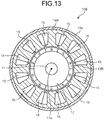
- FIG. 13 is a diagram illustrating a configuration example of an electric motor 10B in the third embodiment.
- the electric motor 10B in the third embodiment includes a magnet 13B instead of the magnet 13A included in the electric motor 10A in the second embodiment.
- the electric motor 10B has the same configuration as that of the electric motor 10A except for the difference between the magnet 13A and the magnet 13B.
- the magnet 13A and the magnet 13B have the same configuration except for the number of poles of the magnet.
- the number of poles of the magnet 13B in the third embodiment is 10. In other words, five N poles and five S poles are alternatively disposed circularly at intervals of 60 degrees about the rotation axis center 11a.
- the larger natural number of the two natural numbers is 5.
- the configurations of an assist mechanism and an electric power steering device in the third embodiment are the same as in the first embodiment except for the points described above.
- the smallest rotation order among rotation orders of the electric motor 10B, the rotation order of the worm 94a, and the rotation order of the coupling 16 are prime to one another.
- the electric motor 10B causes 5th order variation, 10th order variation, and 60th order variation in response to one rotation of the output shaft 11.
- the worm gear causes 2nd order variation and 4th order variation in response to one rotation of the output shaft 11.
- the coupling 16 causes 7th order variation in response to one rotation of the output shaft of the output shaft 11.
- load variations in the electric motor 10B, the worm gear, and the coupling 16 extremely hardly overlap.
- load variation, vibration, and noise can be reduced.
- FIG. 14 is a perspective view of a coupling 216 in the fourth embodiment.
- FIG. 15 is an exploded perspective view of the coupling 216 in the fourth embodiment.
- the coupling 216 is employed instead of the coupling 16 in the first embodiment.
- the coupling 216 includes a first transmission member 217, a second transmission member 218, and a third transmission member 219 that couples the first transmission member 217 and the second transmission member 218.
- the first transmission member 217 has four projections 224 extending toward the third transmission member 219.
- the projection 224 is a fan-shaped projection whose outer side is along the outer circumference of the first transmission member 217 and whose inner side is obtuse.
- the first transmission member 217 is fixed to the output shaft 11 in a manner similar to the first transmission member 17.
- the second transmission member 218 has four projections 228 extending toward the third transmission member 219. Specifically, two pairs of two projections 228 are disposed at positions opposed to each other across the center axis of the rotation shaft portion 94b fixed to the second transmission member 218.
- the two pairs of the projections 228 have a positional relation in which straight lines connecting the second transmission members 218 in the pairs are orthogonal to each other.
- the third transmission member 219 is a plate-shaped member in which L-shaped side portions 236a and 236b continuous so as to draw an obtuse angle and a peripheral portion 237 that connects the side portion 236a of one of the two L shapes and the side portion 236b of the other L shape are continuous so as to form holes corresponding to the shapes of outer peripheral-side cutout portions corresponding to obtuse angles of the first transmission member 217 and the shapes of the projections 228.
- the side portion 236a, the side portion 236b, and the peripheral portion 237 sequentially arranged continuous to form a ring.
- the cutout portion in the form of the L shape drawn by the continuous side portions 236a and 236b is directed to the outer side of the third transmission member 219.
- the cutout portion in the form of the L shape is engaged with the projection 224.
- a hole 255 on the inner peripheral side that is sandwiched between the side portion 236a of one of two L shapes continuous across the peripheral portion 237 and the side portion 236b of the other L shape is engaged with the projection 228.
- the rotation order of the coupling 216 in the fourth embodiment is 4.
- an elastic member 220 is interposed between the first transmission member 217 and the third transmission member 219.
- An elastic member 221 is interposed between the second transmission member 218 and the third transmission member 219.
- the elastic members 220 and 221 are plate-shaped members in which L-shaped side portions 238a and 238b continuous so as to draw an obtuse angle and a peripheral portion 239 that connects the side portion 238a of one of the two L shapes and the side portion 238b of the other L shape are continuous.
- the elastic members 220 and 221 further include claws 242 and cutout portions 243. The claws 242 extend from two opposed peripheral portions 239 of the four peripheral portions 239 toward the third transmission member 219.
- the cutout portions 243 are provided in two peripheral portions 239 from which the claws 242 do not extend.
- a hooking structure of the claw 242 is fitted to a cutout structure of the cutout portion 243.
- the positions of the claw 242 and the cutout portion 243 in the elastic member 220 are out of phase with the positions of the claw 242 and the cutout portion 243 in the elastic member 221 by 90°.
- the claws 242 of one of the elastic member 220 and the elastic member 221 are fitted to the cutout portions 243 of the other elastic member, and the claws 242 of the other elastic member are fitted to the cutout portions 243 of the one elastic member. Consequently, the elastic member 220 and the elastic member 221 are fixed to each other with the third transmission member 219 therebetween.
- the third transmission member 219 has a disc-shaped support portion 241 at a center part of the plate surface. In this manner, the side portions 236a and 236b can be supported from the inner peripheral side, and this further enhances the rigidity.
- the materials and the forming methods of the first transmission member 217, the second transmission member 218, the third transmission member 219, and the elastic members 220 and 221 may be the same as those of the first transmission member 17, the second transmission member 18, the third transmission member 19, and the elastic members 20 and 21, respectively.
- the electric motor 10B in the third embodiment is employed (see FIG. 13 ).
- the larger natural number of the two natural numbers is 5.
- the worm gear shaft 94 has the worm 94c (see FIG. 11 ).
- the rotation order of the worm 94c is 3.
- the smallest rotation order among rotation orders of the electric motor 10B, the rotation order of the worm 94c, and the rotation order of the coupling 216 are prime to one another.
- the configurations of an assist mechanism and an electric power steering device in the fourth embodiment are the same as in the first embodiment except for the points described above.
- the electric motor 10B causes 5th order variation, 10th order variation, and 60th order variation in response to one rotation of the output shaft 11.
- the worm gear causes 3rd order variation and 6th order variation in response to one rotation of the output shaft 11.
- the coupling 216 causes 4th order variation in response to one rotation of the output shaft of the output shaft 11.
- load variations in the electric motor 10B, the worm gear, and the coupling 16 extremely hardly overlap.
- load variation, vibration, and noise can be reduced.
- FIG. 16 is a diagram illustrating a configuration example of an electric motor 10C in the fifth embodiment.
- the electric motor 10C in the fifth embodiment includes a magnet 13C instead of the magnet 13A included in the electric motor 10A in the second embodiment.
- the electric motor 10C has the same configuration as that of the electric motor 10A except for the difference between the magnet 13A and the magnet 13C.
- the magnet 13A and the magnet 13C have the same configuration except for the number of poles of the magnet.
- the number of poles of the magnet 13B in the fifth embodiment is 4.
- two N poles and two S poles are alternatingly disposed circularly at intervals of 60 degrees about the rotation axis center 11a.
- the larger natural number of the two natural numbers is 2.
- the rotation order of the worm and the rotation order of the coupling that are prime to the smallest rotation order among rotation orders of the electric motor 10C are employed.
- the worm gear shaft 94 has the worm 94c (see FIG. 11 ).
- the same coupling 16 as in the first embodiment or the same coupling 116 as in the modification is employed.
- the configurations of an assist mechanism and an electric power steering device in the fifth embodiment are the same as in the first embodiment or the modification except for the points described above.
- load variations in the electric motor 10C, the worm gear, and the coupling 16 or the coupling 116 extremely hardly overlap.
- load variation, vibration, and noise can be reduced.
- FIG. 17 is a diagram illustrating a configuration example of an electric motor 10D in the sixth embodiment.
- the electric motor 10D in the sixth embodiment includes a stator 14B instead of the stator 14A included in the electric motor 10B (see FIG. 13 ) in the third embodiment.
- the electric motor 10D has the same configuration as that of the electric motor 10B except for the difference between the stator 14A and the stator 14B.
- the stator 14A and the stator 14B have the same configuration except for the number of windings 15 and the number of grooves provided with the windings 15.
- the number of poles of magnets 13B in the sixth embodiment is 10.
- the number of windings 15 in the sixth embodiment is 8.
- the electric motor 10D in the sixth embodiment is what is called a "10-pole 8-slot" motor.
- the larger natural number of the two natural numbers is 5.
- the rotation order of the worm and the rotation order of the coupling that are prime to the smallest rotation order among rotation orders of the electric motor 10D are employed.
- the same worm 94a and the same coupling 16 as in the first embodiment are employed.
- the worm 94c (see FIG. 11 ) may be employed instead of the worm 94a.
- the configurations of an assist mechanism and an electric power steering device in the sixth embodiment are the same as in the first embodiment except for the points described above. In this manner, also in the sixth embodiment, load variations in the electric motor 10D, the worm gear, and the coupling 16 extremely hardly overlap. Thus, according to the sixth embodiment, load variation, vibration, and noise can be reduced.
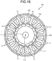
- FIG. 18 is a diagram illustrating a configuration example of an electric motor 10E in the seventh embodiment.
- the electric motor 10E in the seventh embodiment includes a stator 14C instead of the stator 14A included in the electric motor 10A (see FIG. 12 ) in the second embodiment.
- the electric motor 10E has the same configuration as that of the electric motor 10A except for the difference between the stator 14A and the stator 14C.
- the stator 14A and the stator 14C have the same configuration except for the number of poles of a magnet.
- the number of poles of a magnet 13A in the seventh embodiment is 8.
- the number of windings 15 in the seventh embodiment is 16.
- the electric motor 10E in the seventh embodiment is what is called a "8-pole 16-slot" motor.
- the larger natural number of the two natural numbers is 4.
- the rotation order of the worm and the rotation order of the coupling that are prime to the smallest rotation order among rotation orders of the electric motor 10E are employed.
- the worm gear shaft 94 has the worm 94c (see FIG. 11 ).
- the same coupling 16 as in the first embodiment or the same coupling 116 as in the modification is employed.
- the configurations of an assist mechanism and an electric power steering device in the seventh embodiment are the same as in the first embodiment or the modification except for the points described above.
- load variations in the electric motor 10E, the worm gear, and the coupling 16 or the coupling 116 extremely hardly overlap.
- load variation, vibration, and noise can be reduced.
- FIG. 19 is a diagram illustrating a configuration example of an electric motor 10F in the eighth embodiment.
- the electric motor 10F in the eighth embodiment includes the magnet 13 (see FIG. 7 ) included in the electric motor 10A in the first embodiment and the stator 14A (see FIG. 12 ) included in the electric motor 10A in the second embodiment.
- the electric motor 10F has the same configuration as that of the electric motor 10 except for the difference between the stator 14 and the stator 14A.
- the electric motor 10F in the eighth embodiment is what is called a "6-pole 12-slot" motor.
- the larger natural number of the two natural numbers is 3.
- the rotation order of the worm and the rotation order of the coupling that are prime to the smallest rotation order among rotation orders of the electric motor 10F are employed.
- the same worm 94a and the same coupling 16 as in the first embodiment are employed.
- the configurations of an assist mechanism and an electric power steering device in the eighth embodiment are the same as in the first embodiment except for the points described above. In this manner, also in the eighth embodiment, load variations in the electric motor 10F, the worm gear, and the coupling 16 extremely hardly overlap. Consequently, according to the eighth embodiment, load variation, vibration, and noise can be reduced.
- the modification may be applied as in the case of the first embodiment.
- the coupling 116 may be employed instead of the coupling 16.
- load variation, vibration, and noise can be reduced.
- the combination of the smallest rotation order among rotation orders of the electric motor, the rotation order of the worm, and the rotation order of the coupling is not limited to the ones exemplified in the above-mentioned embodiments and modifications. At least two rotation orders of the smallest rotation order among rotation orders of the electric motor, the rotation order of the worm, and the rotation order of the coupling only need to be prime to each other.
- the specific forms of the coupling are not limited to the couplings 16, 116, and 216, and can be changed as appropriate within the range not departing from the matters specifying the present invention.
- the electric motor may be what is called an "outer rotor", in which a rotor is located on the outer peripheral side of a stator.
- the specific forms of the other configurations can also be changed as appropriate within the range not departing from the matters specifying the present invention.
- the above-mentioned electric motor is a brushless motor, but may be a brushed motor.
- the rotor When the electric motor is a brushed motor, the rotor has a winding and the stator has a magnet. A commutator corresponding to the number of poles of the winding is provided to the rotor, and a brush to be brought into sliding contact with the commutator to supply current is provided.
- the rotation order of the electric motor is n times a larger natural number of two natural numbers other than 1 when a multiplication of the two natural numbers expresses the number of poles of the commutator in the rotor.
- the smallest rotation order among rotation orders of a brushed motor in which the number of commutators is 6 (2 ⁇ 3) is 3.
- the smallest rotation order among rotation orders of a brushed motor in which the number of commutators is 8 (2 ⁇ 4) is 4.
- the smallest rotation order among rotation orders of a brushed motor in which the number of commutators is 10 (2 ⁇ 5) is 5.
- At least two rotation orders of the smallest rotation order among rotation orders of the electric motor, the rotation order of the worm, and the rotation order of the coupling are prime to each other, but the rotation orders are not limited to being “prime to each other", and may be "different from each other".
- at least two rotation orders of the smallest rotation order among rotation orders of the electric motor, the rotation order of the worm, and the rotation order of the coupling only need to be different from each other. Consequently, vibration and noise can be reduced as compared with the case where all rotation orders of the smallest rotation order among rotation orders of the electric motor, the rotation order of the worm, and the rotation order of the coupling are equal to one another.
Landscapes
- Engineering & Computer Science (AREA)
- General Engineering & Computer Science (AREA)
- Mechanical Engineering (AREA)
- Power Engineering (AREA)
- Chemical & Material Sciences (AREA)
- Combustion & Propulsion (AREA)
- Transportation (AREA)
- Power Steering Mechanism (AREA)
- Gear Transmission (AREA)
- Connection Of Motors, Electrical Generators, Mechanical Devices, And The Like (AREA)
- Permanent Magnet Type Synchronous Machine (AREA)
Applications Claiming Priority (3)
| Application Number | Priority Date | Filing Date | Title |
|---|---|---|---|
| JP2017254056 | 2017-12-28 | ||
| JP2018170011 | 2018-09-11 | ||
| PCT/JP2018/046512 WO2019131315A1 (ja) | 2017-12-28 | 2018-12-18 | アシスト機構及び電動パワーステアリング装置 |
Publications (3)
| Publication Number | Publication Date |
|---|---|
| EP3733479A1 true EP3733479A1 (de) | 2020-11-04 |
| EP3733479A4 EP3733479A4 (de) | 2021-09-29 |
| EP3733479B1 EP3733479B1 (de) | 2025-08-27 |
Family
ID=67067207
Family Applications (1)
| Application Number | Title | Priority Date | Filing Date |
|---|---|---|---|
| EP18893546.4A Active EP3733479B1 (de) | 2017-12-28 | 2018-12-18 | Hilfsmechanismus und elektrische servolenkung |
Country Status (5)
| Country | Link |
|---|---|
| US (1) | US11702127B2 (de) |
| EP (1) | EP3733479B1 (de) |
| JP (2) | JPWO2019131315A1 (de) |
| CN (1) | CN111542466B (de) |
| WO (1) | WO2019131315A1 (de) |
Cited By (1)
| Publication number | Priority date | Publication date | Assignee | Title |
|---|---|---|---|---|
| EP3851362A4 (de) * | 2018-09-11 | 2022-06-22 | NSK Ltd. | Hilfsmechanismus und elektrische servolenkung |
Families Citing this family (5)
| Publication number | Priority date | Publication date | Assignee | Title |
|---|---|---|---|---|
| CN109790873B (zh) * | 2016-10-13 | 2021-08-31 | 日本精工株式会社 | 力矩传递用接头和电动式助力转向装置 |
| JP7079689B2 (ja) * | 2018-08-07 | 2022-06-02 | 日立Astemo株式会社 | ステアリング装置 |
| JP2022540017A (ja) * | 2019-06-25 | 2022-09-14 | マルチマティック インコーポレーテッド | パワードライブユニットと直流モータのコギング効果を用いた車両ドアチェッカー |
| DE102020104212A1 (de) * | 2020-02-18 | 2021-08-19 | Brose Fahrzeugteile Se & Co. Kommanditgesellschaft, Bamberg | Antriebsanordnung zur motorischen Verstellung eines Verstellelements eines Kraftfahrzeugs |
| DE102020104204A1 (de) * | 2020-02-18 | 2021-08-19 | Brose Fahrzeugteile Se & Co. Kommanditgesellschaft, Bamberg | Antriebsanordnung zur motorischen Verstellung eines Verstellelements eines Kraftfahrzeugs |
Family Cites Families (18)
| Publication number | Priority date | Publication date | Assignee | Title |
|---|---|---|---|---|
| JP2005067371A (ja) | 2003-08-22 | 2005-03-17 | Koyo Seiko Co Ltd | 電動パワーステアリング装置 |
| JP4422567B2 (ja) * | 2004-06-30 | 2010-02-24 | 株式会社日立製作所 | モータ駆動装置,電動アクチュエータおよび電動パワーステアリング装置 |
| JP2006046376A (ja) | 2004-07-30 | 2006-02-16 | Koyo Seiko Co Ltd | 減速機および電動パワーステアリング装置 |
| JP4478537B2 (ja) * | 2004-09-03 | 2010-06-09 | 日本ビクター株式会社 | ブラシレスモータ |
| JP4294657B2 (ja) | 2006-06-20 | 2009-07-15 | アスモ株式会社 | カップリング装置、モータ装置、及びワイパモータ |
| JP2009148146A (ja) * | 2007-11-22 | 2009-07-02 | Seiko Epson Corp | 電動装置 |
| JP4459278B2 (ja) * | 2008-03-27 | 2010-04-28 | 本田技研工業株式会社 | 伸縮アクチュエータ |
| JP2011255818A (ja) * | 2010-06-10 | 2011-12-22 | Jtekt Corp | 電動パワーステアリング装置 |
| JP5675721B2 (ja) * | 2012-07-18 | 2015-02-25 | 株式会社ミツバ | 電動式ベッド用リニアアクチュエータ |
| JP5960281B2 (ja) * | 2012-11-19 | 2016-08-02 | 本田技研工業株式会社 | 電動パワーステアリング装置 |
| JP6252131B2 (ja) * | 2013-11-22 | 2017-12-27 | 株式会社ジェイテクト | 電動モータ及び電動パワーステアリング装置 |
| JP2016082685A (ja) * | 2014-10-15 | 2016-05-16 | 本田技研工業株式会社 | ブラシレスモータ及び電動パワーステアリング装置 |
| US9755470B2 (en) * | 2014-10-30 | 2017-09-05 | Mitsubishi Electric Corporation | Rotary electric machine and electric power steering device using rotary electric machine |
| CN107534331B (zh) * | 2015-04-22 | 2019-08-13 | 三菱电机株式会社 | 旋转电机以及电动动力转向装置 |
| JP6653874B2 (ja) | 2015-08-04 | 2020-02-26 | オイレス工業株式会社 | 電動式パワーステアリング装置用の軸連結機構 |
| US20200290666A1 (en) | 2016-03-08 | 2020-09-17 | Nsk Ltd. | Joint for torque transmission and electric power steering device |
| EP3540937A4 (de) * | 2016-11-10 | 2020-06-03 | NSK Ltd. | Elektrische servolenkvorrichtung |
| JP7024879B2 (ja) | 2018-09-11 | 2022-02-24 | 日本精工株式会社 | アシスト機構及び電動パワーステアリング装置 |
-
2018
- 2018-12-18 US US16/957,961 patent/US11702127B2/en active Active
- 2018-12-18 CN CN201880084080.XA patent/CN111542466B/zh active Active
- 2018-12-18 WO PCT/JP2018/046512 patent/WO2019131315A1/ja not_active Ceased
- 2018-12-18 EP EP18893546.4A patent/EP3733479B1/de active Active
- 2018-12-18 JP JP2019561539A patent/JPWO2019131315A1/ja active Pending
-
2022
- 2022-06-30 JP JP2022105495A patent/JP7355169B2/ja active Active
Cited By (2)
| Publication number | Priority date | Publication date | Assignee | Title |
|---|---|---|---|---|
| EP3851362A4 (de) * | 2018-09-11 | 2022-06-22 | NSK Ltd. | Hilfsmechanismus und elektrische servolenkung |
| US11814116B2 (en) | 2018-09-11 | 2023-11-14 | Nsk Ltd. | Assist mechanism and electric power steering device |
Also Published As
| Publication number | Publication date |
|---|---|
| US11702127B2 (en) | 2023-07-18 |
| EP3733479A4 (de) | 2021-09-29 |
| JPWO2019131315A1 (ja) | 2021-01-07 |
| US20200369315A1 (en) | 2020-11-26 |
| CN111542466B (zh) | 2023-04-04 |
| CN111542466A (zh) | 2020-08-14 |
| JP2022128492A (ja) | 2022-09-01 |
| JP7355169B2 (ja) | 2023-10-03 |
| EP3733479B1 (de) | 2025-08-27 |
| WO2019131315A1 (ja) | 2019-07-04 |
Similar Documents
| Publication | Publication Date | Title |
|---|---|---|
| EP3733479B1 (de) | Hilfsmechanismus und elektrische servolenkung | |
| EP3121954B1 (de) | Elektromotorsteuerungsvorrichtung, elektrische servolenkvorrichtung und fahrzeug | |
| CN105993113B (zh) | 电动机、电动动力转向装置和车辆 | |
| US8434585B2 (en) | Electric power steering system and vehicle steering system | |
| US11814116B2 (en) | Assist mechanism and electric power steering device | |
| US10414428B2 (en) | Drive device and electric power steering apparatus | |
| KR20100014886A (ko) | 중첩식 가변 필드 다이나모일렉트릭 장치 | |
| EP2589935A2 (de) | Drehwinkelerfassungsvorrichtung und Drehmomentsensor | |
| CN109428407B (zh) | 定子芯 | |
| JP2008301601A (ja) | ブラシレスモータ | |
| JP5962027B2 (ja) | 回転電機 | |
| JP2013223281A (ja) | 電動モータ | |
| US7893580B2 (en) | Positioning mechanism of resolver and electrically-driven power steering apparatus | |
| WO2015193715A1 (en) | Switched reluctance motor | |
| JP2006027340A (ja) | 電動パワーステアリング装置 | |
| JP5973141B2 (ja) | ブラシレスモータと、これを利用する電動パワーステアリング装置 | |
| EP4516567A1 (de) | Fahrzeugantriebsvorrichtung | |
| JP2016010270A (ja) | 回転電機及び回転電機の制御装置 | |
| JP2009101494A (ja) | 駆動装置 |
Legal Events
| Date | Code | Title | Description |
|---|---|---|---|
| STAA | Information on the status of an ep patent application or granted ep patent |
Free format text: STATUS: THE INTERNATIONAL PUBLICATION HAS BEEN MADE |
|
| PUAI | Public reference made under article 153(3) epc to a published international application that has entered the european phase |
Free format text: ORIGINAL CODE: 0009012 |
|
| STAA | Information on the status of an ep patent application or granted ep patent |
Free format text: STATUS: REQUEST FOR EXAMINATION WAS MADE |
|
| 17P | Request for examination filed |
Effective date: 20200624 |
|
| AK | Designated contracting states |
Kind code of ref document: A1 Designated state(s): AL AT BE BG CH CY CZ DE DK EE ES FI FR GB GR HR HU IE IS IT LI LT LU LV MC MK MT NL NO PL PT RO RS SE SI SK SM TR |
|
| AX | Request for extension of the european patent |
Extension state: BA ME |
|
| DAV | Request for validation of the european patent (deleted) | ||
| DAX | Request for extension of the european patent (deleted) | ||
| A4 | Supplementary search report drawn up and despatched |
Effective date: 20210827 |
|
| RIC1 | Information provided on ipc code assigned before grant |
Ipc: F16D 27/10 20060101ALI20210823BHEP Ipc: H02K 21/14 20060101ALI20210823BHEP Ipc: H02K 7/116 20060101ALI20210823BHEP Ipc: F16H 1/16 20060101ALI20210823BHEP Ipc: F16D 3/74 20060101ALI20210823BHEP Ipc: F16D 3/68 20060101ALI20210823BHEP Ipc: F16D 3/50 20060101ALI20210823BHEP Ipc: B62D 5/04 20060101AFI20210823BHEP |
|
| STAA | Information on the status of an ep patent application or granted ep patent |
Free format text: STATUS: EXAMINATION IS IN PROGRESS |
|
| 17Q | First examination report despatched |
Effective date: 20220826 |
|
| GRAP | Despatch of communication of intention to grant a patent |
Free format text: ORIGINAL CODE: EPIDOSNIGR1 |
|
| STAA | Information on the status of an ep patent application or granted ep patent |
Free format text: STATUS: GRANT OF PATENT IS INTENDED |
|
| INTG | Intention to grant announced |
Effective date: 20250410 |
|
| GRAS | Grant fee paid |
Free format text: ORIGINAL CODE: EPIDOSNIGR3 |
|
| GRAA | (expected) grant |
Free format text: ORIGINAL CODE: 0009210 |
|
| STAA | Information on the status of an ep patent application or granted ep patent |
Free format text: STATUS: THE PATENT HAS BEEN GRANTED |
|
| AK | Designated contracting states |
Kind code of ref document: B1 Designated state(s): AL AT BE BG CH CY CZ DE DK EE ES FI FR GB GR HR HU IE IS IT LI LT LU LV MC MK MT NL NO PL PT RO RS SE SI SK SM TR |
|
| REG | Reference to a national code |
Ref country code: GB Ref legal event code: FG4D |
|
| REG | Reference to a national code |
Ref country code: CH Ref legal event code: EP |
|
| REG | Reference to a national code |
Ref country code: DE Ref legal event code: R096 Ref document number: 602018085073 Country of ref document: DE |
|
| REG | Reference to a national code |
Ref country code: IE Ref legal event code: FG4D |
|
| REG | Reference to a national code |
Ref country code: NL Ref legal event code: MP Effective date: 20250827 |
|
| PG25 | Lapsed in a contracting state [announced via postgrant information from national office to epo] |
Ref country code: IS Free format text: LAPSE BECAUSE OF FAILURE TO SUBMIT A TRANSLATION OF THE DESCRIPTION OR TO PAY THE FEE WITHIN THE PRESCRIBED TIME-LIMIT Effective date: 20251227 |
|
| PGFP | Annual fee paid to national office [announced via postgrant information from national office to epo] |
Ref country code: DE Payment date: 20251028 Year of fee payment: 8 |
|
| PG25 | Lapsed in a contracting state [announced via postgrant information from national office to epo] |
Ref country code: NO Free format text: LAPSE BECAUSE OF FAILURE TO SUBMIT A TRANSLATION OF THE DESCRIPTION OR TO PAY THE FEE WITHIN THE PRESCRIBED TIME-LIMIT Effective date: 20251127 |
|
| REG | Reference to a national code |
Ref country code: LT Ref legal event code: MG9D |
|
| PG25 | Lapsed in a contracting state [announced via postgrant information from national office to epo] |
Ref country code: PT Free format text: LAPSE BECAUSE OF FAILURE TO SUBMIT A TRANSLATION OF THE DESCRIPTION OR TO PAY THE FEE WITHIN THE PRESCRIBED TIME-LIMIT Effective date: 20251229 |
|
| PG25 | Lapsed in a contracting state [announced via postgrant information from national office to epo] |
Ref country code: FI Free format text: LAPSE BECAUSE OF FAILURE TO SUBMIT A TRANSLATION OF THE DESCRIPTION OR TO PAY THE FEE WITHIN THE PRESCRIBED TIME-LIMIT Effective date: 20250827 |
|
| PG25 | Lapsed in a contracting state [announced via postgrant information from national office to epo] |
Ref country code: NL Free format text: LAPSE BECAUSE OF FAILURE TO SUBMIT A TRANSLATION OF THE DESCRIPTION OR TO PAY THE FEE WITHIN THE PRESCRIBED TIME-LIMIT Effective date: 20250827 Ref country code: HR Free format text: LAPSE BECAUSE OF FAILURE TO SUBMIT A TRANSLATION OF THE DESCRIPTION OR TO PAY THE FEE WITHIN THE PRESCRIBED TIME-LIMIT Effective date: 20250827 |
|
| PGFP | Annual fee paid to national office [announced via postgrant information from national office to epo] |
Ref country code: FR Payment date: 20251110 Year of fee payment: 8 |
|
| PG25 | Lapsed in a contracting state [announced via postgrant information from national office to epo] |
Ref country code: GR Free format text: LAPSE BECAUSE OF FAILURE TO SUBMIT A TRANSLATION OF THE DESCRIPTION OR TO PAY THE FEE WITHIN THE PRESCRIBED TIME-LIMIT Effective date: 20251128 |
|
| PG25 | Lapsed in a contracting state [announced via postgrant information from national office to epo] |
Ref country code: SE Free format text: LAPSE BECAUSE OF FAILURE TO SUBMIT A TRANSLATION OF THE DESCRIPTION OR TO PAY THE FEE WITHIN THE PRESCRIBED TIME-LIMIT Effective date: 20250827 |
|
| PG25 | Lapsed in a contracting state [announced via postgrant information from national office to epo] |
Ref country code: LV Free format text: LAPSE BECAUSE OF FAILURE TO SUBMIT A TRANSLATION OF THE DESCRIPTION OR TO PAY THE FEE WITHIN THE PRESCRIBED TIME-LIMIT Effective date: 20250827 |
|
| PG25 | Lapsed in a contracting state [announced via postgrant information from national office to epo] |
Ref country code: BG Free format text: LAPSE BECAUSE OF FAILURE TO SUBMIT A TRANSLATION OF THE DESCRIPTION OR TO PAY THE FEE WITHIN THE PRESCRIBED TIME-LIMIT Effective date: 20250827 Ref country code: PL Free format text: LAPSE BECAUSE OF FAILURE TO SUBMIT A TRANSLATION OF THE DESCRIPTION OR TO PAY THE FEE WITHIN THE PRESCRIBED TIME-LIMIT Effective date: 20250827 |
|
| PG25 | Lapsed in a contracting state [announced via postgrant information from national office to epo] |
Ref country code: RS Free format text: LAPSE BECAUSE OF FAILURE TO SUBMIT A TRANSLATION OF THE DESCRIPTION OR TO PAY THE FEE WITHIN THE PRESCRIBED TIME-LIMIT Effective date: 20251127 |
|
| PG25 | Lapsed in a contracting state [announced via postgrant information from national office to epo] |
Ref country code: ES Free format text: LAPSE BECAUSE OF FAILURE TO SUBMIT A TRANSLATION OF THE DESCRIPTION OR TO PAY THE FEE WITHIN THE PRESCRIBED TIME-LIMIT Effective date: 20250827 |
|
| REG | Reference to a national code |
Ref country code: AT Ref legal event code: MK05 Ref document number: 1829705 Country of ref document: AT Kind code of ref document: T Effective date: 20250827 |
|
| PG25 | Lapsed in a contracting state [announced via postgrant information from national office to epo] |
Ref country code: RO Free format text: LAPSE BECAUSE OF FAILURE TO SUBMIT A TRANSLATION OF THE DESCRIPTION OR TO PAY THE FEE WITHIN THE PRESCRIBED TIME-LIMIT Effective date: 20250827 |
|
| PG25 | Lapsed in a contracting state [announced via postgrant information from national office to epo] |
Ref country code: SM Free format text: LAPSE BECAUSE OF FAILURE TO SUBMIT A TRANSLATION OF THE DESCRIPTION OR TO PAY THE FEE WITHIN THE PRESCRIBED TIME-LIMIT Effective date: 20250827 |
|
| PG25 | Lapsed in a contracting state [announced via postgrant information from national office to epo] |
Ref country code: DK Free format text: LAPSE BECAUSE OF FAILURE TO SUBMIT A TRANSLATION OF THE DESCRIPTION OR TO PAY THE FEE WITHIN THE PRESCRIBED TIME-LIMIT Effective date: 20250827 |
|
| PG25 | Lapsed in a contracting state [announced via postgrant information from national office to epo] |
Ref country code: AT Free format text: LAPSE BECAUSE OF FAILURE TO SUBMIT A TRANSLATION OF THE DESCRIPTION OR TO PAY THE FEE WITHIN THE PRESCRIBED TIME-LIMIT Effective date: 20250827 |
|
| PG25 | Lapsed in a contracting state [announced via postgrant information from national office to epo] |
Ref country code: IT Free format text: LAPSE BECAUSE OF FAILURE TO SUBMIT A TRANSLATION OF THE DESCRIPTION OR TO PAY THE FEE WITHIN THE PRESCRIBED TIME-LIMIT Effective date: 20250827 |
|
| PG25 | Lapsed in a contracting state [announced via postgrant information from national office to epo] |
Ref country code: CZ Free format text: LAPSE BECAUSE OF FAILURE TO SUBMIT A TRANSLATION OF THE DESCRIPTION OR TO PAY THE FEE WITHIN THE PRESCRIBED TIME-LIMIT Effective date: 20250827 |
|
| PG25 | Lapsed in a contracting state [announced via postgrant information from national office to epo] |
Ref country code: EE Free format text: LAPSE BECAUSE OF FAILURE TO SUBMIT A TRANSLATION OF THE DESCRIPTION OR TO PAY THE FEE WITHIN THE PRESCRIBED TIME-LIMIT Effective date: 20250827 Ref country code: SK Free format text: LAPSE BECAUSE OF FAILURE TO SUBMIT A TRANSLATION OF THE DESCRIPTION OR TO PAY THE FEE WITHIN THE PRESCRIBED TIME-LIMIT Effective date: 20250827 |